JP2007506601A - Air conditioner for vehicles - Google Patents
Air conditioner for vehicles Download PDFInfo
- Publication number
- JP2007506601A JP2007506601A JP2006516003A JP2006516003A JP2007506601A JP 2007506601 A JP2007506601 A JP 2007506601A JP 2006516003 A JP2006516003 A JP 2006516003A JP 2006516003 A JP2006516003 A JP 2006516003A JP 2007506601 A JP2007506601 A JP 2007506601A
- Authority
- JP
- Japan
- Prior art keywords
- air
- flap
- passage
- flow
- mixing
- Prior art date
- Legal status (The legal status is an assumption and is not a legal conclusion. Google has not performed a legal analysis and makes no representation as to the accuracy of the status listed.)
- Pending
Links
Images


Classifications
-
- B—PERFORMING OPERATIONS; TRANSPORTING
- B60—VEHICLES IN GENERAL
- B60H—ARRANGEMENTS OF HEATING, COOLING, VENTILATING OR OTHER AIR-TREATING DEVICES SPECIALLY ADAPTED FOR PASSENGER OR GOODS SPACES OF VEHICLES
- B60H1/00—Heating, cooling or ventilating [HVAC] devices
- B60H1/00642—Control systems or circuits; Control members or indication devices for heating, cooling or ventilating devices
- B60H1/00664—Construction or arrangement of damper doors
- B60H1/00671—Damper doors moved by rotation; Grilles
- B60H1/00685—Damper doors moved by rotation; Grilles the door being a rotating disc or cylinder or part thereof
-
- B—PERFORMING OPERATIONS; TRANSPORTING
- B60—VEHICLES IN GENERAL
- B60H—ARRANGEMENTS OF HEATING, COOLING, VENTILATING OR OTHER AIR-TREATING DEVICES SPECIALLY ADAPTED FOR PASSENGER OR GOODS SPACES OF VEHICLES
- B60H1/00—Heating, cooling or ventilating [HVAC] devices
- B60H1/00642—Control systems or circuits; Control members or indication devices for heating, cooling or ventilating devices
- B60H1/00664—Construction or arrangement of damper doors
- B60H2001/00721—Air deflecting or air directing means
Abstract
Description
本発明は、車両用空調装置に関する。 The present invention relates to a vehicle air conditioner.
車両用空調装置は、典型的には、一体的または複数に分かれたハウジング、新気または周囲空気を吸い込むための送風機、熱交換機、特に空気を冷却するための蒸発器、空気を加熱するための第2の熱交換機、メイン空気流を温度調節するための装置および混合室から構成される。 A vehicle air conditioner typically has an integral or divided housing, a blower for drawing fresh air or ambient air, a heat exchanger, in particular an evaporator for cooling the air, for heating the air. It consists of a second heat exchanger, a device for adjusting the temperature of the main air flow and a mixing chamber.
蒸発器から流出する冷却された空気流は、好ましくは第1の部分空気流として直接通路または冷風通路を介して混合室内へ案内されて、第1の部分空気流として他の通路を介して、蒸発器の下流に位置する、発熱体として形成された、他の熱交換機へ供給される。発熱体を介して案内される第2の部分空気流は、加熱された空気流として混合室へ流入し、、第1の冷たい部分空気流の少なくとも一部と混合された後に、メイン空気流を形成する。 The cooled air stream exiting the evaporator is preferably guided as a first partial air stream into the mixing chamber via a direct passage or a cold air passage and as a first partial air stream through the other passages, It is supplied to another heat exchanger formed as a heating element located downstream of the evaporator. The second partial air flow guided through the heating element flows into the mixing chamber as a heated air flow and is mixed with at least a portion of the first cold partial air flow before the main air flow. Form.
混合室または混合チャンバから出て、メイン空気流は種々の空気流出開口部を介して車両室内を潤す。これらの空気流出開口部あるいは、たとえばデフロスト空気流出部、混合空気流出部あるいは足下空間空気流出部のような流出部は、他の制御フラップを介して空気量的に様々に供給可能である。 Out of the mixing chamber or mixing chamber, the main air flow moistens the vehicle interior through various air outlet openings. These air outflow openings or outflow portions such as defrost air outflow portions, mixed air outflow portions or foot space air outflow portions can be supplied in various amounts via the other control flaps.
空気を温度調節する装置によって調節可能な、冷たい部分空気流と暖められた部分空気流からなる様々な体積流によって、メイン空気流ないし混合室内の空気の温度が生じる。混合室から車両室内の様々な領域またはゾーンへ案内されるメイン空気流を温度調節する、この種の装置は、大体において、温度混合フラップまたはこの種の温度混合フラップの配置からなる。この種の混合フラップの様々な駆動位置によって、種々の空気流通路の供給を調節し、あるいは制御することが可能である。特に、2つまたはそれより多くの異なるように温度調節された空気流を一緒に案内し、あるいは混合した後に定められた温度を得るために、これら2つまたはそれより多い空気流の混合比を調節することができる。 Various volumetric flows, consisting of a cold partial air stream and a warmed partial air stream, adjustable by means of a device for temperature-controlling the air, produce the temperature of the main air stream or the air in the mixing chamber. This type of device for regulating the temperature of the main air flow guided from the mixing chamber to various areas or zones in the vehicle compartment consists largely of a temperature mixing flap or an arrangement of such a temperature mixing flap. Depending on the various drive positions of this type of mixing flap, it is possible to adjust or control the supply of the various air flow passages. In particular, the mixing ratio of these two or more air streams is used to obtain a defined temperature after guiding or mixing two or more differently temperature-controlled air streams together. Can be adjusted.
従来技術(たとえば、特許文献1)から、この種の温度調節フラップのために、いわゆるバタフライ弁が知られている。これは、2つの羽根で形成されて、回転軸を中心に回転可能または揺動可能に軸承されており、2つの終端位置間で移動することができる。その場合にフラップまたはフラップの部分領域は、一方の終端位置において冷風通路を完全に閉鎖し、同時に、空気流を加熱部材へ案内する、温風通路を開放する。第2の終端位置においては、逆の場合が生じる。フラップは、加熱部材への通路を完全に閉鎖し、混合室内へは冷風通路を介して冷たい空気のみが達する。フラップの、その間にある位置において、冷風通路と温風通路が部分的に閉鎖され、ないしは開放されるので、フラップ位置に従って、2つの空気流が合体する混合室内に所定の温度が生じる。 A so-called butterfly valve is known from the prior art (for example, Patent Document 1) for this type of temperature control flap. This is formed of two blades and is supported so as to be rotatable or swingable about a rotation axis, and can move between two end positions. In that case, the flap or the partial area of the flap completely closes the cold air passage at one end position and at the same time opens the hot air passage which guides the air flow to the heating element. The opposite case occurs at the second end position. The flap completely closes the passage to the heating element, and only cold air reaches the mixing chamber via the cold air passage. Since the cold air passage and the hot air passage are partially closed or opened at a position between the flaps, a predetermined temperature is generated in the mixing chamber where the two air flows are combined according to the flap position.
フラップが、たとえば冷風通路を閉鎖する、一方の終端位置にある場合に、このフラップは、混合空気のわずかな温度低下を得るためには、小さい角度だけ回動される。混合フラップの、冷風通路を閉鎖する羽根部分の終端領域に、混合室内へ冷たい空気を通過させるための狭い開口部が開けられている。その場合の欠点は、バタフライ弁においては構造に基づいてこの開口部領域がフラップの、温風通路とは逆の側に位置する端部に設けられていることである。冷却された空気は、冷風通路の端縁領域に沿ってフラップ端部を撫でながら混合室内へ達し、それによって暖かい空気と冷たい空気のわずかな混合しか得られない。すなわちこの端縁領域に隣接している流出開口部は、圧倒的に冷たい空気を供給され、ずっと離れた開口部はほぼ暖かい空気のみを供給される。このことが、混合室からの空気流出開口部に関して、しばしば望ましくない温度の層をもたらす。同様なことは、まず完全に閉鎖された温風通路が徐々に開放される、逆の場合についても当てはまる。 If the flap is in one end position, for example closing the cold air passage, this flap is rotated by a small angle in order to obtain a slight temperature drop of the mixed air. A narrow opening for passing cold air into the mixing chamber is opened in the end region of the blade portion of the mixing flap that closes the cool air passage. The disadvantage in that case is that, in the butterfly valve, this opening region is provided at the end of the flap located on the side opposite to the hot air passage, based on the structure. The cooled air reaches the mixing chamber while stroking the flap end along the edge region of the cold air passage, thereby providing only a slight mixing of warm and cold air. That is, the outflow opening adjacent to this edge region is overwhelmed with cold air, and the far opening is only supplied with substantially warm air. This often results in an undesired temperature layer for the air outflow opening from the mixing chamber. The same is true for the reverse case, where the completely closed warm air passage is first gradually opened.
部分空気流の改良された混合が、バタフライ弁の混合フラップによって、回転軸ないし回転軸の領域のフラップ壁を端縁領域または冷風通路と温風通路の間の仕切壁の端部から離すことにより得られるので、混合フラップの、終端位置の間にある位置において、冷風通路からの冷風を温風通路内へ直接通過させることができ、すなわち混合室内へ流入する前にすでに、2つの部分空気流の改良された混合がもたらされる。しかし、この配置の欠点は、フラップを2つの羽根で形成することによって、冷風通路と温風通路の開口幅の合計によって定められる、フラップ全体寸法が生じることである。この形態の例が、従来技術(たとえば、特許文献2を参照)に示されている。 Improved mixing of the partial air flow is achieved by separating the flap wall of the rotary shaft or the rotary shaft region from the edge region or the end of the partition wall between the cold air passage and the hot air passage by the mixing flap of the butterfly valve. As a result, at the position of the mixing flap between the end positions, the cold air from the cold air passage can be passed directly into the hot air passage, i.e. before it enters the mixing chamber, Improved mixing. However, a disadvantage of this arrangement is that the flap is formed by two blades, resulting in the overall flap dimensions defined by the sum of the opening widths of the cold air passage and the hot air passage. An example of this form is shown in the prior art (see, for example, Patent Document 2).
考え方においてこの問題に対処する混合フラップを有する空調装置が、従来技術(たとえば、特許文献3)から知られている。温度混合フラップは、ドラムフラップあるいは少なくともドラム状のフラップとして形成されている。ドラム状のフラップの主要な特徴は、それが円形または回転軸に関して凸状に形成された壁を有していることである。通路を閉鎖し、ないしは開放するために設けられている壁領域の全寸法は、2つの通路のうちの広い方の最大の開口幅のみによって定められる。図示の実施形態において、フラップは、回転軸を中心に回転可能に軸承されている。円セグメント状に形成された閉鎖壁には、2つの終端位置「冷」と「温」の間で揺動する間に冷風通路から温風通路への直接的な通過を可能にするために、1つまたは複数の切欠きないし閉鎖壁から引っ込んだ領域が設けられている。 An air conditioner having a mixing flap that addresses this problem in concept is known from the prior art (e.g. Patent Document 3). The temperature mixing flap is formed as a drum flap or at least a drum-shaped flap. The main feature of the drum-shaped flap is that it has a wall that is circular or convex with respect to the axis of rotation. The overall size of the wall area provided for closing or opening the passage is defined only by the widest opening width of the two passages. In the illustrated embodiment, the flap is rotatably supported about the rotation axis. In order to allow a direct passage from the cold air passage to the hot air passage while swinging between the two end positions "cold" and "warm", the closed wall formed in a circular segment shape, One or more notches or regions recessed from the closure wall are provided.
方向変換される冷風の流れ領域におけるフラップの凸状に湾曲された形状によって、流れ特性にマイナスの作用が生じる。定められたフラップ位置において、流入する冷風流の優先方向が、閉鎖壁に対してほぼ垂直になっている。壁に当接する冷風は、まだ温風通路内へオーバーフローする前に旋回する。従って冷風の方向変換をもたらす閉鎖壁が、流れ障害物を形成する。それからもたらされる圧力降下によって、空調装置の音響的特性も悪化する。
従って従来技術に基づいて、本発明の課題は、空気流に、特に空気方向変換の機能に最適に合わせられたプロフィールを備えた温度混合弁を有する、改良された空調装置を提供することである。 Therefore, based on the prior art, the object of the present invention is to provide an improved air conditioner having a temperature mixing valve with a profile that is optimally adapted to the air flow, in particular to the function of the air redirecting. .
この課題は、請求項1の特徴を有する空調装置、
(すなわち、
・空気流を発生させるための送風機と、
・送風機の下流側に配置された、空気流によって貫流される蒸発器と、
・蒸発器の後段に配置された混合フラップと、
を有し、
・空気流が混合フラップによって第1の流れ通路および/または第2の流れ通路へ分割可能であって、それによって第1および/または第2の部分空気流が発生可能であり、
・第1の流れ通路(冷風通路)が混合室内へ連通し、
・第2の流れ通路(温風通路)内には第2の部分空気流を加熱するための熱交換機が配置されており、かつ第2の流れ通路が熱交換機の下流側で混合室内へ連通しており、
・混合室内で第1と第2の部分空気流から混合空気流が形成可能であって、その場合に混合室から空気流出通路が車両室内の様々な領域へ通じており、
・かつ、混合フラップが回転軸を中心に、第1の流れ通路を完全に閉鎖する第1の終端位置と、第2の流れ通路を完全に閉鎖する第2の終端位置の間で揺動可能であって、かつその間にある位置においては、第1の流れ通路から第2の流れ通路への冷風の直接的な通過を可能にする、
車両用空調装置において、
混合フラップが空気流を分割するために、少なくとも3つの部分からなり、かつ回転軸がこれらの部分の外側に位置し、第1の部分は回転軸に関して半径方向に、または少なくとも半径方向に対して鋭角で、第2の部分は回転軸に関して凹状に、そして第3の部分は回転軸に関して半径方向に、あるいは少なくとも半径方向に対して鋭角で配置されて、第1と第3の部分が第2の部分の両側の端部に、3つの部分がつながった輪郭を有する壁領域を形成するように、接続されていることを特徴とする、車両用空調装置)、
によって解決される。好ましい形態が、従属請求項の対象である。
This subject is an air conditioner having the features of
(I.e.
A blower for generating an air flow;
An evaporator arranged on the downstream side of the blower, which flows through by the air flow;
A mixing flap placed after the evaporator;
Have
The air flow can be divided into a first flow path and / or a second flow path by means of a mixing flap, whereby a first and / or a second partial air flow can be generated;
The first flow passage (cold air passage) communicates with the mixing chamber,
A heat exchanger for heating the second partial air flow is disposed in the second flow passage (warm air passage), and the second flow passage communicates with the mixing chamber on the downstream side of the heat exchanger. And
A mixed air flow can be formed from the first and second partial air flows in the mixing chamber, in which case the air outflow passage leads from the mixing chamber to various regions in the vehicle compartment,
-And the mixing flap can swing between a first end position that completely closes the first flow passage and a second end position that completely closes the second flow passage about the rotation axis Allowing direct passage of cold air from the first flow passage to the second flow passage at a position in between,
In vehicle air conditioners,
The mixing flap consists of at least three parts for dividing the air flow and the axis of rotation is located outside these parts, the first part being radially with respect to the axis of rotation or at least with respect to the radial direction At an acute angle, the second part is concave with respect to the axis of rotation and the third part is arranged radially with respect to the axis of rotation, or at least at an acute angle with respect to the radial direction, the first and third parts being the second An air conditioner for vehicles, characterized in that it is connected to end portions on both sides of the part of the part so as to form a wall region having a contour in which the three parts are connected)
Solved by. Preferred forms are the subject of the dependent claims.
本発明によれば、空調装置は、空気流を発生させるために送風機を有している。この送風機の下流側に、蒸発器が配置されている。蒸発器の後方で、空気流は混合フラップによって第1の流れ通路および/または第2の流れ通路へ分割され、それによって第1および/または第2の部分空気流が発生可能である。第1の流れ通路は、混合室内へ連通し、第2の流れ通路内には、第2の部分空気流を加熱するために熱交換機が配置されており、熱交換機の下流側で初めて混合室内へ連通する。 According to the present invention, the air conditioner has a blower to generate an air flow. An evaporator is disposed on the downstream side of the blower. Behind the evaporator, the air flow is divided by the mixing flap into the first flow path and / or the second flow path, whereby a first and / or second partial air flow can be generated. The first flow passage communicates with the mixing chamber, and a heat exchanger is disposed in the second flow passage to heat the second partial air flow. To communicate.
混合室内で、第1と第2の部分空気流から混合空気流またはメイン空気流が発生可能であり、その場合に混合室から空気流出通路が車両室内の様々な領域またはゾーンへ通じている。たとえばデフロスト空気通路、中央空気通路、側方空気通路あるいは足下空間空気通路のような、空気流出通路に、好ましくは付加的な切替えフラップが対応づけられており、それらが混合室から対応づけられた空気流出通路を通る空気流出流を制御する。 In the mixing chamber, a mixed air flow or a main air flow can be generated from the first and second partial air flows, in which case an air outflow passage leads from the mixing chamber to various regions or zones in the vehicle chamber. An additional switching flap is preferably associated with the air outflow passage, such as a defrost air passage, a central air passage, a side air passage or a foot space air passage, which are associated from the mixing chamber. Control the air outflow through the air outflow passage.
空気流を分割するための、本発明に基づく混合フラップは、少なくとも3つの部分からなり、それらが好ましくは一体的に互いに結合されているので、つながり合った、一貫した輪郭が生じる。この輪郭が、フラップの壁領域を形成する。混合フラップは、回転軸を有しており、その回転軸はこの壁領域の外部の、好ましくは混合室の領域にある。フラップの、壁領域を形成する部分から、2つの部分が回転軸に対して半径方向に延びており、あるいはこの半径方向と鋭角を形成する。少なくとも1つの他の部分が、これら2つの部分の間にあって、回転軸に関して凹状に湾曲されている。混合フラップは、その回転軸を中心に2つの終端位置の間で回転可能ないし揺動可能である。第1の終端位置において、混合フラップは第1の流れ通路、たとえば冷風通路を完全に閉鎖し、第2の流れ通路、たとえば温風通路を開放する。第2の終端位置において、混合フラップは第1の流れ通路(冷風通路)を開放し、第2の流れ通路(温風通路)を完全に閉鎖する。これらの終端位置の間にある位置においては、フラップの壁領域の部分が凹状に形成されていることにより、冷風を直接温風通路内へ通過させることが可能である。 The mixing flap according to the invention for dividing the air flow consists of at least three parts, which are preferably joined together so that a connected and consistent contour results. This contour forms the wall area of the flap. The mixing flap has a rotation axis which is outside this wall region, preferably in the region of the mixing chamber. From the part of the flap forming the wall region, two parts extend radially with respect to the axis of rotation or form an acute angle with this radial direction. At least one other part is between these two parts and is concavely curved with respect to the axis of rotation. The mixing flap is rotatable or swingable between two end positions around its rotation axis. In the first terminal position, the mixing flap completely closes the first flow passage, for example the cold air passage, and opens the second flow passage, for example the hot air passage. In the second end position, the mixing flap opens the first flow passage (cold air passage) and completely closes the second flow passage (hot air passage). In the position between these terminal positions, the portion of the wall region of the flap is formed in a concave shape, so that the cool air can be directly passed into the hot air passage.
混合フラップの壁領域は、構造的に、凹状の部分が主要な部分を形成するように、構成されており、その場合にその端部に連続する半径方向または半径方向に対して鋭角に形成された部分が、フラップの端縁領域上に延びている。本発明によれば、壁領域の凹状の屈曲または湾曲によってフラップの、終端位置の間にある位置において、温風通路への冷風の直接的な通過が可能になるだけでなく、温風通路への入口の前で旋回をできる限り回避しながら冷風流の一部のソフトな方向変換が行われる。方向変換される流れは、フラップの極めて凹状の形状によって、温風通路内の混合領域内で暖かい空気流の流れ方向に対して反対の流れ方向が得られ、それによって温風通路が混合室内へ連通する前に、空気流の極めて効果的な混合が行われるように、案内することができる。 The wall area of the mixing flap is structurally configured in such a way that the concave part forms the main part, in which case it is formed at an acute angle with respect to the radial direction or in the radial direction continuous to its end. The part extends over the edge region of the flap. According to the invention, the concave bend or curvature of the wall region allows not only direct passage of cold air to the hot air passage at a position between the end positions of the flaps, but also to the hot air passage. A soft direction change of a part of the cold wind flow is performed while avoiding swirling as much as possible in front of the entrance. The flow to be redirected is obtained by the extremely concave shape of the flaps, resulting in a flow direction opposite to the flow direction of the warm air flow in the mixing zone in the warm air passage, so that the warm air passage enters the mixing chamber. Prior to communication, guidance can be provided so that a very effective mixing of the air flow takes place.
方向変換を流れ技術的に、かつその音響的な特性において最適化するために、壁領域の様々な部分は、それらが互いに持続的に移行し合うように、形成されている。冷風通路と温風通路が互いに対して配置される角度、ないしは発熱体の組込み位置に従って、たとえば非対称のプロフィールの形状の、壁領域の凹状の部分を流れ的に好ましく適合させることができる。 In order to optimize the redirection in terms of flow technology and in its acoustic properties, the various parts of the wall region are formed such that they are in continuous transition with each other. Depending on the angle at which the cold air passage and the hot air passage are arranged with respect to each other, or the position of the heating element, the concave part of the wall region, for example in the form of an asymmetric profile, can be flowably adapted.
空調装置の他の好ましい形態によれば、混合フラップは全長にわたって断面において変化しない輪郭を有している。 According to another preferred form of the air conditioner, the mixing flap has a contour which does not change in cross section over its entire length.
冷たい空気流と暖かい空気流の良好な混合を領域的にだけ行ない、領域的に温度の層状化を得ようとする場合には、混合フラップは横方向に分離された異なる壁領域を有することができ、その場合にフラップの壁領域はこれらの領域の少なくとも1つにおいて、回転軸に関して凹状に湾曲された、本発明に基づく形状を示す。 If good mixing of the cold and warm air flow is only done locally and it is intended to obtain a temperature stratification in the region, the mixing flap may have different wall regions separated laterally. It is possible, in which case the wall area of the flap exhibits a shape according to the invention which is curved concavely with respect to the axis of rotation in at least one of these areas.
混合フラップをその終端位置の1つに固定するために、好ましくは壁領域の1つまたは両方の端部がストッパの形状で形成されている。これらのストッパ面は、ハウジング壁のウェブまたはそれに応じて形成された、突出し、あるいは引っ込んだ領域に添接し、終端位置において流れ通路のためのシールをもたらす。好ましくはストッパ面には、シールする材料、たとえば発泡吹付け被覆が設けられている。 In order to secure the mixing flap in one of its end positions, one or both ends of the wall region are preferably formed in the shape of a stopper. These stop surfaces abut the protruding or retracted area of the housing wall web or correspondingly and provide a seal for the flow passage at the end position. Preferably, the stopper surface is provided with a sealing material, for example a foam spray coating.
混合フラップの壁領域の、回転軸に関して凹状の部分は、円形ないし円セグメント形状に形成することができる。フラップのプロフィールの他の可能性は、楕円形、放物線状、双曲線上ないし任意の持続的に凹状に湾曲された形状であって、その場合に凹部の部分はこれら上述したプロフィールの組合わせから構成することができる。極端な場合には、混合フラップの凹状に湾曲された部分を、直線的に形成することができ、それによっても本発明に基づく空調装置が同様に実現される。フラップの凹状の部分が複数のサブ部分に分割されている場合には、全体構造がほぼ凹状の構造を維持している限りにおいて、部分片がまっすぐに延びていてもよい。 The concave part of the wall area of the mixing flap with respect to the axis of rotation can be formed in a circular or circular segment shape. Other possibilities for the flap profile are elliptical, parabolic, hyperbolic or any continuously concavely curved shape, in which case the concave portion consists of a combination of these above mentioned profiles can do. In extreme cases, the concavely curved part of the mixing flap can be formed linearly, which also realizes the air conditioner according to the invention. When the concave portion of the flap is divided into a plurality of sub-portions, the piece may extend straight as long as the overall structure maintains a substantially concave structure.
混合フラップをリンク結合するために、好ましくは回転軸に端縁固定で配置された揺動アームが使用され、その揺動アームは回転軸から始まって円セグメント状に拡幅する。強化するために、フラップの長手軸に沿って1つまたは複数の揺動アームを配置することもできる。 In order to link the mixing flaps, a swinging arm is preferably used which is arranged with a fixed edge on the rotary shaft, which starts from the rotary shaft and widens in a circular segment. For reinforcement, one or more oscillating arms may be arranged along the longitudinal axis of the flap.
その他、図面に示す実施例を用いて、本発明を詳細に説明する。 In addition, the present invention will be described in detail using embodiments shown in the drawings.
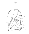
図1、2および3は、本発明に基づく空調措置1を横断面で示している。送風機ハウジング3の内部には、図示されていない送風機、好ましくはラジアルベンチレータが配置されており、それが切断面に対して垂直に空気を吸い込む。ラジアルベンチレータによって給送される空気は、まず空気フィルタ15を、そしてその後蒸発器4を貫流して、その蒸発器内で空気が冷却される。
1, 2 and 3 show in cross section an
蒸発器4の下流に、冷風通路と称される、流れ通路7と、発熱体流入通路と称される他の流れ通路6が接続されている。流れ通路6内へ流入する空気は、蒸発器4の下流側で熱交換機5を通過し、その熱交換機は発熱体として形成されている。たとえばPTCヒーターのような、選択的な補助ヒーターは、図示されていない。温風通路と称され、かつ発熱体の下流に位置する、流れ通路8を介して、暖められた空気が混合室9内へ達し、冷風通路7もこの混合室内へ連通している。
A
図1、2および3は、混合フラップ10を、第1の終端位置、第2の終端位置および中間位置で示している。混合フラップ10の調節が、第2の流れ通路8に対する第1の流れ通路7の開放された流れ断面の比とそれに伴って蒸発器4から来る体積流の割合を定め、その体積流は熱交換機5を介して案内されない。それによって混合室9内で得られる混合空気の、生じる温度が開ループ制御ないし閉ループ制御される。
1, 2 and 3 show the mixing
混合室9から複数の空気流出通路16が出ており、その場合にこれらの通路の各々に1つまたは複数の切替えフラップ(図には示されていない)が対応づけられており、その切替えフラップによって対応する空気流出通路16内の空気流の大きさが開ループ制御または閉ループ制御可能である。
A plurality of
図1において、混合フラップ10は第1の終端位置で示されており、その場合に混合フラップは冷風通路7を通る空気流の通路を閉鎖している。蒸発器4から来る全部の空気流が流れ通路6を介して熱交換機5へ、そしてさらに温風通路8を介して混合室9内へ案内される。混合フラップ10の第1の半径方向部分13が、蒸発器4の上方の端部に隣接した、ハウジング2の突出した領域に密着する。混合フラップ10の第2の半径方向部分13は、熱交換機5の上方の端部の領域内でハウジング2のウェブに添接する。半径方向部分13の端部の然るべきコーティングが、冷風通路7のほぼ空気密の閉鎖をもたらす。
In FIG. 1, the mixing
図2は、混合フラップ10を第2の終端位置で示しており、その場合に混合フラップは温風通路8を通る空気流の通過を閉鎖する。蒸発器4からくる全部の空気流は、冷風通路7を介して混合室9内へ案内される。混合フラップ10の第1の半径方向部分13は、熱交換機5の上方の端部に隣接して、ハウジング2の突出する領域に添接する。混合フラップ10の第2の半径方向部分13は、温風通路8の右の端部においてハウジング2のウェブに密着する。
FIG. 2 shows the mixing
図3には、混合フラップ10が中間位置で示されている。冷風通路7も温風通路8も完全には閉鎖されず、あるいは開放されない。記入されている矢印によって、蒸発器4から来る空気流の流れ方向が明らかにされている。その場合に空気流は、直接混合室9内へ達する第1の部分流と第2の部分流に分割され、第2の部分流は混合室9の壁領域を介して温風通路8内へ方向変換され、そこで熱交換機5を通過した部分流と混合される。図3から明らかなように、半径方向部分13と特に凹状の部分12の流れ的に好ましいように形成された形状によって、冷たい部分流のソフトな方向変換が可能である。
In FIG. 3, the mixing
図4aから4eには、混合フラップ10の実施形態の例が、横断面で示されている。
In FIGS. 4a to 4e, an example embodiment of a mixing
図4aは、部分12と13から構成された、混合フラップ10の壁領域を示している。終端部分13は、回転軸11から始まって半径方向に延びている。中央の部分12は、回転軸11に関して凹状の湾曲を有している。混合フラップ10の流れ特性を改良するために、半径方向部分13が持続的に凹状の部分12へ移行している。半径方向部分13は、混合フラップ10をその終端位置に固定するために、ハウジングに接するストッパとして用いられる。終端位置において流れ通路7と8のシールをもたらすために、混合フラップ10のストッパ面には、シールする材料、たとえば発泡吹付け被覆が設けられている。
FIG. 4 a shows the wall area of the mixing
図4bにおいて、部分13は直線的であるが、半径方向からはわずかな変位を有している。これは特に、湾曲の少ないプロフィールを備えた凹状の部分12を有する混合フラップ10にとって、部分13と12の間の接続領域において持続的な配置を満たすために、効果的である。
In FIG. 4b, the
混合フラップ10の開放ないし閉鎖運動の間に、暖かい空気と冷たい空気の所望の混合比のそれぞれの要請に適合させて、温風通路8内へ冷たい空気流を直接通過させるための横断面を所望に変化させるために、図4cに示すように、凹状の壁部分12は非対称の延びを有することもできる。
Desirable cross-section for passing cold air flow directly into the hot air passage 8 in accordance with the respective requirements of the desired mixing ratio of warm air and cold air during the opening or closing movement of the mixing
ほぼ凹状の湾曲推移に近づけることは、たとえば図4dに示すように、まっすぐな部分12を互いに連ねることによっても達成される。その場合に極端な場合には、図4eに示すように、まっすぐな部分2を有する三角形フラップの形状が得られる。
Approaching a substantially concave curve transition can also be achieved by connecting
図5は、側方においてフラップ10の前側に取り付けられた揺動アーム14を有する混合フラップ10を斜視図で示しており、その場合に揺動アーム14は半径方向に拡幅しており、混合フラップ10の回転軸11から壁領域へ延びるウェブの形状で形成されている。
FIG. 5 shows in a perspective view the
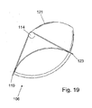
部分領域のみにおいて回転軸に関して凹状の、本発明に基づく壁領域117を有する、混合フラップ106を備えた自動車空調設備101が、図6から19で説明される。
An
幾つかに分かれて形成された空気ガイドハウジング107内に配置されている、送風機102、蒸発器103、ヒーター104および補助ヒーター105を有するこの自動車空調設備101は、必要に応じて温度調節し、かつ層状化された空気流を発生させるために、混合フラップ106を有している。
This automobile
温度調節された空気は、フラップによって制御される空気通路を介して車両室内の種々の領域へ供給することができる。すなわち、空気ガイドハウジング107から分岐する空気通路108が設けられており、それはフロントガラスのデフロストに用いられる。デフロスト通路108を通って案内される空気量は、デフロストフラップ109によって制御される。他の空気通路110が側方および中央のノズルへ通じており、フラップ111によって制御可能である。さらに、足下空間空気通路112が設けられており、それは足下空間フラップ113によって制御可能である。
Temperature-controlled air can be supplied to various areas within the vehicle compartment via air passages controlled by flaps. That is, an
図6から明らかなように、換気−空気通路110は、3つの部分で形成されており、その場合にここでは3つの部分通路はそれぞれほぼ等しい横断面を有している。それらは、中央ノズルと側方ノズルの間でフラップ106と協働して、空気を層状にするために用いられる。
As is apparent from FIG. 6, the ventilation-
この空気の層状化を、仕切壁または特殊に形成された冷風通路を必要とせず、従ってより少ない組込み空間需要を有する、単純なフラップによって可能にするために、上述した実施例によれば、3部材のフラップ106が設けられている。このフラップは、その揺動軸内に2本のピン114を有しており、それらのピンは前面115に配置されている。フラップ106は、フラップ106の中央に、揺動軸に対して垂直に延びる平面に関して鏡対称に形成されており、その場合にフラップ106を有するこの平面の切断線が、図17に示されている。
In order to allow this air stratification by means of a simple flap, which does not require partitions or specially formed cold air passages and thus has less built-in space demand, according to the embodiment described above, 3 A
フラップ106は、それが対称であることに基づいて、2つの外側の領域116と中央の領域117を有している。フラップは、その外側の領域116においてドラムフラップ状に形成されており、すなわちフラップ106は中空円筒の部分の形状を有している。領域116と117は、フラップ106の長手方向に延びる側118において、等しい高さを有しており、その場合にシールを改良するために半径方向外側へ向かって延びる端縁119が設けられており、その端縁は前面115も越えてピン114まで延びている。2つの外側の領域116の流れ断面は合わせて、本実施例によれば、中央の領域117の流れ断面にほぼ相当する。
The
中央の領域117は、揺動軸の方向へ湾曲して形成されており、かつ側方の領域116から壁120によって分離されている。壁120の揺動軸側の端部において、壁はブリッジ121によって結合されており、その場合にこのブリッジは中央の領域117と同様にやや湾曲されている。このブリッジ121は、一方では、空気案内機能を有する、一種のスポイラーとして、他方ではフラップ106の安定性を向上させるために用いられる。
The
フラップ106の、側方118とは反対の側122においては、特に図18から明らかなように、領域116と117は異なる高さを有している。開放行動を改良するために、外側の領域116は斜めに形成されており、すなわちその領域は特に揺動軸に対して平行には延びていない。中央の領域117は、揺動軸に対して平行に終了しており、その場合にここでも外側へ延びる端縁123が設けられており、その端縁は外側の領域116の外側、前面115も越えて、ピン114まで、従って端縁119まで延びている。
On the
次に、フラップ106の機能を、図8から15を参照して詳細に説明する。
Next, the function of the
図8と9は、100%温の位置、すなわちフラップ106が直接蒸発器103から来る冷風に、すべての領域116と117を有するルートを閉鎖する。その場合にフラップ106の端縁119が、それに応じて形成された空気ガイドハウジング107に添接するので、冷たい空気は空気通路108と112へ達することができない。ヒーター104および補助ヒーター105から来る温風の流れルートは、デフロストフラップおよび足下空間フラップ109と113が開放されている場合について、実線の矢印で示されている。側方および中央のノズルへの空気供給のためのフラップ111は、表示のように閉鎖されている。
FIGS. 8 and 9 close the route with all
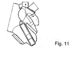
図10と11に示すように、フラップ106がゆっくりとその他方の終端位置へ移動された場合に、フラップ106の中央の領域117内の両側で冷風通路が解放され、その冷風通路を通って冷たい空気が特にデフロスト空気通路108内へ流入する。それによって、足下空間へ案内される空気の温度が、デフロスト空気通路108内へ達する空気の温度よりも高くなることが達成される。外側の領域116が幅広く形成されていることに基づいて、この領域内への冷風通路はまだ閉鎖されている。冷風の流れルートは、図では点線の矢印で示されている。
As shown in FIGS. 10 and 11, when the
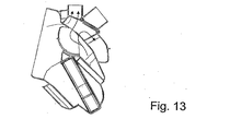
図12と13に示すように、フラップ106がさらに移動した場合に、中央の領域117の冷風通路がさらに開放されるので、温度がさらに低下する。外側の領域116内では、冷風通路が、斜めになっていることによってゆっくりと開放し始め、冷風が外側の領域116内の、特にデフロスト空気通路108へ達する。ここでも、足下空間内へ案内される空気の温度が、デフロスト空気通路108内へ達する空気の温度よりも高いことにより、乗客にとって心地よいと感じられる温度層状化が得られる。
As shown in FIGS. 12 and 13, when the
空気通路110の開放または少なくとも部分的な開放をもたらすフラップ位置において(図8から13には示されていない)、中央と側方の空気通路間で温度層状化が得られる。フラップ106の上述した形状によって、1つまたは複数の中央ノズルへ供給される空気の温度は、側方ノズル内の空気温度よりも低く、それも同様に室内の快適性向上に寄与する。というのは、サイドガラス窓を介しての熱放射は、客室の中央におけるよりも大きく、かつ上述した温度の層状化によって、少なくとも乗客が感じる、温度プロフィールの均一化をもたらす。
In the flap position (not shown in FIGS. 8 to 13) resulting in opening or at least partial opening of the
図14と15に示すように、温風通路が完全に閉鎖されている場合には、全領域116と117内で対応する空気通路108、110および112へ冷風が達する。その場合に図示の実施例において、デフロスト空気通路109も足下空間への空気通路112も閉鎖されており、冷たい空気のみが均一に側方ノズルと中央ノズルのための通路110内へ達する。
As shown in FIGS. 14 and 15, when the hot air passage is completely closed, the cool air reaches the corresponding
従って空気の層状化を可能にすることができ、その場合にフラップ6の混合位置または中間位置全体において、フロントガラスへ供給される空気は、足下空間へ供給される空気よりも冷たく、ないしは中央ノズルへ供給される空気は、側方ノズルへ供給される空気よりも冷たい。 Air can therefore be stratified, in which case the air supplied to the windshield is colder than the air supplied to the foot space or the central nozzle in the mixing or intermediate position of the flap 6 The air supplied to is cooler than the air supplied to the side nozzles.
適切な所望の温度の層状化を得るために、他の実施例においては、3つに分かれた混合フラップが設けられており、その混合フラップにおいては、2つの外側の領域は凸状に湾曲されており、かつバイパス通路内へ案内される。その間に位置する領域は、本発明に基づく壁領域の、回転軸に対して凹状の湾曲を有している。この実施例を、図20から23を用いて、以下で詳細に説明する。フラップの2つの外側の領域は、以下においては混合フラップと称され、内側の領域は切替えフラップと称される。 In order to obtain a suitable desired temperature stratification, in another embodiment, three separate mixing flaps are provided, in which the two outer regions are convexly curved. And is guided into the bypass passage. The area located between them has a concave curvature with respect to the axis of rotation of the wall area according to the invention. This embodiment will be described in detail below with reference to FIGS. The two outer regions of the flap are hereinafter referred to as mixing flaps and the inner region is referred to as a switching flap.
図20a、20b;21a、21b;22a、22bの3対の図は、それぞれ本発明に基づく空調装置の断面を示している。その場合にaで示す図は、常に、バイパス通路の外部の領域を通る断面を示し、bで示される図はバイパス通路の領域の断面を示しており、その場合に同じ対の図のフラップ位置は、互いに相当する。空調装置内のバイパス通路の位置は、選択可能である。1つより多いバイパス通路を設けることもでき、その場合に各バイパス通路は混合フラップを有している。その場合にバイパス通路は、特に空調装置の片側または両側の横方向に、あるいは中央に形成することができる。 The three pairs of figures 20a, 20b; 21a, 21b; 22a, 22b each show a cross section of an air conditioner according to the invention. In that case, the figure indicated by a always shows a cross section through the region outside the bypass passage, and the figure indicated by b shows a cross section in the region of the bypass passage, in which case the flap position of the same pair of figures Are equivalent to each other. The position of the bypass passage in the air conditioner can be selected. There can also be more than one bypass passage, in which case each bypass passage has a mixing flap. In this case, the bypass passage can be formed in the lateral direction on one or both sides of the air conditioner, or in the center.
対の図20から22は、空調装置210を横断面で示している。送風機ハウジング211の内部には、図示されていない送風機、ラジアルベンチレータが配置されており、それが切断平面に対して垂直に空気を吸い込む。
The pair of FIGS. 20 to 22 shows the
ラジアルベンチレータによって給送される空気は、まず空気フィルタ212を、そしてその後蒸発器213を貫流し、その蒸発器内で空気が冷却される。蒸発器213の下流側に、分配室214が接続されている。バイパス通路230がその中に延びている領域内で、バイパス通路220の壁231が第1の流れ通路215をスリット232へ至るまで閉鎖しており、そのスリットを通して混合フラップ233が案内され、その場合に漏れ流を防止するために、案内を流体密にすることができる。バイパス通路の隣りの領域において、第1の流れ通路215は直接混合室218内へ通じている。
The air delivered by the radial ventilator flows first through the
第2の流れ通路216は、分配室214から熱交換機217を介して混合室218内へ通じている。3対の図において異なる位置、2つの終端位置と中間位置で示される切替えフラップ234が、その位置によって、第2の流れ通路216に対する第1の流れ通路215の開放された流れ断面の比とそれに伴って蒸発器213から来る、熱交換機213を介して案内されない体積流の割合を定める。従って混合室216内で得られる混合空気の、生じる温度が開ループ制御ないし閉ループ制御される。
The
混合室218からは、複数の空気流出通路219が出ており、その場合にこれらの通路の各々に切替えフラップ220が対応づけられており、その切替えフラップによって該当する空気流出通路219内への空気流の大きさが開ループ制御または閉ループ制御可能である。車両内で温度の層状化を得るために、空気通路219は、第1の流れ通路215からの空気と第2の流れ通路216からの空気の間の様々な混合比を有する箇所で分岐しているので、混合流の様々な温度が与えられる。
A plurality of
空気流出通路の1つは、いわゆるデフロスト通路221である。これは、デフロストノズルへ通じており、そのデフロストノズルは直接車両の窓ガラスの領域、特にフロントガラスの領域に配置されており、窓ガラスを迅速に加熱し、ないしは窓ガラスから復水した水滴による曇りを除去するために用いられる。その場合にデフロスト通路221は、第1の流れ通路からの空気の高い割合を有し、従って比較的冷たい箇所で分岐している。しかしこれは、加熱および曇り除去機能にとっては障害であるが、構造に基づいている。従ってバイパス通路230が設けられており、それが第2の流れ通路216内で分岐し、デフロスト通路221内で該当する切替えフラップ221のすぐ前で開口している。それによってデフロスト通路221内の空気流により高い温風割合が供給される。その場合に混合フラップ233の位置を介して、デフロスト通路221を通る体積流を変化させることができる。というのは、自由な流れ断面が混合フラップ位置に依存しているからである。その場合に、デフロスト通路221に対応づけられた切替えフラップ220は、デフロスト通路221を通る体積流の大きさを制御するが、その中のバイパス通路230からの体積流の割合は制御しない。
One of the air outflow passages is a so-called defrost passage 221. This leads to a defrost nozzle, which is located directly in the window glass area of the vehicle, in particular in the windshield area, which heats the window glass quickly or by water drops condensing from the window glass. Used to remove haze. In that case, the defrost passage 221 has a high proportion of air from the first flow passage and therefore branches off at a relatively cool spot. However, this is a hindrance to the heating and defogging functions, but is based on structure. A
その場合に図示の実施形態においては、混合フラップ233と切替えフラップ234は共通の揺動軸235上に配置されており、その場合にフラップは湾曲された表面237を有し、かつ半径方向に拡幅する揺動アーム236を介して揺動軸235に添接している。その場合に揺動アーム236は、少なくとも部分的に閉鎖された側面を有しており、その側面がバイパス通路230と第1の流れ通路215の間の仕切機能を有している。従って混合フラップ233の位置が直接切替えフラップ234の位置に結合されており、これらは共に、図20から22に示すように、操作部材238によって揺動軸がハウジングに対して回動することによって、位置を変化させることができる。
In that case, in the illustrated embodiment, the mixing
図20aと20bに示すように、第1の流れ通路215が閉鎖されている場合には、全空気流が熱交換機217を介して案内されて、そこで加熱される。その場合にバイパス通路230が最大に開放されており、高い体積流割合の温風がデフロスト通路221へ供給される。これが、デフロスト通路221内の比較的高い空気温度と、対応づけられた窓ガラスないしフロントガラスのできる限り迅速な加熱とそれに伴って曇りと霜のない窓ガラスをもたらす。
As shown in FIGS. 20a and 20b, when the first flow passage 215 is closed, the entire air flow is guided through the heat exchanger 217 and heated there. In this case, the
図22aと22bに示すように、第2の流れ通路215が開放されている場合には、全空気流が第1の流れ通路215を介して、従って熱交換機217を迂回して案内される。その場合にバイパス通路230は閉鎖されており、デフロスト通路221へはバイパス通路230からの暖かい空気は供給されない。それが、デフロスト通路221内の比較的低い空気温度と、室内の迅速な冷却をもたらし、かつ車両室内の好ましい空気の層状化が促進される。
As shown in FIGS. 22a and 22b, when the second flow passage 215 is open, the entire air flow is guided through the first flow passage 215 and thus bypassing the heat exchanger 217. In this case, the
図21aと21bに示す中間位置において、それぞれ部分流が発生される。従ってバイパス通路230を介してわずかな温風体積流がデフロスト通路221へ案内され、このデフロスト通路はそうでない場合にデフロスト通路を貫流する空気に対して高い温度を有するが、バイパス通路が自由に貫流可能である時ほど強くは加熱されない。それによってデフロスト通路221に対応づけられた窓ガラスの領域内に暖められた空気が供給されるが、その空気は車両内の温度の層状化を不必要に強く乱さない。加熱の程度は、所望の温度変化の強さによって調節され、その温度変化に基づいて切替えフラップ234の位置が定められる。
A partial flow is generated at each intermediate position shown in FIGS. 21a and 21b. Accordingly, a small volume of warm air is guided through the
図23は、混合フラップ233と切替えフラップ234を一体化したフラップ部材を斜視図で示している。その場合に混合フラップセグメント233は凸状に湾曲されており、切替えフラップ部材234は凹状に湾曲されている。切替えフラップセグメント234と混合フラップセグメント233の間の楕円形のレンズが壁231を形成しており、その壁はこの領域においてバイパス通路230と第1の流れ通路215の間の流体的な分離をもたらし、その領域内にバイパス通路230内のスリット231も延びている。その場合にこの壁を、半径方向外側へ向かって広がる揺動アーム236の一部とすることもできる。しかし、図示の実施形態においては、揺動軸はそれとは別に形成されたウェブとして実現されている。その場合に図23は、2つの横方向に配置されたバイパス通路231を有しており、それらがそれぞれ混合フラップ233を有しており、その場合にその間に第1の流れ通路216が延びており、それがその中に配置されている2つの切替えフラップ234によって閉鎖可能である。その場合に、フラップの操作運動の発生を担当する操作部材238が、この図では破線で示されている。その場合に操作部材238は、然るべき制御ユニットによって駆動され、その制御ユニットによって本発明に基づく方法も実施される。
FIG. 23 is a perspective view of a flap member in which the
1 空調措置
2 ハウジング
3、211 送風機ハウジング
4、103、213 蒸発器
5、217 熱交換機
6 流れ通路
7、215 第1の流れ通路
8、216 第2の流れ通路
9、218 混合室
10、106、233 混合フラップ
11 回転軸
13 半径方向部分
14、236 揺動アーム
15、212 空気フィルタ
16、219 空気流出通路
101 自動車空調設備
102 送風機
104 ヒーター
105 補助ヒーター
107 空気ガイドハウジング
108、221 デフロスト通路
109 デフロストフラップ
110 空気通路
114 ピン
116、117 領域
120 壁
121 ブリッジ
210 空調装置
214 分配室
230 バイパス通路
232 スリット
235 揺動軸
DESCRIPTION OF
Claims (10)
・送風機の下流側に配置された、空気流によって貫流される蒸発器と、
・蒸発器の後段に配置された混合フラップと、
を有し、
・空気流が混合フラップによって第1の流れ通路および/または第2の流れ通路へ分割可能であって、それによって第1および/または第2の部分空気流が発生可能であり、
・第1の流れ通路(冷風通路)が混合室内へ連通し、
・第2の流れ通路(温風通路)内には第2の部分空気流を加熱するための熱交換機が配置されており、かつ第2の流れ通路が熱交換機の下流側で混合室内へ連通しており、
・混合室内で第1と第2の部分空気流から混合空気流が形成可能であって、その場合に混合室から空気流出通路が車両室内の様々な領域へ通じており、
・かつ、混合フラップが回転軸を中心に、第1の流れ通路を完全に閉鎖する第1の終端位置と、第2の流れ通路を完全に閉鎖する第2の終端位置の間で揺動可能であって、かつその間にある位置においては、第1の流れ通路から第2の流れ通路への冷風の直接的な通過を可能にする、車両用空調装置において、
混合フラップが空気流を分割するために、少なくとも3つの部分からなり、かつ回転軸がこれらの部分の外側に位置し、第1の部分は回転軸に関して半径方向に、または少なくとも半径方向に対して鋭角で、第2の部分は回転軸に関して凹状に、そして第3の部分は回転軸に関して半径方向に、あるいは少なくとも半径方向に対して鋭角で配置されて、第1と第3の部分が第2の部分の両側の端部に、3つの部分がつながった輪郭を有する壁領域を形成するように、接続されていることを特徴とする、車両用空調装置。 A blower for generating an air flow;
An evaporator arranged on the downstream side of the blower, which flows through by the air flow;
A mixing flap placed after the evaporator;
Have
The air flow can be divided into a first flow path and / or a second flow path by means of a mixing flap, whereby a first and / or a second partial air flow can be generated;
The first flow passage (cold air passage) communicates with the mixing chamber,
A heat exchanger for heating the second partial air flow is disposed in the second flow passage (warm air passage), and the second flow passage communicates with the mixing chamber on the downstream side of the heat exchanger. And
A mixed air flow can be formed from the first and second partial air flows in the mixing chamber, in which case the air outflow passage leads from the mixing chamber to various regions in the vehicle compartment,
-And the mixing flap can swing between a first end position that completely closes the first flow passage and a second end position that completely closes the second flow passage about the rotation axis And in a vehicle air conditioner that allows direct passage of cold air from the first flow passage to the second flow passage at a position in between,
The mixing flap consists of at least three parts for dividing the air flow and the axis of rotation is located outside these parts, the first part being radially with respect to the axis of rotation or at least with respect to the radial direction At an acute angle, the second part is concave with respect to the axis of rotation and the third part is arranged radially with respect to the axis of rotation, or at least at an acute angle with respect to the radial direction, the first and third parts being the second An air conditioner for a vehicle, characterized in that it is connected to end portions on both sides of this portion so as to form a wall region having a contour in which three portions are connected.
10. The mixing flap according to any one of claims 1 to 9, characterized in that the mixing flap is linked to the rocking shaft via a rocking arm which is widened in the shape of a circular segment, preferably arranged with fixed edges. The air conditioner described in 1.
Applications Claiming Priority (3)
| Application Number | Priority Date | Filing Date | Title |
|---|---|---|---|
| DE10329582 | 2003-06-30 | ||
| DE102004008862 | 2004-02-20 | ||
| PCT/EP2004/006635 WO2005000612A1 (en) | 2003-06-30 | 2004-06-18 | Air-conditioning system for vehicles |
Publications (1)
| Publication Number | Publication Date |
|---|---|
| JP2007506601A true JP2007506601A (en) | 2007-03-22 |
Family
ID=33553477
Family Applications (1)
| Application Number | Title | Priority Date | Filing Date |
|---|---|---|---|
| JP2006516003A Pending JP2007506601A (en) | 2003-06-30 | 2004-06-18 | Air conditioner for vehicles |
Country Status (6)
| Country | Link |
|---|---|
| US (1) | US20090209189A1 (en) |
| EP (1) | EP1641643B1 (en) |
| JP (1) | JP2007506601A (en) |
| AT (1) | ATE383963T1 (en) |
| DE (2) | DE502004005970D1 (en) |
| WO (1) | WO2005000612A1 (en) |
Cited By (1)
| Publication number | Priority date | Publication date | Assignee | Title |
|---|---|---|---|---|
| WO2016088338A1 (en) * | 2014-12-05 | 2016-06-09 | 株式会社デンソー | Vehicular air-conditioning unit |
Families Citing this family (11)
| Publication number | Priority date | Publication date | Assignee | Title |
|---|---|---|---|---|
| US20070187520A1 (en) * | 2006-02-13 | 2007-08-16 | Hall Timothy J | Multi-zone temperature control module for an air handling system of a heating, ventilation, and air conditioning system for a vehicle |
| JP2008062659A (en) * | 2006-09-04 | 2008-03-21 | Japan Climate Systems Corp | Vehicular air conditioner |
| DE102007036824B4 (en) * | 2007-08-03 | 2020-06-18 | Mahle International Gmbh | Flap arrangement, in particular for a vehicle air conditioning system, for regulating an air flow |
| US9610823B2 (en) * | 2008-09-25 | 2017-04-04 | Mahle International Gmbh | Vehicle HVAC temperature control system |
| US8721408B2 (en) * | 2009-11-18 | 2014-05-13 | Keihin Corporation | Air conditioner for vehicle |
| DE102010031475A1 (en) * | 2010-07-16 | 2012-01-19 | Behr Gmbh & Co. Kg | Air mixing door assembly |
| DE102011005181A1 (en) * | 2011-03-07 | 2012-09-13 | Behr Gmbh & Co. Kg | Air deflection element with a flow-optimized contour for an air conditioning system |
| DE102013227046A1 (en) * | 2013-12-20 | 2015-06-25 | MAHLE Behr GmbH & Co. KG | Air conditioning, in particular for a motor vehicle |
| US20150345810A1 (en) * | 2014-05-30 | 2015-12-03 | Denso International America, Inc. | Dual layer door |
| DE102019219537A1 (en) * | 2019-12-13 | 2021-06-17 | Mahle International Gmbh | Adjustment flap arrangement and channel arrangement |
| DE102019219535A1 (en) * | 2019-12-13 | 2021-06-17 | Mahle International Gmbh | Closure element arrangement and channel arrangement with closure element arrangement |
Citations (3)
| Publication number | Priority date | Publication date | Assignee | Title |
|---|---|---|---|---|
| JPS4938914Y1 (en) * | 1969-07-25 | 1974-10-25 | ||
| JPS609720U (en) * | 1983-06-30 | 1985-01-23 | 三菱自動車工業株式会社 | Automotive air conditioner |
| JP2000203238A (en) * | 1998-12-22 | 2000-07-25 | Valeo Climatisation | Heating/air conditioning system for automobile |
Family Cites Families (15)
| Publication number | Priority date | Publication date | Assignee | Title |
|---|---|---|---|---|
| DE3038272C2 (en) | 1980-10-10 | 1985-03-07 | Süddeutsche Kühlerfabrik Julius Fr. Behr GmbH & Co KG, 7000 Stuttgart | Air distribution and control device for a motor vehicle heating system |
| FR2547543B1 (en) * | 1983-06-20 | 1987-10-16 | Valeo | HOUSING OF A HEATING OR AIR CONDITIONING SYSTEM FOR A MOTOR VEHICLE |
| DE3510991A1 (en) | 1985-03-27 | 1986-10-09 | Süddeutsche Kühlerfabrik Julius Fr. Behr GmbH & Co KG, 7000 Stuttgart | Device for heating and/or air-conditioning a motor vehicle interior |
| DE3826182C1 (en) * | 1988-08-02 | 1989-10-26 | Adam Opel Ag, 6090 Ruesselsheim, De | Heating and ventilating device for the passenger compartment of motor vehicles |
| DE9110870U1 (en) * | 1990-09-13 | 1991-10-24 | Siemens Ag, 8000 Muenchen, De | |
| DE4305253C2 (en) * | 1993-02-20 | 2000-09-21 | Opel Adam Ag | Heating and ventilation device |
| FR2715352B1 (en) * | 1994-01-24 | 1996-04-19 | Valeo Thermique Habitacle | Heating and ventilation device for the passenger compartment of a motor vehicle. |
| FR2765526B1 (en) * | 1997-07-01 | 2002-01-11 | Valeo Climatisation | HEATING AND / OR AIR CONDITIONING INSTALLATION, ESPECIALLY A MOTOR VEHICLE, EQUIPPED WITH AN AIR TREATMENT HOUSING WITH IMPROVED AIR DISTRIBUTION |
| US6453991B1 (en) * | 1999-03-29 | 2002-09-24 | Calsonickansei Corporation | Automotive air conditioner |
| FR2796335B1 (en) * | 1999-07-12 | 2001-10-05 | Valeo Climatisation | HEATING SYSTEM, ESPECIALLY A TYPE OF AIR CONDITIONING HAVING A MIXING SHUTTER |
| JP4160215B2 (en) * | 1999-09-29 | 2008-10-01 | カルソニックカンセイ株式会社 | Air conditioner for vehicles |
| DE10031991B4 (en) * | 2000-06-30 | 2004-02-05 | Valeo Klimasysteme Gmbh | damper |
| FR2822107B1 (en) * | 2001-03-19 | 2012-03-23 | Denso Corp | AIR CONDITIONER FOR VEHICLES HAVING RIGHT STEERING WHEEL AND LEFT STEERING WHEEL |
| JP4089390B2 (en) * | 2002-11-05 | 2008-05-28 | 株式会社デンソー | Air conditioner for vehicles |
| FR2862911B1 (en) * | 2003-11-28 | 2006-03-03 | Valeo Climatisation | DEVICE FOR HEATING-VENTILATION AND / OR AIR CONDITIONING OF A VEHICLE HABITACLE WITH ZONE TEMPERATURE ADJUSTMENT |
-
2004
- 2004-06-18 WO PCT/EP2004/006635 patent/WO2005000612A1/en active Application Filing
- 2004-06-18 JP JP2006516003A patent/JP2007506601A/en active Pending
- 2004-06-18 DE DE502004005970T patent/DE502004005970D1/en active Active
- 2004-06-18 AT AT04763009T patent/ATE383963T1/en not_active IP Right Cessation
- 2004-06-18 US US10/562,709 patent/US20090209189A1/en not_active Abandoned
- 2004-06-18 EP EP04763009A patent/EP1641643B1/en not_active Not-in-force
- 2004-06-18 DE DE102004029477A patent/DE102004029477A1/en not_active Withdrawn
Patent Citations (3)
| Publication number | Priority date | Publication date | Assignee | Title |
|---|---|---|---|---|
| JPS4938914Y1 (en) * | 1969-07-25 | 1974-10-25 | ||
| JPS609720U (en) * | 1983-06-30 | 1985-01-23 | 三菱自動車工業株式会社 | Automotive air conditioner |
| JP2000203238A (en) * | 1998-12-22 | 2000-07-25 | Valeo Climatisation | Heating/air conditioning system for automobile |
Cited By (3)
| Publication number | Priority date | Publication date | Assignee | Title |
|---|---|---|---|---|
| WO2016088338A1 (en) * | 2014-12-05 | 2016-06-09 | 株式会社デンソー | Vehicular air-conditioning unit |
| JP2016107799A (en) * | 2014-12-05 | 2016-06-20 | 株式会社デンソー | Air conditioning unit for vehicle |
| CN107000539A (en) * | 2014-12-05 | 2017-08-01 | 株式会社电装 | Vehicular air-conditioning unit |
Also Published As
| Publication number | Publication date |
|---|---|
| ATE383963T1 (en) | 2008-02-15 |
| US20090209189A1 (en) | 2009-08-20 |
| EP1641643A1 (en) | 2006-04-05 |
| WO2005000612A1 (en) | 2005-01-06 |
| DE502004005970D1 (en) | 2008-03-06 |
| DE102004029477A1 (en) | 2005-03-31 |
| EP1641643B1 (en) | 2008-01-16 |
Similar Documents
| Publication | Publication Date | Title |
|---|---|---|
| US7540321B2 (en) | Air conditioner for vehicle | |
| JP2001058511A (en) | Air conditioner for automobile | |
| CA2883493C (en) | Vehicle air conditioner | |
| JP2007506601A (en) | Air conditioner for vehicles | |
| EP3363665B1 (en) | Air conditioning device for vehicle | |
| JP2000335224A (en) | Heater or air conditioner for vehicle cabin | |
| JP2001138724A (en) | Air conditioner for vehicle | |
| JP2000326721A (en) | Air conditioning unit and vehicular air conditioner | |
| JPH11208245A (en) | Vehicle air condiioner | |
| JP2004230995A (en) | Air conditioner for vehicle | |
| KR102065967B1 (en) | Multi-planar air diverter. | |
| WO2020179446A1 (en) | Vehicle air-conditioning device | |
| US11351840B2 (en) | Air conditioner for vehicle | |
| JP4516570B2 (en) | Air conditioning mechanism for vehicles and method for operating the air conditioning mechanism | |
| JP2000033814A (en) | Air conditioner for vehicle | |
| JPH10203133A (en) | Air-conditioning device for automobile | |
| JP2000108636A (en) | Air conditioner for automobile | |
| US20080256965A1 (en) | Heating And/Or Air Conditioning Unit For Vehicles | |
| JP2003285624A (en) | Vehicular air conditioner | |
| JP5293590B2 (en) | Air conditioner for vehicles | |
| JP2001287534A (en) | Vehicular air conditioner | |
| JP2000296712A (en) | Air conditioner for vehicle | |
| JP3997959B2 (en) | Air conditioner for vehicles | |
| JP3564410B2 (en) | Vehicle air conditioner | |
| JP4264220B2 (en) | Air conditioning unit |
Legal Events
| Date | Code | Title | Description |
|---|---|---|---|
| A621 | Written request for application examination |
Free format text: JAPANESE INTERMEDIATE CODE: A621 Effective date: 20070412 |
|
| A131 | Notification of reasons for refusal |
Free format text: JAPANESE INTERMEDIATE CODE: A131 Effective date: 20091027 |
|
| A02 | Decision of refusal |
Free format text: JAPANESE INTERMEDIATE CODE: A02 Effective date: 20100413 |