JP2007504876A - Spatial ultrasound compound with simultaneous transmission of multiple beams - Google Patents
Spatial ultrasound compound with simultaneous transmission of multiple beams Download PDFInfo
- Publication number
- JP2007504876A JP2007504876A JP2006525929A JP2006525929A JP2007504876A JP 2007504876 A JP2007504876 A JP 2007504876A JP 2006525929 A JP2006525929 A JP 2006525929A JP 2006525929 A JP2006525929 A JP 2006525929A JP 2007504876 A JP2007504876 A JP 2007504876A
- Authority
- JP
- Japan
- Prior art keywords
- beams
- transmit
- imaging system
- diagnostic imaging
- receive
- Prior art date
- Legal status (The legal status is an assumption and is not a legal conclusion. Google has not performed a legal analysis and makes no representation as to the accuracy of the status listed.)
- Granted
Links
Images


Classifications
-
- G—PHYSICS
- G01—MEASURING; TESTING
- G01S—RADIO DIRECTION-FINDING; RADIO NAVIGATION; DETERMINING DISTANCE OR VELOCITY BY USE OF RADIO WAVES; LOCATING OR PRESENCE-DETECTING BY USE OF THE REFLECTION OR RERADIATION OF RADIO WAVES; ANALOGOUS ARRANGEMENTS USING OTHER WAVES
- G01S7/00—Details of systems according to groups G01S13/00, G01S15/00, G01S17/00
- G01S7/52—Details of systems according to groups G01S13/00, G01S15/00, G01S17/00 of systems according to group G01S15/00
- G01S7/52017—Details of systems according to groups G01S13/00, G01S15/00, G01S17/00 of systems according to group G01S15/00 particularly adapted to short-range imaging
- G01S7/52085—Details related to the ultrasound signal acquisition, e.g. scan sequences
- G01S7/5209—Details related to the ultrasound signal acquisition, e.g. scan sequences using multibeam transmission
- G01S7/52093—Details related to the ultrasound signal acquisition, e.g. scan sequences using multibeam transmission using coded signals
-
- G—PHYSICS
- G01—MEASURING; TESTING
- G01S—RADIO DIRECTION-FINDING; RADIO NAVIGATION; DETERMINING DISTANCE OR VELOCITY BY USE OF RADIO WAVES; LOCATING OR PRESENCE-DETECTING BY USE OF THE REFLECTION OR RERADIATION OF RADIO WAVES; ANALOGOUS ARRANGEMENTS USING OTHER WAVES
- G01S15/00—Systems using the reflection or reradiation of acoustic waves, e.g. sonar systems
- G01S15/88—Sonar systems specially adapted for specific applications
- G01S15/89—Sonar systems specially adapted for specific applications for mapping or imaging
- G01S15/8906—Short-range imaging systems; Acoustic microscope systems using pulse-echo techniques
- G01S15/8995—Combining images from different aspect angles, e.g. spatial compounding
-
- G—PHYSICS
- G01—MEASURING; TESTING
- G01S—RADIO DIRECTION-FINDING; RADIO NAVIGATION; DETERMINING DISTANCE OR VELOCITY BY USE OF RADIO WAVES; LOCATING OR PRESENCE-DETECTING BY USE OF THE REFLECTION OR RERADIATION OF RADIO WAVES; ANALOGOUS ARRANGEMENTS USING OTHER WAVES
- G01S7/00—Details of systems according to groups G01S13/00, G01S15/00, G01S17/00
- G01S7/52—Details of systems according to groups G01S13/00, G01S15/00, G01S17/00 of systems according to group G01S15/00
- G01S7/52017—Details of systems according to groups G01S13/00, G01S15/00, G01S17/00 of systems according to group G01S15/00 particularly adapted to short-range imaging
- G01S7/52046—Techniques for image enhancement involving transmitter or receiver
-
- G—PHYSICS
- G01—MEASURING; TESTING
- G01S—RADIO DIRECTION-FINDING; RADIO NAVIGATION; DETERMINING DISTANCE OR VELOCITY BY USE OF RADIO WAVES; LOCATING OR PRESENCE-DETECTING BY USE OF THE REFLECTION OR RERADIATION OF RADIO WAVES; ANALOGOUS ARRANGEMENTS USING OTHER WAVES
- G01S7/00—Details of systems according to groups G01S13/00, G01S15/00, G01S17/00
- G01S7/52—Details of systems according to groups G01S13/00, G01S15/00, G01S17/00 of systems according to group G01S15/00
- G01S7/52017—Details of systems according to groups G01S13/00, G01S15/00, G01S17/00 of systems according to group G01S15/00 particularly adapted to short-range imaging
- G01S7/52085—Details related to the ultrasound signal acquisition, e.g. scan sequences
- G01S7/52095—Details related to the ultrasound signal acquisition, e.g. scan sequences using multiline receive beamforming
-
- G—PHYSICS
- G01—MEASURING; TESTING
- G01S—RADIO DIRECTION-FINDING; RADIO NAVIGATION; DETERMINING DISTANCE OR VELOCITY BY USE OF RADIO WAVES; LOCATING OR PRESENCE-DETECTING BY USE OF THE REFLECTION OR RERADIATION OF RADIO WAVES; ANALOGOUS ARRANGEMENTS USING OTHER WAVES
- G01S15/00—Systems using the reflection or reradiation of acoustic waves, e.g. sonar systems
- G01S15/88—Sonar systems specially adapted for specific applications
- G01S15/89—Sonar systems specially adapted for specific applications for mapping or imaging
- G01S15/8906—Short-range imaging systems; Acoustic microscope systems using pulse-echo techniques
- G01S15/8959—Short-range imaging systems; Acoustic microscope systems using pulse-echo techniques using coded signals for correlation purposes
-
- G—PHYSICS
- G01—MEASURING; TESTING
- G01S—RADIO DIRECTION-FINDING; RADIO NAVIGATION; DETERMINING DISTANCE OR VELOCITY BY USE OF RADIO WAVES; LOCATING OR PRESENCE-DETECTING BY USE OF THE REFLECTION OR RERADIATION OF RADIO WAVES; ANALOGOUS ARRANGEMENTS USING OTHER WAVES
- G01S7/00—Details of systems according to groups G01S13/00, G01S15/00, G01S17/00
- G01S7/52—Details of systems according to groups G01S13/00, G01S15/00, G01S17/00 of systems according to group G01S15/00
- G01S7/52017—Details of systems according to groups G01S13/00, G01S15/00, G01S17/00 of systems according to group G01S15/00 particularly adapted to short-range imaging
- G01S7/52023—Details of receivers
- G01S7/52034—Data rate converters
-
- G—PHYSICS
- G01—MEASURING; TESTING
- G01S—RADIO DIRECTION-FINDING; RADIO NAVIGATION; DETERMINING DISTANCE OR VELOCITY BY USE OF RADIO WAVES; LOCATING OR PRESENCE-DETECTING BY USE OF THE REFLECTION OR RERADIATION OF RADIO WAVES; ANALOGOUS ARRANGEMENTS USING OTHER WAVES
- G01S7/00—Details of systems according to groups G01S13/00, G01S15/00, G01S17/00
- G01S7/52—Details of systems according to groups G01S13/00, G01S15/00, G01S17/00 of systems according to group G01S15/00
- G01S7/52017—Details of systems according to groups G01S13/00, G01S15/00, G01S17/00 of systems according to group G01S15/00 particularly adapted to short-range imaging
- G01S7/52077—Details of systems according to groups G01S13/00, G01S15/00, G01S17/00 of systems according to group G01S15/00 particularly adapted to short-range imaging with means for elimination of unwanted signals, e.g. noise or interference
Landscapes
- Engineering & Computer Science (AREA)
- Physics & Mathematics (AREA)
- Radar, Positioning & Navigation (AREA)
- Remote Sensing (AREA)
- Computer Networks & Wireless Communication (AREA)
- General Physics & Mathematics (AREA)
- Acoustics & Sound (AREA)
- Ultra Sonic Daignosis Equipment (AREA)
- Laser Surgery Devices (AREA)
- Surgical Instruments (AREA)
Abstract
Description
本発明は、超音波診断撮像に関し、特に、複数の同時送信ビームを用いる超音波空間的コンパウンド撮像システムに関する。 The present invention relates to ultrasonic diagnostic imaging, and more particularly to an ultrasonic spatial compound imaging system that uses multiple simultaneous transmission beams.
コヒーレント超音波によって動作する超音波診断撮像システムは、スペックルとして知られるアーチファクトを備える画像を生成する。スペックルによって、画像内にいくぶんまだらな外観を、平滑で一様な組織にもたらし得る。ある場合には、超音波画像のスペックル・パターンは、スペックル・パターンが周囲の組織のものとは異なることによって病状の一部を画像内で識別することができるので診断上の有用性を有する。他の場合には、スペックル・パターンは、診断にとって無用の障害であり、可能であれば削減又は除去すべきである。スペックルを削減するうえでの方法は2つのものが、超音波においてよく用いられており、何れも信号平均化を利用する。1つは、別々の周波数帯のエコー信号が、画像フィールド内の各点から受信される周波数コンパウンドとして知られている。別々の周波数帯は、同じターゲットからの信号を、別々のスペックル・パターンを伴って生成することになる。ターゲットからの別々の周波数信号が合成されると、スペックル特性は、最大、[別個の周波数帯の数の平方根]分の1に削減される。例えば、Lizzi他による米国特許第4,561,019号明細書参照。 An ultrasound diagnostic imaging system operating with coherent ultrasound produces an image with artifacts known as speckle. Speckle can give a somewhat mottled appearance in the image to a smooth and uniform tissue. In some cases, the speckle pattern in an ultrasound image has diagnostic utility because a speckle pattern can be distinguished from that of the surrounding tissue so that part of the pathology can be identified in the image. Have. In other cases, speckle patterns are useless obstacles to diagnosis and should be reduced or eliminated if possible. Two methods for reducing speckle are commonly used in ultrasound, both of which utilize signal averaging. One is known as frequency compound where echo signals in different frequency bands are received from each point in the image field. Different frequency bands will generate signals from the same target with different speckle patterns. When separate frequency signals from the target are combined, the speckle characteristic is reduced by a factor of at most [the square root of the number of distinct frequency bands]. See, for example, U.S. Pat. No. 4,561,019 by Lizzi et al.
スペックルを削減するうえでの別の方法として、空間的コンパウンドとして知られているものがある。空間的コンパウンドでは、エコーは、画像フィールド内の各点から、別々の方向からエコーが受信される。別々の方向からの信号は、合成されると、スペックル特性が、同様に、この場合には、最大、[別個の視線方向の数の平方根]分の1に削減されるように、別々のスペックル・パターンを表すことになる。空間的コンパウンドを用いてスペックルを削減する超音波システムの例は、本願の出願人の、Robinson他による米国特許第6,210,328号明細書と、Entrekin他による米国特許第6,126,598号明細書とにおいて見つけ得る。スペックルの削減に加えて、身体内の解剖学的構造の、曲がった境界が、空間的コンパウンド画像において更にはっきり示される。 Another way to reduce speckle is known as spatial compounding. In spatial compound, echoes are received from different directions from each point in the image field. When signals from different directions are combined, the speckle characteristics are similarly reduced so that in this case, the maximum is reduced by a factor of [square root of the number of distinct gaze directions]. It represents a speckle pattern. Examples of ultrasound systems that use spatial compound to reduce speckle are US Pat. Nos. 6,210,328 by Robinson et al. And US Pat. No. 6,126 by Entrekin et al. And can be found in the '598 specification. In addition to speckle reduction, the curved boundaries of anatomical structures within the body are more clearly shown in the spatial compound image.
空間的コンパウンドの欠点は、画像フィールド内の各点に複数のビームを送信する必要があるということであり、それによって、画像を獲得するのに必要な時間が増加し、よって、画像フレーム表示レートが低下する。例えば、3つの別々の視線方向から画像内の各点に向けてビームを発射させることが所望される場合、1つではなく、3つのビームを用いて、画像フィールド内の各点に向けて発射させなければならない。空間的コンパウンドなしで達成し得るものに対して、画像獲得時間は3倍になり、フレーム・レートは、3分の1になる。 The disadvantage of spatial compounding is that multiple beams need to be transmitted to each point in the image field, thereby increasing the time required to acquire the image and thus the image frame display rate. Decreases. For example, if it is desired to fire a beam from three separate line-of-sight directions to each point in the image, use three beams instead of one to fire to each point in the image field. I have to let it. Compared to what can be achieved without spatial compounding, the image acquisition time is tripled and the frame rate is reduced by a third.
フレーム・レート低下に対する解決策の1つとして、画像フィールドを走査するのに用いるビームの線密度を低減させるというものがある。送信ビームの数を少なくし、送信ビームの間隔を大きくすることによって、フレーム・レートは増加する。しかし、このことは、ビーム間の空間を埋めるのに補間が通常必要であるので、空間分解能を低下させることになり、結果が画像領域を空間的にアンダーサンプリングするというものである場合、他のアーチファクトが生じ得る。こうした、フレーム・レート低下の問題に対する別の解決策は、マルチライン受信を用いるというものである。マルチライン処理では、空間的にずらした複数のビームが同時に、受信され、処理される。このことを行ううえでの従来の方法は、画像フィールドの、広い領域又は体積に当てる「太い」ビームを送信し、更に、ビームが当たった領域又は体積からの複数受信ビームの向きを操作し、集束させるというものである。例えば、Smith他による米国特許第4,596,145号明細書及びLipschutzによる米国特許第5,469,851号明細書記載のシステムを参照。しかし、太い送信ビーム内の受信ビーム全てが一様に当たる訳でないので、「拘置所の鉄格子状の」アーチファクトとして知られている線間アーチファクトが生じ得る。こうしたアーチファクトの作用を削減するうえで取り得る手順には、Augustineによる米国特許第4,644,795号明細書やRobinsonによる米国特許第6,585,648号明細書に示す送信ビーム幅拡大及び送信ビーム平坦化や、Savordによる米国特許第5,318,033号明細書に示す、受信信号の空間的フィルタリングをはじめとするものがある。こうした手法も、空間分解能を低減させる傾向にある。 One solution to frame rate reduction is to reduce the linear density of the beam used to scan the image field. By reducing the number of transmit beams and increasing the transmit beam spacing, the frame rate is increased. However, this will reduce spatial resolution since interpolation is usually required to fill the space between the beams, and if the result is to spatially undersample the image area, Artifacts can occur. Another solution to this frame rate reduction problem is to use multiline reception. In multiline processing, a plurality of spatially shifted beams are received and processed simultaneously. The conventional way of doing this is to transmit a “thick” beam that covers a large area or volume of the image field, further manipulating the orientation of multiple receive beams from the area or volume hit by the beam, It is to focus. See, for example, the systems described in US Pat. No. 4,596,145 by Smith et al. And US Pat. No. 5,469,851 by Lipschutz. However, because not all of the receive beams within a thick transmit beam will hit uniformly, there may be line-to-line artifacts known as “detainment iron grid” artifacts. Possible steps to reduce the effects of these artifacts include transmit beamwidth expansion and transmission as shown in Augustine US Pat. No. 4,644,795 and Robinson US Pat. No. 6,585,648. Some include beam flattening and spatial filtering of the received signal as shown in US Pat. No. 5,318,033 by Savord. Such techniques also tend to reduce spatial resolution.
よって、有害アーチファクトを画像内にもたらすことのない状態である一方で、空間的コンパウンド画像のフレーム・レートを増加させることが望ましいものであり得る。 Thus, it may be desirable to increase the frame rate of the spatial compound image while not introducing harmful artifacts in the image.
本発明の原理によれば、空間的コンパウンドは、同じ送受信間隔内で複数の、違ったふうに向きが操作される送信ビームによって画像フィールドを走査することによって行われる。受信ビームは、送信ビームの中心と受信ビームの中心がアラインされるように、各送信ビームに応じて獲得される。このビーム・アラインメントによって、アラインされていない送信ビーム及び受信ビームによってもたらされる、拘置所の鉄格子状のアーチファクトがなくなり、良好な、横方向の空間分解能が達成されることが可能になる。よって、異なるステアリング方向からの複数のビームが、各送受信間隔で形成され、画像領域内の点を、複数の視線方向から、フレーム表示レートの増加を伴って走査させることが可能になる。 In accordance with the principles of the present invention, spatial compounding is performed by scanning an image field with a plurality of differently steered transmit beams within the same transmit and receive interval. A receive beam is acquired for each transmit beam such that the center of the transmit beam and the center of the receive beam are aligned. This beam alignment eliminates the jail bar artifacts caused by the unaligned transmit and receive beams and allows good lateral spatial resolution to be achieved. Therefore, a plurality of beams from different steering directions are formed at each transmission / reception interval, and a point in the image area can be scanned from a plurality of viewing directions with an increase in frame display rate.
[実施例]
まず、図1を参照すれば、従来の「太い」ビーム・マルチラインの送受信手法を示す。広いメインローブパターン60を有する送信ビームが、アレイ探触子12によって送信される。広い送信ビーム60は、間隔を一定量増大させた、複数の受信ビームを受信エコー信号から形成することができるように画像領域内の広い領域に当たることになる。この例では、3つの受信ビーム62、64及び66が、送信ビーム60が当たる領域内で受信される。周知のように、超音波ビームのビーム・パターンは、ビームにわたって強度が一様なものでない。焦点領域では、ビーム・パターンは、ビームの中心の軸の下方に進むと最大の音圧を表す。音響強度は、ビーム中心の何れの側でもロールオフする。このことは、中心受信ビーム64が当たる強度は、ビーム中心の両側にある受信ビーム62及び64のものよりも大きくなるということを意味する。ビームが、画像フィールドにわたって送受信されると、種々の強度で当たった反復的なビーム・パターンが受信され、この音圧パターンの、開口部にわたるばらつきが、拘置所の鉄格子状のアーチファクトの原因になっている。軸上の強度が一様であっても、サイドローブ構造における非対称性及び、往復ビームの、異なる位相応答が、こうしたアーチファクトをもたらし得る。
[Example]
First, referring to FIG. 1, a conventional “thick” beam multiline transmission / reception technique is shown. A transmit beam having a wide
図2は、本発明の原理による、空間的コンパウンドのマルチライン送受信順番列を示す。図1におけるように1つの太い送信ビームを送信するかわりに、違ったふうに向きが操作される比較的狭い複数のビーム70、74及び76が、同時に、すなわち、同じ送受信間隔中に送信される。この例では3つのそうしたビームが送信されるが、所望の空間的コンパウンドの度合いによって、用いる数を増減させ得る。ビーム70、74及び76は、画像フィールド内の点が、図7に示すように3つの別々の視線方向からサンプリングされることになるように3つの別々の方向に誘導される。送信ビーム70、74及び76の各々に応じて、各送信ビームの中心とアラインされる受信ビーム72、75及び78が受信される。各受信ビームはよって、同じレベルで当たり、この例では、強度が最大のビーム中心にあり、かかる送信ビームと同軸である。よって、拘置所の鉄格子状のアーチファクトは除去される。
FIG. 2 illustrates a multi-line transmit / receive sequence of spatial compounds according to the principles of the present invention. Instead of transmitting one thick transmit beam as in FIG. 1, a plurality of relatively
複数同時ビームを送信するうえでの欠点としては、ビーム毎の受信信号の、他のビームからのエコーとのクラッタリングが発生し、それによって、信号の信号対雑音特性が低下する。クラッタリングは、各画像点でコンパウンドが施されることになる別々のビームによって変わってくる傾向にある。よって、別々の視線方向からの複数の信号を合成して、空間的コンパウンド画像信号を形成するので、こうした信号対雑音の低下のうちの多くの部分が、こうした合成信号を用いることによって再捕捉される。信号対雑音特性は、空間的コンパウンドの度合い、すなわち、各画像信号を形成するよう合成される別々の視線方向からのサンプル数の増加とともに向上する。 A drawback in transmitting multiple simultaneous beams is that the received signal for each beam clutters with echoes from other beams, thereby reducing the signal-to-noise characteristics of the signal. Cluttering tends to vary with the separate beams that will be compounded at each image point. Thus, since multiple signals from different gaze directions are combined to form a spatial compound image signal, many of these signal-to-noise reductions are recaptured by using these combined signals. The The signal-to-noise characteristics improve with increasing degree of spatial compounding, i.e., the number of samples from different gaze directions that are combined to form each image signal.
図3は、各送信ビームが、視線方向毎に複数の受信ビームを獲得するための太いビームである、本発明の別の実施例を示す。各送信ビームの送信ビーム・パターン70、74及び76内で、2つの受信ビーム、すなわち、52a及び52bと、54a及び54bと、56a及び56bが、受信ビーム形成器によって形成される。こうした受信ビームの各々は、受信ビームの各々にその、かかる送信ビームが等しく当たるように同じ距離α、ビーム中心90、92及び94からずらす。この実施例は、高次の空間的コンパウンド、大きなフレーム・レート又は大きな線密度が所望される場合に有用である。この例では、2つのビームが、3つの別々の視線方向(探触子アレイの平面に対する、3つの別々の送信ステアリング角)から受信されるということが分かる。3次元撮像の場合、2次元アレイ探触子を、各ビーム軸90、92及び94を中心に円形である送信ビーム・パターンを発生させるアレイ探触子12として用いることができる。このことによって、送信ビーム毎に更に高次のマルチラインを利用することが可能になる。例えば、4つの受信ビームを各3次元ビーム・パターン内で、各送信ビーム軸を中心に90°の増分幅で間隔を空けて受信し得るものであり、各受信ビームは、送信ビーム軸から同じ距離、ずれている。
FIG. 3 shows another embodiment of the present invention in which each transmission beam is a thick beam for acquiring a plurality of reception beams for each line-of-sight direction. Within the transmit
超音波ビームは、単一のメインローブを備えるものでない一方、多くの場合、メインローブの両側に存在するサイドローブや他の軸外応答を表す。受信ビームは、送信ビームのメインローブ内にしか存在せず、よって、サイドローブは、軸外エコー信号の受信をもたらしてしまいかねず、それは、望ましくなく、画像内にクラッタを備える。図4では、最右ビームのメインローブ76を、サイドローブ82、86及び84とともに示す。これらのサイドローブのサイズ及び位置は、他の要因の中でもとりわけ、ビームに用いる開口部及びアポダイゼーションの関数である。図4では、これらのサイドローブによってもたらされる、無用のクラッタの受信は、サイドローブ、特に、低次の(最も近くにある)サイドローブが、別のビームのメインローブに空間的に重なるのではなく、他のビームのメインローブ70、74及び76の間に収まるようにビームの向きを操作することによって削減される。例えば、ビーム76のサイドローブ86は、メインローブ74とメインローブ76との間に収まり、ビーム70のサイドローブ82’は、メインローブ70とメインローブ74との間に収まり、それによって、サイドローブのクラッタが削減される。実際には、合成送信アポダイゼーション関数が、所望のビーム方向に適切なローブパターンをもたらすよう合わせられる。
While the ultrasonic beam does not comprise a single main lobe, it often represents side lobes and other off-axis responses that exist on either side of the main lobe. The receive beam exists only in the main lobe of the transmit beam, and therefore the side lobe can result in the reception of off-axis echo signals, which is undesirable and comprises clutter in the image. In FIG. 4, the rightmost
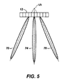
図2乃至4では、送信ビーム70、74、76は全て、探触子アレイの表面上の共通の点から出てくることが分かる。しかし、仮想頂点撮像を図5に示すように利用することができる。この実施例では、同時に、違ったふうに向きが操作されるビーム70、74及び76は、探触子アレイ12の表面上の別の点から出てきている。この例では、3つのビーム70、74及び76は全て、走査パターンの仮想頂点としてよく表される、アレイ探触子の表面の後ろにある、共通の交点VAを有する。仮想頂点走査パターンは効果的には、画像の遠方領域内でも近接領域内でも空間的に分離されるので近接場のクラッタを削減するものである。本発明の範囲内に収まる別の走査パターンは、探触子アレイの表面上の2つ以上の別々の点から発出するが、共通の仮想頂点を必ずしも有するものでないビームを送信するというものである。例えば、図5の3つのビームを、向きが操作される線形アレイのビーム方向と同様に、平行の方向で送信し得る。ビームは全て、同じ角度で左、右に向きを操作し得るものであり、全てを(探触子の表面に対して垂直に)まっすぐの方向に操作し得るものでもある。別の変形は、2つのビームをアレイに対して鋭角の方向に送信し、第3のビ―ムをまっすぐの方向に送信し、第2のビームと第3のビームは、アレイの表面上に、共通の原点を共有する。種々の、異なるステアリング方向の組み合わせが考えられる。
2-4, it can be seen that the transmit
図6は、本発明の原理によって構成される超音波診断撮像システムの構成図を示す。アレイ探触子12を備える走査ヘッド10は、破線の矩形及び平行四辺形によって表す画像フィールドにわたって種々の角度でビームを送信する。3つの走査線視線方向群は、図にはA、B及びCを付して示し、各群は、走査ヘッドに対して別の角度(視線方向)に誘導される。ビームの送信を、アレイ探触子の素子の各々の駆動の位相及び時間を制御するマルチライン送信ビーム形成器14によって制御して、各ビームを所定の原点からアレイに沿って所定の角度で送信する。本発明の原理によれば、マルチライン送信ビーム形成器は、アレイ探触子12に、アレイ探触子の別々の素子に信号が印加される時間を制御することによって前述の図面で例示するように違ったふうに向きが操作される複数の送信ビームを同時に送信させる。各走査線に沿って戻ってくるエコーは、アレイの素子によって受信され、マルチライン受信ビーム形成器16に結合される。マルチライン受信ビーム形成器は、アレイ素子からのエコーを遅延させて合計して、違ったふうに、ずらしたもの及び/又は誘導したものである、同時に処理される複数の受信走査線の各々に沿って、集束させた、コヒーレントなエコー・サンプル系列を形成する。ビーム形成器16として用いるのに適したマルチライン受信ビーム形成器の例は、内容を本明細書及び特許請求の範囲に援用する、「MULTILINE ULTRASOUND BEAMFORMERS」と題する、Henderson他による、西暦2000年12月22日付出願の米国特許公開公報第09/746,165号明細書に記載されている。マルチライン送信ビーム形成器14及びマルチライン受信ビーム形成器16は、システム・コントローラ18の制御下で動作し、システム・コントローラ18は、同様に、超音波システムのユーザによって操作されるユーザ・インタフェース20上の制御部の設定に応答する。システム・コントローラは、各送受信間隔中の所望のビーム数、所望のビーム角度、原点、送信のエネルギ及び周波数を送信するようマルチライン送信ビーム形成器14を制御する。これらの送信特性は、所望の空間的コンパウンドの度合い(別々の視線方向の数)や、送信メカニカル・インデックス(MI)設定などのユーザ設定からシステム・コントローラによって判定し得る。システム・コントローラは、マルチライン受信ビーム形成器16を制御して、用いられるビーム数、開口部及び焦点深度について受信エコー信号を合成するものでもある。
FIG. 6 shows a block diagram of an ultrasonic diagnostic imaging system constructed according to the principle of the present invention. A
走査線エコー信号は、関心の周波数帯を規定する、プログラム可能なディジタル・フィルタ22によってフィルタリングされる。ハーモニック・コントラスト剤の撮像又は、ティッシュ(組織)ハーモニック撮像を行う場合、フィルタ22の通過域は、送信帯域の高調波を通過させるよう設定される。フィルタリングされた信号は更に、検出器24によって検出される。フィルタ及び検出器は一般的に、受信信号を複数の通過域に分離し、個々に検出し、再合成して、周波数コンパウンドによって画像スペックルを削減し得るように複数のフィルタ及び検出器を備える。Bモード撮像の場合、検出器24は、エコー信号エンベロープの振幅検出を行うことになる。ドップラー撮像の場合、エコーの集団を、画像内の点毎に集約し、ドップラー・シフト又はドップラーパワー強度を推定するようドップラー処理する。
The scan line echo signal is filtered by a programmable
本発明の原理によれば、ディジタル信号は、空間的コンパウンドによってプロセッサ30内で処理される。ディジタル・エコー信号は当初、プリプロセッサ32によって前処理される。プリプロセッサ32は、所望される場合、信号サンプルを重み付け係数によって予め重み付けすることができる。サンプルは、特定のコンパウンド画像を形成するのに用いるコンポーネント・フレームの数の関数である重み付け係数によって予め重み付けすることができる。プリプロセッサは、Jago他による米国特許第6,224,552号明細書に更に全面的に記載されているように、1つの重なる画像のエッジにあるエッジラインも重み付けして、コンパウンドが行われるサンプル又は画像の数が変わる遷移部を平滑化することができる。前処理された信号サンプルは更に、リサンプラ34においてレサンプリングを受け得る。リサンプラ34は、Schmiesing他による米国特許第6,135,956号明細書に更に全面的に記載されているように、1つのコンポーネント・フレームの推定を表示空間の画素と空間的に再アラインさせることができる。
In accordance with the principles of the present invention, the digital signal is processed within
リサンプリング後、画像フレームは、合成器36によってコンパウンドされる。合成は、合計、平均化、ピーク検出や他の線形又は非線形の合成手段を備え得る。合成されるサンプルは、当該処理のこの工程における合成の前に、重み付けされ得るものでもある。適切な合成器は、Jagoによる米国特許第6,547,732号明細書に記載されている。最後に、後処理が、ポストプロセッサ38によって行われる。ポストプロセッサは、合成値を、表示値範囲に正規化する。後処理は、ルックアップテーブルによって最も容易に実施することができ、コンパウンド値範囲の、コンパウンド画像の表示に適した値範囲への圧縮及びマッピングを同時に行うことができる。
After resampling, the image frame is compounded by the
コンパウンド処理は、獲得データ空間内又は表示画素空間内で行い得る。一実施形態では、走査変換は、コンパウンド処理に引き続いて、走査変換器40によって行われる。コンパウンド画像は、推定形式又は表示画素形式でシネループ(登録商標)・メモリ42内に記憶し得る。推定形式で記憶される場合、画像を、表示するよう、シネループ・メモリから再生される際に走査変換し得る。走査変換器及びシネループ・メモリは、Quistgaardによる米国特許第5,485,842号明細書、Quistgaardによる米国特許第5,860,924号明細書及びFraser他による米国特許第6,471,652号明細書に記載されているように、空間的コンパウンド画像の3次元表示をレンダリングするのに用い得るものでもある。走査変換後、空間的コンパウンド画像は、表示するようビデオ・プロセッサ44によって処理され、画像ディスプレイ50上に表示される。
Compound processing may be performed in acquired data space or display pixel space. In one embodiment, the scan conversion is performed by the
空間的コンパウンドの更なる詳細は、内容を本明細書及び特許請求の範囲に援用する、Schmiesing他による上記米国特許第6,135,956号明細書で見つけ得る。 Further details of the spatial compound can be found in the above-mentioned US Pat. No. 6,135,956 by Schmiesing et al., The contents of which are incorporated herein by reference.
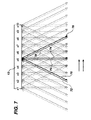
本発明による、空間的コンパウンドの2次元画像フィールドの走査の例を図7に示す。この図面は、視線方向が3つの空間的コンパウンドの10個の送受信間隔の順番列(Tx1乃至Tx10)を示す。送受信間隔Tx5のビームを図中で強調して示している。各受信ビーム軸は、その相当する送信ビームの軸とアラインされているが、例証の目的で、送信ビームと受信ビームは図中ではわずかにずれている。各送受信間隔中に、70、74及び76などの3つの送信ビームが、3つの別々の方向に、すなわち1つが左方向に、1つが右方向に、1つが、(探触子アレイ12の表面に対して垂直に)まっすぐの方向に、同時に送信される。この図は、画像フィールドには、左視線方向に誘導される一走査線群と、右視線方向に誘導される別の走査線群と、垂直視線方向に誘導される第3の走査線群が発射しているということを示している。走査線に沿って出てくるエコーは、空間的に合成される、すなわち、3つの視線方向全てからの発射を受ける画像フィールドの中心にある画像点のコンパウンドを3つの視線方向全てからの信号によって行って最大画像品質の画像領域(「RMIQ」、Robinson他による米国特許第6,210,328号参照。)を生成することになる。RMIQの両側にある画像領域は、2つの視線方向からの信号の合成によってコンパウンドされることになり、画像フィールドの最側端部上にある画像領域は、探触子開口部の端部にある位置によってコンパウンドされないことになる。 An example of a spatial compound 2D image field scan according to the present invention is shown in FIG. This drawing shows an order sequence (Tx1 to Tx10) of 10 transmission / reception intervals whose line-of-sight directions are three spatial compounds. The beam of the transmission / reception interval Tx5 is highlighted in the figure. Each receive beam axis is aligned with its corresponding transmit beam axis, but for illustrative purposes, the transmit and receive beams are slightly offset in the figure. During each transmit / receive interval, three transmit beams, such as 70, 74 and 76, are transmitted in three separate directions: one in the left direction, one in the right direction and one (the surface of the probe array 12). Transmitted simultaneously in a straight direction (perpendicular to). This figure shows that in the image field, there is one scanning line group guided in the left visual line direction, another scanning line group guided in the right visual line direction, and a third scanning line group guided in the vertical visual line direction. Indicates that it is firing. Echoes emerging along the scan line are spatially synthesized, i.e. the compound of the image point in the center of the image field that is fired from all three line-of-sight directions by the signal from all three line-of-sight directions To produce an image area of maximum image quality (see “RMIQ”, US Pat. No. 6,210,328 by Robinson et al.). The image areas on both sides of the RMIQ will be compounded by the synthesis of signals from the two line-of-sight directions, and the image area on the outermost edge of the image field is at the end of the probe opening. It will not be compounded by position.
いくつかのタイプの送信ビーム形成器を用いて複数の同時送信ビームを送信することができ、こうしたタイプのうちの1つを図8に構成図形式で示す。この図面は、3つのビームの波頭100を3つの方向A、B及びCに送信するよう駆動される探触子アレイの素子12.1乃至12.nを示す。図面に示す5つのアレイ素子は、各々の探触子素子の右に示すディジタル伝送ビーム形成器の5つのチャネルによって備えられる信号によって励起される。各送信ビーム形成器チャネルは、所望の送信波形106のディジタル・サンプルを備えるシフト・レジスタ又はメモリ104.1乃至104.nを備える。ディジタル波形は、所望の方向にアレイのビームを誘導するのに必要な各々の時間で、シフト・レジスタからクロックアウトされるか、メモリからアドレス指定されることになるようにシフト・レジスタに配置されるかメモリ内でアドレス指定される。例えば、メモリ/シフト・レジスタ104.1及び104.nでは、2つの送信波形がメモリ/シフト・レジスタの出力の近くにあり、遅延している第3のものがメモリ/シフト・レジスタの右端にある。メモリ/シフト・レジスタ104.2及び104.4では、3つの波形がメモリ/シフト・レジスタの中央付近にあり、メモリ/シフト・レジスタ104.3では、2つの波形が中央にあり、第3のものがメモリ/シフト・レジスタの右側にある。ディジタル波形は、メモリ/シフト・レジスタからアドレス指定又はクロックアウトされ、ディジタル・アナログ変換器102によってアナログ波形に変換され、増幅され、各々の探触子素子に印加される。個々の波形は、探触子アレイの左にある画像フィールド内の個々の素子信号によって形成されるビームが、A方向、B方向及びC方向に誘導されることになる。
Several types of transmit beamformers can be used to transmit multiple simultaneous transmit beams, one of which is shown in block diagram form in FIG. This figure shows the elements 12.1 to 12.12 of the probe array driven to transmit a
3ビーム送信ビーム形成器の別の実施形態は、図9に示す。この実施例では、単一の波形106が送信ビーム形成器のチャネルの全てに印加される。送信ビーム形成器の各チャネルは、3つの遅延を波形に印加させて3つのビームに対する3つの波形を形成する。波形は、アナログ波形生成器であっても、上記ディジタル・メモリ/シフト・レジスタであってもよい装置104によって生成される。装置104がディジタル装置である場合、ディジタル・アナログ変換器102を装置104の出力で用い得る。あるいは、ディジタル遅延部をビーム形成器チャネルにおいて用いてよく、ディジタル・アナログ変換を、遅延の後に行ってもよい。最上部ビーム形成器チャネルは、3つのビームが方向A、B及びCに誘導されることに探触子素子12.1が寄与することが適切である3つの遅延線112、114及び116を有することが分かる。同様に、遅延線112’、114’及び116’は、方向A、B及びCにビームを素子12.2が誘導するのに必要な駆動信号を印加波形が生成するうえでの遅延を備える。他のアレイ素子の遅延は、同様に備えられる。チャネル毎の波形信号は、増幅されるかアナログ信号に変換され、送信ビーム形成器の段110によって増幅される。
Another embodiment of a three beam transmit beamformer is shown in FIG. In this embodiment, a
図8及び9の波頭100が示すように、アレイ探触子によって生成されるビームは、時間的に重なり得るものであり、事実上同時にアレイから送信され得る。このことは、一ビームの送信電圧を探触子素子に、第2のビームの送信電圧と同時に印加することができ、第3のビームの送信電圧とも同時に印加することができるということを意味する。素子に印加される駆動電圧はよって、3つの波形全ての合計であり得る。しかし、診断超音波システムは、患者が安全であるような最大送信音圧レベルを有するよう調節される。更に、最大出力電圧は、送信回路の電源レールによって制限される。3つの波形全ての和が、送信器の調節レベル又は駆動能力を超える場合、探触子の出力を、最大許容可能レベル又は最大可能レベルに制限しなければならない。このことによって、ビームの有効範囲が制限されることになり、よって、診断画像を生成することができる深度が制限されることになる。こうした課題を解決するうえでの1つの方法は、印加可能な電圧レベル又は送信音圧レベルを、合成しても超えない、より長く、振幅がより低い、符号化された送信パルスを用いることによるものである。このジレンマに対する別の解決策は、図10に示し、図10では、3つの送信ビームが、同じ送受信間隔中に、重ならない時間間隔で生成される。ビームは、2つのビームの駆動信号がアレイ探触子に同時に印加される時間が何ら存在しないように、重ならない時間間隔で送信される。よって、各ビームを、最大撮像深度を可能にする、最大調節電力で生成することができる。図10の実施例では、このことは、波形106が素子に重ならないように備えられるようにする、より長い遅延104によって実現される。この実施形態の欠点は、より長い合計遅延が、図10の遅延線104がより長いことによって示されるように必要である。更に、より高度な受信ビーム形成器が、送信するうえでの時間的な差異を追跡し、補償するのに必要である。遅延線がより長いことに対する必要性は一般的に、超音波システムの構成部分のサイズ若しくは面積又は費用の増加を強いる。
As illustrated by the
こうした欠点を軽減するために、図11に示すように、バルク遅延部120を、個々のビーム遅延部の前に用い得る。この実施例では、波形生成器104によって印加される送信波形106は、バルク遅延部120の右端から進み、右から左にクロッキング又はアドレス指定される。送信波形106が、バルク遅延部の第1のタップT1に達する、(事実上直ぐであり得る)場合、波形を、アナログ形式に変換し、かつ/又は、所望の場合に段102’によって増幅し、チャネル遅延部118の遅延部aに印加し、段102によって、増幅し、かつ/又は、アナログ形式への変換を行い、探触子アレイの素子に印加して、第1の送信ビームを生成し、第1のビ―ムは、第1の方向、この例では方向Cに誘導される。タップT1からの送信波形がチャネル遅延部118によって遅延される一方、送信波形106は、バルク遅延部120のタップT2に進む。波形106を更に、後の時点でタップT2によってチャネル遅延部118のb遅延部に印加して、第1のビームCと時間的に重ならない第2の方向(この例ではA)に誘導されるビームを生成することになる。波形106は、バルク遅延部を進み、バルク遅延部120のタップT3から更に後の時点で発出する。この信号を、チャネル遅延部118のc遅延部によって遅延させ、探触子素子に印加して第3の重ならないビームBを形成する。送信ビームは時間的に重ならないように生成されるので、各ビームを、より深い深度の撮像を行うよう、最大許容可能な音響強度で生成することができる。
To alleviate these drawbacks, a
別の実施例では、信号生成器104を、ビーム毎に1度、送受信間隔毎に3つの別個の回、作動させ得るものであり、かわりに、遅延線120が1:3逆多重化装置になり得る。更に別の実施例では、同じ信号生成器をビーム毎に作動させ得るものであり、遅延素子を時間多重で、各送信によって変え得る。
In another embodiment, the
クラッタは、同じ順番列での、図10及び図11の実施例による、ほぼ同時のビームの反復的な送信から生じ得る。このクラッタを削減するために、複数ビームの送信の順番列を、所定のパターンにおいてか、順序を変えることによって、フレーム単位又は送信間隔単位で変え得る。 Clutter can result from repeated transmission of approximately simultaneous beams according to the embodiment of FIGS. 10 and 11 in the same permutation. In order to reduce this clutter, the sequence of transmissions of multiple beams can be changed in frame units or transmission interval units in a predetermined pattern or by changing the order.
探触子アレイ上の共通の点から同時ビームが発出する上記実施例に伴う、クラッタの問題が最も大きい状態は、ビームの仮想的なオーバラップが発生する近接場において生じる。こうした問題は、符号化信号を復号化する適切な受信処理によってよりよく各々の受信ビームを区別することができるように、同時ビームの各々について違ったふうに符号化される波形を送信することによって解決し得る。公知の直交符号は、符号化励起として場合によっては表す処理である、別々の送信ビームの波頭の送信波を符号化するのに用いることができる。 The largest clutter problem associated with the above embodiment, where simultaneous beams are emitted from a common point on the probe array, occurs in the near field where the virtual overlap of the beams occurs. These problems are caused by transmitting differently encoded waveforms for each of the simultaneous beams so that each received beam can be better distinguished by an appropriate reception process that decodes the encoded signal. It can be solved. Known orthogonal codes can be used to encode transmit waves at the front of separate transmit beams, a process sometimes represented as encoded excitation.
クラッタを削減するうえでの別の手法は、近接画像領域及び遠方画像領域に別々の送信ゾーンを用いるというものである。遠方領域の場合、同時に、違ったふうに向きが操作される複数ビームを上記のように用いる。近接領域では、従来の単一ラインの送信及び受信を用い、それによって、近接領域におけるマルチライン送信クラッタが全くなくなる。この単一ラインの送信及び受信に必要な更なる時間は大きくないが、それは、最も不愉快なクラッタが生じる近傍画像領域が、通常、1センチメートル程度で、比較的浅いからである。この時間は、遠くのゾーンからの信号が減衰するよりも速く減衰するこの近接ゾーン
に、より高い周波数を用い、よって、送受信間隔間のデッド時間を最小にすることによって最小にすることができる。表示される画像は、この実施例では、両方のゾーンからのエコー信号を空間的にコンパウンドし、用いて、単一の画像フレームを形成する場合、マルチライン撮像と単一ライン撮像との合成になる。
Another approach to reducing clutter is to use separate transmission zones for the near and far image regions. In the case of a far field, a plurality of beams whose directions are manipulated differently are used as described above. The proximity region uses conventional single line transmission and reception, thereby eliminating any multi-line transmission clutter in the proximity region. The additional time required to transmit and receive this single line is not great, because the neighborhood image region where the most unpleasant clutter occurs is usually on the order of 1 centimeter and is relatively shallow. This time can be minimized by using higher frequencies in this close zone that decays faster than signals from distant zones decay, thus minimizing dead time between transmit and receive intervals. The displayed image, in this embodiment, is a composite of multi-line and single-line imaging when echo signals from both zones are spatially compounded and used to form a single image frame. Become.
Claims (19)
アレイ探触子と、
該アレイ探触子に結合され、単一の送受信間隔中に別々の方向に複数のビームを前記アレイ探触子に送信させるよう動作するマルチライン送信ビーム形成器と、
前記アレイ探触子に結合され、前記単一の送受信間隔中に受信されるエコーに応じて前記別々の方向で受信ビームのエコー信号を形成するよう動作するマルチライン受信ビーム形成器と、
前記エコー信号に応じ、別々の方向から受信された画像フィールドにおける共通の点に関する信号を合成するよう動作する合成器と、
該合成器に結合され、空間コンパウンド画像を表示するディスプレイとを備えることを特徴とする超音波診断撮像システム。 An ultrasound diagnostic imaging system for generating a spatial compound image comprising:
With an array probe,
A multi-line transmit beamformer coupled to the array probe and operative to cause the array probe to transmit multiple beams in different directions during a single transmit / receive interval;
A multi-line receive beamformer coupled to the array probe and operative to form echo signals of the receive beam in the different directions in response to echoes received during the single transmit / receive interval;
In response to the echo signal, a synthesizer operable to synthesize signals relating to a common point in the image field received from different directions;
An ultrasonic diagnostic imaging system comprising: a display coupled to the synthesizer for displaying a spatial compound image.
前記マルチライン送信ビーム形成器は、各々が前記アレイ探触子の、かかる素子に結合される複数のビーム形成器チャネルを備え、
各チャネルは、前記複数のビームの、複数の送信信号の遅延線を備えることを特徴とする超音波診断撮像システム。 The ultrasonic diagnostic imaging system of claim 1,
The multi-line transmit beamformer comprises a plurality of beamformer channels each coupled to such elements of the array probe;
Each channel includes a plurality of transmission signal delay lines of the plurality of beams.
前記遅延線が、前記複数の送信信号を直列に遅延させるよう動作する直列遅延線を備えることを特徴とする超音波診断撮像システム。 The ultrasonic diagnostic imaging system according to claim 2,
The ultrasonic diagnostic imaging system, wherein the delay line includes a serial delay line that operates to delay the plurality of transmission signals in series.
前記遅延線が、前記複数の送信信号の、複数の並列遅延線素子を備えることを特徴とする超音波診断撮像システム。 The ultrasonic diagnostic imaging system according to claim 2,
The ultrasonic diagnostic imaging system, wherein the delay line includes a plurality of parallel delay line elements of the plurality of transmission signals.
前記遅延線が、アドレス指定可能メモリを備えることを特徴とする超音波診断撮像システム。 The ultrasonic diagnostic imaging system according to claim 2,
The ultrasonic diagnostic imaging system, wherein the delay line includes an addressable memory.
前記遅延線がディジタル遅延線であり、各チャネルが更に、探触子素子に結合されるディジタル・アナログ変換器を備えることを特徴とする超音波診断撮像システム。 The ultrasonic diagnostic imaging system according to claim 2,
The ultrasonic diagnostic imaging system, wherein the delay line is a digital delay line, and each channel further includes a digital-to-analog converter coupled to a probe element.
前記マルチライン送信ビーム形成器が、単一の送信間隔中に別々の方向に複数の直交符号化ビームを前記アレイ探触子に送信させるよう更に動作することを特徴とする超音波診断撮像システム。 The ultrasonic diagnostic imaging system of claim 1,
The ultrasound diagnostic imaging system, wherein the multi-line transmit beamformer is further operative to cause the array probe to transmit a plurality of orthogonally encoded beams in different directions during a single transmission interval.
前記マルチライン送信ビーム形成器は更に、単一の送信間隔中に別々の方向に複数ビームを前記アレイ探触子に送信させるか、単一の送信間隔中に単一ビームを前記アレイ探触子に送信させるよう動作し、
前記マルチライン受信ビーム形成器は、単一の送受信間隔中に深度が高い場所からの前記別々の方向での複数の受信ビームのエコー信号を形成し、単一の送受信間隔中に深度が低い場所からの単一の受信ビームのエコー信号を形成するよう動作することを特徴とする超音波診断撮像システム。 The ultrasonic diagnostic imaging system of claim 1,
The multi-line transmit beamformer further causes the array probe to transmit multiple beams in different directions during a single transmission interval or a single beam during the single transmission interval. To send to
The multi-line receive beamformer forms echo signals of a plurality of receive beams in the different directions from a high depth location during a single transmit / receive interval, and a low depth location during a single transmit / receive interval. An ultrasound diagnostic imaging system, characterized in that it operates to form an echo signal of a single received beam from the.
単一の送受信間隔中に別々の方向に複数の超音波ビームを送信する工程と、
前記複数のビームに応じて、前記単一の送受信間隔中に前記別々の方向からエコー信号を受信する工程と、
別々のビーム方向から受信される信号を空間的に合成する工程と、
空間コンパウンド超音波画像を表示する工程とを備えることを特徴とする方法。 A method of forming a spatial compound ultrasound image comprising:
Transmitting a plurality of ultrasonic beams in different directions during a single transmission and reception interval;
In response to the plurality of beams, receiving echo signals from the different directions during the single transmission and reception interval;
Spatially combining signals received from different beam directions;
Displaying a spatial compound ultrasound image.
送信する工程が更に、
探触子アレイの表面上の共通の点から複数の超音波ビームを送信する工程を備えることを特徴とする方法。 The method of claim 9, comprising:
The process of sending further
Transmitting a plurality of ultrasonic beams from a common point on the surface of the probe array.
送信する工程が更に、
探触子アレイの表面上の別々の点から発出する複数の超音波ビームを送信する工程を備えることを特徴とする方法。 The method of claim 9, comprising:
The process of sending further
Transmitting a plurality of ultrasonic beams emanating from different points on the surface of the probe array.
受信する工程が更に、
特定の方向に送信されたビームに応じて空間的に別個の複数のビームを受信する工程を更に備えることを特徴とする方法。 The method of claim 9, comprising:
The step of receiving further
Receiving a plurality of spatially distinct beams in response to beams transmitted in a particular direction.
送信する工程が更に、
単一の送受信間隔中に前記複数のビームの前記送信を時間的に分離する工程を備えることを特徴とする方法。 The method of claim 9, comprising:
The process of sending further
A method comprising temporally separating the transmissions of the plurality of beams during a single transmit / receive interval.
時間的に分離する工程が、複数ビームからの電圧が探触子素子に同時に、過剰に印加されないようにすることを特徴とする方法。 14. The method of claim 13, wherein
The method of temporally isolating prevents the voltage from multiple beams from being applied excessively to the probe element simultaneously.
時間的に分離する工程が、診断限度を超える、複数ビームからの音圧が生じないようにする工程を備えることを特徴とする方法。 14. The method of claim 13, wherein
A method characterized in that the temporal separation step comprises preventing sound pressure from multiple beams from exceeding a diagnostic limit.
送信する工程が、単一の送受信間隔中に単一の超音波ビームを代替的に送信する工程を更に備え、
受信する工程が、前記複数のビームに応じて深度の高い場所から、別々のビーム方向からのエコー信号を第1の送受信間隔中に受信し、単一のビームの前記送信に応じて深度の低い場所から、第2の送受信間隔中に単一のビーム方向からのエコー信号を受信する工程を更に備えることを特徴とする方法。 The method of claim 9, comprising:
Transmitting further comprises alternatively transmitting a single ultrasound beam during a single transmit and receive interval;
The receiving step receives echo signals from different beam directions during a first transmission / reception interval from a location with a high depth according to the plurality of beams, and a low depth according to the transmission of a single beam. Receiving a echo signal from a single beam direction from a location during a second transmit / receive interval.
送信する工程が、ビームのメインローブが別の方向のビームの少なくとも1つのサイドローブと同心でないように別々の方向に複数の超音波ビームを送信する工程を更に備えることを特徴とする方法。 The method of claim 9, comprising:
The method of transmitting further comprising transmitting a plurality of ultrasonic beams in different directions such that the main lobe of the beam is not concentric with at least one side lobe of the beam in another direction.
送信する工程が、一方向のビームの前記メインローブと、別の方向のビームの前記サイドロ―ブとが重ならないようにするよう開口部又アポダイゼーションの関数を合わせる工程を更に備えることを特徴とする方法。 The method of claim 17, comprising:
The step of transmitting further comprises the step of matching the aperture or apodization function so that the main lobe of the beam in one direction and the side lobe of the beam in another direction do not overlap. Method.
受信する工程が、前記送信ビームの各々と同軸である受信ビームを受信する工程を更に備えることを特徴とする方法。 The method of claim 9, comprising:
The method of receiving further comprises receiving a receive beam that is coaxial with each of the transmit beams.
Applications Claiming Priority (2)
| Application Number | Priority Date | Filing Date | Title |
|---|---|---|---|
| US50179503P | 2003-09-10 | 2003-09-10 | |
| PCT/IB2004/051415 WO2005024462A1 (en) | 2003-09-10 | 2004-08-06 | Ultrasonic spatial compounding with multiple simultaneous beam transmission |
Publications (2)
| Publication Number | Publication Date |
|---|---|
| JP2007504876A true JP2007504876A (en) | 2007-03-08 |
| JP4584927B2 JP4584927B2 (en) | 2010-11-24 |
Family
ID=34273069
Family Applications (1)
| Application Number | Title | Priority Date | Filing Date |
|---|---|---|---|
| JP2006525929A Active JP4584927B2 (en) | 2003-09-10 | 2004-08-06 | Spatial ultrasound compound with simultaneous transmission of multiple beams |
Country Status (7)
| Country | Link |
|---|---|
| US (1) | US7537567B2 (en) |
| EP (1) | EP1664840B1 (en) |
| JP (1) | JP4584927B2 (en) |
| CN (1) | CN100559213C (en) |
| AT (1) | ATE410704T1 (en) |
| DE (1) | DE602004017028D1 (en) |
| WO (1) | WO2005024462A1 (en) |
Cited By (8)
| Publication number | Priority date | Publication date | Assignee | Title |
|---|---|---|---|---|
| JP2005177494A (en) * | 2003-12-19 | 2005-07-07 | General Electric Co <Ge> | Method and apparatus for flow parameter imaging |
| JP2012066078A (en) * | 2010-09-21 | 2012-04-05 | Toshiba Corp | Ultrasound probe and ultrasound imaging system |
| JP2012187206A (en) * | 2011-03-09 | 2012-10-04 | Fujifilm Corp | Ultrasound diagnostic apparatus |
| JP2012187205A (en) * | 2011-03-09 | 2012-10-04 | Fujifilm Corp | Ultrasound diagnostic apparatus |
| JP2012187187A (en) * | 2011-03-09 | 2012-10-04 | Fujifilm Corp | Ultrasound diagnostic apparatus |
| WO2014021105A1 (en) * | 2012-07-30 | 2014-02-06 | 日立アロカメディカル株式会社 | Ultrasonic diagnostic device |
| JP2016514530A (en) * | 2013-03-25 | 2016-05-23 | コーニンクレッカ フィリップス エヌ ヴェKoninklijke Philips N.V. | Ultrasound diagnostic imaging system. |
| WO2019176232A1 (en) * | 2018-03-16 | 2019-09-19 | 株式会社日立製作所 | Ultrasonic diagnostic device and transmission control method |
Families Citing this family (35)
| Publication number | Priority date | Publication date | Assignee | Title |
|---|---|---|---|---|
| US7335160B2 (en) * | 2003-11-06 | 2008-02-26 | Fujifilm Corporation | Ultrasonic transmitting and receiving apparatus |
| US7632229B2 (en) * | 2004-08-09 | 2009-12-15 | General Electric Company | Range dependent weighting for spatial compound imaging |
| US20100150412A1 (en) * | 2005-03-28 | 2010-06-17 | Koninklijke Philips Electronics, N.V. | Adaptive parallel artifact mitigation |
| US20060241454A1 (en) * | 2005-04-05 | 2006-10-26 | Siemens Medical Solutions Usa, Inc. | Transmit multibeam for compounding ultrasound data |
| JP4860945B2 (en) * | 2005-06-09 | 2012-01-25 | 日立アロカメディカル株式会社 | Ultrasonic diagnostic equipment |
| CN101442938B (en) * | 2006-05-12 | 2014-02-19 | 皇家飞利浦电子股份有限公司 | Ultrasonic synthetic transmit focusing with a multiline beamformer |
| EP2019600B1 (en) * | 2006-05-12 | 2015-09-16 | Koninklijke Philips Electronics, N.V. | Retrospective dynamic transmit focusing for spatial compounding |
| JP2009542286A (en) * | 2006-06-27 | 2009-12-03 | コーニンクレッカ フィリップス エレクトロニクス エヌ ヴィ | Ultrasound imaging system and method using multiline acquisition at high frame rate |
| KR100954988B1 (en) * | 2006-09-26 | 2010-04-29 | 주식회사 메디슨 | Ultrasound system and method for forming ultrasound image |
| US7984651B2 (en) * | 2006-11-10 | 2011-07-26 | Penrith Corporation | Transducer array imaging system |
| US8600299B2 (en) * | 2006-11-10 | 2013-12-03 | Siemens Medical Solutions Usa, Inc. | Transducer array imaging system |
| US9295444B2 (en) | 2006-11-10 | 2016-03-29 | Siemens Medical Solutions Usa, Inc. | Transducer array imaging system |
| CN101199430B (en) | 2006-12-15 | 2011-12-28 | 深圳迈瑞生物医疗电子股份有限公司 | Spatial compound imaging method and equipment and ultrasonic imaging system thereof |
| US20080287799A1 (en) * | 2007-05-16 | 2008-11-20 | General Electric Company | Method and apparatus for measuring volumetric flow |
| CN101449983B (en) * | 2007-11-29 | 2014-12-10 | 深圳迈瑞生物医疗电子股份有限公司 | Scanning changing interpolation method and device of ultrasonic linear-array deflexion imaging |
| US9117439B2 (en) * | 2008-03-13 | 2015-08-25 | Supersonic Imagine | Method and apparatus for ultrasound synthetic imagining |
| KR101121267B1 (en) * | 2009-09-02 | 2012-03-23 | 삼성메디슨 주식회사 | Ultrasound system and method for providing compound image considering steering angle |
| US20110245676A1 (en) * | 2010-03-31 | 2011-10-06 | General Electronic Company | Method and apparatus for ultrasound signal acquisition and processing |
| US8582865B2 (en) * | 2010-04-28 | 2013-11-12 | General Electric Company | Ultrasound imaging with ray casting and software-based image reconstruction |
| BR112012029607A2 (en) | 2010-05-26 | 2016-08-09 | Koninkl Philips Electronics Nv | 3d ultrasound diagnostic imaging system for cardiac display with high 3d frame rate |
| JP5965898B2 (en) | 2010-05-26 | 2016-08-10 | コーニンクレッカ フィリップス エヌ ヴェKoninklijke Philips N.V. | High volume rate 3D ultrasound imaging |
| US20130258805A1 (en) * | 2010-10-11 | 2013-10-03 | B-K Medical Aps | Methods and systems for producing compounded ultrasound images |
| KR101183017B1 (en) | 2010-10-19 | 2012-09-18 | 삼성메디슨 주식회사 | Ultrasound system and method for providing ultrasound spatial compound image based on center line |
| JP6295267B2 (en) | 2012-12-03 | 2018-03-14 | コーニンクレッカ フィリップス エヌ ヴェKoninklijke Philips N.V. | Ultrasonic transducer probe with microbeamformer for multi-line imaging |
| CN103545612B (en) * | 2013-10-28 | 2015-09-09 | 北京理工大学 | A kind of satellite beams center method of estimation for communication in moving system |
| JP6799537B2 (en) | 2014-12-09 | 2020-12-16 | コーニンクレッカ フィリップス エヌ ヴェKoninklijke Philips N.V. | Single modality-based visual identification of medical intervention devices from the organization |
| US9784874B2 (en) | 2014-12-11 | 2017-10-10 | Baker Hughes Incorporated | Multi-beam phased array acoustic transducer operation for downhole applications |
| EP3307174B1 (en) | 2015-06-11 | 2019-04-03 | Koninklijke Philips N.V. | Ultrasonic transducer array probe for shear wave imaging |
| US10779800B2 (en) * | 2016-12-01 | 2020-09-22 | B-K Medical Aps | Ultrasound imaging transducer electrical noise compensation |
| CN110913769A (en) * | 2017-07-09 | 2020-03-24 | 利兰斯坦福初级大学董事会 | Ultrasound imaging with speckle reduction using spectral synthesis |
| DE102018200324A1 (en) * | 2018-01-11 | 2019-07-11 | Robert Bosch Gmbh | Ultrasonic sensor and fluid tank with ultrasonic sensor |
| US11690595B2 (en) | 2018-04-09 | 2023-07-04 | BFLY Operations, Inc | Methods and apparatuses for offloading ultrasound data |
| EP3677907A1 (en) | 2019-01-04 | 2020-07-08 | Xarion Laser Acoustics GmbH | Device and method for testing a test object |
| CN113905671A (en) * | 2019-05-30 | 2022-01-07 | 皇家飞利浦有限公司 | Coded synchronized medical intervention image signal and sensor signal |
| CN110327077B (en) * | 2019-07-09 | 2022-04-15 | 深圳开立生物医疗科技股份有限公司 | Blood flow display method and device, ultrasonic equipment and storage medium |
Citations (7)
| Publication number | Priority date | Publication date | Assignee | Title |
|---|---|---|---|---|
| JPH0838473A (en) * | 1994-07-29 | 1996-02-13 | Hitachi Medical Corp | Ultrasonic diagnostic device |
| JPH10507936A (en) * | 1994-08-05 | 1998-08-04 | アキュソン コーポレイション | Method and apparatus for a transmit beam generator system |
| JPH11221217A (en) * | 1998-02-10 | 1999-08-17 | Toshiba Corp | Ultrasonograph |
| JPH11318892A (en) * | 1998-05-08 | 1999-11-24 | Ge Yokogawa Medical Systems Ltd | Ultrasonography and ultrasonograph |
| JP2000157548A (en) * | 1998-11-23 | 2000-06-13 | General Electric Co <Ge> | Method and system for imaging ultrasonic wave scattered body |
| JP2001187054A (en) * | 1999-10-12 | 2001-07-10 | General Electric Co <Ge> | Numerical optimization of ultrasound beam path |
| JP2002526224A (en) * | 1998-10-01 | 2002-08-20 | コーニンクレッカ フィリップス エレクトロニクス エヌ ヴィ | Ultrasound diagnostic imaging system with variable space synthesis |
Family Cites Families (27)
| Publication number | Priority date | Publication date | Assignee | Title |
|---|---|---|---|---|
| US4159462A (en) * | 1977-08-18 | 1979-06-26 | General Electric Company | Ultrasonic multi-sector scanner |
| US4561019A (en) * | 1983-05-16 | 1985-12-24 | Riverside Research Institute | Frequency diversity for image enhancement |
| US4596145A (en) * | 1983-09-20 | 1986-06-24 | Smith Stephen W | Acoustic orthoscopic imaging system |
| US4644795A (en) * | 1985-07-29 | 1987-02-24 | Advanced Technology Laboratories, Inc. | High resolution multiline ultrasonic beamformer |
| US5148810A (en) * | 1990-02-12 | 1992-09-22 | Acuson Corporation | Variable origin-variable angle acoustic scanning method and apparatus |
| US5318033A (en) * | 1992-04-17 | 1994-06-07 | Hewlett-Packard Company | Method and apparatus for increasing the frame rate and resolution of a phased array imaging system |
| US5469851A (en) * | 1994-08-09 | 1995-11-28 | Hewlett-Packard Company | Time multiplexed digital ultrasound beamformer |
| US5485842A (en) * | 1994-11-30 | 1996-01-23 | Advanced Technology Laboratories, Inc. | Ultrasonic diagnostic scan conversion for three dimensional display processing |
| AU1983397A (en) * | 1996-02-29 | 1997-09-16 | Acuson Corporation | Multiple ultrasound image registration system, method and transducer |
| US5860924A (en) * | 1996-11-26 | 1999-01-19 | Advanced Technology Laboratories, Inc. | Three dimensional ultrasonic diagnostic image rendering from tissue and flow images |
| US6193663B1 (en) * | 1997-12-18 | 2001-02-27 | Acuson Corporation | Diagnostic ultrasound imaging method and system with improved frame rate |
| US6074348A (en) * | 1998-03-31 | 2000-06-13 | General Electric Company | Method and apparatus for enhanced flow imaging in B-mode ultrasound |
| US6224552B1 (en) * | 1998-10-01 | 2001-05-01 | Atl Ultrasound | Ultrasonic diagnostic imaging system with reduced spatial compounding seam artifacts |
| US6126598A (en) * | 1998-10-01 | 2000-10-03 | Atl Ultrasound, Inc. | Ultrasonic diagnostic imaging system with adaptive spatial compounding |
| US6135956A (en) * | 1998-10-01 | 2000-10-24 | Atl Ultrasound, Inc. | Ultrasonic diagnostic imaging system with spatial compounding of resampled image data |
| US6547732B2 (en) * | 1998-10-01 | 2003-04-15 | Koninklijke Philips Electronics N.V. | Adaptive image processing for spatial compounding |
| US6179780B1 (en) * | 1999-08-06 | 2001-01-30 | Acuson Corporation | Method and apparatus for medical diagnostic ultrasound real-time 3-D transmitting and imaging |
| JP3662821B2 (en) * | 2000-07-26 | 2005-06-22 | 理想科学工業株式会社 | Paper feeding device and printing device using the same |
| US6468216B1 (en) * | 2000-08-24 | 2002-10-22 | Kininklijke Philips Electronics N.V. | Ultrasonic diagnostic imaging of the coronary arteries |
| US6440075B1 (en) * | 2000-10-02 | 2002-08-27 | Koninklijke Philips Electronics N.V. | Ultrasonic diagnostic imaging of nonlinearly intermodulated and harmonic frequency components |
| US6695783B2 (en) * | 2000-12-22 | 2004-02-24 | Koninklijke Philips Electronics N.V. | Multiline ultrasound beamformers |
| JP2002257803A (en) * | 2001-02-28 | 2002-09-11 | Fuji Photo Film Co Ltd | Method and apparatus for imaging ultrasonic wave |
| KR100393370B1 (en) * | 2001-04-25 | 2003-07-31 | 주식회사 메디슨 | Ultrasound imaging method and apparatus using orthogonal golay codes |
| US6527723B2 (en) * | 2001-06-26 | 2003-03-04 | Koninklijke Philips Electronics N.V. | Variable multi-dimensional apodization control for ultrasonic transducers |
| US6676603B2 (en) * | 2001-11-09 | 2004-01-13 | Kretztechnik Ag | Method and apparatus for beam compounding |
| US6730033B2 (en) * | 2002-05-16 | 2004-05-04 | Siemens Medical Systems, Inc. | Two dimensional array and methods for imaging in three dimensions |
| US6585648B1 (en) * | 2002-11-15 | 2003-07-01 | Koninklijke Philips Electronics N.V. | System, method and machine readable program for performing ultrasonic fat beam transmission and multiline receive imaging |
-
2004
- 2004-08-06 DE DE602004017028T patent/DE602004017028D1/en active Active
- 2004-08-06 AT AT04744757T patent/ATE410704T1/en not_active IP Right Cessation
- 2004-08-06 EP EP04744757A patent/EP1664840B1/en active Active
- 2004-08-06 JP JP2006525929A patent/JP4584927B2/en active Active
- 2004-08-06 CN CNB200480025861XA patent/CN100559213C/en active Active
- 2004-08-06 WO PCT/IB2004/051415 patent/WO2005024462A1/en active Application Filing
- 2004-08-06 US US10/570,193 patent/US7537567B2/en active Active
Patent Citations (7)
| Publication number | Priority date | Publication date | Assignee | Title |
|---|---|---|---|---|
| JPH0838473A (en) * | 1994-07-29 | 1996-02-13 | Hitachi Medical Corp | Ultrasonic diagnostic device |
| JPH10507936A (en) * | 1994-08-05 | 1998-08-04 | アキュソン コーポレイション | Method and apparatus for a transmit beam generator system |
| JPH11221217A (en) * | 1998-02-10 | 1999-08-17 | Toshiba Corp | Ultrasonograph |
| JPH11318892A (en) * | 1998-05-08 | 1999-11-24 | Ge Yokogawa Medical Systems Ltd | Ultrasonography and ultrasonograph |
| JP2002526224A (en) * | 1998-10-01 | 2002-08-20 | コーニンクレッカ フィリップス エレクトロニクス エヌ ヴィ | Ultrasound diagnostic imaging system with variable space synthesis |
| JP2000157548A (en) * | 1998-11-23 | 2000-06-13 | General Electric Co <Ge> | Method and system for imaging ultrasonic wave scattered body |
| JP2001187054A (en) * | 1999-10-12 | 2001-07-10 | General Electric Co <Ge> | Numerical optimization of ultrasound beam path |
Cited By (11)
| Publication number | Priority date | Publication date | Assignee | Title |
|---|---|---|---|---|
| JP2005177494A (en) * | 2003-12-19 | 2005-07-07 | General Electric Co <Ge> | Method and apparatus for flow parameter imaging |
| JP2012139569A (en) * | 2003-12-19 | 2012-07-26 | General Electric Co <Ge> | Method and apparatus for flow parameter imaging |
| JP2012066078A (en) * | 2010-09-21 | 2012-04-05 | Toshiba Corp | Ultrasound probe and ultrasound imaging system |
| JP2012187206A (en) * | 2011-03-09 | 2012-10-04 | Fujifilm Corp | Ultrasound diagnostic apparatus |
| JP2012187205A (en) * | 2011-03-09 | 2012-10-04 | Fujifilm Corp | Ultrasound diagnostic apparatus |
| JP2012187187A (en) * | 2011-03-09 | 2012-10-04 | Fujifilm Corp | Ultrasound diagnostic apparatus |
| WO2014021105A1 (en) * | 2012-07-30 | 2014-02-06 | 日立アロカメディカル株式会社 | Ultrasonic diagnostic device |
| JP2016514530A (en) * | 2013-03-25 | 2016-05-23 | コーニンクレッカ フィリップス エヌ ヴェKoninklijke Philips N.V. | Ultrasound diagnostic imaging system. |
| WO2019176232A1 (en) * | 2018-03-16 | 2019-09-19 | 株式会社日立製作所 | Ultrasonic diagnostic device and transmission control method |
| JP2019154977A (en) * | 2018-03-16 | 2019-09-19 | 株式会社日立製作所 | Ultrasonic diagnostic apparatus |
| JP7008549B2 (en) | 2018-03-16 | 2022-01-25 | 富士フイルムヘルスケア株式会社 | Ultrasound diagnostic device |
Also Published As
| Publication number | Publication date |
|---|---|
| JP4584927B2 (en) | 2010-11-24 |
| DE602004017028D1 (en) | 2008-11-20 |
| WO2005024462A1 (en) | 2005-03-17 |
| CN1849529A (en) | 2006-10-18 |
| US20060293596A1 (en) | 2006-12-28 |
| EP1664840B1 (en) | 2008-10-08 |
| EP1664840A1 (en) | 2006-06-07 |
| ATE410704T1 (en) | 2008-10-15 |
| US7537567B2 (en) | 2009-05-26 |
| CN100559213C (en) | 2009-11-11 |
Similar Documents
| Publication | Publication Date | Title |
|---|---|---|
| JP4584927B2 (en) | Spatial ultrasound compound with simultaneous transmission of multiple beams | |
| JP4828651B2 (en) | Ultrasound diagnostic imaging system with variable spatial synthesis | |
| EP1563318B1 (en) | Method and apparatus for automatically setting the transmit aperture and apodization of an ultrasound transducer array | |
| US7540842B2 (en) | Diagnostic ultrasound imaging method and system with improved frame rate | |
| US6159153A (en) | Methods and systems for ultrasound scanning using spatially and spectrally separated transmit ultrasound beams | |
| JP5281727B2 (en) | Method and apparatus for improving sidelobe performance of sparse arrays using harmonic imaging | |
| US6123670A (en) | Ultrasound imaging with optimal image quality in region of interest | |
| JP5324733B2 (en) | Ultrasonic spatial synthesis using a curved array scan head | |
| US6544177B1 (en) | Ultrasonic diagnostic imaging system and method with harmonic spatial compounding | |
| US6911008B2 (en) | Compound ultrasound imaging method | |
| US6733453B2 (en) | Elevation compounding for ultrasound imaging | |
| KR101120675B1 (en) | Method of Compounding an Ultrasound Image Using a Spatial Compounding | |
| US20070083109A1 (en) | Adaptive line synthesis for ultrasound | |
| EP1697765B1 (en) | Ultrasonic diagnostic contrast imaging with spatial compounding | |
| KR101120691B1 (en) | Method of Compounding an Ultrasound Image Using a Spatial Compounding | |
| US11607194B2 (en) | Ultrasound imaging system with depth-dependent transmit focus | |
| WO2005034758A1 (en) | Ultrasonographic device |
Legal Events
| Date | Code | Title | Description |
|---|---|---|---|
| A621 | Written request for application examination |
Free format text: JAPANESE INTERMEDIATE CODE: A621 Effective date: 20070803 |
|
| A977 | Report on retrieval |
Free format text: JAPANESE INTERMEDIATE CODE: A971007 Effective date: 20100721 |
|
| TRDD | Decision of grant or rejection written | ||
| A01 | Written decision to grant a patent or to grant a registration (utility model) |
Free format text: JAPANESE INTERMEDIATE CODE: A01 Effective date: 20100810 |
|
| A01 | Written decision to grant a patent or to grant a registration (utility model) |
Free format text: JAPANESE INTERMEDIATE CODE: A01 |
|
| A61 | First payment of annual fees (during grant procedure) |
Free format text: JAPANESE INTERMEDIATE CODE: A61 Effective date: 20100902 |
|
| R150 | Certificate of patent or registration of utility model |
Ref document number: 4584927 Country of ref document: JP Free format text: JAPANESE INTERMEDIATE CODE: R150 Free format text: JAPANESE INTERMEDIATE CODE: R150 |
|
| FPAY | Renewal fee payment (event date is renewal date of database) |
Free format text: PAYMENT UNTIL: 20130910 Year of fee payment: 3 |
|
| R250 | Receipt of annual fees |
Free format text: JAPANESE INTERMEDIATE CODE: R250 |
|
| R250 | Receipt of annual fees |
Free format text: JAPANESE INTERMEDIATE CODE: R250 |
|
| R250 | Receipt of annual fees |
Free format text: JAPANESE INTERMEDIATE CODE: R250 |
|
| R250 | Receipt of annual fees |
Free format text: JAPANESE INTERMEDIATE CODE: R250 |
|
| R250 | Receipt of annual fees |
Free format text: JAPANESE INTERMEDIATE CODE: R250 |
|
| R250 | Receipt of annual fees |
Free format text: JAPANESE INTERMEDIATE CODE: R250 |
|
| R250 | Receipt of annual fees |
Free format text: JAPANESE INTERMEDIATE CODE: R250 |
|
| R250 | Receipt of annual fees |
Free format text: JAPANESE INTERMEDIATE CODE: R250 |
|
| R250 | Receipt of annual fees |
Free format text: JAPANESE INTERMEDIATE CODE: R250 |
|
| R250 | Receipt of annual fees |
Free format text: JAPANESE INTERMEDIATE CODE: R250 |
|
| R250 | Receipt of annual fees |
Free format text: JAPANESE INTERMEDIATE CODE: R250 |