JP2007504635A - Fast start fuel reforming system and technology - Google Patents
Fast start fuel reforming system and technology Download PDFInfo
- Publication number
- JP2007504635A JP2007504635A JP2006533140A JP2006533140A JP2007504635A JP 2007504635 A JP2007504635 A JP 2007504635A JP 2006533140 A JP2006533140 A JP 2006533140A JP 2006533140 A JP2006533140 A JP 2006533140A JP 2007504635 A JP2007504635 A JP 2007504635A
- Authority
- JP
- Japan
- Prior art keywords
- reformer
- heating
- vaporizer
- fuel
- steam
- Prior art date
- Legal status (The legal status is an assumption and is not a legal conclusion. Google has not performed a legal analysis and makes no representation as to the accuracy of the status listed.)
- Pending
Links
Images


Classifications
-
- B—PERFORMING OPERATIONS; TRANSPORTING
- B01—PHYSICAL OR CHEMICAL PROCESSES OR APPARATUS IN GENERAL
- B01J—CHEMICAL OR PHYSICAL PROCESSES, e.g. CATALYSIS OR COLLOID CHEMISTRY; THEIR RELEVANT APPARATUS
- B01J19/00—Chemical, physical or physico-chemical processes in general; Their relevant apparatus
- B01J19/0093—Microreactors, e.g. miniaturised or microfabricated reactors
-
- H—ELECTRICITY
- H01—ELECTRIC ELEMENTS
- H01M—PROCESSES OR MEANS, e.g. BATTERIES, FOR THE DIRECT CONVERSION OF CHEMICAL ENERGY INTO ELECTRICAL ENERGY
- H01M8/00—Fuel cells; Manufacture thereof
- H01M8/06—Combination of fuel cells with means for production of reactants or for treatment of residues
-
- B—PERFORMING OPERATIONS; TRANSPORTING
- B01—PHYSICAL OR CHEMICAL PROCESSES OR APPARATUS IN GENERAL
- B01F—MIXING, e.g. DISSOLVING, EMULSIFYING OR DISPERSING
- B01F25/00—Flow mixers; Mixers for falling materials, e.g. solid particles
- B01F25/40—Static mixers
- B01F25/42—Static mixers in which the mixing is affected by moving the components jointly in changing directions, e.g. in tubes provided with baffles or obstructions
- B01F25/421—Static mixers in which the mixing is affected by moving the components jointly in changing directions, e.g. in tubes provided with baffles or obstructions by moving the components in a convoluted or labyrinthine path
- B01F25/422—Static mixers in which the mixing is affected by moving the components jointly in changing directions, e.g. in tubes provided with baffles or obstructions by moving the components in a convoluted or labyrinthine path between stacked plates, e.g. grooved or perforated plates
-
- B—PERFORMING OPERATIONS; TRANSPORTING
- B01—PHYSICAL OR CHEMICAL PROCESSES OR APPARATUS IN GENERAL
- B01F—MIXING, e.g. DISSOLVING, EMULSIFYING OR DISPERSING
- B01F33/00—Other mixers; Mixing plants; Combinations of mixers
- B01F33/30—Micromixers
-
- B—PERFORMING OPERATIONS; TRANSPORTING
- B01—PHYSICAL OR CHEMICAL PROCESSES OR APPARATUS IN GENERAL
- B01J—CHEMICAL OR PHYSICAL PROCESSES, e.g. CATALYSIS OR COLLOID CHEMISTRY; THEIR RELEVANT APPARATUS
- B01J19/00—Chemical, physical or physico-chemical processes in general; Their relevant apparatus
- B01J19/0006—Controlling or regulating processes
- B01J19/0013—Controlling the temperature of the process
-
- B—PERFORMING OPERATIONS; TRANSPORTING
- B01—PHYSICAL OR CHEMICAL PROCESSES OR APPARATUS IN GENERAL
- B01J—CHEMICAL OR PHYSICAL PROCESSES, e.g. CATALYSIS OR COLLOID CHEMISTRY; THEIR RELEVANT APPARATUS
- B01J19/00—Chemical, physical or physico-chemical processes in general; Their relevant apparatus
- B01J19/24—Stationary reactors without moving elements inside
- B01J19/248—Reactors comprising multiple separated flow channels
- B01J19/249—Plate-type reactors
-
- B—PERFORMING OPERATIONS; TRANSPORTING
- B01—PHYSICAL OR CHEMICAL PROCESSES OR APPARATUS IN GENERAL
- B01J—CHEMICAL OR PHYSICAL PROCESSES, e.g. CATALYSIS OR COLLOID CHEMISTRY; THEIR RELEVANT APPARATUS
- B01J8/00—Chemical or physical processes in general, conducted in the presence of fluids and solid particles; Apparatus for such processes
- B01J8/02—Chemical or physical processes in general, conducted in the presence of fluids and solid particles; Apparatus for such processes with stationary particles, e.g. in fixed beds
- B01J8/04—Chemical or physical processes in general, conducted in the presence of fluids and solid particles; Apparatus for such processes with stationary particles, e.g. in fixed beds the fluid passing successively through two or more beds
- B01J8/0403—Chemical or physical processes in general, conducted in the presence of fluids and solid particles; Apparatus for such processes with stationary particles, e.g. in fixed beds the fluid passing successively through two or more beds the fluid flow within the beds being predominantly horizontal
- B01J8/0407—Chemical or physical processes in general, conducted in the presence of fluids and solid particles; Apparatus for such processes with stationary particles, e.g. in fixed beds the fluid passing successively through two or more beds the fluid flow within the beds being predominantly horizontal through two or more cylindrical annular shaped beds
- B01J8/0415—Chemical or physical processes in general, conducted in the presence of fluids and solid particles; Apparatus for such processes with stationary particles, e.g. in fixed beds the fluid passing successively through two or more beds the fluid flow within the beds being predominantly horizontal through two or more cylindrical annular shaped beds the beds being superimposed one above the other
-
- C—CHEMISTRY; METALLURGY
- C01—INORGANIC CHEMISTRY
- C01B—NON-METALLIC ELEMENTS; COMPOUNDS THEREOF; METALLOIDS OR COMPOUNDS THEREOF NOT COVERED BY SUBCLASS C01C
- C01B3/00—Hydrogen; Gaseous mixtures containing hydrogen; Separation of hydrogen from mixtures containing it; Purification of hydrogen; Reversible storage of hydrogen
- C01B3/02—Production of hydrogen; Production of gaseous mixtures containing hydrogen
- C01B3/32—Production of hydrogen; Production of gaseous mixtures containing hydrogen by reaction of gaseous or liquid organic compounds with gasifying agents, e.g. water, carbon dioxide or air
- C01B3/34—Production of hydrogen; Production of gaseous mixtures containing hydrogen by reaction of gaseous or liquid organic compounds with gasifying agents, e.g. water, carbon dioxide or air by reaction of hydrocarbons with gasifying agents
- C01B3/38—Production of hydrogen; Production of gaseous mixtures containing hydrogen by reaction of gaseous or liquid organic compounds with gasifying agents, e.g. water, carbon dioxide or air by reaction of hydrocarbons with gasifying agents using catalysts
- C01B3/384—Production of hydrogen; Production of gaseous mixtures containing hydrogen by reaction of gaseous or liquid organic compounds with gasifying agents, e.g. water, carbon dioxide or air by reaction of hydrocarbons with gasifying agents using catalysts with external heating of the catalyst
-
- C—CHEMISTRY; METALLURGY
- C01—INORGANIC CHEMISTRY
- C01B—NON-METALLIC ELEMENTS; COMPOUNDS THEREOF; METALLOIDS OR COMPOUNDS THEREOF NOT COVERED BY SUBCLASS C01C
- C01B3/00—Hydrogen; Gaseous mixtures containing hydrogen; Separation of hydrogen from mixtures containing it; Purification of hydrogen; Reversible storage of hydrogen
- C01B3/02—Production of hydrogen; Production of gaseous mixtures containing hydrogen
- C01B3/32—Production of hydrogen; Production of gaseous mixtures containing hydrogen by reaction of gaseous or liquid organic compounds with gasifying agents, e.g. water, carbon dioxide or air
- C01B3/34—Production of hydrogen; Production of gaseous mixtures containing hydrogen by reaction of gaseous or liquid organic compounds with gasifying agents, e.g. water, carbon dioxide or air by reaction of hydrocarbons with gasifying agents
- C01B3/48—Production of hydrogen; Production of gaseous mixtures containing hydrogen by reaction of gaseous or liquid organic compounds with gasifying agents, e.g. water, carbon dioxide or air by reaction of hydrocarbons with gasifying agents followed by reaction of water vapour with carbon monoxide
-
- H—ELECTRICITY
- H01—ELECTRIC ELEMENTS
- H01M—PROCESSES OR MEANS, e.g. BATTERIES, FOR THE DIRECT CONVERSION OF CHEMICAL ENERGY INTO ELECTRICAL ENERGY
- H01M8/00—Fuel cells; Manufacture thereof
- H01M8/04—Auxiliary arrangements, e.g. for control of pressure or for circulation of fluids
-
- H—ELECTRICITY
- H01—ELECTRIC ELEMENTS
- H01M—PROCESSES OR MEANS, e.g. BATTERIES, FOR THE DIRECT CONVERSION OF CHEMICAL ENERGY INTO ELECTRICAL ENERGY
- H01M8/00—Fuel cells; Manufacture thereof
- H01M8/04—Auxiliary arrangements, e.g. for control of pressure or for circulation of fluids
- H01M8/04007—Auxiliary arrangements, e.g. for control of pressure or for circulation of fluids related to heat exchange
- H01M8/04014—Heat exchange using gaseous fluids; Heat exchange by combustion of reactants
-
- H—ELECTRICITY
- H01—ELECTRIC ELEMENTS
- H01M—PROCESSES OR MEANS, e.g. BATTERIES, FOR THE DIRECT CONVERSION OF CHEMICAL ENERGY INTO ELECTRICAL ENERGY
- H01M8/00—Fuel cells; Manufacture thereof
- H01M8/06—Combination of fuel cells with means for production of reactants or for treatment of residues
- H01M8/0606—Combination of fuel cells with means for production of reactants or for treatment of residues with means for production of gaseous reactants
- H01M8/0612—Combination of fuel cells with means for production of reactants or for treatment of residues with means for production of gaseous reactants from carbon-containing material
- H01M8/0618—Reforming processes, e.g. autothermal, partial oxidation or steam reforming
-
- B—PERFORMING OPERATIONS; TRANSPORTING
- B01—PHYSICAL OR CHEMICAL PROCESSES OR APPARATUS IN GENERAL
- B01F—MIXING, e.g. DISSOLVING, EMULSIFYING OR DISPERSING
- B01F2101/00—Mixing characterised by the nature of the mixed materials or by the application field
- B01F2101/59—Mixing reaction ingredients for fuel cells
-
- B—PERFORMING OPERATIONS; TRANSPORTING
- B01—PHYSICAL OR CHEMICAL PROCESSES OR APPARATUS IN GENERAL
- B01J—CHEMICAL OR PHYSICAL PROCESSES, e.g. CATALYSIS OR COLLOID CHEMISTRY; THEIR RELEVANT APPARATUS
- B01J2208/00—Processes carried out in the presence of solid particles; Reactors therefor
- B01J2208/00008—Controlling the process
- B01J2208/00628—Controlling the composition of the reactive mixture
- B01J2208/00646—Means for starting up the reaction
-
- B—PERFORMING OPERATIONS; TRANSPORTING
- B01—PHYSICAL OR CHEMICAL PROCESSES OR APPARATUS IN GENERAL
- B01J—CHEMICAL OR PHYSICAL PROCESSES, e.g. CATALYSIS OR COLLOID CHEMISTRY; THEIR RELEVANT APPARATUS
- B01J2208/00—Processes carried out in the presence of solid particles; Reactors therefor
- B01J2208/00008—Controlling the process
- B01J2208/00716—Means for reactor start-up
-
- B—PERFORMING OPERATIONS; TRANSPORTING
- B01—PHYSICAL OR CHEMICAL PROCESSES OR APPARATUS IN GENERAL
- B01J—CHEMICAL OR PHYSICAL PROCESSES, e.g. CATALYSIS OR COLLOID CHEMISTRY; THEIR RELEVANT APPARATUS
- B01J2219/00—Chemical, physical or physico-chemical processes in general; Their relevant apparatus
- B01J2219/00781—Aspects relating to microreactors
- B01J2219/00783—Laminate assemblies, i.e. the reactor comprising a stack of plates
-
- B—PERFORMING OPERATIONS; TRANSPORTING
- B01—PHYSICAL OR CHEMICAL PROCESSES OR APPARATUS IN GENERAL
- B01J—CHEMICAL OR PHYSICAL PROCESSES, e.g. CATALYSIS OR COLLOID CHEMISTRY; THEIR RELEVANT APPARATUS
- B01J2219/00—Chemical, physical or physico-chemical processes in general; Their relevant apparatus
- B01J2219/00781—Aspects relating to microreactors
- B01J2219/00801—Means to assemble
- B01J2219/00804—Plurality of plates
-
- B—PERFORMING OPERATIONS; TRANSPORTING
- B01—PHYSICAL OR CHEMICAL PROCESSES OR APPARATUS IN GENERAL
- B01J—CHEMICAL OR PHYSICAL PROCESSES, e.g. CATALYSIS OR COLLOID CHEMISTRY; THEIR RELEVANT APPARATUS
- B01J2219/00—Chemical, physical or physico-chemical processes in general; Their relevant apparatus
- B01J2219/00781—Aspects relating to microreactors
- B01J2219/00801—Means to assemble
- B01J2219/0081—Plurality of modules
-
- B—PERFORMING OPERATIONS; TRANSPORTING
- B01—PHYSICAL OR CHEMICAL PROCESSES OR APPARATUS IN GENERAL
- B01J—CHEMICAL OR PHYSICAL PROCESSES, e.g. CATALYSIS OR COLLOID CHEMISTRY; THEIR RELEVANT APPARATUS
- B01J2219/00—Chemical, physical or physico-chemical processes in general; Their relevant apparatus
- B01J2219/00781—Aspects relating to microreactors
- B01J2219/00819—Materials of construction
- B01J2219/00822—Metal
-
- B—PERFORMING OPERATIONS; TRANSPORTING
- B01—PHYSICAL OR CHEMICAL PROCESSES OR APPARATUS IN GENERAL
- B01J—CHEMICAL OR PHYSICAL PROCESSES, e.g. CATALYSIS OR COLLOID CHEMISTRY; THEIR RELEVANT APPARATUS
- B01J2219/00—Chemical, physical or physico-chemical processes in general; Their relevant apparatus
- B01J2219/00781—Aspects relating to microreactors
- B01J2219/00819—Materials of construction
- B01J2219/00835—Comprising catalytically active material
-
- B—PERFORMING OPERATIONS; TRANSPORTING
- B01—PHYSICAL OR CHEMICAL PROCESSES OR APPARATUS IN GENERAL
- B01J—CHEMICAL OR PHYSICAL PROCESSES, e.g. CATALYSIS OR COLLOID CHEMISTRY; THEIR RELEVANT APPARATUS
- B01J2219/00—Chemical, physical or physico-chemical processes in general; Their relevant apparatus
- B01J2219/00781—Aspects relating to microreactors
- B01J2219/00851—Additional features
- B01J2219/00858—Aspects relating to the size of the reactor
- B01J2219/0086—Dimensions of the flow channels
-
- B—PERFORMING OPERATIONS; TRANSPORTING
- B01—PHYSICAL OR CHEMICAL PROCESSES OR APPARATUS IN GENERAL
- B01J—CHEMICAL OR PHYSICAL PROCESSES, e.g. CATALYSIS OR COLLOID CHEMISTRY; THEIR RELEVANT APPARATUS
- B01J2219/00—Chemical, physical or physico-chemical processes in general; Their relevant apparatus
- B01J2219/00781—Aspects relating to microreactors
- B01J2219/00851—Additional features
- B01J2219/00858—Aspects relating to the size of the reactor
- B01J2219/00862—Dimensions of the reaction cavity itself
-
- B—PERFORMING OPERATIONS; TRANSPORTING
- B01—PHYSICAL OR CHEMICAL PROCESSES OR APPARATUS IN GENERAL
- B01J—CHEMICAL OR PHYSICAL PROCESSES, e.g. CATALYSIS OR COLLOID CHEMISTRY; THEIR RELEVANT APPARATUS
- B01J2219/00—Chemical, physical or physico-chemical processes in general; Their relevant apparatus
- B01J2219/00781—Aspects relating to microreactors
- B01J2219/00851—Additional features
- B01J2219/00867—Microreactors placed in series, on the same or on different supports
-
- B—PERFORMING OPERATIONS; TRANSPORTING
- B01—PHYSICAL OR CHEMICAL PROCESSES OR APPARATUS IN GENERAL
- B01J—CHEMICAL OR PHYSICAL PROCESSES, e.g. CATALYSIS OR COLLOID CHEMISTRY; THEIR RELEVANT APPARATUS
- B01J2219/00—Chemical, physical or physico-chemical processes in general; Their relevant apparatus
- B01J2219/00781—Aspects relating to microreactors
- B01J2219/00851—Additional features
- B01J2219/00869—Microreactors placed in parallel, on the same or on different supports
-
- B—PERFORMING OPERATIONS; TRANSPORTING
- B01—PHYSICAL OR CHEMICAL PROCESSES OR APPARATUS IN GENERAL
- B01J—CHEMICAL OR PHYSICAL PROCESSES, e.g. CATALYSIS OR COLLOID CHEMISTRY; THEIR RELEVANT APPARATUS
- B01J2219/00—Chemical, physical or physico-chemical processes in general; Their relevant apparatus
- B01J2219/00781—Aspects relating to microreactors
- B01J2219/00873—Heat exchange
-
- B—PERFORMING OPERATIONS; TRANSPORTING
- B01—PHYSICAL OR CHEMICAL PROCESSES OR APPARATUS IN GENERAL
- B01J—CHEMICAL OR PHYSICAL PROCESSES, e.g. CATALYSIS OR COLLOID CHEMISTRY; THEIR RELEVANT APPARATUS
- B01J2219/00—Chemical, physical or physico-chemical processes in general; Their relevant apparatus
- B01J2219/00781—Aspects relating to microreactors
- B01J2219/00891—Feeding or evacuation
-
- B—PERFORMING OPERATIONS; TRANSPORTING
- B01—PHYSICAL OR CHEMICAL PROCESSES OR APPARATUS IN GENERAL
- B01J—CHEMICAL OR PHYSICAL PROCESSES, e.g. CATALYSIS OR COLLOID CHEMISTRY; THEIR RELEVANT APPARATUS
- B01J2219/00—Chemical, physical or physico-chemical processes in general; Their relevant apparatus
- B01J2219/00781—Aspects relating to microreactors
- B01J2219/0095—Control aspects
- B01J2219/00952—Sensing operations
- B01J2219/00954—Measured properties
- B01J2219/00961—Temperature
-
- B—PERFORMING OPERATIONS; TRANSPORTING
- B01—PHYSICAL OR CHEMICAL PROCESSES OR APPARATUS IN GENERAL
- B01J—CHEMICAL OR PHYSICAL PROCESSES, e.g. CATALYSIS OR COLLOID CHEMISTRY; THEIR RELEVANT APPARATUS
- B01J2219/00—Chemical, physical or physico-chemical processes in general; Their relevant apparatus
- B01J2219/00781—Aspects relating to microreactors
- B01J2219/0095—Control aspects
- B01J2219/00986—Microprocessor
-
- C—CHEMISTRY; METALLURGY
- C01—INORGANIC CHEMISTRY
- C01B—NON-METALLIC ELEMENTS; COMPOUNDS THEREOF; METALLOIDS OR COMPOUNDS THEREOF NOT COVERED BY SUBCLASS C01C
- C01B2203/00—Integrated processes for the production of hydrogen or synthesis gas
- C01B2203/02—Processes for making hydrogen or synthesis gas
- C01B2203/0205—Processes for making hydrogen or synthesis gas containing a reforming step
- C01B2203/0227—Processes for making hydrogen or synthesis gas containing a reforming step containing a catalytic reforming step
- C01B2203/0233—Processes for making hydrogen or synthesis gas containing a reforming step containing a catalytic reforming step the reforming step being a steam reforming step
-
- C—CHEMISTRY; METALLURGY
- C01—INORGANIC CHEMISTRY
- C01B—NON-METALLIC ELEMENTS; COMPOUNDS THEREOF; METALLOIDS OR COMPOUNDS THEREOF NOT COVERED BY SUBCLASS C01C
- C01B2203/00—Integrated processes for the production of hydrogen or synthesis gas
- C01B2203/02—Processes for making hydrogen or synthesis gas
- C01B2203/0283—Processes for making hydrogen or synthesis gas containing a CO-shift step, i.e. a water gas shift step
-
- C—CHEMISTRY; METALLURGY
- C01—INORGANIC CHEMISTRY
- C01B—NON-METALLIC ELEMENTS; COMPOUNDS THEREOF; METALLOIDS OR COMPOUNDS THEREOF NOT COVERED BY SUBCLASS C01C
- C01B2203/00—Integrated processes for the production of hydrogen or synthesis gas
- C01B2203/04—Integrated processes for the production of hydrogen or synthesis gas containing a purification step for the hydrogen or the synthesis gas
- C01B2203/0405—Purification by membrane separation
-
- C—CHEMISTRY; METALLURGY
- C01—INORGANIC CHEMISTRY
- C01B—NON-METALLIC ELEMENTS; COMPOUNDS THEREOF; METALLOIDS OR COMPOUNDS THEREOF NOT COVERED BY SUBCLASS C01C
- C01B2203/00—Integrated processes for the production of hydrogen or synthesis gas
- C01B2203/04—Integrated processes for the production of hydrogen or synthesis gas containing a purification step for the hydrogen or the synthesis gas
- C01B2203/0435—Catalytic purification
- C01B2203/044—Selective oxidation of carbon monoxide
-
- C—CHEMISTRY; METALLURGY
- C01—INORGANIC CHEMISTRY
- C01B—NON-METALLIC ELEMENTS; COMPOUNDS THEREOF; METALLOIDS OR COMPOUNDS THEREOF NOT COVERED BY SUBCLASS C01C
- C01B2203/00—Integrated processes for the production of hydrogen or synthesis gas
- C01B2203/04—Integrated processes for the production of hydrogen or synthesis gas containing a purification step for the hydrogen or the synthesis gas
- C01B2203/0465—Composition of the impurity
- C01B2203/047—Composition of the impurity the impurity being carbon monoxide
-
- C—CHEMISTRY; METALLURGY
- C01—INORGANIC CHEMISTRY
- C01B—NON-METALLIC ELEMENTS; COMPOUNDS THEREOF; METALLOIDS OR COMPOUNDS THEREOF NOT COVERED BY SUBCLASS C01C
- C01B2203/00—Integrated processes for the production of hydrogen or synthesis gas
- C01B2203/06—Integration with other chemical processes
- C01B2203/066—Integration with other chemical processes with fuel cells
-
- C—CHEMISTRY; METALLURGY
- C01—INORGANIC CHEMISTRY
- C01B—NON-METALLIC ELEMENTS; COMPOUNDS THEREOF; METALLOIDS OR COMPOUNDS THEREOF NOT COVERED BY SUBCLASS C01C
- C01B2203/00—Integrated processes for the production of hydrogen or synthesis gas
- C01B2203/08—Methods of heating or cooling
- C01B2203/0805—Methods of heating the process for making hydrogen or synthesis gas
- C01B2203/0811—Methods of heating the process for making hydrogen or synthesis gas by combustion of fuel
- C01B2203/0822—Methods of heating the process for making hydrogen or synthesis gas by combustion of fuel the fuel containing hydrogen
-
- C—CHEMISTRY; METALLURGY
- C01—INORGANIC CHEMISTRY
- C01B—NON-METALLIC ELEMENTS; COMPOUNDS THEREOF; METALLOIDS OR COMPOUNDS THEREOF NOT COVERED BY SUBCLASS C01C
- C01B2203/00—Integrated processes for the production of hydrogen or synthesis gas
- C01B2203/08—Methods of heating or cooling
- C01B2203/0805—Methods of heating the process for making hydrogen or synthesis gas
- C01B2203/0811—Methods of heating the process for making hydrogen or synthesis gas by combustion of fuel
- C01B2203/0827—Methods of heating the process for making hydrogen or synthesis gas by combustion of fuel at least part of the fuel being a recycle stream
-
- C—CHEMISTRY; METALLURGY
- C01—INORGANIC CHEMISTRY
- C01B—NON-METALLIC ELEMENTS; COMPOUNDS THEREOF; METALLOIDS OR COMPOUNDS THEREOF NOT COVERED BY SUBCLASS C01C
- C01B2203/00—Integrated processes for the production of hydrogen or synthesis gas
- C01B2203/08—Methods of heating or cooling
- C01B2203/0805—Methods of heating the process for making hydrogen or synthesis gas
- C01B2203/085—Methods of heating the process for making hydrogen or synthesis gas by electric heating
-
- C—CHEMISTRY; METALLURGY
- C01—INORGANIC CHEMISTRY
- C01B—NON-METALLIC ELEMENTS; COMPOUNDS THEREOF; METALLOIDS OR COMPOUNDS THEREOF NOT COVERED BY SUBCLASS C01C
- C01B2203/00—Integrated processes for the production of hydrogen or synthesis gas
- C01B2203/08—Methods of heating or cooling
- C01B2203/0805—Methods of heating the process for making hydrogen or synthesis gas
- C01B2203/0866—Methods of heating the process for making hydrogen or synthesis gas by combination of different heating methods
-
- C—CHEMISTRY; METALLURGY
- C01—INORGANIC CHEMISTRY
- C01B—NON-METALLIC ELEMENTS; COMPOUNDS THEREOF; METALLOIDS OR COMPOUNDS THEREOF NOT COVERED BY SUBCLASS C01C
- C01B2203/00—Integrated processes for the production of hydrogen or synthesis gas
- C01B2203/08—Methods of heating or cooling
- C01B2203/0872—Methods of cooling
- C01B2203/0888—Methods of cooling by evaporation of a fluid
- C01B2203/0894—Generation of steam
-
- C—CHEMISTRY; METALLURGY
- C01—INORGANIC CHEMISTRY
- C01B—NON-METALLIC ELEMENTS; COMPOUNDS THEREOF; METALLOIDS OR COMPOUNDS THEREOF NOT COVERED BY SUBCLASS C01C
- C01B2203/00—Integrated processes for the production of hydrogen or synthesis gas
- C01B2203/12—Feeding the process for making hydrogen or synthesis gas
- C01B2203/1276—Mixing of different feed components
- C01B2203/1282—Mixing of different feed components using static mixers
-
- C—CHEMISTRY; METALLURGY
- C01—INORGANIC CHEMISTRY
- C01B—NON-METALLIC ELEMENTS; COMPOUNDS THEREOF; METALLOIDS OR COMPOUNDS THEREOF NOT COVERED BY SUBCLASS C01C
- C01B2203/00—Integrated processes for the production of hydrogen or synthesis gas
- C01B2203/12—Feeding the process for making hydrogen or synthesis gas
- C01B2203/1288—Evaporation of one or more of the different feed components
- C01B2203/1294—Evaporation by heat exchange with hot process stream
-
- C—CHEMISTRY; METALLURGY
- C01—INORGANIC CHEMISTRY
- C01B—NON-METALLIC ELEMENTS; COMPOUNDS THEREOF; METALLOIDS OR COMPOUNDS THEREOF NOT COVERED BY SUBCLASS C01C
- C01B2203/00—Integrated processes for the production of hydrogen or synthesis gas
- C01B2203/16—Controlling the process
- C01B2203/1604—Starting up the process
-
- C—CHEMISTRY; METALLURGY
- C01—INORGANIC CHEMISTRY
- C01B—NON-METALLIC ELEMENTS; COMPOUNDS THEREOF; METALLOIDS OR COMPOUNDS THEREOF NOT COVERED BY SUBCLASS C01C
- C01B2203/00—Integrated processes for the production of hydrogen or synthesis gas
- C01B2203/16—Controlling the process
- C01B2203/1695—Adjusting the feed of the combustion
-
- C—CHEMISTRY; METALLURGY
- C01—INORGANIC CHEMISTRY
- C01B—NON-METALLIC ELEMENTS; COMPOUNDS THEREOF; METALLOIDS OR COMPOUNDS THEREOF NOT COVERED BY SUBCLASS C01C
- C01B2203/00—Integrated processes for the production of hydrogen or synthesis gas
- C01B2203/80—Aspect of integrated processes for the production of hydrogen or synthesis gas not covered by groups C01B2203/02 - C01B2203/1695
- C01B2203/82—Several process steps of C01B2203/02 - C01B2203/08 integrated into a single apparatus
-
- H—ELECTRICITY
- H01—ELECTRIC ELEMENTS
- H01M—PROCESSES OR MEANS, e.g. BATTERIES, FOR THE DIRECT CONVERSION OF CHEMICAL ENERGY INTO ELECTRICAL ENERGY
- H01M8/00—Fuel cells; Manufacture thereof
- H01M8/06—Combination of fuel cells with means for production of reactants or for treatment of residues
- H01M8/0662—Treatment of gaseous reactants or gaseous residues, e.g. cleaning
-
- Y—GENERAL TAGGING OF NEW TECHNOLOGICAL DEVELOPMENTS; GENERAL TAGGING OF CROSS-SECTIONAL TECHNOLOGIES SPANNING OVER SEVERAL SECTIONS OF THE IPC; TECHNICAL SUBJECTS COVERED BY FORMER USPC CROSS-REFERENCE ART COLLECTIONS [XRACs] AND DIGESTS
- Y02—TECHNOLOGIES OR APPLICATIONS FOR MITIGATION OR ADAPTATION AGAINST CLIMATE CHANGE
- Y02E—REDUCTION OF GREENHOUSE GAS [GHG] EMISSIONS, RELATED TO ENERGY GENERATION, TRANSMISSION OR DISTRIBUTION
- Y02E60/00—Enabling technologies; Technologies with a potential or indirect contribution to GHG emissions mitigation
- Y02E60/30—Hydrogen technology
- Y02E60/50—Fuel cells
-
- Y—GENERAL TAGGING OF NEW TECHNOLOGICAL DEVELOPMENTS; GENERAL TAGGING OF CROSS-SECTIONAL TECHNOLOGIES SPANNING OVER SEVERAL SECTIONS OF THE IPC; TECHNICAL SUBJECTS COVERED BY FORMER USPC CROSS-REFERENCE ART COLLECTIONS [XRACs] AND DIGESTS
- Y02—TECHNOLOGIES OR APPLICATIONS FOR MITIGATION OR ADAPTATION AGAINST CLIMATE CHANGE
- Y02P—CLIMATE CHANGE MITIGATION TECHNOLOGIES IN THE PRODUCTION OR PROCESSING OF GOODS
- Y02P20/00—Technologies relating to chemical industry
- Y02P20/10—Process efficiency
Landscapes
- Chemical & Material Sciences (AREA)
- Chemical Kinetics & Catalysis (AREA)
- Organic Chemistry (AREA)
- Engineering & Computer Science (AREA)
- Combustion & Propulsion (AREA)
- Manufacturing & Machinery (AREA)
- Sustainable Development (AREA)
- Sustainable Energy (AREA)
- Electrochemistry (AREA)
- General Chemical & Material Sciences (AREA)
- Life Sciences & Earth Sciences (AREA)
- General Health & Medical Sciences (AREA)
- Health & Medical Sciences (AREA)
- Inorganic Chemistry (AREA)
- Physics & Mathematics (AREA)
- Fluid Mechanics (AREA)
- Dispersion Chemistry (AREA)
- Hydrogen, Water And Hydrids (AREA)
- Fuel Cell (AREA)
Abstract
搭載型燃料処理装置は、マイクロチャネル蒸気改質反応器30及び燃焼ガスで連続的に加熱される水気化器40を含む。改質器30及び気化器40は、共に低い燃焼サイド圧力降下を可能とする交流パネル形状である。燃料は蒸気に直接注入され、迅速低温始動時に、燃焼ガス流量及び蒸気対炭素比の双方とも定常状態運転値よりも実質的に増加する。迅速低温始動は管理可能な電力消費量で30秒以内に達成され得るので、自動車燃料電池用途において用いるための障害を除去する。The onboard fuel processor includes a microchannel steam reforming reactor 30 and a water vaporizer 40 that is continuously heated with combustion gases. Both the reformer 30 and the vaporizer 40 have an AC panel shape that enables a low combustion side pressure drop. Fuel is injected directly into the steam, and during rapid cold start, both the combustion gas flow rate and the steam to carbon ratio both increase substantially from the steady state operating value. Rapid cold start can be achieved within 30 seconds with manageable power consumption, thus eliminating obstacles for use in automotive fuel cell applications.
Description
一形態において、本発明は、水素リッチ燃料流を燃料電池に提供するための燃料改質システムに関し、特に迅速に始動可能で且つ効率的運転可能なシステムに関する。 In one aspect, the present invention relates to a fuel reforming system for providing a hydrogen-rich fuel stream to a fuel cell, and more particularly to a system that can be quickly started and operated efficiently.
燃料電池は、燃料及び酸化剤の電気化学反応からエネルギーを産出するデバイスであり、高い効率と比較的害のない副産物ゆえに魅力的なエネルギー代替物であると考えられている。多くの燃料電池はセル用の燃料として水素を用いるように設計されているが、車載用または携帯発電機として、補助電源ユニット(APU)又はバックアップ電源として使用するなどの多くの用途においては、多量の必要な水素ガスの獲得及び/又は貯蔵が現行では実用的ではない。これを解決するために、より容易に入手可能な源又はより容易に貯蔵される源から必要な時に水素を製造するように、システムが開発されつつある。 Fuel cells are devices that produce energy from the electrochemical reaction of fuel and oxidant, and are considered attractive energy substitutes due to their high efficiency and relatively harmless by-products. Many fuel cells are designed to use hydrogen as a fuel for the cell, but in many applications, such as in-vehicle or portable generators, as auxiliary power units (APUs) or as backup power supplies, The acquisition and / or storage of the necessary hydrogen gas is not currently practical. To solve this, systems are being developed to produce hydrogen when needed from more readily available sources or more easily stored sources.
このようなアプローチの一つに、炭化水素燃料を使用可能な水素に処理又は改質することがある。このようなアプローチの利点は、炭化水素燃料が一般に貯蔵しやすく、例えばガソリン、ディーゼル燃料、天然ガスなどの数種の有用な炭化水素類のための多数の分配インフラ(社会基盤)がすでに存在していることである。典型的に用いられている主要な炭化水素改質反応は、水素の適切な收率を達成するために多量の熱及び/又は高められた反応温度を必要とする。これらの高い温度及び/又は熱需要は、始動時のエネルギー消費量及び速度及び燃料電池が製造された水素から有用なエネルギーを発生させ始めることができるまでの時間遅延などのシステム始動に対する取り組みを提示する。 One such approach is to treat or reform the hydrocarbon fuel into usable hydrogen. The advantage of such an approach is that hydrocarbon fuels are generally easy to store and there are already numerous distribution infrastructures (social infrastructure) for several useful hydrocarbons such as gasoline, diesel fuel, natural gas, etc. It is that. The main hydrocarbon reforming reactions that are typically used require large amounts of heat and / or elevated reaction temperatures to achieve adequate yields of hydrogen. These high temperature and / or heat demands present efforts to start the system such as energy consumption and speed at start-up and the time delay before the fuel cell can begin to generate useful energy from the hydrogen produced. To do.
例えば、蒸気改質反応は、典型的には触媒の存在下で、炭化水素類を一酸化炭素及び水素に酸化するために蒸気を使用する。蒸気改質は、強い吸熱反応であり、反応速度を改良し、水素の平衡收率を改良するために典型的には高い温度で行われる。蒸気改質に基づく燃料処理システムは、本発明者により自動車用に開発されている(Progress on the Development of a micro channel steam reformer for Automotive Applications, G. A. Whyatt et at., 2002 AIChE Spring National Meeting参照)。しかし、このシステムは、周囲温度から合理的な蒸気改質速度が達成される650℃付近の運転温度まで始動させるために20分程度を要している。これは商業的実施を妨げ、搭載型燃料処理装置について米国エネルギー省(the U. S. Department Energy)により確立された始動時間目標、2005年までに1分以内及び2010年までに30秒以内に合致しない。したがって、改良が必要であり、本発明は劇的に始動時間を短縮することができる蒸気改質に基づく燃料処理システムである。 For example, steam reforming reactions use steam to oxidize hydrocarbons to carbon monoxide and hydrogen, typically in the presence of a catalyst. Steam reforming is a strongly endothermic reaction and is typically performed at elevated temperatures to improve the reaction rate and improve the equilibrium yield of hydrogen. A fuel treatment system based on steam reforming has been developed for automobiles by the present inventor (see Progress on the Development of a microchannel steam reformer for Automotive Applications, GA A. Whyatt et at., 2002 AIChE Spring National Meeting). However, this system requires about 20 minutes to start from ambient temperature to an operating temperature near 650 ° C. where a reasonable steam reforming rate is achieved. This hinders commercial implementation and does not meet start-up time targets established by the US Department of Energy for on-board fuel processors within 1 minute by 2005 and 30 seconds by 2010. Thus, improvements are needed and the present invention is a fuel reforming system based on steam reforming that can dramatically reduce start-up time.
しかし、本発明は、本出願人の先の自動車用蒸気改質燃料処理システムについての始動時間を短縮する努力から生まれたものであるが、本発明はこれに限定されるものではないことは理解されたい。例えば、本発明は、多量の熱を要する他のタイプの燃料処理装置と一緒に適用することもできるし、種々のエネルギー発生用途に用いることもできる。さらに、本発明の燃料処理装置に有用なある種の成分及び技術は、他の流体処理システムにおいても有用である。例としては、2種の流体を効率的に混合する新規な混合装置や、マイクロチャネル流体処理デバイスのマイクロチャネル群へのガス流の分配用の改良されたヘッダー設計などがある。 However, although the present invention was born from the applicant's previous efforts to reduce start-up time for a steam reforming fuel processing system for automobiles, it is understood that the present invention is not limited thereto. I want to be. For example, the present invention can be applied in conjunction with other types of fuel processors that require large amounts of heat, and can be used for various energy generation applications. In addition, certain components and techniques useful in the fuel processor of the present invention are useful in other fluid processing systems. Examples include a novel mixing device that efficiently mixes two fluids and an improved header design for the distribution of gas flows to the microchannels of a microchannel fluid processing device.
[概要]
本発明は、燃料処理システム及び技術並びに種々の用途に有用な独立の流体処理構成成分及び技術を提供する。本発明の実際の技術的範囲は特許請求の範囲を参照することによってのみ決定することができるが、本明細書に開示された実施形態の特徴である本発明のいくつかの側面は概略以下のとおりである。
[Overview]
The present invention provides fuel processing systems and techniques and independent fluid processing components and techniques useful for various applications. While the actual technical scope of the present invention may only be determined by reference to the appended claims, certain aspects of the present invention that are features of the embodiments disclosed herein are generally described below. It is as follows.
一側面によれば、燃料電池を運転する方法は、燃料改質反応器及び異なるマス流量にて燃焼ガスを改質反応器の加熱サイドを貫通して選択的に搬送するための少なくとも1のブロワーを含む燃料電池システムを準備し;反応器の加熱サイドを流通する燃焼ガスで反応器の改質サイドを加熱することにより改質反応器を始動させ;次いで、反応器を作動させて、加熱サイドを流通する燃焼ガスからの熱により改質サイドで吸熱改質反応を行わせてリフォメート流を発生させることを含む。一改良点において、始動時に加熱サイドを通る燃焼ガスのマス流量は、運転中に加熱サイドを通る燃焼ガスのマス流量の少なくとも約5倍である。 According to one aspect, a method of operating a fuel cell includes a fuel reforming reactor and at least one blower for selectively conveying combustion gas through the heating side of the reforming reactor at different mass flow rates. A fuel cell system including: starting the reforming reactor by heating the reforming side of the reactor with combustion gas flowing through the heating side of the reactor; The endothermic reforming reaction is performed on the reforming side by the heat from the combustion gas flowing through the gas to generate a reformate stream. In one refinement, the mass flow rate of the combustion gas through the heating side during start-up is at least about 5 times the mass flow rate of the combustion gas through the heating side during operation.
別の側面によれば、方法は、チャネルの内部温度を開始温度から昇温された運転温度まで約30秒以内で昇温させるに十分なマス流量で加熱チャネルを流通するホットガスで燃料改質器の吸熱反応チャネルを加熱することにより燃料改質器を始動させることを含む。ここで開始温度は約50℃未満であり、昇温された運転温度は約600℃を超える。 According to another aspect, the method comprises fuel reforming with hot gas flowing through the heating channel at a mass flow rate sufficient to raise the internal temperature of the channel from the starting temperature to the elevated operating temperature within about 30 seconds. Starting the fuel reformer by heating the endothermic reaction channel of the reactor. Here, the starting temperature is less than about 50 ° C., and the raised operating temperature exceeds about 600 ° C.
別の側面によれば、燃料電池システムは、燃料電池と;蒸気及び炭化水素類から燃料電池によって使用されるための水素を発生するように作動可能な蒸気改質器と;蒸気改質器へ蒸気を供給するための気化器と;を具備する。ここで、蒸気改質器は、各面の長さ及び幅が両面間の距離よりも実質的に大きな第1面及び第2面を画定するパネルである。 According to another aspect, a fuel cell system includes: a fuel cell; a steam reformer operable to generate hydrogen for use by the fuel cell from steam and hydrocarbons; to the steam reformer A vaporizer for supplying steam; Here, the steam reformer is a panel that defines a first surface and a second surface in which the length and width of each surface are substantially larger than the distance between both surfaces.
別の側面によれば、燃料電池システムは、燃料電池と;気体状流入蒸気を燃料電池によって使用されるリフォメート流出流に変換するための蒸気改質器と;過熱された蒸気を提供し、蒸気改質器の加熱サイドから下流側にある加熱サイドを有する気化器と;気化器及び改質器の間にあり、液体燃料を過熱された蒸気に注入して改質器への気体状流入流を発生させるための燃料注入器と、を具備する。 According to another aspect, a fuel cell system provides a fuel cell; a steam reformer for converting gaseous inflow steam into a reformate effluent used by the fuel cell; and providing superheated steam; A vaporizer having a heating side downstream from the heating side of the reformer; between the vaporizer and the reformer; injecting liquid fuel into the superheated vapor to bring the gaseous inflow into the reformer And a fuel injector.
別の側面によれば、システムは、改質サイド及び加熱サイドを有する蒸気改質器と;改質器の改質サイドよりも上流側にある気化サイド及び改質器の加熱サイドよりも下流側にある加熱サイドを有する水気化器と;気化サイド及び改質サイドの間で流体連通する燃料注入器と;を具備する。燃料注入器は、燃料改質運転中に液体燃料を過熱された流に噴霧して改質サイドへの気体状流入流を発生させるように構成されており;気化器及び蒸気改質器の少なくとも一方は加熱サイド流路に対する入口を画定する入口面及び加熱サイド流路への出口を画定する出口面を画定する。ここで、各面は両面間の距離よりも実質的に大きな長さ及び幅を有する。 According to another aspect, the system includes a steam reformer having a reforming side and a heating side; a vaporization side upstream from the reforming side of the reformer and a downstream side from the heating side of the reformer A water vaporizer having a heated side, and a fuel injector in fluid communication between the vaporization side and the reforming side. The fuel injector is configured to spray liquid fuel into a superheated stream during a fuel reforming operation to generate a gaseous inflow to the reforming side; at least of the vaporizer and the steam reformer One defines an inlet surface that defines an inlet to the heated side channel and an outlet surface that defines an outlet to the heated side channel. Here, each surface has a length and width substantially larger than the distance between both surfaces.
別の側面によれば、オンデマンド燃料改質システムは、加熱サイドを有する蒸気改質器と;蒸気改質器の加熱サイドよりも下流側にある加熱サイドを有し、蒸気改質器用の蒸気を発生させる水気化器と;ホットガスを蒸気改質器の加熱サイドへ供給する燃焼域と;を具備する。蒸気改質器及び気化器の加熱サイドは、それぞれ、一対の面の間に多数の流路を含み、各面の長さ及び幅は両面間の距離よりも実質的に大きい。 According to another aspect, an on-demand fuel reforming system has a steam reformer having a heating side; and a heating side that is downstream from the heating side of the steam reformer, and the steam for the steam reformer And a combustion zone for supplying hot gas to the heating side of the steam reformer. The heating side of the steam reformer and the vaporizer each include a number of channels between a pair of surfaces, the length and width of each surface being substantially greater than the distance between the surfaces.
別の側面によれば、流体処理デバイスは一体に結合された複数の薄いシートのスタックを含み、該スタックは両端部に整合ヘッダー開口を有する交互に凹んだシートを含む。ここで該シートの凹部は、ヘッダー開口の間の複数の第1流路の少なくとも一部及び該第1流路とは異なる複数の第2流路の少なくとも一部を画定し;第1流路の最小寸法は約0.025インチ(0.0635cm)未満であり;整合ヘッダー開口は高い形状アスペクト比であり、第1流路への入口ヘッダー及び出口ヘッダーの少なくとも一部を形成する。 According to another aspect, the fluid treatment device includes a plurality of thin sheet stacks joined together, the stack including alternating recessed sheets having aligned header openings at both ends. Here, the concave portion of the sheet defines at least a part of the plurality of first flow paths between the header openings and at least a part of the plurality of second flow paths different from the first flow path; Is less than about 0.025 inches (0.0635 cm); the alignment header opening has a high shape aspect ratio and forms at least a portion of the inlet and outlet headers to the first flow path.
別の側面によれば、流体処理デバイスは一体に結合された複数の薄いシートのスタックを具備し、該スタックは両端部に整合ヘッダー開口を有する交互に凹んだシートを含む。ここで該シートの凹部は、ヘッダー開口の第1のものの間に複数の第1マイクロチャネル流路を画定し、ヘッダー開口の他のものの間に複数の第2マイクロチャネル流路を画定する。整合ヘッダー開口は高い形状アスペクト比であり、第1マイクロチャネル流路への出入口領域の累積断面積は出入口領域からかなりの距離だけ隔たっている第1流路の断面積の約50%以内である。 According to another aspect, the fluid treatment device comprises a plurality of thin sheet stacks joined together, the stack comprising alternating recessed sheets having aligned header openings at both ends. Here, the recesses of the sheet define a plurality of first microchannel channels between the first one of the header openings and a plurality of second microchannel channels between the other of the header openings. The matching header opening has a high shape aspect ratio, and the cumulative cross-sectional area of the inlet / outlet region to the first microchannel channel is within about 50% of the cross-sectional area of the first channel separated by a significant distance from the inlet / outlet region. .
別の側面によれば、第1の流体流と第2の流体流とを混合するデバイスは、一体に結合された複数の薄いシートのスタックを含み、該スタックは交互に凹んだシートを含み、該シートの凹部は第1の流体をスタックの出口面に搬送するための多数の第1流路の少なくとも一部及び第2の流体をスタックの出口面に搬送するための多数の第2流路の少なくとも一部を画定し、該シートは第1の流体を第1流路に分配するための整合ヘッダーホールの少なくとも1セットをさらに含み;第1及び第2流路はスタック内で熱接触しており;第1及び第2の流体がそれぞれの流路から流出するときに混合されるように、第1流路の出口は第2流路の出口と交互に配置されている。 According to another aspect, a device for mixing a first fluid stream and a second fluid stream includes a stack of a plurality of thin sheets joined together, the stack including alternating recessed sheets; The concave portion of the sheet has at least a part of a number of first flow paths for conveying the first fluid to the outlet face of the stack and a number of second flow paths for conveying the second fluid to the outlet face of the stack And the sheet further includes at least one set of alignment header holes for distributing the first fluid to the first flow path; the first and second flow paths are in thermal contact within the stack. The outlets of the first channel are arranged alternately with the outlets of the second channel so that the first and second fluids are mixed as they flow out of the respective channels.
これら及び他の側面を以下に議論する。 These and other aspects are discussed below.
本発明の特徴は特許請求の範囲に特に指摘するが、以下の記述及び添付図面を参照することにより、本発明自身及び本発明を構成し使用する態様をよりよく理解することができるであろう。 The features of the invention will be particularly pointed out in the appended claims, but a better understanding of the invention itself and the manner of making and using the invention may be gained with reference to the following description and the accompanying drawings. .
本発明の原理を理解しやすくするために、図面に示された実施形態を参照されたい。特定の用語が実施形態を記載するために用いられる。しかし、本発明はこれらに限定されるものではなく、特許請求の範囲を参照することによって評価されるべきである。図示されたデバイスにおける代替やさらなる変形及び本明細書に示されている本発明の原理の応用も意図するものであり、当業者によって通常なされるものである。 For a better understanding of the principles of the invention, reference should be made to the embodiments illustrated in the drawings. Certain terms are used to describe the embodiments. However, the present invention is not limited to these and should be evaluated by referring to the claims. Alternatives and further variations in the illustrated devices and applications of the principles of the invention illustrated herein are also contemplated and are routinely made by those skilled in the art.
一形態において、本発明は、蒸気改質反応器と交流パネル形状の水気化器を具備する燃料処理装置に関する。これらは、燃焼ガスで連続的に加熱され、迅速低温始動時に燃焼ガスは実質的に高められた流量でパネルの両面を貫通して流れ、60秒以内に改質器を運転温度に到達させる。パネルは、迅速低温始動時の全体の電力消費を容易に利用可能なバッテリ電源で賄うことができるように、始動時の増加した流れのなかでも比較的低い加熱サイド圧力降下となるように設計される。改質反応器及び水気化器は、マイクロチャネル構成要素、すなわち流路が1mm未満の特徴的な寸法を有するマイクロチャネル構成要素であってもよい。 In one aspect, the present invention relates to a fuel processor comprising a steam reforming reactor and an AC panel shaped water vaporizer. They are continuously heated with the combustion gas, and during rapid cold start, the combustion gas flows through both sides of the panel at a substantially increased flow rate, causing the reformer to reach operating temperature within 60 seconds. The panel is designed to have a relatively low heated side pressure drop in the increased flow at start-up so that the overall power consumption during quick cold start can be covered by readily available battery power. The The reforming reactor and water vaporizer may be microchannel components, i.e., microchannel components with a flow path having a characteristic dimension of less than 1 mm.
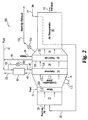
さて、図1を参照すると、本発明の一実施形態による燃料電池システム20が示されている。燃料電池システム20は、自動車用途に好適な燃料電池であると考えられているいわゆるPEM(プロトン交換膜)燃料電池90[a. k. a SPE (固体ポリマー電解質)燃料電池]に基づく。システム20は、炭化水素燃料、空気及び水の供給により有用な電気エネルギーを発生させるように構成されており、システム20は燃料改質器30、水気化器40、水性ガスシフト(WGS)反応器70、優先的酸化(PROX)反応器80及びPEM燃料電池90を含む。
Referring now to FIG. 1, a
燃焼燃料22及びPEMセル90からのアノード排気28は、空気26及び/又は24と一緒になり、得られるホットガス32は改質器30の加熱サイドを流通する。次いで、出口ガス34は気化器40の加熱サイドを通して送られる。燃焼ガスが水回収用の排出口54に到達する前に、ガス36中の残留熱は復熱器50内で捕捉される。水38は気化器40の気化サイドに送られ、燃料42は気化器40から出る蒸気44に混合され、次いで復熱器60内で加熱されて、改質器30への気体状流入物46を発生させる。
The
燃料42は典型的には液体炭化水素であり、任意の慣用の態様で蒸気44に添加されてもよい。例えば、別個の燃料気化器を設けて、蒸気44と混合する前に燃料を気化させてもよい。しかし、別個の燃料気化器は、低温始動時に加熱される必要がある追加の構成要素である。図示した実施形態において、別個の燃料気化器は用いていない。むしろ、液体燃料42は、燃料注入器又は噴霧器を用いて蒸気44に直接導入される。この態様において、過熱された蒸気44からの熱は燃料を気化させる作用をする。
The
改質器30は、気体状流入物46内の炭化水素及び蒸気を反応させて水素及び一酸化炭素を含有するリフォメート48を発生させる触媒を含有する改質サイドを有する蒸気改質反応器である。用いられる燃料42のタイプに応じて任意の種々の蒸気改質触媒を用いることができる。メタノール専用触媒は、リフォメート内で1%CO未満の低温変換用として知られている。他の触媒は広範囲の炭化水素類に対して適用可能であり、ほぼ平衡のCO濃度を有するガス混合物を発生させる。マイクロチャネル蒸気改質器で達成可能な高速の熱および物質移動の利点を得るために、高活性触媒が好ましい。適切な触媒の例示及びマイクロチャネル内で蒸気メタン改質を行う特定の技術は、米国特許6,488,838号明細書に記載されている。
The
リフォメート48は、復熱器60を通過して、その熱の幾分かが再捕捉される。リフォメート48は、PEMセル90を保護するために除去されるべき一酸化炭素などの不純物を含む。システム20において、リフォメート48を流路52、66及び68に沿って水性ガスシフト反応器70を通過させ、次いで酸素を供給するための空気64の添加後、優先的酸化反応器60を通過させることにより精製が達成される。水性ガスシフト反応及び優先的酸化反応の両者に対する冷却は、空気62及び60などの適切な冷却流体で与えられる。単一のブロワー又は空気源56をシステム空気需要のすべてに対して用いてもよいが、反応器70、80及び燃料電池90の変動する需要に対応するために個々のブロワーを空気供給ライン56の点線で示した部分に沿って用いることもできる。
The reformate 48 passes through the
PEM燃料電池230において、精製された水素68はアノードサイドに供給され、ここで水素は2個の水素イオンと2個の電子とに分割される。水素イオンはアノードからカソードへと、連続的に水で湿潤化される水素化固体電解質を通過することによって移動する。電子は、外部回路内でアノードからカソードへと通過して電力を供給する。カソードにおいて、水素イオン及び電子は空気58中の酸素と反応して、得られる水蒸気及び酸素枯渇空気を含有する排出流27は他の空気排出物と一緒になり、復熱器50内で加熱され、次いで26を介して燃焼域まで送られてもよい。
In the
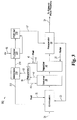
さて図2を参照すると、図1の燃料電池システム20の燃料改質サブシステム100が概略示されている。燃料改質サブシステム100は、始動時に改質器30及び気化器40の迅速加熱を提供し、次いで運転中のより温和な加熱を賄うように設計されている。より完全には後述するように、図示した実施形態において、始動時及び運転中の加熱を変動させる基本的な機構は、燃焼ガスの流量を変動させることである。空気入口25は、空気26及び必要に応じて(すなわち始動用)補助空気24を受け入れ、適切な1個又は複数個のブロワー(図示せず)を具備するミキサー110を通して空気を運ぶ。ミキサー110はさらに、燃料22を受け入れ、燃料/空気混合物を燃焼域111に提供する。燃焼域111の内面114は、燃料/空気混合物を点火するスパークプラグ112を受け入れるポートを含む。得られるホット燃焼ガスは、改質器30を通してその加熱サイド入口面116からその加熱サイド出口面118まで送られ、次いで気化器40を通してその入口面120からその出口面122まで送られる。気化器40の加熱サイドの出口36は、54で排気される前に空気復熱器50を通して通常送られるが、弁104は復熱器50をバイパスする補助排気102へのアクセスを与える。補助排気102を始動時に部分的に又は完全に用いて、復熱器50を貫通する燃焼ガス流に起因する追加の圧力降下を減少させ又は排斥することができる。
Referring now to FIG. 2, a
腐食を減少させるために、燃焼域111は内面114が非金属性であるように好ましくは構成される。例えば、金属製外シェルを内面が改質器111の入口面116に当接するポイントまで、絶縁材料で裏打ちしてもよい。ラボ設計の簡便さのために、システム200は、燃焼燃料として水素ガスを使用するように構成した。図10〜13に関して後述するように、ミキサー110を利用して、水素ガスを空気中に効率的に分配させて、チャンバ111内での均一な燃焼を達成した。他の実施形態において、燃料22はガソリンなどの液体燃料42と同じであり、スパーク燃焼用の液体燃料(すなわち、ガソリン)を注入する噴霧器又は燃料注入器をミキサー110の代わりに用いた。触媒燃焼又はスパークと触媒燃焼との組み合わせを改質器30及び気化器40を加熱するための熱を供給するために用いることもできた。
To reduce corrosion, the combustion zone 111 is preferably configured so that the
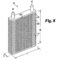
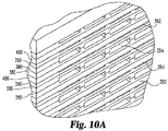
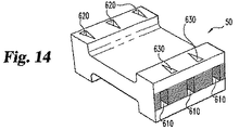
本発明の一側面において、用いられる改質器30及び気化器40は図8及び9に示すような交流パネル形状である。より詳細には、加熱サイドは改質器30及び気化器40のそれぞれの入口面116、120及び出口面118、122の間の多数の小さなフローチャネル425から構成される。これらの入口面及び出口面の長さL及び幅Wはそれぞれ、両面間の距離すなわちパネル厚Tよりも実質的に大きい。例えば、長さL及び幅Wはパネル厚Tの少なくとも2倍、3倍又は5倍であってもよい。
In one aspect of the present invention, the
改質器30及び気化器40は、一体に結合された複数の薄いシートのスタックから構築されてもよい。ここで、シートの凹部はデバイスを貫通する流路の少なくとも一部を画定する。例えば図8に示すように、改質器30は、頂部プレート及び底部プレートの間に挟持された加熱サイドシート420及び改質サイドシート430の交互スタックを含む。加熱サイドフローチャネル425は、加熱サイドシート420内に形成される。シート420、430の各々は、蒸気/燃料入口46及びリフォメート出口48に整合するヘッダーホール(図示せず)を有し、改質サイドシート430はホールの間に改質フローチャネル(図示せず)を画定する。
The
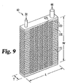
同様に、図9に示すように、気化器40もまた、加熱サイドシート520及び改質サイドシート530の交互スタックを含み、加熱サイドフローチャネル425は加熱サイドシート520内に形成される。シート520、530の各々は水入口38及び蒸気出口44と整合するヘッダーホール(図示せず)を有し、気化サイドシート530はホール間の気化フローチャネル(図示せず)を画定する。
Similarly, as shown in FIG. 9, the
改質器30(及び/又は気化器40)内で効率的な熱移動を増加させるために、改質フローチャネル(気化フローチャネル)又は加熱フローチャネル425のいずれか一方又は両者は、例えば約0.1インチ(0.254cm)未満又は0.5インチ(1.27cm)未満、又は0.025インチ(0.0635cm)未満のマイクロチャネル範囲の最小寸法を有する。別の側面において、加熱フローチャネル425及び/又は改質(又は気化)フローチャネルはそこを通るフローのレイノルド数(Re)が層流の範囲、例えば約2,000以下であるような寸法である。例えば、定常状態運転中の燃焼ガスフローはReが100〜500付近であってもよく、迅速始動時(後述する)の燃焼フローはReが1000付近であってもよい。改質器30及び気化器40として用いることができるこれら及び他の適切な流体処理ユニットに対するさらなる詳細は、本出願人の米国特許出願U. S. Application Ser. No.10/164,969(2002年6月6日出願)「流体処理デバイス及び方法」(PCT/US/02/18079)及び米国特許出願U. S. Application Ser. No.10/385,831(2003年3月11日出願)「温度制御を有するマイクロチャネル反応器」に記載されている。
In order to increase efficient heat transfer within the reformer 30 (and / or vaporizer 40), either or both of the reforming flow channel (vaporization flow channel) and / or the
図8及び9の交流パネル形状において、装置30、40を通る加熱サイドフローチャネル425は気化器又は改質フローチャネルよりも比較的短い長さである。例えば、それぞれ、気化又は改質フローチャネルの長さの1/4、1/8、1/16又は1/40であってもよい。圧力降下は流路長さと共に増加して、流路容積の減少と共に増加するから、この短い長さは、加熱サイドを貫通する圧力降下を大気圧近傍の比較的低レベルにし、特定の用途において有用なある種の設計上の利点を呈する。
In the AC panel configuration of FIGS. 8 and 9, the heated
例えばシステム200において、始動時の熱需要及び運転時の熱需要の両者は、燃焼ガスにより提供される。運転の1モードにおいて、迅速低温始動を達成するために必要な迅速加熱は、温度での安定運転中のマス流量と比較して大幅に増加したマス流量の燃焼ガスにより与えられる。特定の形態において、これは、始動時のマス流量を定常状態運転中の燃焼ガスのマス流量の少なくとも2倍、少なくとも3倍又は少なくとも5倍に増加させる。7〜10倍の増加もまた予測される。単一の可変速度ブロワー又は一対のブロワー(例えば、高低フローブロワー)を用いて、燃料22の増量に対応して流量を変動させることができる。場合によっては、始動時に、改質器30を取り巻くか埋め込まれている電気ヒーターなどの補助的な加熱を用いてもよい。
For example, in the
改質器の迅速加熱を達成するための追加の機構は、非常に高い燃焼ガス温度で運転することであり、いくつかの実施形態において、改質器30の設計は、燃焼ガス温度を改質器30の最大許容作動温度を大幅に超えさせるように選択される。図2のサブシステムにおいて、最高温度は改質器の入口面116において経験されるであろう。したがって、改質器の面116の温度は最大許容作動温度を超えることはできないから、面116における燃焼ガス温度に対する限界がある。これは、用いられる物質に依存する値であり、約1000時間連続運転後にクリープ及び/又は腐食に起因する劣化が顕著になる温度であるという。後述する実施例において、改質器は316Lステンレススチールから構成されているから、最大作動温度は約650℃であった。それにもかかわらず、改質器30は、短時間試験で顕著な劣化なしに1000℃付近の面116における燃焼ガス入口温度に対する耐性があった。これは、1000℃の温度に暴露されているにもかかわらず、改質器30の入口面116は1000℃に到達しなかったことを意味する。インコネル合金(Inconel alloy)などの実質的により高温の最大運転温度を有する物質からの改質器の製造もまた意図されるものである。
An additional mechanism to achieve rapid heating of the reformer is to operate at a very high combustion gas temperature, and in some embodiments, the design of the
入口面116でのガス温度が改質器の入口面116での最大作動温度を大きく超えることができる一つの理由は、改質サイドへの効率的な優れた熱移動である。別の理由は、パネルを通しての熱伝達(すなわち、面116から面118へ)である。パネル厚Tが比較的小さい場合には、このパネルを通しての面−面間熱伝達は、改質器の入口面116及び出口面118の間の温度差を大幅に減少させる。したがって、本発明のいくつかの側面において、改質器は、燃焼ガス入口温度が改質器30の最大許容作動温度よりも少なくとも100℃高い状態で運転する(少なくとも始動時)。別の側面において、これは少なくとも200℃又は300℃高い。
One reason that the gas temperature at the inlet face 116 can greatly exceed the maximum operating temperature at the inlet face 116 of the reformer is efficient heat transfer to the reforming side. Another reason is heat transfer through the panel (ie, from surface 116 to surface 118). When the panel thickness T is relatively small, the surface-to-surface heat transfer through the panel greatly reduces the temperature difference between the reformer inlet face 116 and
入手可能な非常に多種の空気移動設備があるが、費用(及び質量)は達成可能な圧力降下と共に一般に増加する。低コストにおいて、種々の廉価なファン及び遠心分離ブロワーが水柱5インチ(12.7cm)未満で、より一般的には水柱3インチ(7.62cm)未満で空気を提供することができる。ラジアルブロワーなどのわずかに高価なモデルは一般に水柱8〜12インチ(20.32cm〜30.48cm)で可能である。かなり高価な回生式ブロワーは水柱140インチ(355.6cm)又は5psi付近で可能であり、最後に最も高価で最も大きく最も重いオプションは、100psiまで又はそれ以上の圧力を生じさせるロータリーローブ(rotary lobe)、スライディングベーン(sliding vane)及び往復ピストンコンプレッサなどの容積式圧縮機及びブロワーである。比較的低い燃焼サイドの圧力降下を有するように燃料処理装置100を設計することは、携帯用途に顕著な利点を有する低コストで軽量の設備を用いることを可能とする。
There are a great variety of air moving equipment available, but the cost (and mass) generally increases with the achievable pressure drop. At low cost, various inexpensive fans and centrifugal blowers can provide air below 5 inches (12.7 cm) of water, and more typically below 3 inches (7.62 cm). Slightly expensive models such as radial blowers are generally possible with 8-12 inches of water (20.32 cm-30.48 cm). A fairly expensive regenerative blower can be around 140 inches (355.6 cm) or 5 psi of water, and finally the most expensive, largest and heaviest option is a rotary lobe that produces pressures up to 100 psi or higher Positive displacement compressors and blowers such as sliding vanes and reciprocating piston compressors. Designing the
さらに、ファンを出る空気馬力並びにファンモーターの電力要求は、流体流量及び提供される圧力増加に比例する。よって、水柱4インチ(10.16cm)での所与の空気フローを与えることは、5psi(水柱138インチ(350.52cm))で提供される同じフローのわずかに3%の力を要求するに過ぎない。自動車用途において、例えば、始動時に空気移動に必要な力は、自動車に搭載されるバッテリなどの代替エネルギー源により供給される必要がある。必要とされる電力が大きくなるほど、大型で重いバッテリが必要となる。逆に、始動時に燃焼ガスを駆動させるために消費される電力量が低いほど、始動時に必要であるバッテリ電力は小さい。例えば、50kWのPEM燃料電池用のリフォメートを提供する大きさのシステム100は、大気圧近傍で600scfm付近の始動空気流量を利用することができると予測される。水柱10インチ(25.4cm)で運転する75%効率のブロワーについて、これは、慣用の自動車用鉛蓄電池により到達可能な電力である約931W(ワット)を要するであろう。
Further, the air horsepower exiting the fan as well as the fan motor power requirements are proportional to the fluid flow rate and the pressure increase provided. Thus, giving a given air flow at 4 inches (10.16 cm) of water column requires only 3% of the force of the same flow provided at 5 psi (138 inches (350.52 cm) water column) . In automotive applications, for example, the force required for air movement at start-up needs to be supplied by an alternative energy source such as a battery mounted on the vehicle. The larger the power required, the larger and heavier the battery is required. Conversely, the lower the amount of power consumed to drive the combustion gas at startup, the smaller the battery power required at startup. For example, a
本発明の蒸気改質システムは、種々の設計に実装することができ、いくつかの設計は本明細書に記載のいくつかの利点を達成し得るが、すべての設計がすべての利点を達成するわけではないことは理解されたい。それにもかかわらず、本発明の一側面は、始動時の空気フローエネルギー需要が燃料電池の定常状態電気出力の約8%未満の量であるか、又は4%未満もしくは2%未満の量であるように構成された蒸気改質システム100を有することは理解されたい。追加の又は別の側面は、始動時の改質器及び気化器の加熱サイドを通しての圧力降下が実質的に1psi未満、例えば各ユニットを横断する水柱約10インチ(25.4cm)未満となるようにシステム100を構成することである。別の形態において、各ユニットを通しての圧力降下は各水柱8インチ(20.32cm)未満又は各水柱4インチ(10.16cm)未満である。さらに追加の又は他の側面は、大気温度から運転温度まで(例えば、50℃以下から600℃超過まで)の始動時間が約60秒未満、好ましくは30秒未満、より好ましくは約15秒未満であるようにシステム100を構築することである。
The steam reforming system of the present invention can be implemented in a variety of designs, and some designs can achieve some of the benefits described herein, but all designs achieve all of the benefits It should be understood that this is not the case. Nevertheless, one aspect of the invention is that the air flow energy demand at start-up is an amount that is less than about 8% of the steady state electrical output of the fuel cell, or an amount that is less than 4% or less than 2%. It should be understood that the
燃料処理システム100の始動時の制御変数は、気化器へ供給される燃料42及び水38の相対量、換言すれば改質器30への入口46での蒸気対炭素比(S:C)の選択を含む。本発明の一側面において、このS:C比は、システム100の定常状態運転中に用いられるS:C比よりも例えば4倍、6倍又は8倍、実質的に大きい。この増加したS:C比は種々の目的を奏する。第一に、蒸気の比率が高い場合には、図1のWGS反応器70及びPROX反応器80(又は後述する図3の膜分離器210)などの下流側水素精製構成要素に対して熱を移動させる。このことは、別の加熱源と一緒に用いられる場合には、これらを運転温度にまで到達させるために又はこれらの始動時間を短縮させるために用いることができる。
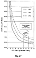
The control variable at the start of the
始動時の高いS:C比の別の目的は、改質器出口48におけるCO濃度を減少させることである。例えば、図17は、イソオクタン供給物の蒸気改質に対する種々の温度での平衡CO含有率とS:C比との間の関係を示す。18〜24の間の目標S:C比は、リフォメート中のCO含有率を4%未満に削減するように選択される。WGS反応器(又は他の精製設備)は温度に到達しているが、多量のCOを変換してリフォメートを精製することはできない。よって、リフォメート48のCO含有率を減少させることは、温度に達成する間に高WGS活性に対する需要を減少させる。
Another purpose of the high S: C ratio at start-up is to reduce the CO concentration at the
多くの用途において、S:C比、燃料供給速度及びブロワー速度を含む制御変数の各々は始動コントローラ(図示せず)により制御されることは理解されたい。コントローラは、システムの運転条件を分析するためのハードウェア(例えばコンピュータ)及びロジック(論理)(例えばソフトウェア)を含む。このコントローラは、例えば燃焼ガス流に沿って及びリフォメート48内にある温度センサなどのシステム全体の入力センサから適切な入力を受けることができ、始動S:C比及び燃焼ガス流量から定常状態パラメータへと変遷する時をロジックが決定する。
It should be understood that in many applications, each of the control variables, including S: C ratio, fuel supply rate and blower speed, is controlled by a start controller (not shown). The controller includes hardware (eg, a computer) and logic (eg, software) for analyzing the operating conditions of the system. The controller can receive appropriate inputs from system-wide input sensors, such as temperature sensors along the combustion gas flow and within the
蒸気改質サブシステム100は種々の燃料電池環境に適合することができることは理解されたい。例えば、別の実施形態に従う燃料電池システム200は図3に示されている。燃料電池システム200は、図1のシステム20と同じように機能して、システム200が水素膜分離器210を用いてリフォメート52を精製することを不要にする。膜は典型的には、選択的に水素を通過させるフィルム又は物質である。保持液(retentate)サイドと呼ばれる膜の流入サイドは、浸透液(permeate)サイドと呼ばれる流出サイドよりも典型的には高い圧力である。浸透液サイドと保持液(retentate)サイドとの間の圧力差は、水素の分離を駆動させることを補助する。適切な膜としては、例えば、パラジウム及びパラジウムと銀又は銅の合金の薄いチューブ又は箔を挙げることができる。水素浸透液と呼ばれる膜210を出る精製水素流214は、クーラー220内で空気流56により冷却された後、燃料電池230に供給される。膜又は保持液(retentate) 212を通過しなかった物質は、処理熱を提供するために燃焼用に再循環されてもよい。
It should be understood that the
また別の実施形態において、アルカリ燃料電池、リン酸燃料電池、溶融カーボネート燃料電池などの異なるタイプの燃料電池、例えば、図4は固体酸化物燃料電池310を使用するシステム300を示す。
In yet another embodiment, FIG. 4 shows a
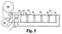
これまで記載してきた燃料改質はただ1個の燃料改質器30を利用していたが、本願は、多数の個々の燃料改質器が用いられる場合も意図している。図5は、単一の気化器40と直列の一群の燃料改質器30を運転するための一態様を概略的に示す。空気は、ダンパー176の位置に応じて大容量ブロワーB2又は小容量ブロワーB1のいずれかによって、加熱経路170に沿って供給される。迅速始動に対して位置づけられる場合、図5に示したように、大容量ブロワーは空気を経路170に下向きに流し、一連のパネル型改質器30を通して流す。一連の燃料注入ポート172は、各改質器30及び気化器40から上流側にある。これらのポート172は燃料を供給し、次いで燃料は各パネルの前方で触媒的に又はスパーク燃焼して各改質器30を加熱する。加熱経路170に沿った温度を測定することができ、注入器172の各セットに供給された燃料の量はすべての改質器30の均一な加熱を確実にするように制御することができる。気化器40を通過後、燃焼ガスは戻り経路174を辿り、直列の第1の改質器30から上流側で空気と熱を交換する。
Although the fuel reforms described so far have utilized only one
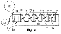
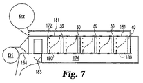
図6及び7は、通常運転中には直列フローで運転するが始動時には平行フローで運転するように構築された一群の改質器30及び1個の気化器を示す。図6に示すように、始動時に大容量ブロワーB2が作動しており、燃料は1セットのポート173を通して供給されている。得られる燃焼ガスは、次いで改質器30及び気化器40を通って平行に流れる。
FIGS. 6 and 7 show a group of
始動後、一連のダンパー180、181及び183、184は、改質器30を小容量ブロワーB1から下流側の連続流に置くように作動し、燃料は図5に関して上述したように注入器172を介して供給される。
After start-up, a series of
さて図10〜13を参照すると、ミキサー110の追加の特徴が示されている。上述したように、燃焼の前に水素ガスを空気に効率的に混合するためにミキサー110は図2のラボ型を用いた。
10-13, additional features of the
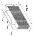
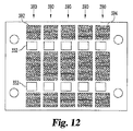
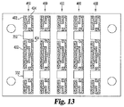
しかし、より一般的には、2種の流体を効率的に混合することが必要である任意の流体処理環境中でミキサー110を用いることができる。ミキサー110は、パネル形状のものであり、気化器40及び改質器30に関して上述したように一体的に結合された複数の薄いシートのスタックから構築されている。図11〜13は、個々のシート380、390、400を示し、凹部(エッチングにより形成された)を示すためにクロスハッチングが用いられている。米国特許出願U. S. Application Ser. No.10/164,969号により完全に記載されているように、多数(この場合は5)の個々のミキサー110用のシートが単一のシムの上に並列に存在しており、結合プロセスを促進し、結合後に分離される。結合は、拡散接合でもよく、各シムの左右のマージンは、拡散接合中に圧力を付与するための外部ラムと整合するホールを有する。シートは図10Aに示されるようにスタックされ、各シートは、スタック中で整合して第1の流体ヘッダーを形成する一対のヘッダーホール352を有する。
More generally, however, the
第2の流体フローチャネル354は、背面(図示せず)に入口を有し、混合面350に出口を有し、一対の対面するシート380から構築される。第1の流体フローチャネル392への入口はミキサー110の内部にあり、出口は混合面 350上で第1の流体チャネル354の出口と交互に配置されている。示した実施形態において、第1の流体チャネル392は第2の流体チャネル354よりも実質的に狭くなるように構成されていて、これらは混合面350上のこれらの出口において支持リブ394を含む。一形態において、第1の流体フローチャネル392は、第2の流体フローチャネル392の全高の約1/4である。
The second
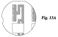
運転時に、第1の流体はミキサー110の頂部(図10視)に入り、内部分配シート400の蛇行チャネル404内を通過する。蛇行チャネル404は、第1の流体を背面に向かって、ミキサー110の背面内部にあるホール402まで搬送する。第1の流体は、シート400内のホール402を通って第1の流体フローチャネル392内に滴下し、次いでチャネル392の長さ方向に、混合面350における出口まで流れる。混合面350上の異なる流体チャネルの交互に配置された出口は、流体を効率的に混合する作用をする。さらに、経路392及び354は、デバイスを貫通して熱接触状態にあり、不均衡配分を引き起こすであろう温度勾配を減少させる。
During operation, the first fluid enters the top of the mixer 110 (see FIG. 10) and passes through the serpentine channel 404 of the
フローチャネルは、両方の流体のフローが層流になるようにマイクロチャネル規模であり、シムは熱移動の大半が並流(co-current flow)であるチャネル354と392との間で生じるように設計されている。高さが小さいほど熱移動係数を増加させ、マイクロチャネル内の熱移動はチャネルの高さに直接関連するので、これはチャネル392の高さを分配チャネル404の高さよりも小さく設計することにより達成され得る。これはさらに、チャネル392内での流体1に対する圧力降下を集中させるように作用し、さらに均一な分配に寄与する。
The flow channel is microchannel scale so that the flow of both fluids is laminar, so that the shim occurs between
ミキサー110は種々の用途及び2種類の流体の均一な制御された混合を達成するために必要であるときには基本的にいつでも適用可能であることは理解されるべきである。一つの用途は、燃焼(触媒的又は火炎燃焼のいずれか)に先立ち、2種類の流体を混合することである。空気と燃料との均一な混合物を提供することにより、触媒上での熱の発生は高度に均一であり、触媒を劣化させるかその性能を減少させる触媒上での局所的温度変動を防止すると考えられる。
It should be understood that the
別の例は、蒸気改質器の前段での蒸気と気化燃料との混合である。蒸気改質器に反応物質を導入する前に、蒸気と燃料との均一な混合物及びコークス化を導く局所的に低い蒸気比率を有していることが必要である。均一な混合は、このリスクを減少させ、蒸気を発生させる必要性を減少させることに起因してエネルギーを節約することができる。 Another example is the mixing of steam and vaporized fuel before the steam reformer. Before introducing the reactants into the steam reformer, it is necessary to have a locally low steam ratio that leads to a homogeneous mixture of steam and fuel and coking. Uniform mixing can reduce this risk and save energy due to reducing the need to generate steam.
別の例は、往復ピストンエンジンへのガスの導入前に混合することである。いくつかの用途において、主としてNOx減少のために、ピストンエンジンへ流入する空気への気体状添加剤の導入が考えられる。この添加されたガスは、水素又は改質器からのリフォメート又はエンジンに循環して戻される排出ガスであってもよい。ディーゼルエンジンの場合には、このデバイスは、流入する空気及び再循環した排出ガスの均一な混合物を与えるであろう。これは、煤煙発生領域において及びエンジン出力で負の影響が生じる前に、より多量の排出ガス再循環を許容できる(化学量論的空気により近い状態で運転する能力)利点を有するであろう。 Another example is mixing before the introduction of gas into the reciprocating piston engine. In some applications, the introduction of gaseous additives into the air entering the piston engine is conceivable, primarily due to NOx reduction. This added gas may be hydrogen or reformate from the reformer or exhaust gas that is circulated back to the engine. In the case of a diesel engine, this device will provide a uniform mixture of incoming air and recirculated exhaust gas. This would have the advantage of allowing a greater amount of exhaust gas recirculation (ability to operate closer to stoichiometric air) in the soot generation area and before negative effects occur on the engine output.
別の用途は、高められた温度のガス流の湿潤化である。蒸気をホットフローガス流に添加することが望ましいならば、蒸気を流体1として流れている流2に添加してもよい。この用途において、復水が均一なフロー条件を乱すかもしれないので、温度はデバイス内部での復水を避けるようにすべきである。
Another application is the wetting of elevated temperature gas streams. If it is desired to add steam to the hot flow gas stream, steam may be added to
別の用途は、流体に対する混合時間を短縮することである。いくつかの用途において、2種類の反応体の混合時間は、望ましくない副反応の程度に影響を与え得る。反応体の迅速な混合は、所望の生成物の收率を最大にする。これは通常、高剪断ミキサーを用いることによって達成される。この混合デバイス110を通してこのようなプロセスに反応体を供給することによって、所望の混合を達成するための時間を最小にすることができる。流体を混合することが困難な場合には、より短い時間内で完全に均一な混合を達成するために、デバイスを機械的ミキサーと一緒に用いることができる。これは、出力が流体に対する混合時間に関連するプロセスの生産性を増加させるだけでなく、混合集約プロセスに関連する時間及びエネルギーコストを削減することができる。
Another application is to reduce the mixing time for the fluid. In some applications, the mixing time of the two reactants can affect the degree of undesirable side reactions. Rapid mixing of the reactants maximizes the yield of the desired product. This is usually accomplished by using a high shear mixer. By supplying reactants to such a process through the
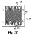
さて図14、15及び15Aを参照すると、図2の復熱器50の追加の特徴が示されている。復熱器は、上述のように複数の薄いシートのスタックとして構成されるが、単一のシム(図15)を用いるだけである。シムのエッチングされたサイドは、ヘッダーが互いに面するように、次のシムのエッチングされたサイドに面するように組み立てられる。このようなシム対は、ヘッダーホール615に対して開いている単一の流路650を画定する。この流路650は、シム対がスタック内で図15に示すように底部シムと一緒に方向付けられているかあるいは180゜回転しているか(エッチングされたサイドが上に向いたまままである)に応じて、第1の流体流路もしくは第2の流体流路のいずれかとして機能する。シムが180゜回転する場合には、すべてのヘッダーホール615、625は整合し、スタックの隣接する層内で、流路650に対して開いているヘッダーホール615のセットは流路650に対して閉じているヘッダーホール625と整合することは理解されるべきである。
Referring now to FIGS. 14, 15 and 15A, additional features of the
したがって、図14は、図15のシム対の交互スタックを有するように構築されたデバイスを示す。マニフォールドが加えられて第1の流体用の入口620及び出口630を作り、他のヘッダーホールのセットの底辺640から切り出された部分は第2の流体用の入口610及び出口(図示せず)を作る。シムの各サイドには奇数個のホール615、625(この場合には各サイドに5個)があるので、3個の第1の流体入口620と2個の第1の流体出口630(逆もまた同じ)がある。同様に、向流熱交換器形状内に3個の第2の流体入口610とただ2個の出口(図示せず)がある。
Accordingly, FIG. 14 shows a device constructed to have an alternating stack of the shim pairs of FIG. Manifolds are added to create a first
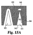
図15Aに示すように、ヘッダーホール625及び615は高いアスペクト比構造である。特に、これらは底辺640の長さの少なくとも2倍の高さを有する三角形である。ホール615は、フローチャネル650への各流体用の入口として作用する2個のより長い側辺642を有し、比較的短い底辺640はフローチャネル650から比較的離れて配設されている。複数の支持リブ644は、流路650に開口を広げ、支持構造646は三角形の頂点である。リブ644及び構造646は、スタックの拡散接合構築の間、隣接するシムの下側と結合し、交互の層へのフローからヘッダーホールをシールすることを保証する。
As shown in FIG. 15A, the header holes 625 and 615 have a high aspect ratio structure. In particular, these are triangles having a height at least twice the length of the
この高いアスペクト比ヘッダーホールを用いることで、流路650の入口(および出口)領域における断面積(すなわち、支持リブ644の間でエッジ642に隣接する流路650の部分)を増加させる。目的は、これらの入口(または出口)領域(すなわち、ヘッダー615の各々に対する)にわたる流体フローに対する累積断面積を、流路650の中心により近い(すなわち、流路650の出入口領域から離れる)流体フローに対する断面積により近く符合させることにある。断面積を符合させることは、流体速度を符合させ、チャネル650を通るフロー全体に対する入口損失および出口損失を減少させる。これらの断面積を正確に符合させることは現実的ではないかもしれない。一形態において、マイクロチャネルへの入口(または出口)領域内での累積断面積が、入口(または出口)領域から実質的な距離だけ離隔したマイクロチャネル内のフローの断面積の約50%以内にあるように、ヘッダーは設計される。より好ましくは、約30%、20%または10%以内である。
By using this high aspect ratio header hole, the cross-sectional area in the inlet (and outlet) region of the channel 650 (ie, the portion of the
例えば、向流マイクロチャネル空気−空気復熱器に対する従来の設計は、四角形の一つの側辺だけが流路に対して開いていた四角形ヘッダーホールを用いていた。結果として、入口および出口領域における速度は、流路熱交換領域の中央における速度の2倍以上であった。流路650の入口および出口での速度変化を減少させることは、圧力降下を減少させる作用をする。例えば、図示した層流熱交換器は、1atm圧力での2種の空気の等モルフロー間で80%を超える効率とすることが可能である。このとき、各空気流での圧力降下は水柱約2.5インチ(6.35cm)未満である。
For example, conventional designs for counterflow microchannel air-air recuperators have used square header holes where only one side of the square is open to the flow path. As a result, the velocity at the inlet and outlet regions was more than twice the velocity at the center of the flow path heat exchange region. Reducing the speed change at the inlet and outlet of the
より一般的には、これらのヘッダーホールは、マイクロチャネルへ入る圧力損失およびマイクロチャネルから出る圧力損失が問題となる任意のマイクロチャネルデバイスで用いることができる。 More generally, these header holes can be used in any microchannel device where pressure loss into and out of the microchannel is an issue.
本発明の実施形態のいくつかの特定の特徴を示す特別の実施例を参照されたい。しかしながら、これらの実施例は説明のために与えられているものであって、本発明の範囲を制限するものではないことは理解されたい。 Reference is made to specific examples illustrating some specific features of embodiments of the present invention. However, it should be understood that these examples are given for illustrative purposes and do not limit the scope of the invention.
燃料処理装置を図2に従って構築した。改質器30を316Lステンレススチールシムのスタックから構築した。スタック内の各改質サイド流路をこれらのシムから構築した。触媒フェルトに必要なギャップを与えるセンタースペーサーを、フェルトを保持しフェルトを通過する反応物質(reactant)流路を画定する支持リブを有する対面するエッチングされたシムの間にサンドイッチした。反応物質流路を形成する同様の3種のシム技術は、本出願人の米国特許出願U. S. Application Ser. No. 10/385,831(2003年3月11日出願)により完全に記載されている。拡散接合の後、パネルのエッジにアクセススリットを切り、面の間でスペーサーシムにフェルトを長手方向にスライドさせ、次いで、一片の金属でエッジを再度シールすることにより、触媒フェルトをスタックに追加した。一対の対面するシムから燃焼サイドを形成し、0.02インチ(0.0508cm)深さの燃焼フローチャネルを作った。48セットのこれらのシムをスタックして、3.6インチ(9.144cm)高さ、2インチ(5.08cm)幅、0.45インチ(1.143cm)厚のコアシムスタックを有する反応器を形成した。反応器の各サイドに内部ヘッダーを含ませて、2.5インチ(6.35cm)まで幅を増加させる。
A fuel processor was constructed according to FIG.
気化器40もまた、316Lステンレススチールシムのスタックから構築した。一対の対面するエッチングされたシムは蒸気/水流路を提供し、一対の対面するエッチングされたシムは米国特許出願U. S. Application Ser. No. 10/164,969(2002年6月6日出願)により完全に記載されているような燃焼流路を提供した。気化サイド上では、水チャネルを0.005インチ(0.0127cm)深さにエッチングし、蒸気チャネルは、組み合わされたエッチング深さ0.01インチ(0.0254cm)を有していた。燃焼サイドは、組み合わされたエッチング深さ0.01インチ(0.0254cm)のチャネルを有していた。気化器を、29の燃焼ガス層で挟まれた28の蒸気/水層から構築した。結合して、頂部プレートおよび底部プレートを組み込んだ後、気化器は、約5.25インチ(13.335cm)長さ、3インチ(7.62cm)幅、0.185インチ(0.4699cm)厚であった。
The
燃料42はイソオクタンであり、ガソリンを模するために選択された。研究室での利便のために、燃焼燃料22は水素ガスとした。
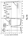
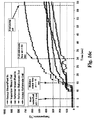
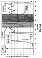
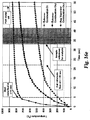
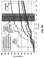
2種の高速始動試験に対するリフォメートフローおよびシステム温度は図16a〜fに示す。燃焼プロセスに対する空気流量は1000slpmであった。100slpmの水素フローを、マイクロチャネルミキサーを用いて空気流に混合させ、スパークプラグで着火して必要な熱を発生させた。図16a〜cは、バルブ108を閉じ、及び/又は復熱器バイパス106を運転しない状態での試験を表す。図16d〜fは、復熱器バイパス106が運転状態にある場合の比較結果を表す。蒸気をシステムからの非凝縮性ガスで置換する場合に、システムから約12秒の短いパルスのガスが流れる。完全なリフォメートフローは、これらの2種の試験で30秒(図16a)と22秒(図16d)に生じた。22秒の始動試験では、フローを分流させてサンプルラインをフラッシュし、次いで、排気されたサンプルシリンダを充填する。リフォメートのガスクロマトグラフィー分析は、72.3% H2、6.1% CO、19.1% CO2および0.24% CH4の乾燥基準組成を与えた。低い変換率(69%)および平衡CO濃度(4%が平衡であった)よりも高いCO濃度は、高速始動試験に関係ない触媒問題に起因するものと考えられた。燃焼サイド(図16b、16e)での温度は、パネル断面を等間隔に横断する8個の熱電対の平均であり、改質サイド(図16c、16f)上の温度は、単一の熱電対を表す。リフォメート製造における振幅は、燃料ポンプのピストンストロークの期間に対応する。パルスダンパーは、脈動を排除することができるが、過渡的応答を遅くし得る。
The reformate flow and system temperature for the two fast start tests are shown in Figures 16a-f. The air flow rate for the combustion process was 1000 slpm. A 100 slpm hydrogen flow was mixed into the air stream using a microchannel mixer and ignited with a spark plug to generate the necessary heat. FIGS. 16a-c represent tests with
復熱器バイパスでの試験はリフォメート製造を速やかに達成したが、これがバイパスの結果であったとすれば、改質器での燃料のより早い到達を生じた第2の試験での燃料注入ラインにおける空の容積が減少したか否か、明らかではない。復熱器バイパスを利用する同じシステムでの引き続いての試験(データを示さず)は、始動が12秒で達成された。これらの引き続いての試験において、燃料ポンプは、通常の速度よりも速い速度で始動し、燃料改質が生じた形跡があったならば、燃料ポンプをダイヤルで調節して定常状態速度まで下げた。 Tests in the recuperator bypass achieved reformate quickly, but if this was the result of the bypass, in the fuel injection line in the second test that resulted in faster arrival of fuel in the reformer It is not clear whether the empty volume has decreased. Subsequent testing on the same system utilizing recuperator bypass (data not shown) was accomplished in 12 seconds. In these subsequent tests, the fuel pump was started at a speed faster than normal, and if there was evidence of fuel reform, the fuel pump was adjusted with the dial to a steady state speed. .
始動時には、蒸気:炭素(S:C)比(100%燃料フローで)が18:1〜24:1の範囲となるように目標を置いた。上述のように、蒸気のこの高い比率は下流側のWGS反応器およびPROX反応器に熱を与え、運転温度まで上昇させるであろう。下流側の反応器の概算質量および計画された蒸気比率に基づいて、WGS反応器およびPROX反応器は、このS:C範囲での過剰の熱で運転温度まで約60秒以内に達し得ると予測される。 At start-up, targets were set so that the steam: carbon (S: C) ratio (at 100% fuel flow) was in the range of 18: 1 to 24: 1. As mentioned above, this high proportion of steam will heat the downstream WGS and PROX reactors and raise them to the operating temperature. Based on the approximate mass of the downstream reactor and the planned steam ratio, the WGS and PROX reactors are predicted to be able to reach the operating temperature in about 60 seconds with excessive heat in this S: C range Is done.
定常状態において、燃焼サイド流量は100〜110slpm(ref 21.1℃)であり、圧力降下は反応器を横断する方向で1.1インチ(2.794cm)以下H20であり、気化器を横断する方向で0.14インチ(0.3556cm)以下H20であった。30秒での現行の迅速始動試験において、完全なリフォメートが製造される場合、燃焼サイド空気流量は1000slpmに維持され、水素は経時的に減少して燃焼入口を1000℃未満に維持する。反応器パネルおよび気化器パネルを横断する圧力降下は、高フロー高温条件下でそれぞれ14インチ(35.56cm)および8インチ(20.32cm)であった。
In steady state, the combustion side flow rate is 100-110 slpm (ref 21.1 ° C.), the pressure drop is 1.1 inches (2.794 cm) or
いくつかの変更が現行のシステム性能を改良するために計画されている。第一に、反応器をインコネル(Inconel)合金で製造し、高温運転を可能とする。これは、改質器の熱質量を現行の値の1/3未満まで減少させるであろう。反応器質量の追加の40%は、設計変更により排除されると予測される。用いられている総空気フローは、より低い空気流量でより高い燃焼温度を用いることにより減少するであろう。始動時(並びに定常状態で)の空気フロー容量および圧力要求を減少させるために、燃焼ガスサイド上での減少した速度と一緒により高い温度駆動力が利用されるであろう。現在の目標は、50kWeシステムに対する始動空気フローを5インチ(12.7cm)〜10インチ(25.4cm)H20範囲の最大圧力降下を伴う450〜600scfmフロー範囲にすることである。10インチ(25.4cm)H20で600scfmを与える75%効率のブロワーに対する機械的力の入力は931wであり、空気移動は慣用の自動車用鉛蓄電池の及ぶ範囲内にある。
[結語]
本発明を図面および上記に詳細に記載してきたが、これらは発明の説明のためであり、本発明を限定するものではない。わずかに数種の実施形態だけを示し記載してきたが、本発明の範囲内で行われる変化、均等物および変形は保護されるべきである。本明細書に記載した実験、実験例または実験結果は本発明の説明を意図するものであり、本発明の範囲を何ら限定するものではない。さらに、いかなる理論、作用機序、検証または本明細書に記載の知見は、本発明の理解を深めることを意図するものであって、このような理論、作用機序、検証または知見によって本発明を限定するものではない。
Several changes are planned to improve current system performance. First, the reactor is made of an Inconel alloy to enable high temperature operation. This will reduce the thermal mass of the reformer to less than 1/3 of the current value. An additional 40% of reactor mass is expected to be eliminated by design changes. The total air flow used will be reduced by using a higher combustion temperature with a lower air flow rate. In order to reduce the air flow capacity and pressure requirements at start-up (and in steady state), a higher temperature driving force along with the reduced speed on the combustion gas side will be utilized. The current goal is to bring the starting air flow for a 50 kWe system to a 450-600 scfm flow range with a maximum pressure drop in the 5 inch (12.7 cm) to 10 inch (25.4 cm)
[Conclusion]
Although the present invention has been described in detail in the drawings and above, these are for purposes of illustration only and are not intended to limit the invention. Although only a few embodiments have been shown and described, changes, equivalents and variations made within the scope of the invention should be protected. The experiments, experimental examples or experimental results described in this specification are intended to explain the present invention and do not limit the scope of the present invention. Further, any theory, mechanism of action, verification or knowledge described herein is intended to deepen the understanding of the present invention, and the present invention is based on such theory, mechanism of action, verification or knowledge. It is not intended to limit.
よって、本記載の特定例および添付図面に本発明の範囲を限定すべきでない。むしろ、本発明の範囲は添付の特許請求の範囲を参照することによって評価されるべきである。特許請求の範囲を読む際に、「1の」「単数の」「少なくとも1の」および「少なくとも一部」などの用語は、特にことわらない限り、ただ一つのものに限定することを意図しない。さらに、用語「少なくとも一部」及び/又は「一部」が用いられる場合、特にことわらない限り、一部及び/又は全体を含み得る。同様に、電気デバイスまたは流体処理ユニットに関して、用語「入口」または「出口」が用いられる場合、文脈に応じて単数形または複数形および1以上の単独チャネルまたは流体ラインを含むことを理解すべきである。最後に、本明細書中に引用したすべての刊行物、特許および特許出願は、たとえ特別におよび個別に参照により全体として本明細書に組み込まれるべきことが示されていたとしても、本明細書の開示と矛盾しない限度において参照されるべきである。 Accordingly, the scope of the invention should not be limited to the specific examples described herein and the accompanying drawings. Rather, the scope of the present invention should be evaluated by reference to the appended claims. When reading the claims, terms such as “one”, “single”, “at least one” and “at least part” are not intended to be limited to only one unless specifically stated otherwise. . Further, where the term “at least part” and / or “part” is used, it may include part and / or whole unless stated otherwise. Similarly, with respect to electrical devices or fluid treatment units, it should be understood that where the term “inlet” or “outlet” is used, it includes the singular or plural and one or more single channels or fluid lines depending on the context. is there. Finally, all publications, patents and patent applications cited herein are hereby incorporated by reference herein even if specifically and individually indicated to be incorporated herein by reference in their entirety. To the extent consistent with the disclosure of
Claims (53)
反応器の加熱サイドを流通する燃焼ガスで反応器の改質サイドを加熱することにより改質反応器を始動させる始動工程と;
次いで、反応器を運転させて、加熱サイドを流通する燃焼ガスからの熱で吸熱改質反応を改質サイドで行うことにより、リフォメート流を発生させる工程と;
を含み、始動時に加熱サイドを通る燃焼ガスのマス流量は、運転中に加熱サイドを通る燃焼ガスのマス流量の少なくとも約5倍である、プロセス。 Providing a fuel reforming reactor and a fuel cell system including at least one blower for selectively conveying combustion gases through the heating side of the reforming reactor at different mass flow rates;
A starting step of starting the reforming reactor by heating the reforming side of the reactor with combustion gas flowing through the heating side of the reactor;
Next, a step of generating a reformate flow by operating the reactor and performing an endothermic reforming reaction on the reforming side with heat from the combustion gas flowing through the heating side;
A process in which the mass flow rate of the combustion gas through the heating side during start-up is at least about 5 times the mass flow rate of the combustion gas through the heating side during operation.
燃料電池用の水素を蒸気及び炭化水素類から発生させるように作用可能である蒸気改質器;および
蒸気を該蒸気改質器に供給するための気化器;を具備し、該蒸気改質器は第1面及び第2面を画定するパネルであり、各面の長さ及び幅は両面間の距離よりも実質的に大きい、システム。 Fuel cell;
A steam reformer operable to generate hydrogen for the fuel cell from steam and hydrocarbons; and a vaporizer for supplying steam to the steam reformer, the steam reformer comprising: Is a panel defining a first side and a second side, the length and width of each side being substantially greater than the distance between the two sides.
燃料電池用リフォメート流出流へ気体状流入蒸気を変換させるための蒸気改質器と;
蒸気改質器の加熱サイドよりも下流側にある加熱サイドを有し、過熱された蒸気を提供するための気化器と;
気化器及び改質器の間にあり、液体燃料を過熱された蒸気に注入して改質器への気体状流入流を発生させるための燃料注入器とを具備するシステム。 With fuel cells;
A steam reformer for converting gaseous inflow steam into a fuel cell reformate effluent;
A vaporizer for providing superheated steam having a heating side downstream of the heating side of the steam reformer;
A system comprising a fuel injector between the vaporizer and the reformer for injecting liquid fuel into the superheated vapor to generate a gaseous inflow to the reformer.
該改質器の改質サイドよりも上流側にある気化サイド、及び該改質器の加熱サイドよりも下流側にある加熱サイドを有する水気化器と;
気化サイド及び改質サイドの間で流体連通させる燃料注入器と;を具備し、
該燃料注入器は、燃料改質運転中に液体燃料を過熱された流に噴霧して、改質サイドへの気体状流入流を発生させ; 気化器及び蒸気改質器の少なくとも一方は加熱サイド流路への入口を画定する入口面及び加熱サイド流路への出口を画定する出口面を画定し、各面は両面間の距離よりも実質的に大きな長さ及び幅を有する、システム。 A steam reformer having a reforming side and a heating side;
A water vaporizer having a vaporization side upstream of the reforming side of the reformer and a heating side downstream of the heating side of the reformer;
A fuel injector in fluid communication between the vaporization side and the reforming side;
The fuel injector sprays liquid fuel into a superheated stream during a fuel reforming operation to generate a gaseous inflow to the reforming side; at least one of the carburetor and the steam reformer is a heated side A system defining an inlet surface defining an inlet to the flow channel and an outlet surface defining an outlet to the heated side flow channel, each surface having a length and width substantially greater than the distance between the two surfaces.
蒸気改質器の加熱サイドよりも下流側にある加熱サイドを有し、蒸気改質器用の蒸気を発生させるための水気化器と;
ホットガスを蒸気改質器の加熱サイドに供給するための燃焼域と;を具備し、
蒸気改質器の加熱サイド及び気化器の加熱サイドはそれぞれ、一対の面の間に多数の流路を有し、各面の長さ及び幅は両面間の距離よりも実質的に大きい、オンデマンド燃料改質システム。 A steam reformer having a heated side;
A water vaporizer having a heating side downstream from the heating side of the steam reformer and for generating steam for the steam reformer;
A combustion zone for supplying hot gas to the heating side of the steam reformer;
Each of the heating side of the steam reformer and the heating side of the vaporizer has a number of channels between a pair of surfaces, the length and width of each surface being substantially greater than the distance between the two surfaces. Demand fuel reforming system.
該整合されたヘッダー開口は高い形状アスペクト比を有し、該第1マイクロチャネル流路への出入口領域でのフローの累積断面積は出入口領域からかなりの距離だけ隔たっている該第1流路におけるフローの断面積の約50%以内である、流体処理デバイス。 A stack of thin sheets joined together, the stack including alternating recessed sheets having header openings aligned at opposite ends, wherein the recesses in the sheets are the first recesses of the plurality of header openings; Defining a plurality of first microchannel channels therebetween and defining a plurality of second microchannel channels between other recesses of the plurality of header openings;
The aligned header opening has a high shape aspect ratio, and the cumulative cross-sectional area of the flow at the inlet / outlet region to the first microchannel channel is in the first channel separated by a significant distance from the inlet / outlet region. A fluid treatment device that is within about 50% of the cross-sectional area of the flow.
スタック中において第1及び第2流路は熱接触状態にあり;
それぞれの流路を流出する際に第1及び第2の流体が混合するように第1流路の出口は第2流路の出口と交互に配置されている、混合デバイス。 A device for mixing a first fluid stream and a second fluid stream, comprising a stack of a plurality of thin sheets joined together, the stack comprising alternating recessed sheets, wherein the recesses in the sheets are Defining at least a portion of a number of first flow paths for conveying a first fluid to the outlet face of the stack and at least a portion of a number of second flow paths for conveying a second fluid to the outlet face of the stack; The sheet further includes at least one set of alignment header holes that distribute the first fluid to the first flow path;
The first and second flow paths are in thermal contact in the stack;
A mixing device wherein the outlets of the first channel are alternately arranged with the outlets of the second channel so that the first and second fluids mix as they flow out of each channel.
Applications Claiming Priority (4)
| Application Number | Priority Date | Filing Date | Title |
|---|---|---|---|
| US47113003P | 2003-05-16 | 2003-05-16 | |
| US47128603P | 2003-05-16 | 2003-05-16 | |
| US54610704P | 2004-02-18 | 2004-02-18 | |
| PCT/US2004/015402 WO2004104140A1 (en) | 2003-05-16 | 2004-05-17 | Rapid start fuel reforming systems and techniques |
Publications (1)
| Publication Number | Publication Date |
|---|---|
| JP2007504635A true JP2007504635A (en) | 2007-03-01 |
Family
ID=33479713
Family Applications (1)
| Application Number | Title | Priority Date | Filing Date |
|---|---|---|---|
| JP2006533140A Pending JP2007504635A (en) | 2003-05-16 | 2004-05-17 | Fast start fuel reforming system and technology |
Country Status (6)
| Country | Link |
|---|---|
| US (3) | US7763217B2 (en) |
| EP (1) | EP1629068A4 (en) |
| JP (1) | JP2007504635A (en) |
| KR (1) | KR20060007376A (en) |
| CA (1) | CA2520597A1 (en) |
| WO (1) | WO2004104140A1 (en) |
Families Citing this family (31)
| Publication number | Priority date | Publication date | Assignee | Title |
|---|---|---|---|---|
| US7520917B2 (en) | 2004-02-18 | 2009-04-21 | Battelle Memorial Institute | Devices with extended area structures for mass transfer processing of fluids |
| US20070042237A1 (en) * | 2005-08-19 | 2007-02-22 | Gibbard Research & Development Corp. | Mixed reactant fuel cell system with vapor recovery and method of recovering vapor |
| CN101033989B (en) * | 2006-03-10 | 2010-11-10 | 罗瑞真 | Environment monitoring device and method |
| US20070277438A1 (en) * | 2006-05-30 | 2007-12-06 | Brehon Energy Plc | System and method for producing a hydrogen enriched fuel |
| FI119490B (en) | 2006-06-22 | 2008-11-28 | Waertsilae Finland Oy | Preheating arrangement in a fuel cell plant |
| US7862633B2 (en) * | 2007-04-13 | 2011-01-04 | Battelle Memorial Institute | Method and system for introducing fuel oil into a steam reformer with reduced carbon deposition |
| EP2014615A1 (en) * | 2007-07-05 | 2009-01-14 | Electro Power Systems S.p.A. | Steam-reforming-based fuel-processing apparatus and method for fast start-up thereof |
| US8092558B2 (en) * | 2008-01-22 | 2012-01-10 | Asemblon, Inc. | Microchannel reactor module for hydrogen release |
| US7882707B2 (en) * | 2008-08-04 | 2011-02-08 | Lawrence Dean Leabo | Refrigeration hot gas desuperheater systems |
| EP2386129B1 (en) * | 2009-01-07 | 2020-04-29 | Powercell Sweden AB | Fuel processor and method for generating hydrogen rich gas |
| US8715875B2 (en) * | 2009-05-26 | 2014-05-06 | The Invention Science Fund I, Llc | System and method of operating an electrical energy storage device or an electrochemical energy generation device using thermal conductivity materials based on mobile device states and vehicle states |
| US8802266B2 (en) * | 2009-05-26 | 2014-08-12 | The Invention Science Fund I, Llc | System for operating an electrical energy storage device or an electrochemical energy generation device using microchannels based on mobile device states and vehicle states |
| US8080326B2 (en) * | 2009-05-26 | 2011-12-20 | The Invention Science Fund I, Llc | Method of operating an electrical energy storage device using microchannels during charge and discharge |
| US20100304259A1 (en) * | 2009-05-26 | 2010-12-02 | Searete Llc. A Limited Liability Corporation Of The State Of Delaware | Method of operating an electrical energy storage device or an electrochemical energy generation device using high thermal conductivity materials during charge and discharge |
| US20100304258A1 (en) * | 2009-05-26 | 2010-12-02 | Chan Alistair K | System and method of altering temperature of an electrical energy storage device or an electrochemical energy generation device using high thermal conductivity materials |
| DE102009038019B4 (en) * | 2009-08-12 | 2011-11-17 | Fraunhofer-Gesellschaft zur Förderung der angewandten Forschung e.V. | 3D micro-structuring for the production of mixing and channel structures in multilayer technology for use in or for the construction of reactors |
| WO2012101469A1 (en) * | 2011-01-27 | 2012-08-02 | Industrias Haceb S.A. | Continuous flow heater that mitigates the effect of altitude |
| DE102012206054A1 (en) * | 2012-04-13 | 2013-10-17 | Elringklinger Ag | A fuel cell device and method of operating a fuel cell device |
| KR101311066B1 (en) * | 2012-10-15 | 2013-09-24 | 덴소풍성전자(주) | Apparatus for presetting a head-up-display |
| KR101311137B1 (en) * | 2012-10-15 | 2013-09-24 | 덴소풍성전자(주) | Apparatus for presetting a head-up-display |
| WO2014165037A1 (en) | 2013-03-12 | 2014-10-09 | Battelle Memorial Institute | Heat exchanger |
| US20150280265A1 (en) * | 2014-04-01 | 2015-10-01 | Dustin Fogle McLarty | Poly-generating fuel cell with thermally balancing fuel processing |
| DE102014116871A1 (en) * | 2014-11-18 | 2016-05-19 | L’AIR LIQUIDE Société Anonyme pour l’Etude et l’Exploitation des Procédés Georges Claude | Plant for the production of hydrogen and method for operating this plant |
| US9843062B2 (en) | 2016-03-23 | 2017-12-12 | Energyield Llc | Vortex tube reformer for hydrogen production, separation, and integrated use |
| US9840413B2 (en) | 2015-05-18 | 2017-12-12 | Energyield Llc | Integrated reformer and syngas separator |
| CN106910912B (en) | 2015-12-18 | 2020-06-30 | 通用电气公司 | Fuel cell system, method of operation, and fuel cell power plant |
| CN108778988B (en) * | 2016-02-04 | 2022-08-19 | 法国德西尼布 | Method for reducing temperature spread in a reformer |
| DE102017001562A1 (en) | 2017-02-20 | 2018-08-23 | Diehl Aerospace Gmbh | Fuel processor component for a propylene glycol fuel processor and propylene glycol fuel processor |
| CN110732297B (en) * | 2018-07-19 | 2022-04-12 | 中国石油化工股份有限公司 | System and method for loading microparticles into microchannel reactors |
| US11674419B1 (en) | 2021-11-24 | 2023-06-13 | Saudi Arabian Oil Company | Engine system with catalytic reactor |
| CN116816554A (en) * | 2023-06-21 | 2023-09-29 | 中国北方发动机研究所 | Compression ignition type engine in-cylinder activity control system based on low-temperature reforming |
Citations (9)
| Publication number | Priority date | Publication date | Assignee | Title |
|---|---|---|---|---|
| JPH03266369A (en) * | 1990-03-16 | 1991-11-27 | Fuji Electric Co Ltd | Operating method of fuel reforming device |
| JPH08319101A (en) * | 1995-05-24 | 1996-12-03 | Tokyo Gas Co Ltd | Power generation method |
| JPH10334936A (en) * | 1995-06-07 | 1998-12-18 | Tokyo Gas Co Ltd | Power generation method |
| JPH1186893A (en) * | 1997-09-04 | 1999-03-30 | Aisin Seiki Co Ltd | Fuel cell system |
| JPH11250925A (en) * | 1998-02-27 | 1999-09-17 | Mitsubishi Electric Corp | Phosphoric acid fuel cell power generation equipment |
| JP2002050386A (en) * | 2000-08-04 | 2002-02-15 | Babcock Hitachi Kk | Hydrogen producing device for fuel cell |
| JP2002321901A (en) * | 2001-04-24 | 2002-11-08 | Nissan Motor Co Ltd | Fuel reformer |
| JP2003089504A (en) * | 2001-07-09 | 2003-03-28 | Mitsubishi Heavy Ind Ltd | Apparatus for reforming fuel |
| JP2003095606A (en) * | 2001-09-19 | 2003-04-03 | Nissan Motor Co Ltd | Fuel reforming system |
Family Cites Families (28)
| Publication number | Priority date | Publication date | Assignee | Title |
|---|---|---|---|---|
| CH382200A (en) * | 1961-02-27 | 1964-09-30 | Franklin Dipl Ing Froehlich | Heat exchanger |
| DE3107010C2 (en) * | 1981-02-25 | 1985-02-28 | Dieter Christian Steinegg-Appenzell Steeb | Metal cooler for cooling a fluid flowing through under high pressure with air |
| JPH085644B2 (en) * | 1989-11-27 | 1996-01-24 | 石川島播磨重工業株式会社 | Plate reformer |
| JP3599370B2 (en) | 1994-05-23 | 2004-12-08 | 日本碍子株式会社 | Hydrogen production equipment |
| US5611214A (en) * | 1994-07-29 | 1997-03-18 | Battelle Memorial Institute | Microcomponent sheet architecture |
| FR2797039B1 (en) * | 1999-07-27 | 2001-10-12 | Ziepack | HEAT EXCHANGER IN RELATED EXCHANGE MODULE |
| US6488838B1 (en) | 1999-08-17 | 2002-12-03 | Battelle Memorial Institute | Chemical reactor and method for gas phase reactant catalytic reactions |
| ATE298623T1 (en) * | 1999-08-17 | 2005-07-15 | Battelle Memorial Institute | CHEMICAL REACTOR AND METHOD FOR CATALYTIC GAS PHASE REACTIONS |
| US6969506B2 (en) * | 1999-08-17 | 2005-11-29 | Battelle Memorial Institute | Methods of conducting simultaneous exothermic and endothermic reactions |
| US6313393B1 (en) * | 1999-10-21 | 2001-11-06 | Battelle Memorial Institute | Heat transfer and electric-power-generating component containing a thermoelectric device |
| DE10059578B4 (en) * | 1999-11-30 | 2006-08-17 | Honda Giken Kogyo K.K. | Method for starting and stopping a methanol reforming device |
| AP1457A (en) * | 2000-01-11 | 2005-09-30 | Accentus Plc | Catalytic reactor for performing reactions between gases at elevated temperatures. |
| DE10007764A1 (en) * | 2000-02-20 | 2001-08-23 | Gen Motors Corp | Burner element |
| US7125540B1 (en) * | 2000-06-06 | 2006-10-24 | Battelle Memorial Institute | Microsystem process networks |
| US6776809B2 (en) * | 2000-06-08 | 2004-08-17 | Toyota Jidosha Kabushiki Kaisha | Fuel reforming apparatus |
| JP3642270B2 (en) * | 2000-09-12 | 2005-04-27 | 日産自動車株式会社 | Fuel reformer |
| DE10148620B4 (en) * | 2000-10-06 | 2009-04-23 | Denso Corp., Kariya-shi | Hydrogen supply device |
| US6548198B2 (en) * | 2000-12-15 | 2003-04-15 | Utc Fuel Cells, Llc | Compact precooler |
| WO2003033983A2 (en) * | 2001-06-06 | 2003-04-24 | Battelle Memorial Institute | Fluid processing device and method |
| GB0125035D0 (en) * | 2001-10-18 | 2001-12-12 | Accentus Plc | Catalytic reactor |
| JP3826770B2 (en) * | 2001-11-16 | 2006-09-27 | 日産自動車株式会社 | Fuel reforming system |
| CA2478333C (en) * | 2002-03-11 | 2013-10-15 | Battelle Memorial Institute | Microchannel reactors with temperature control |
| DE10220776A1 (en) * | 2002-05-10 | 2003-11-20 | Bosch Gmbh Robert | fuel cell plant |
| US7014835B2 (en) * | 2002-08-15 | 2006-03-21 | Velocys, Inc. | Multi-stream microchannel device |
| US6969505B2 (en) * | 2002-08-15 | 2005-11-29 | Velocys, Inc. | Process for conducting an equilibrium limited chemical reaction in a single stage process channel |
| US7069981B2 (en) * | 2002-11-08 | 2006-07-04 | Modine Manufacturing Company | Heat exchanger |
| US6989134B2 (en) * | 2002-11-27 | 2006-01-24 | Velocys Inc. | Microchannel apparatus, methods of making microchannel apparatus, and processes of conducting unit operations |
| US7537738B2 (en) * | 2003-01-21 | 2009-05-26 | Gm Global Technology Operations, Inc. | Fuel processing system having a membrane separator |
-
2004
- 2004-05-17 JP JP2006533140A patent/JP2007504635A/en active Pending
- 2004-05-17 US US10/551,516 patent/US7763217B2/en not_active Expired - Fee Related
- 2004-05-17 WO PCT/US2004/015402 patent/WO2004104140A1/en not_active Ceased
- 2004-05-17 KR KR1020057018751A patent/KR20060007376A/en not_active Ceased
- 2004-05-17 EP EP04752418A patent/EP1629068A4/en not_active Withdrawn
- 2004-05-17 CA CA002520597A patent/CA2520597A1/en not_active Abandoned
-
2010
- 2010-06-15 US US12/816,280 patent/US8231697B2/en not_active Expired - Lifetime
-
2011
- 2011-09-23 US US13/243,371 patent/US8968432B2/en not_active Expired - Lifetime
Patent Citations (9)
| Publication number | Priority date | Publication date | Assignee | Title |
|---|---|---|---|---|
| JPH03266369A (en) * | 1990-03-16 | 1991-11-27 | Fuji Electric Co Ltd | Operating method of fuel reforming device |
| JPH08319101A (en) * | 1995-05-24 | 1996-12-03 | Tokyo Gas Co Ltd | Power generation method |
| JPH10334936A (en) * | 1995-06-07 | 1998-12-18 | Tokyo Gas Co Ltd | Power generation method |
| JPH1186893A (en) * | 1997-09-04 | 1999-03-30 | Aisin Seiki Co Ltd | Fuel cell system |
| JPH11250925A (en) * | 1998-02-27 | 1999-09-17 | Mitsubishi Electric Corp | Phosphoric acid fuel cell power generation equipment |
| JP2002050386A (en) * | 2000-08-04 | 2002-02-15 | Babcock Hitachi Kk | Hydrogen producing device for fuel cell |
| JP2002321901A (en) * | 2001-04-24 | 2002-11-08 | Nissan Motor Co Ltd | Fuel reformer |
| JP2003089504A (en) * | 2001-07-09 | 2003-03-28 | Mitsubishi Heavy Ind Ltd | Apparatus for reforming fuel |
| JP2003095606A (en) * | 2001-09-19 | 2003-04-03 | Nissan Motor Co Ltd | Fuel reforming system |
Also Published As
| Publication number | Publication date |
|---|---|
| US8968432B2 (en) | 2015-03-03 |
| EP1629068A4 (en) | 2011-08-24 |
| KR20060007376A (en) | 2006-01-24 |
| EP1629068A1 (en) | 2006-03-01 |
| US20120028142A1 (en) | 2012-02-02 |
| US20060179718A1 (en) | 2006-08-17 |
| US8231697B2 (en) | 2012-07-31 |
| WO2004104140A1 (en) | 2004-12-02 |
| CA2520597A1 (en) | 2004-12-02 |
| US20100248083A1 (en) | 2010-09-30 |
| US7763217B2 (en) | 2010-07-27 |
Similar Documents
| Publication | Publication Date | Title |
|---|---|---|
| US8968432B2 (en) | Rapid start fuel reforming systems and techniques | |
| US6096286A (en) | System for steam reformation of a hydrocarbon and operating method therefor | |
| JP4073194B2 (en) | Fuel cell with intricate membrane electrode assembly | |
| US6720099B1 (en) | Fuel cell waste energy recovery combustor | |
| CA2440458C (en) | Micro component hydrocarbon steam reformer system and cycle for producing hydrogen gas | |
| JP5111492B2 (en) | Heat exchanger system with fluid circuit selectively coated with chemical reaction catalyst | |
| WO2002069430A9 (en) | Internal reforming improvements for fuel cells | |
| JP2007311161A (en) | Fuel cell system and operation method thereof | |
| US7081312B1 (en) | Multiple stage combustion process to maintain a controllable reformation temperature profile | |
| US20030129108A1 (en) | Fuel processor thermal management system | |
| JP6064782B2 (en) | Fuel cell device | |
| JP4952011B2 (en) | Gas mixer and hydrogen generator | |
| US7638213B2 (en) | Multi-stage rapid vaporization apparatus and method | |
| JP2000063101A (en) | Fuel reformer | |
| Whyatt et al. | Demonstration of energy efficient steam reforming in microchannels for automotive fuel processing | |
| US20080295403A1 (en) | Modular Reformer with Enhanced Heat Recuperation | |
| JP2009091181A (en) | Reforming apparatus and fuel cell system | |
| JP7753893B2 (en) | fuel cell device | |
| EP1231658A2 (en) | Fuel cell waste energy recovery combustor | |
| JP2000143206A (en) | Fuel reformer and control method thereof |
Legal Events
| Date | Code | Title | Description |
|---|---|---|---|
| A621 | Written request for application examination |
Free format text: JAPANESE INTERMEDIATE CODE: A621 Effective date: 20070409 |
|
| A131 | Notification of reasons for refusal |
Free format text: JAPANESE INTERMEDIATE CODE: A131 Effective date: 20101019 |
|
| A02 | Decision of refusal |
Free format text: JAPANESE INTERMEDIATE CODE: A02 Effective date: 20110310 |