JP2007501499A - Airtight terminal assembly - Google Patents
Airtight terminal assembly Download PDFInfo
- Publication number
- JP2007501499A JP2007501499A JP2006522594A JP2006522594A JP2007501499A JP 2007501499 A JP2007501499 A JP 2007501499A JP 2006522594 A JP2006522594 A JP 2006522594A JP 2006522594 A JP2006522594 A JP 2006522594A JP 2007501499 A JP2007501499 A JP 2007501499A
- Authority
- JP
- Japan
- Prior art keywords
- pin
- terminal assembly
- metal body
- epoxy
- terminal
- Prior art date
- Legal status (The legal status is an assumption and is not a legal conclusion. Google has not performed a legal analysis and makes no representation as to the accuracy of the status listed.)
- Pending
Links
Images


Classifications
-
- H—ELECTRICITY
- H01—ELECTRIC ELEMENTS
- H01B—CABLES; CONDUCTORS; INSULATORS; SELECTION OF MATERIALS FOR THEIR CONDUCTIVE, INSULATING OR DIELECTRIC PROPERTIES
- H01B17/00—Insulators or insulating bodies characterised by their form
- H01B17/26—Lead-in insulators; Lead-through insulators
- H01B17/30—Sealing
- H01B17/303—Sealing of leads to lead-through insulators
- H01B17/306—Sealing of leads to lead-through insulators by embedding in material other than glass or ceramics
-
- H—ELECTRICITY
- H01—ELECTRIC ELEMENTS
- H01R—ELECTRICALLY-CONDUCTIVE CONNECTIONS; STRUCTURAL ASSOCIATIONS OF A PLURALITY OF MUTUALLY-INSULATED ELECTRICAL CONNECTING ELEMENTS; COUPLING DEVICES; CURRENT COLLECTORS
- H01R13/00—Details of coupling devices of the kinds covered by groups H01R12/70 or H01R24/00 - H01R33/00
- H01R13/40—Securing contact members in or to a base or case; Insulating of contact members
- H01R13/405—Securing in non-demountable manner, e.g. moulding, riveting
-
- H—ELECTRICITY
- H01—ELECTRIC ELEMENTS
- H01R—ELECTRICALLY-CONDUCTIVE CONNECTIONS; STRUCTURAL ASSOCIATIONS OF A PLURALITY OF MUTUALLY-INSULATED ELECTRICAL CONNECTING ELEMENTS; COUPLING DEVICES; CURRENT COLLECTORS
- H01R13/00—Details of coupling devices of the kinds covered by groups H01R12/70 or H01R24/00 - H01R33/00
- H01R13/46—Bases; Cases
- H01R13/533—Bases, cases made for use in extreme conditions, e.g. high temperature, radiation, vibration, corrosive environment, pressure
Abstract
気密性もしくは弱い気密性のある端子アッセンブリは、ほぼ平らな底壁と、この底壁に少なくとも1つの開口部とを有しているカップ形状の本体部分を有している。開口部は、カップ中へと延びている環状リップによって規定されている。1つの導電性のピンが、各開口部を貫通して、本体部分の両端部、即ちカップ形状の本体部分の皿状側部に設けられた、ピンの内端部と、本体の外側の外端部との両方で、リップを越えて延びている。弾性のプラスチック材料が、ハーメチックシールでリップの内面にピンを取着させるように、本体部分内で所定の位置にモールド成形されている。プラスチックは、夫々のピン、並びに/若しくは本体部分の面間に所望の空気路を与えるように、本体部分の面を超えて延びて、ピンと取着している。An airtight or weakly airtight terminal assembly has a cup-shaped body portion having a substantially flat bottom wall and at least one opening in the bottom wall. The opening is defined by an annular lip that extends into the cup. One conductive pin passes through each opening and is provided on both ends of the main body, that is, on the dish-shaped side of the cup-shaped main body, and on the outside of the main body. It extends beyond the lip, both at the ends. An elastic plastic material is molded in place within the body portion so that the pin is attached to the inner surface of the lip with a hermetic seal. The plastic extends beyond the face of the body portion and attaches to the pins to provide a desired air path between the respective pins and / or the face of the body portion.
Description
本発明は、端子、より詳細には、金属本体部分を貫通して突出し、かつこの金属本体部分の両側に導電性のピンの端部を配置させるためのハーメチックシールによって、金属本体部分に固定されている1つ以上の導電性のピンを有するタイプの端子に関する。 The present invention is fixed to the metal body part by a hermetic seal for projecting through the terminal, more specifically the metal body part, and for placing the ends of the conductive pins on both sides of the metal body part. The terminal having one or more conductive pins.
気密状態にシールされた端子は、気密状態にシールされた装置と一緒に使用され、かつ端子によってこのような装置への、若しくはこのような装置からの漏れが効果的に防止されるような気密性のある端子を与えている。気密状態にシールされている端子は、意図された目的のために安全かつ効果的に機能するように、これの導電性のピンが中を通っている本体部分から電気的に遮断され、この本体部分に気密状態でシールされ、また、最適の空気路が形成されて、ピンの近接部分と本体の両側部との間に維持されている必要がある。 A hermetically sealed terminal is used in conjunction with a hermetically sealed device and the terminal effectively prevents leakage to or from such a device. The terminal which has sex is given. The hermetically sealed terminal is electrically isolated from the body portion through which its conductive pin passes so that it functions safely and effectively for its intended purpose. The part must be sealed in an airtight manner, and an optimal air passage must be formed and maintained between the proximal part of the pin and both sides of the body.
Wyzenbeekによる米国特許第3,160,460号によって例示されている従来の気密性のある端子アッセンブリにおいて、真っ直ぐな導電性のピンが、可溶性のあるガラスと金属とのシールによって端子アッセンブリのホールを規定しているリップに関連した位置に固定されている。弾性の絶縁体が、ガラスと金属とのシールの範囲を超えて本体の面に取着されている。絶縁体は、ピンの近接部分と本体部分との間に所定の空気路を形成している導電性のピンに取着された、外方へと突出している部分を有している。このような気密性のある端子構造体は、40年間、産業界の標準となっている。 In a conventional hermetic terminal assembly, exemplified by Wyzenbeek US Pat. No. 3,160,460, a straight conductive pin defines a hole in the terminal assembly with a soluble glass-to-metal seal. It is fixed at a position related to the lip. An elastic insulator is attached to the surface of the body beyond the glass and metal seal. The insulator has an outwardly projecting portion attached to a conductive pin that forms a predetermined air path between the proximate portion of the pin and the body portion. Such an airtight terminal structure has been an industry standard for 40 years.
本発明の主な目的は、弾性プラスチックによって本体部分全体に、気密状態にしっかりと固定された導電性のピンを備えた気密性のある端子アッセンブリを提供することである。この弾性プラスチックは、ハーメチックシールを与えるように、誘電性、防水性、並びに化学分解に対する抵抗のような必要材料の性質を有している。導電性のピンと本体部分との間にハーメチックシールを与えることに加え、同じ弾性プラスチックが、ピンと本体部分の面との間に所望の空気路を与えるために、導電性のピンに取着されている。 The main object of the present invention is to provide a hermetic terminal assembly with conductive pins firmly secured in an airtight manner to the entire body portion by an elastic plastic. This elastic plastic has the necessary material properties such as dielectric, waterproof, and resistance to chemical degradation to provide a hermetic seal. In addition to providing a hermetic seal between the conductive pin and the body portion, the same elastic plastic is attached to the conductive pin to provide the desired air path between the pin and the surface of the body portion. Yes.
本発明の他の目的は、例えばプラスチックの射出成形によって製造される簡単で経済的な端子を提供することである。 Another object of the present invention is to provide a simple and economical terminal which is manufactured, for example, by plastic injection molding.
本発明は、ほぼ平らな底壁と、環状リップによって規定された、底壁の少なくとも1つの開口部とを有しているカップ形状の本体部分を有している。導電性のピンが、各開口部を通り、本体部分の両端部、即ちカップ形状の本体部分の皿状側部に設けられた、端子ピンの内端部と、本体部分の外側部とを通って外方へと延びている、端子ピンの外端部とで、リップを超えて延びている。弾性プラスチック樹脂材料が、本体部分内で所定の位置にモールド成形され、本体部分に対する所定の位置に端子ピンをしっかりと固定するように、本体部分ならびに端子ピンとインターロックされている。プスチック樹脂材料は、端子ピンと本体部分との間にハーメチックシールを形成している。さらに、プラスチックは、本体部分の面を超えて延び、夫々のピン、並びに/若しくは本体部分の面間に所望の空気路を与えるようにピンをカバーしている。 The present invention has a cup-shaped body portion having a generally flat bottom wall and at least one opening in the bottom wall defined by an annular lip. A conductive pin passes through each opening and passes through both ends of the main body, i.e., the inner end of the terminal pin provided on the dish-shaped side of the cup-shaped main body, and the outer portion of the main body. The outer end of the terminal pin that extends outwardly extends beyond the lip. An elastic plastic resin material is molded in place within the body portion and is interlocked with the body portion and the terminal pins to securely fix the terminal pins in place with respect to the body portion. The plastic resin material forms a hermetic seal between the terminal pin and the main body portion. In addition, the plastic extends beyond the surface of the body portion and covers the pins to provide the desired air path between the respective pins and / or the surface of the body portion.
本発明の他の実施形態において、端子ピンは、端子ピンへのプラスチック樹脂の取着を高め、かつシールの気密性を向上させるように意図されている可変の表面構造を有したシャンク部分を備えている。端子ピンは、また、端子ピンに見られる所定の電流負荷に応じて切れるように意図されているヒューズ部分を有することができる。 In another embodiment of the invention, the terminal pin comprises a shank portion having a variable surface structure that is intended to enhance the attachment of plastic resin to the terminal pin and improve the hermeticity of the seal. ing. The terminal pin can also have a fuse portion that is intended to blow in response to a predetermined current load found on the terminal pin.
本発明の適用範囲のさらなるエリアは、以下に与えられている詳細な説明から明らかとなるだろう。詳細な説明ならびに特定の例が、本発明の好ましい実施形態を示しているが、これは、図の説明を意図するものであって、本発明の範囲を限定するように意図されたものではない。 Further areas of applicability of the present invention will become apparent from the detailed description provided hereinafter. The detailed description and specific examples, while indicating preferred embodiments of the invention, are intended to be illustrative of the drawings and are not intended to limit the scope of the invention. .
好ましい実施形態の以下の説明は、事実上の単なる一例であり、本発明、本発明の適用、並びに使用を限定するように意図されたものではない
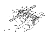
図面の図1,2,並びに3において、気密性のある端子アッセンブリ10が、ほぼ平らな底壁14と、外方へと押し広げられたリム18を有している側壁16とを備えたほぼカップ形状の本体部分12を有している。この本体部分12の底壁14は、皿状側部(dish-side)の内面22と、外面24と、複数の開口部26とを有している。これら開口部26は、各々が、内壁面30と、皿状側部の自由エッジ32と、外径面34を有している環状リップ28とによって規定されている。
The following description of the preferred embodiment is merely an example in nature and is not intended to limit the invention, its application, and use. In FIGS. The
外端部38と内端部40とを有している導電性の端子ピン36が、従来の端子タブ(図示されず)によって装着されることができる。導電性の端子ピン36は、前記本体部分12中に直接モールド成形され、かつ本体部分12と端子ピン36とに取着されている誘電体のプラスチック樹脂材料44によって、前記開口部26中にシールされている。モールド成形によって、プラスチック樹脂44は、端子ピン36を介してアッセンブリ10を貫通する漏れを防止するように、気密性のハーメチックシールであるシール46を、端子ピン36と本体部分12との間に形成する。
A
好ましい実施形態において、前記プラスチック樹脂44は、前記底壁14の両側で、本体部分12中と、本体部分の周りとにモールド成形されている。従って、プラスチック樹脂44は、底壁14の皿状側部の内面22と外面24との両方をカバーして、本体部分12と機械的にインターロックされている。プラスチック樹脂は、端子アッセンブリ10の本体部分12の内側ならびに外側をカバーする誘電体の上面(oversurface)を与えている。さらに、プラスチック樹脂44は、また、所望に応じて、夫々の端子ピン36、並びに/若しくは本体部分12間に空気路を形成するように、本体部分12から端子ピンの外端部38へと突出している端子ピン36の一部に取着され、かつこの一部をカバーしているスリーブ部分47を有することができる。
In a preferred embodiment, the
前記本体部分12の皿状側部の内面22に、モールド成形された前記プラスチック樹脂44は、複数のネック部分48を形成している。これらネック部分の各々は、本体部分12の底壁14の開口部26を規定している環状リップ28を囲むように環状リップ近くに設けられている。各ネック部分48は、端子ピン36が、端子アッセンブリ10の本体部分12の皿状側部の内面22から突出している距離の約1/4ないし1/3ほど、ネック部分の夫々の端子ピン36に沿って内端部40へと延びている。誘電体の上面を与えることに加え、ネック部分48は、ハーメチックシール46の長さを延ばして、所定の位置に端子ピン36をより良く固定している。
The
各端子ピン36は、端子アッセンブリ10の本体部分12を貫通しているシャンク部分50を有している。前記プラスチック樹脂44は、ハーメチックシール46を形成して、端子ピン36を端子アッセンブリ10の本体部分12に取着させるように、前記内壁30と端子ピン36のシャンク部分50との間のスペースを充填している。端子ピン36のシャンク部分50を含む部分には、端子アッセンブリ10の本体部分12内に位置されるようにシール46によって囲まれているヒューズセクション52が設けられている。このヒューズセクション52は、端子ピン36の残りの部分から径方向に下がっているネック部分(necked down diameter)を有している。ヒューズセクション52は、予め設定された電流容量を超える電流で切れるようになっている。代わりに、端子ピン36は、Honkompらにより米国特許第5,017,740号に開示され、かつ参照により開示文書に組み込まれる端子ピンのように、端子アッセンブリ10の本体部分12の外側にあるヒューズ部で構成されることができる。
Each
ハーメチックシール46を形成するためにモールド成形された前記プラスチック樹脂44は、気密性のある端子アッセンブリが利用される適用ならびに動作環境のために必要とされる適切な電気並びに機械的性質を有していなければならない。代表的な最小の工業材料の必要条件は、以下の通りであり得る。

本発明の使用に適したプラスチック樹脂は、開示されているようなハーメチックシール46と誘電体の上面とを与えることができるモールド成形可能なプラスチック樹脂である。このようなモールド成形可能なプラスチック樹脂は、商品名RYTONで知られているポリフェニレンスルフィド(PPS)である。さらに、必要な電気ならびに機械的性質を有し、かつ液晶性ポリマー化合物(LCPs)を有する他のモールド成形可能なプラスチック樹脂が、使用されることもできる。このような材料の一例が、商品名Zenite(登録商標)でデュポン社から市販されている。
Plastic resins suitable for use in the present invention are moldable plastic resins that can provide a
さらに、完全なハーメチックシールが必ずしも必要ではなく、気密とはいえない、半気密シール、もしくは、さらに、弱い気密シールが必要とされる、動作もしくは性能面の要求を持たない本発明の端子アッセンブリ10の適用例があり得る。本発明の端子アッセンブリ10が、このような適用例での使用に用いられ得ることは、十分に考えられる。このような適用例での本発明の使用に適し得るさらなるモールド成形可能なプラスチック樹脂は、ポリプロピレン、熱可塑性ポリオレフィン、並びにBakelite(登録商標)のようなポリ塩化ビニルである。
In addition, a complete hermetic seal is not necessarily required and is not hermetic, requires a semi-hermetic seal, or even a weaker hermetic seal, and does not have operational or performance requirements. There may be application examples. It is fully contemplated that the
前記端子ピン36は、固体の銅もしくは鋼のような導電性の材料で製造されている。代わりに、高導電性を有し、プラスチック樹脂44に関連した十分な気密性のある取着の特徴を有し、二種の金属からなる銅の心線が使用されることもできる。
The
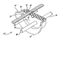
図4並びに図5には、本発明の気密性のある端子アッセンブリ10’の第2の実施形態が示されている。図に示された第1の実施形態と第2の実施形態との両方に共通する部材ならびに特徴は、同様の参照符号で示されている。 4 and 5 show a second embodiment of the hermetic terminal assembly 10 'of the present invention. Members and features common to both the first and second embodiments shown in the figures are indicated by like reference numerals.
端子ピン36’のシャンク部分50’には、表面の粗さが増された(increased surface roughness)の加工面56を有したセクション54が設けられている。このような面は、端子ピン36’をサンダー仕上げ、即ちグリッドブラストのような機械的手段によって、若しくは、他の同様な処理、即ち科学的手段によって達せられることができる。加工面56は、面の面積を大きくするために端子ピン36’に設けられている。この広い面全体に渡って、プラスチック樹脂44’が、端子ピン36’に接触し、この端子ピンに機械的に係合され、かくしてシール46’の気密性を改良している。図4ならびに図5に示されていないが、端子ピン36’は、また、上述されたものに類似したヒューズセクションを組み込むことができる。このようなヒューズセクションは、また、加工面56を有することができる。
The shank portion 50 'of the terminal pin 36' is provided with a
さらに、上述されたように、プラスチック樹脂44’は、所望に応じて、夫々の端子ピン36’、並びに/若しくは本体部分12’間に空気路を形成するように、端子ピン36’の突出外端部38’の一部をカバーすることができる。 In addition, as described above, the plastic resin 44 'may be formed on the terminal pins 36' so as to form an air passage between the respective terminal pins 36 'and / or the body portion 12' as desired. A portion of the end 38 'can be covered.
本発明の気密性のある端子アッセンブリ10’’の更なる他の実施形態が、図6並びに図7に示されている。この第3の実施形態において、端子アッセンブリ10’’は、外方へと押し広げられたリム18’’を有した側壁16’’を備えているほぼカップ形状の本体部分12”を有している。この本体部分は、ほぼ連続した閉成状態の底壁を有していないが、代わりに、両端部のリム18’’のところで側壁16’’から内方へと延びている末梢リップ58のみを有している。プラスチック樹脂44’’が、この末梢リップ58を囲むように末梢リップにモールド成形され、従って、本体部分12”と機械的にインターロックされている。上述した実施形態と同様に、プラスチック樹脂44”は、また、所望に応じて、夫々の端子ピン36’、並びに/若しくは本体部分12’間に空気路を形成するように、端子ピン36”の突出外端部38”の一部を覆うようにモールド成形されることができる。
Yet another embodiment of the hermetic terminal assembly 10 '' of the present invention is shown in FIGS. In this third embodiment, the
本発明の第3の実施形態の端子ピン36”は、また、上述した端子ピン36,36’と異なることができる。図6に示されたように、端子ピン36”のシャンク部分50”は、ねじ留め面(threaded surface)56’を形成しているセクション54’である。上述したものと同様に、このねじ留め面56’は、端子ピン36”の面エリアを広げるために端子ピン36”に設けられている。この面エリアを覆うように、プラスチック樹脂44”は、端子ピン36”に接触、並びに機械的に係合されることができる。係合によって広げられたエリアは、端子ピン36”とプラスチック樹脂44”との間の取着力を高め、かくして、シール46”の気密性を向上させる。再び、端子ピン36”は、また、上の図1並びに図2に関して開示されたものと類似したヒューズセクションを組み込むことができる。このようなヒューズセクションは、また、ねじ留め面56’を有することができる。
The
もちろん、本体部分12,12’,12”、若しくは端子ピン36,36’,36”の特徴は、本発明の意図に関連した気密性のある端子アッセンブリを形成する様々な方法に組合わされることができる。
Of course, the features of the
本発明は、好ましい形態で開示並びに説明されているが、添付された請求項に説明されているように、本発明の精神ならびに範囲から逸脱することなく変更可能であることは理解される。 While the invention has been disclosed and described in preferred forms, it is to be understood that modifications can be made without departing from the spirit and scope of the invention as set forth in the appended claims.
Claims (31)
前記底部の開口部を通って長手方向に延びている導電性のピンと、
前記金属本体の底部の前記内面と前記開口部との各々の部分を少なくともカバーしている誘電体のプラスチック樹脂とを具備し、このプラスチック樹脂は、前記金属本体と前記ピンとの両方に取着され、また、前記ピンと底部の、このピンが中を延びている前記開口部との間に、少なくとも約1×10⁻⁶atm cc/secのシールを与えている、端子アッセンブリ。 A metal body having a bottom with an inner surface, an outer surface and at least one opening;
A conductive pin extending longitudinally through the bottom opening;
A dielectric plastic resin covering at least each of the inner surface and the opening of the bottom of the metal body, the plastic resin being attached to both the metal body and the pin. And a terminal assembly providing a seal of at least about 1 × 10 −6 atm cc / sec between the pin and the bottom of the opening through which the pin extends.
前記開口部を通って長手方向に延びている導電性のピンと、
このピンを受け、前記内面の一部を少なくともカバーし、そして前記壁の一部を少なくとも囲んでいる、予め成形された誘電体のリテイナーと、
前記本体と前記リテイナーと前記ピンとに取着され、かつこのピンと底部の、このピンが中を延びている前記開口部との間にシールを与えている誘電体のエポキシとを具備する、端子アッセンブリ。 A metal body having a bottom with an inner surface, an outer surface, and at least one opening with a wall;
A conductive pin extending longitudinally through the opening;
A pre-formed dielectric retainer that receives the pin, covers at least a portion of the inner surface, and surrounds at least a portion of the wall;
A terminal assembly comprising a dielectric epoxy attached to the body, the retainer and the pin and providing a seal between the pin and the bottom and the opening through which the pin extends. .
前記開口部を通って長手方向に延びている導電性のピンと、
前記金属本体の前記内面と、前記外面と、底部の前記開口部を貫通しているピンとに取着され、かつ前記ピンと、前記開口部と、開口部の前記壁との間に、少なくとも約1×10⁻⁶atm cc/secのシールを与えている誘電体のエポキシとを具備している、気密性のある端子アッセンブリ。 A metal body comprising a bottom having an inner surface, an outer surface, and at least one opening with a wall;
A conductive pin extending longitudinally through the opening;
At least about 1 between the inner surface of the metal body, the outer surface, and a pin passing through the opening at the bottom, and between the pin, the opening, and the wall of the opening. A hermetic terminal assembly comprising a dielectric epoxy providing a seal of x10-6 atm cc / sec.
これらピンとリテイナーとを覆うように第1のエポキシ・リングを位置付けることと、
前記ピンと前記リテイナーと前記第1のエポキシ・リングとを覆うように、ピンホールを有している金属本体を位置付けることと、
前記ピンと前記金属本体とを覆うように第2のエポキシ・リングを位置付けることと、
前記ピンと金属本体の前記ピンホールとの間にシールを与えるように、前記第1のエポキシ・リングと前記第2のエポキシ・リングとを硬化させることとを具備している、気密性のある端子アッセンブリを形成するための方法。 Positioning the terminal pin in the retainer;
Positioning the first epoxy ring over the pins and retainer;
Positioning a metal body having a pinhole so as to cover the pin, the retainer and the first epoxy ring;
Positioning a second epoxy ring so as to cover the pin and the metal body;
An airtight terminal comprising: curing the first epoxy ring and the second epoxy ring to provide a seal between the pin and the pinhole in the metal body. A method for forming an assembly.
この端子ピンを覆うように第1のエポキシ・リングを位置付けることと、
前記ピンと前記第1のエポキシ・リングとを覆うように、ピンホールを有している金属本体を位置付けることと、
前記ピンと前記金属本体とを覆うように、第2のエポキシ・リングを位置付けることと、
前記ピンと金属本体の前記ピンホールとの間にシールを与えるように、前記第1のエポキシ・リングと前記第2のエポキシ・リングとを硬化させることとを具備している、気密性のある端子アッセンブリを形成するための方法。 Giving terminal pins,
Positioning the first epoxy ring over the terminal pin;
Positioning a metal body having a pinhole so as to cover the pin and the first epoxy ring;
Positioning a second epoxy ring so as to cover the pin and the metal body;
An airtight terminal comprising: curing the first epoxy ring and the second epoxy ring to provide a seal between the pin and the pinhole in the metal body. A method for forming an assembly.
Applications Claiming Priority (2)
| Application Number | Priority Date | Filing Date | Title |
|---|---|---|---|
| US10/633,962 US6921297B2 (en) | 2002-02-08 | 2003-08-04 | Hermetic terminal assembly and associated method of manufacture |
| PCT/US2004/023996 WO2005017925A1 (en) | 2003-08-04 | 2004-07-26 | Hermetic terminal assembly |
Publications (2)
| Publication Number | Publication Date |
|---|---|
| JP2007501499A true JP2007501499A (en) | 2007-01-25 |
| JP2007501499A5 JP2007501499A5 (en) | 2007-09-13 |
Family
ID=34193527
Family Applications (1)
| Application Number | Title | Priority Date | Filing Date |
|---|---|---|---|
| JP2006522594A Pending JP2007501499A (en) | 2003-08-04 | 2004-07-26 | Airtight terminal assembly |
Country Status (5)
| Country | Link |
|---|---|
| US (1) | US6921297B2 (en) |
| EP (1) | EP1654741A1 (en) |
| JP (1) | JP2007501499A (en) |
| CN (1) | CN2914267Y (en) |
| WO (1) | WO2005017925A1 (en) |
Cited By (2)
| Publication number | Priority date | Publication date | Assignee | Title |
|---|---|---|---|---|
| JP2015528631A (en) * | 2012-08-10 | 2015-09-28 | エマソン エレクトリック コー. | Hermetic terminal with pin separation structure |
| JP2019106363A (en) * | 2017-11-29 | 2019-06-27 | ショット アクチエンゲゼルシャフトSchott AG | Feedthrough with flat conductor |
Families Citing this family (32)
| Publication number | Priority date | Publication date | Assignee | Title |
|---|---|---|---|---|
| US7186127B2 (en) * | 2004-06-25 | 2007-03-06 | John Mezzalingua Associates, Inc. | Nut seal assembly for coaxial connector |
| US7500874B2 (en) * | 2004-06-25 | 2009-03-10 | John Mezzalingua Associates, Inc. | Nut seal assembly for coaxial cable system components |
| US7780722B2 (en) * | 2005-02-07 | 2010-08-24 | Boston Scientific Scimed, Inc. | Venous valve apparatus, system, and method |
| US7718899B2 (en) * | 2007-06-25 | 2010-05-18 | Harald Benestad | High pressure, high voltage penetrator assembly for subsea use |
| US20110083897A1 (en) * | 2008-05-19 | 2011-04-14 | Dieter Paterek | Electric power terminal feed-through |
| GB2464622B (en) * | 2008-09-18 | 2010-10-20 | Controlled Power Technologies | A power terminal in an intergrated starter generator |
| US8092044B1 (en) | 2008-11-21 | 2012-01-10 | Tomar Electronics, Inc. | LED light assembly and related methods |
| CN101430939B (en) * | 2008-12-08 | 2011-11-16 | 中国核动力研究设计院 | Electric penetration piece with radiation shielding structure |
| CN102334395A (en) * | 2009-02-25 | 2012-01-25 | 3M创新有限公司 | Article with gasket having moisture transmission resistivity and method |
| US7959454B2 (en) * | 2009-07-23 | 2011-06-14 | Teledyne Odi, Inc. | Wet mate connector |
| JP5615919B2 (en) * | 2009-08-05 | 2014-10-29 | テレダイン インストゥルメンツ、インク.Teledyne Instruments,Inc. | Electrical penetrator assembly |
| US8968018B2 (en) | 2009-08-05 | 2015-03-03 | Teledyne Instruments, Inc. | Electrical penetrator assembly |
| US7997931B2 (en) * | 2009-12-11 | 2011-08-16 | Aerovironment, Inc. | Waterproof electrical connector and system |
| DE102011001985C5 (en) * | 2011-04-12 | 2016-11-03 | R. Stahl Schaltgeräte GmbH | Implementation arrangement with high security |
| JP2012228974A (en) * | 2011-04-27 | 2012-11-22 | Toyota Motor Corp | Power unit |
| CN103001028B (en) * | 2011-09-08 | 2015-07-22 | 泰科电子(上海)有限公司 | Electric connector and manufacturing method thereof |
| CN103296495A (en) * | 2012-02-23 | 2013-09-11 | 艾默生电气公司 | Sealed power source feed-through terminal plate component |
| CN103078236B (en) * | 2012-12-18 | 2015-07-01 | 惠州市嘉泰电气有限公司 | Assembly fixture of compressor connection terminal |
| WO2014198329A1 (en) * | 2013-06-14 | 2014-12-18 | Abb Technology Ltd | Terminal bushing sealing element |
| CN103400731B (en) * | 2013-07-18 | 2015-09-09 | 国家电网公司 | A kind of boxlike dustproof and waterproof fuse |
| CN103441345A (en) * | 2013-07-30 | 2013-12-11 | 张家港市格致电器制造有限公司 | Sealing terminal board |
| US9559459B2 (en) * | 2013-10-18 | 2017-01-31 | Woodhead Industries, Inc. | Push-lock electrical connector |
| US20150171543A1 (en) * | 2013-12-13 | 2015-06-18 | General Electric Company | Sealed electrical connector assembly |
| DE102016209134B4 (en) * | 2016-05-25 | 2023-05-17 | Siemens Aktiengesellschaft | Thermally conductive ceramic bushing for switchgear |
| EP3252894A1 (en) * | 2016-05-30 | 2017-12-06 | Siemens Aktiengesellschaft | Penetrator device for high pressure application |
| US9692193B1 (en) * | 2016-07-28 | 2017-06-27 | Ge Aviation Systems, Llc | Connector having a plate seal and a conductor seal |
| CN107871947B (en) * | 2016-09-27 | 2024-03-26 | 泰科电子(上海)有限公司 | Connector, electrical connector, connection terminal assembly, and method for manufacturing connector |
| US10700502B2 (en) * | 2016-11-02 | 2020-06-30 | RPH Intellectual Holdings, LLC | Wall penetration panel |
| USD832795S1 (en) | 2017-01-17 | 2018-11-06 | Schott Japan Corporation | Hermetic terminal |
| USD832794S1 (en) | 2017-01-17 | 2018-11-06 | Schott Japan Corporation | Hermetic terminal |
| CN107265576B (en) * | 2017-07-19 | 2024-03-15 | 浙江安耐杰科技股份有限公司 | Conductive terminal of electro-adsorption desalting module |
| US20210159470A1 (en) * | 2019-11-27 | 2021-05-27 | Pacesetter, Inc. | Batteries with composite header construction |
Citations (4)
| Publication number | Priority date | Publication date | Assignee | Title |
|---|---|---|---|---|
| US3770878A (en) * | 1971-12-06 | 1973-11-06 | Terminals Inc | Hermetically sealed electrical terminal |
| JPS5022279A (en) * | 1973-06-13 | 1975-03-10 | ||
| JPS5472639U (en) * | 1977-11-01 | 1979-05-23 | ||
| JP2005517267A (en) * | 2002-02-08 | 2005-06-09 | エマーソン エレクトリック カンパニー | Sealed terminal parts |
Family Cites Families (17)
| Publication number | Priority date | Publication date | Assignee | Title |
|---|---|---|---|---|
| US3160460A (en) | 1962-01-17 | 1964-12-08 | Fusite Corp | Terminal assembly having conductor pins and connector block |
| US3388368A (en) | 1967-06-09 | 1968-06-11 | Westinghouse Electric Corp | Electrical terminal assembly and method of making same |
| US3605076A (en) | 1969-08-21 | 1971-09-14 | Us Terminals Inc | Hermetically sealed terminal construction |
| US3681517A (en) | 1969-12-22 | 1972-08-01 | Microdot Inc | Insulators for multiple-conductor connectors |
| US3721948A (en) | 1972-03-02 | 1973-03-20 | Gen Electric | Terminal assembly |
| US3775547A (en) | 1972-10-12 | 1973-11-27 | Westinghouse Electric Corp | Cast epoxy bushing having a weldable flange |
| US4296275A (en) | 1980-06-09 | 1981-10-20 | Emerson Electric Co. | Hermetic refrigeration terminal |
| US4356469A (en) | 1980-11-20 | 1982-10-26 | Hilliard Dozier | Electrical terminal with thermal interrupter |
| US4480151A (en) | 1982-07-19 | 1984-10-30 | Hilliard Dozier | Temperature stable hermetically sealed terminal |
| US4666228A (en) | 1983-09-28 | 1987-05-19 | Pave Technology Co. | Hermetic connector and method |
| US4652074A (en) | 1985-05-03 | 1987-03-24 | Kings Electronics Co., Inc. | Co-axial isolated ground bulkhead receptacle |
| US4913673A (en) * | 1988-07-29 | 1990-04-03 | Amp Incorporated | Hermetically sealed connector |
| US4921452A (en) | 1988-08-22 | 1990-05-01 | Hilliard Dozier | Breakaway hermetically sealed electrical terminal |
| CA2000711C (en) | 1988-10-14 | 1994-10-25 | Shoji Seike | Optical fiber composite insulator and method of producing the same |
| US4984973A (en) | 1990-03-21 | 1991-01-15 | Tecumseh Products Company | Hermetic motor compressor unit having a hermetic terminal with electrically insulating anti-tracking cap |
| US5344337A (en) | 1992-02-27 | 1994-09-06 | Halliburton Logging Services | Electrical connector with rubber boot seal |
| US6509525B2 (en) | 1998-11-07 | 2003-01-21 | Emerson Electric Co. | Hermetic terminal assembly |
-
2003
- 2003-08-04 US US10/633,962 patent/US6921297B2/en not_active Expired - Lifetime
-
2004
- 2004-07-26 WO PCT/US2004/023996 patent/WO2005017925A1/en active Application Filing
- 2004-07-26 EP EP04779175A patent/EP1654741A1/en not_active Withdrawn
- 2004-07-26 CN CNU2004900000209U patent/CN2914267Y/en not_active Expired - Lifetime
- 2004-07-26 JP JP2006522594A patent/JP2007501499A/en active Pending
Patent Citations (4)
| Publication number | Priority date | Publication date | Assignee | Title |
|---|---|---|---|---|
| US3770878A (en) * | 1971-12-06 | 1973-11-06 | Terminals Inc | Hermetically sealed electrical terminal |
| JPS5022279A (en) * | 1973-06-13 | 1975-03-10 | ||
| JPS5472639U (en) * | 1977-11-01 | 1979-05-23 | ||
| JP2005517267A (en) * | 2002-02-08 | 2005-06-09 | エマーソン エレクトリック カンパニー | Sealed terminal parts |
Cited By (2)
| Publication number | Priority date | Publication date | Assignee | Title |
|---|---|---|---|---|
| JP2015528631A (en) * | 2012-08-10 | 2015-09-28 | エマソン エレクトリック コー. | Hermetic terminal with pin separation structure |
| JP2019106363A (en) * | 2017-11-29 | 2019-06-27 | ショット アクチエンゲゼルシャフトSchott AG | Feedthrough with flat conductor |
Also Published As
| Publication number | Publication date |
|---|---|
| CN2914267Y (en) | 2007-06-20 |
| WO2005017925A1 (en) | 2005-02-24 |
| EP1654741A1 (en) | 2006-05-10 |
| US6921297B2 (en) | 2005-07-26 |
| US20040029443A1 (en) | 2004-02-12 |
Similar Documents
| Publication | Publication Date | Title |
|---|---|---|
| JP2007501499A (en) | Airtight terminal assembly | |
| JP2007501499A5 (en) | ||
| US6632104B2 (en) | Hermetic terminal assembly | |
| US8794999B2 (en) | Hermetic terminal having pin-isolating feature | |
| US6107566A (en) | Hermetic terminal structure | |
| US9673577B2 (en) | Power plug device and the manufacturing method thereof | |
| US20030119373A1 (en) | Connector block having at least one protrusion, for a terminal assembly | |
| WO1995010857A1 (en) | A connection device for the poles of electric accumulators | |
| US6305989B1 (en) | Connector block for a terminal assembly | |
| JP6715517B2 (en) | Capacitor | |
| US6433276B1 (en) | Surface mount feedthrough | |
| US10957490B2 (en) | Electronic unit | |
| JP2005188517A (en) | Electric component protecting device | |
| CN111133636B (en) | Assembly body | |
| JP2002005019A (en) | Device for protecting parts of electric equipment | |
| JP2013254659A (en) | Waterproofing push button switch member | |
| JP2007250805A (en) | Surface-mounting airtight terminal | |
| CN111029314A (en) | Semiconductor device with a plurality of semiconductor chips | |
| JPS6314441B2 (en) | ||
| CN109285696A (en) | The lid latching member of Wound capacitor for that can be arranged in cup | |
| CN211455988U (en) | Hermetic terminal and compressor of in-vehicle air conditioner | |
| JPS6321083Y2 (en) | ||
| JPH02115580A (en) | Protecting device for electrical equipment | |
| US7091582B2 (en) | Electronic package with snap-on perimeter wall | |
| IT202100011345A1 (en) | Reference electrode for monitoring the cathodic protection of metallic structures, in particular underground and/or submarine structures |
Legal Events
| Date | Code | Title | Description |
|---|---|---|---|
| A521 | Request for written amendment filed |
Free format text: JAPANESE INTERMEDIATE CODE: A523 Effective date: 20070726 |
|
| A621 | Written request for application examination |
Free format text: JAPANESE INTERMEDIATE CODE: A621 Effective date: 20070726 |
|
| A131 | Notification of reasons for refusal |
Free format text: JAPANESE INTERMEDIATE CODE: A131 Effective date: 20091222 |
|
| A02 | Decision of refusal |
Free format text: JAPANESE INTERMEDIATE CODE: A02 Effective date: 20100713 |