JP2007320847A - Core-shell ceramic particulate and method of making - Google Patents
Core-shell ceramic particulate and method of making Download PDFInfo
- Publication number
- JP2007320847A JP2007320847A JP2007141333A JP2007141333A JP2007320847A JP 2007320847 A JP2007320847 A JP 2007320847A JP 2007141333 A JP2007141333 A JP 2007141333A JP 2007141333 A JP2007141333 A JP 2007141333A JP 2007320847 A JP2007320847 A JP 2007320847A
- Authority
- JP
- Japan
- Prior art keywords
- core
- shell
- pores
- tertiary
- particulate
- Prior art date
- Legal status (The legal status is an assumption and is not a legal conclusion. Google has not performed a legal analysis and makes no representation as to the accuracy of the status listed.)
- Pending
Links
Images


Classifications
-
- C—CHEMISTRY; METALLURGY
- C04—CEMENTS; CONCRETE; ARTIFICIAL STONE; CERAMICS; REFRACTORIES
- C04B—LIME, MAGNESIA; SLAG; CEMENTS; COMPOSITIONS THEREOF, e.g. MORTARS, CONCRETE OR LIKE BUILDING MATERIALS; ARTIFICIAL STONE; CERAMICS; REFRACTORIES; TREATMENT OF NATURAL STONE
- C04B38/00—Porous mortars, concrete, artificial stone or ceramic ware; Preparation thereof
- C04B38/0051—Porous mortars, concrete, artificial stone or ceramic ware; Preparation thereof characterised by the pore size, pore shape or kind of porosity
- C04B38/0064—Multimodal pore size distribution
-
- B—PERFORMING OPERATIONS; TRANSPORTING
- B01—PHYSICAL OR CHEMICAL PROCESSES OR APPARATUS IN GENERAL
- B01D—SEPARATION
- B01D69/00—Semi-permeable membranes for separation processes or apparatus characterised by their form, structure or properties; Manufacturing processes specially adapted therefor
- B01D69/02—Semi-permeable membranes for separation processes or apparatus characterised by their form, structure or properties; Manufacturing processes specially adapted therefor characterised by their properties
-
- B—PERFORMING OPERATIONS; TRANSPORTING
- B01—PHYSICAL OR CHEMICAL PROCESSES OR APPARATUS IN GENERAL
- B01D—SEPARATION
- B01D71/00—Semi-permeable membranes for separation processes or apparatus characterised by the material; Manufacturing processes specially adapted therefor
- B01D71/02—Inorganic material
- B01D71/024—Oxides
-
- C—CHEMISTRY; METALLURGY
- C04—CEMENTS; CONCRETE; ARTIFICIAL STONE; CERAMICS; REFRACTORIES
- C04B—LIME, MAGNESIA; SLAG; CEMENTS; COMPOSITIONS THEREOF, e.g. MORTARS, CONCRETE OR LIKE BUILDING MATERIALS; ARTIFICIAL STONE; CERAMICS; REFRACTORIES; TREATMENT OF NATURAL STONE
- C04B35/00—Shaped ceramic products characterised by their composition; Ceramics compositions; Processing powders of inorganic compounds preparatory to the manufacturing of ceramic products
- C04B35/622—Forming processes; Processing powders of inorganic compounds preparatory to the manufacturing of ceramic products
- C04B35/626—Preparing or treating the powders individually or as batches ; preparing or treating macroscopic reinforcing agents for ceramic products, e.g. fibres; mechanical aspects section B
- C04B35/62605—Treating the starting powders individually or as mixtures
- C04B35/62645—Thermal treatment of powders or mixtures thereof other than sintering
- C04B35/62665—Flame, plasma or melting treatment
-
- C—CHEMISTRY; METALLURGY
- C04—CEMENTS; CONCRETE; ARTIFICIAL STONE; CERAMICS; REFRACTORIES
- C04B—LIME, MAGNESIA; SLAG; CEMENTS; COMPOSITIONS THEREOF, e.g. MORTARS, CONCRETE OR LIKE BUILDING MATERIALS; ARTIFICIAL STONE; CERAMICS; REFRACTORIES; TREATMENT OF NATURAL STONE
- C04B35/00—Shaped ceramic products characterised by their composition; Ceramics compositions; Processing powders of inorganic compounds preparatory to the manufacturing of ceramic products
- C04B35/622—Forming processes; Processing powders of inorganic compounds preparatory to the manufacturing of ceramic products
- C04B35/626—Preparing or treating the powders individually or as batches ; preparing or treating macroscopic reinforcing agents for ceramic products, e.g. fibres; mechanical aspects section B
- C04B35/628—Coating the powders or the macroscopic reinforcing agents
- C04B35/62802—Powder coating materials
- C04B35/62805—Oxide ceramics
- C04B35/62815—Rare earth metal oxides
-
- C—CHEMISTRY; METALLURGY
- C04—CEMENTS; CONCRETE; ARTIFICIAL STONE; CERAMICS; REFRACTORIES
- C04B—LIME, MAGNESIA; SLAG; CEMENTS; COMPOSITIONS THEREOF, e.g. MORTARS, CONCRETE OR LIKE BUILDING MATERIALS; ARTIFICIAL STONE; CERAMICS; REFRACTORIES; TREATMENT OF NATURAL STONE
- C04B35/00—Shaped ceramic products characterised by their composition; Ceramics compositions; Processing powders of inorganic compounds preparatory to the manufacturing of ceramic products
- C04B35/622—Forming processes; Processing powders of inorganic compounds preparatory to the manufacturing of ceramic products
- C04B35/626—Preparing or treating the powders individually or as batches ; preparing or treating macroscopic reinforcing agents for ceramic products, e.g. fibres; mechanical aspects section B
- C04B35/628—Coating the powders or the macroscopic reinforcing agents
- C04B35/62802—Powder coating materials
- C04B35/62805—Oxide ceramics
- C04B35/62826—Iron group metal oxides
-
- C—CHEMISTRY; METALLURGY
- C04—CEMENTS; CONCRETE; ARTIFICIAL STONE; CERAMICS; REFRACTORIES
- C04B—LIME, MAGNESIA; SLAG; CEMENTS; COMPOSITIONS THEREOF, e.g. MORTARS, CONCRETE OR LIKE BUILDING MATERIALS; ARTIFICIAL STONE; CERAMICS; REFRACTORIES; TREATMENT OF NATURAL STONE
- C04B35/00—Shaped ceramic products characterised by their composition; Ceramics compositions; Processing powders of inorganic compounds preparatory to the manufacturing of ceramic products
- C04B35/622—Forming processes; Processing powders of inorganic compounds preparatory to the manufacturing of ceramic products
- C04B35/626—Preparing or treating the powders individually or as batches ; preparing or treating macroscopic reinforcing agents for ceramic products, e.g. fibres; mechanical aspects section B
- C04B35/628—Coating the powders or the macroscopic reinforcing agents
- C04B35/62886—Coating the powders or the macroscopic reinforcing agents by wet chemical techniques
-
- C—CHEMISTRY; METALLURGY
- C04—CEMENTS; CONCRETE; ARTIFICIAL STONE; CERAMICS; REFRACTORIES
- C04B—LIME, MAGNESIA; SLAG; CEMENTS; COMPOSITIONS THEREOF, e.g. MORTARS, CONCRETE OR LIKE BUILDING MATERIALS; ARTIFICIAL STONE; CERAMICS; REFRACTORIES; TREATMENT OF NATURAL STONE
- C04B35/00—Shaped ceramic products characterised by their composition; Ceramics compositions; Processing powders of inorganic compounds preparatory to the manufacturing of ceramic products
- C04B35/622—Forming processes; Processing powders of inorganic compounds preparatory to the manufacturing of ceramic products
- C04B35/626—Preparing or treating the powders individually or as batches ; preparing or treating macroscopic reinforcing agents for ceramic products, e.g. fibres; mechanical aspects section B
- C04B35/628—Coating the powders or the macroscopic reinforcing agents
- C04B35/62894—Coating the powders or the macroscopic reinforcing agents with more than one coating layer
-
- C—CHEMISTRY; METALLURGY
- C04—CEMENTS; CONCRETE; ARTIFICIAL STONE; CERAMICS; REFRACTORIES
- C04B—LIME, MAGNESIA; SLAG; CEMENTS; COMPOSITIONS THEREOF, e.g. MORTARS, CONCRETE OR LIKE BUILDING MATERIALS; ARTIFICIAL STONE; CERAMICS; REFRACTORIES; TREATMENT OF NATURAL STONE
- C04B35/00—Shaped ceramic products characterised by their composition; Ceramics compositions; Processing powders of inorganic compounds preparatory to the manufacturing of ceramic products
- C04B35/622—Forming processes; Processing powders of inorganic compounds preparatory to the manufacturing of ceramic products
- C04B35/626—Preparing or treating the powders individually or as batches ; preparing or treating macroscopic reinforcing agents for ceramic products, e.g. fibres; mechanical aspects section B
- C04B35/628—Coating the powders or the macroscopic reinforcing agents
- C04B35/62897—Coatings characterised by their thickness
-
- C—CHEMISTRY; METALLURGY
- C04—CEMENTS; CONCRETE; ARTIFICIAL STONE; CERAMICS; REFRACTORIES
- C04B—LIME, MAGNESIA; SLAG; CEMENTS; COMPOSITIONS THEREOF, e.g. MORTARS, CONCRETE OR LIKE BUILDING MATERIALS; ARTIFICIAL STONE; CERAMICS; REFRACTORIES; TREATMENT OF NATURAL STONE
- C04B38/00—Porous mortars, concrete, artificial stone or ceramic ware; Preparation thereof
- C04B38/009—Porous or hollow ceramic granular materials, e.g. microballoons
-
- H—ELECTRICITY
- H01—ELECTRIC ELEMENTS
- H01M—PROCESSES OR MEANS, e.g. BATTERIES, FOR THE DIRECT CONVERSION OF CHEMICAL ENERGY INTO ELECTRICAL ENERGY
- H01M4/00—Electrodes
- H01M4/86—Inert electrodes with catalytic activity, e.g. for fuel cells
- H01M4/90—Selection of catalytic material
- H01M4/9016—Oxides, hydroxides or oxygenated metallic salts
- H01M4/9025—Oxides specially used in fuel cell operating at high temperature, e.g. SOFC
-
- C—CHEMISTRY; METALLURGY
- C04—CEMENTS; CONCRETE; ARTIFICIAL STONE; CERAMICS; REFRACTORIES
- C04B—LIME, MAGNESIA; SLAG; CEMENTS; COMPOSITIONS THEREOF, e.g. MORTARS, CONCRETE OR LIKE BUILDING MATERIALS; ARTIFICIAL STONE; CERAMICS; REFRACTORIES; TREATMENT OF NATURAL STONE
- C04B2111/00—Mortars, concrete or artificial stone or mixtures to prepare them, characterised by specific function, property or use
- C04B2111/00474—Uses not provided for elsewhere in C04B2111/00
- C04B2111/00793—Uses not provided for elsewhere in C04B2111/00 as filters or diaphragms
-
- C—CHEMISTRY; METALLURGY
- C04—CEMENTS; CONCRETE; ARTIFICIAL STONE; CERAMICS; REFRACTORIES
- C04B—LIME, MAGNESIA; SLAG; CEMENTS; COMPOSITIONS THEREOF, e.g. MORTARS, CONCRETE OR LIKE BUILDING MATERIALS; ARTIFICIAL STONE; CERAMICS; REFRACTORIES; TREATMENT OF NATURAL STONE
- C04B2235/00—Aspects relating to ceramic starting mixtures or sintered ceramic products
- C04B2235/02—Composition of constituents of the starting material or of secondary phases of the final product
- C04B2235/30—Constituents and secondary phases not being of a fibrous nature
- C04B2235/32—Metal oxides, mixed metal oxides, or oxide-forming salts thereof, e.g. carbonates, nitrates, (oxy)hydroxides, chlorides
- C04B2235/3201—Alkali metal oxides or oxide-forming salts thereof
- C04B2235/3203—Lithium oxide or oxide-forming salts thereof
-
- C—CHEMISTRY; METALLURGY
- C04—CEMENTS; CONCRETE; ARTIFICIAL STONE; CERAMICS; REFRACTORIES
- C04B—LIME, MAGNESIA; SLAG; CEMENTS; COMPOSITIONS THEREOF, e.g. MORTARS, CONCRETE OR LIKE BUILDING MATERIALS; ARTIFICIAL STONE; CERAMICS; REFRACTORIES; TREATMENT OF NATURAL STONE
- C04B2235/00—Aspects relating to ceramic starting mixtures or sintered ceramic products
- C04B2235/02—Composition of constituents of the starting material or of secondary phases of the final product
- C04B2235/30—Constituents and secondary phases not being of a fibrous nature
- C04B2235/32—Metal oxides, mixed metal oxides, or oxide-forming salts thereof, e.g. carbonates, nitrates, (oxy)hydroxides, chlorides
- C04B2235/3224—Rare earth oxide or oxide forming salts thereof, e.g. scandium oxide
- C04B2235/3225—Yttrium oxide or oxide-forming salts thereof
-
- C—CHEMISTRY; METALLURGY
- C04—CEMENTS; CONCRETE; ARTIFICIAL STONE; CERAMICS; REFRACTORIES
- C04B—LIME, MAGNESIA; SLAG; CEMENTS; COMPOSITIONS THEREOF, e.g. MORTARS, CONCRETE OR LIKE BUILDING MATERIALS; ARTIFICIAL STONE; CERAMICS; REFRACTORIES; TREATMENT OF NATURAL STONE
- C04B2235/00—Aspects relating to ceramic starting mixtures or sintered ceramic products
- C04B2235/02—Composition of constituents of the starting material or of secondary phases of the final product
- C04B2235/30—Constituents and secondary phases not being of a fibrous nature
- C04B2235/32—Metal oxides, mixed metal oxides, or oxide-forming salts thereof, e.g. carbonates, nitrates, (oxy)hydroxides, chlorides
- C04B2235/3224—Rare earth oxide or oxide forming salts thereof, e.g. scandium oxide
- C04B2235/3227—Lanthanum oxide or oxide-forming salts thereof
-
- C—CHEMISTRY; METALLURGY
- C04—CEMENTS; CONCRETE; ARTIFICIAL STONE; CERAMICS; REFRACTORIES
- C04B—LIME, MAGNESIA; SLAG; CEMENTS; COMPOSITIONS THEREOF, e.g. MORTARS, CONCRETE OR LIKE BUILDING MATERIALS; ARTIFICIAL STONE; CERAMICS; REFRACTORIES; TREATMENT OF NATURAL STONE
- C04B2235/00—Aspects relating to ceramic starting mixtures or sintered ceramic products
- C04B2235/02—Composition of constituents of the starting material or of secondary phases of the final product
- C04B2235/30—Constituents and secondary phases not being of a fibrous nature
- C04B2235/32—Metal oxides, mixed metal oxides, or oxide-forming salts thereof, e.g. carbonates, nitrates, (oxy)hydroxides, chlorides
- C04B2235/3231—Refractory metal oxides, their mixed metal oxides, or oxide-forming salts thereof
- C04B2235/3244—Zirconium oxides, zirconates, hafnium oxides, hafnates, or oxide-forming salts thereof
-
- C—CHEMISTRY; METALLURGY
- C04—CEMENTS; CONCRETE; ARTIFICIAL STONE; CERAMICS; REFRACTORIES
- C04B—LIME, MAGNESIA; SLAG; CEMENTS; COMPOSITIONS THEREOF, e.g. MORTARS, CONCRETE OR LIKE BUILDING MATERIALS; ARTIFICIAL STONE; CERAMICS; REFRACTORIES; TREATMENT OF NATURAL STONE
- C04B2235/00—Aspects relating to ceramic starting mixtures or sintered ceramic products
- C04B2235/02—Composition of constituents of the starting material or of secondary phases of the final product
- C04B2235/30—Constituents and secondary phases not being of a fibrous nature
- C04B2235/32—Metal oxides, mixed metal oxides, or oxide-forming salts thereof, e.g. carbonates, nitrates, (oxy)hydroxides, chlorides
- C04B2235/327—Iron group oxides, their mixed metal oxides, or oxide-forming salts thereof
- C04B2235/3272—Iron oxides or oxide forming salts thereof, e.g. hematite, magnetite
- C04B2235/3274—Ferrites
-
- C—CHEMISTRY; METALLURGY
- C04—CEMENTS; CONCRETE; ARTIFICIAL STONE; CERAMICS; REFRACTORIES
- C04B—LIME, MAGNESIA; SLAG; CEMENTS; COMPOSITIONS THEREOF, e.g. MORTARS, CONCRETE OR LIKE BUILDING MATERIALS; ARTIFICIAL STONE; CERAMICS; REFRACTORIES; TREATMENT OF NATURAL STONE
- C04B2235/00—Aspects relating to ceramic starting mixtures or sintered ceramic products
- C04B2235/02—Composition of constituents of the starting material or of secondary phases of the final product
- C04B2235/30—Constituents and secondary phases not being of a fibrous nature
- C04B2235/34—Non-metal oxides, non-metal mixed oxides, or salts thereof that form the non-metal oxides upon heating, e.g. carbonates, nitrates, (oxy)hydroxides, chlorides
- C04B2235/3409—Boron oxide, borates, boric acids, or oxide forming salts thereof, e.g. borax
-
- C—CHEMISTRY; METALLURGY
- C04—CEMENTS; CONCRETE; ARTIFICIAL STONE; CERAMICS; REFRACTORIES
- C04B—LIME, MAGNESIA; SLAG; CEMENTS; COMPOSITIONS THEREOF, e.g. MORTARS, CONCRETE OR LIKE BUILDING MATERIALS; ARTIFICIAL STONE; CERAMICS; REFRACTORIES; TREATMENT OF NATURAL STONE
- C04B2235/00—Aspects relating to ceramic starting mixtures or sintered ceramic products
- C04B2235/02—Composition of constituents of the starting material or of secondary phases of the final product
- C04B2235/50—Constituents or additives of the starting mixture chosen for their shape or used because of their shape or their physical appearance
- C04B2235/52—Constituents or additives characterised by their shapes
- C04B2235/528—Spheres
-
- C—CHEMISTRY; METALLURGY
- C04—CEMENTS; CONCRETE; ARTIFICIAL STONE; CERAMICS; REFRACTORIES
- C04B—LIME, MAGNESIA; SLAG; CEMENTS; COMPOSITIONS THEREOF, e.g. MORTARS, CONCRETE OR LIKE BUILDING MATERIALS; ARTIFICIAL STONE; CERAMICS; REFRACTORIES; TREATMENT OF NATURAL STONE
- C04B2235/00—Aspects relating to ceramic starting mixtures or sintered ceramic products
- C04B2235/02—Composition of constituents of the starting material or of secondary phases of the final product
- C04B2235/50—Constituents or additives of the starting mixture chosen for their shape or used because of their shape or their physical appearance
- C04B2235/54—Particle size related information
- C04B2235/5418—Particle size related information expressed by the size of the particles or aggregates thereof
- C04B2235/5436—Particle size related information expressed by the size of the particles or aggregates thereof micrometer sized, i.e. from 1 to 100 micron
-
- H—ELECTRICITY
- H01—ELECTRIC ELEMENTS
- H01M—PROCESSES OR MEANS, e.g. BATTERIES, FOR THE DIRECT CONVERSION OF CHEMICAL ENERGY INTO ELECTRICAL ENERGY
- H01M8/00—Fuel cells; Manufacture thereof
- H01M8/10—Fuel cells with solid electrolytes
- H01M8/12—Fuel cells with solid electrolytes operating at high temperature, e.g. with stabilised ZrO2 electrolyte
- H01M2008/1293—Fuel cells with solid oxide electrolytes
-
- Y—GENERAL TAGGING OF NEW TECHNOLOGICAL DEVELOPMENTS; GENERAL TAGGING OF CROSS-SECTIONAL TECHNOLOGIES SPANNING OVER SEVERAL SECTIONS OF THE IPC; TECHNICAL SUBJECTS COVERED BY FORMER USPC CROSS-REFERENCE ART COLLECTIONS [XRACs] AND DIGESTS
- Y02—TECHNOLOGIES OR APPLICATIONS FOR MITIGATION OR ADAPTATION AGAINST CLIMATE CHANGE
- Y02E—REDUCTION OF GREENHOUSE GAS [GHG] EMISSIONS, RELATED TO ENERGY GENERATION, TRANSMISSION OR DISTRIBUTION
- Y02E60/00—Enabling technologies; Technologies with a potential or indirect contribution to GHG emissions mitigation
- Y02E60/30—Hydrogen technology
- Y02E60/50—Fuel cells
-
- Y—GENERAL TAGGING OF NEW TECHNOLOGICAL DEVELOPMENTS; GENERAL TAGGING OF CROSS-SECTIONAL TECHNOLOGIES SPANNING OVER SEVERAL SECTIONS OF THE IPC; TECHNICAL SUBJECTS COVERED BY FORMER USPC CROSS-REFERENCE ART COLLECTIONS [XRACs] AND DIGESTS
- Y10—TECHNICAL SUBJECTS COVERED BY FORMER USPC
- Y10T—TECHNICAL SUBJECTS COVERED BY FORMER US CLASSIFICATION
- Y10T428/00—Stock material or miscellaneous articles
- Y10T428/29—Coated or structually defined flake, particle, cell, strand, strand portion, rod, filament, macroscopic fiber or mass thereof
- Y10T428/2982—Particulate matter [e.g., sphere, flake, etc.]
- Y10T428/2991—Coated
- Y10T428/2993—Silicic or refractory material containing [e.g., tungsten oxide, glass, cement, etc.]
- Y10T428/2995—Silane, siloxane or silicone coating
-
- Y—GENERAL TAGGING OF NEW TECHNOLOGICAL DEVELOPMENTS; GENERAL TAGGING OF CROSS-SECTIONAL TECHNOLOGIES SPANNING OVER SEVERAL SECTIONS OF THE IPC; TECHNICAL SUBJECTS COVERED BY FORMER USPC CROSS-REFERENCE ART COLLECTIONS [XRACs] AND DIGESTS
- Y10—TECHNICAL SUBJECTS COVERED BY FORMER USPC
- Y10T—TECHNICAL SUBJECTS COVERED BY FORMER US CLASSIFICATION
- Y10T428/00—Stock material or miscellaneous articles
- Y10T428/29—Coated or structually defined flake, particle, cell, strand, strand portion, rod, filament, macroscopic fiber or mass thereof
- Y10T428/2982—Particulate matter [e.g., sphere, flake, etc.]
- Y10T428/2991—Coated
- Y10T428/2993—Silicic or refractory material containing [e.g., tungsten oxide, glass, cement, etc.]
- Y10T428/2996—Glass particles or spheres
-
- Y—GENERAL TAGGING OF NEW TECHNOLOGICAL DEVELOPMENTS; GENERAL TAGGING OF CROSS-SECTIONAL TECHNOLOGIES SPANNING OVER SEVERAL SECTIONS OF THE IPC; TECHNICAL SUBJECTS COVERED BY FORMER USPC CROSS-REFERENCE ART COLLECTIONS [XRACs] AND DIGESTS
- Y10—TECHNICAL SUBJECTS COVERED BY FORMER USPC
- Y10T—TECHNICAL SUBJECTS COVERED BY FORMER US CLASSIFICATION
- Y10T428/00—Stock material or miscellaneous articles
- Y10T428/29—Coated or structually defined flake, particle, cell, strand, strand portion, rod, filament, macroscopic fiber or mass thereof
- Y10T428/2982—Particulate matter [e.g., sphere, flake, etc.]
- Y10T428/2991—Coated
- Y10T428/2998—Coated including synthetic resin or polymer
Landscapes
- Chemical & Material Sciences (AREA)
- Engineering & Computer Science (AREA)
- Ceramic Engineering (AREA)
- Manufacturing & Machinery (AREA)
- Materials Engineering (AREA)
- Structural Engineering (AREA)
- Organic Chemistry (AREA)
- Inorganic Chemistry (AREA)
- Chemical Kinetics & Catalysis (AREA)
- General Chemical & Material Sciences (AREA)
- Physics & Mathematics (AREA)
- Electrochemistry (AREA)
- Plasma & Fusion (AREA)
- Thermal Sciences (AREA)
- Separation Using Semi-Permeable Membranes (AREA)
- Compositions Of Oxide Ceramics (AREA)
- Inorganic Compounds Of Heavy Metals (AREA)
- Inert Electrodes (AREA)
Abstract
Description
本発明は、一般的にはコアシェルセラミック微粒子に関する。さらに詳しくは、本発明は高温で構造的及び機械的に安定なコアシェルセラミック微粒子に関する。本発明はまた、コアシェルセラミック微粒子の製造方法及びそれから製造される物品にも関する。 The present invention relates generally to core-shell ceramic particulates. More particularly, the present invention relates to core-shell ceramic particulates that are structurally and mechanically stable at high temperatures. The present invention also relates to a method for producing core-shell ceramic particulates and articles produced therefrom.
多孔質固体は、固体表面だけでなく材料の全体にわたって原子、イオン及び分子と相互作用する能力を有するので、科学的及び技術的に興味深いものである。多孔質構造体の増加した表面積は、イオン交換、吸着、感知及び触媒特性のような表面現象を伴う用途に対して明確な利点を与える。したがって、多孔質構造体は濾過、分離、触媒、検出及びセンサー用途で広く使用されてきた。多孔質構造体では、最終用途及び作業環境に応じて各種の有機及び無機材料が探求されてきた。特に高温及び高圧を伴う用途に関して短い応答時間、高い選択性及び長期安定性を示し得る材料に対する需要が増加している。セラミック材料は、熱的及び化学的安定性、良好な耐浸食性並びに高圧安定性という利点を有している。したがって、これらの用途の多くでセラミック多孔質構造体が広く使用されてきた。しかし、多孔質セラミック構造体を含む装置は、例えばガス分離アセンブリ又はセンサーアセンブリ中に存在し得る温度サイクルへの暴露に際してのゆがみ又は変形によって劣化することがある。高温作業に適した多孔質セラミック構造体の効率を向上させるための努力が続けられている。多大の努力にもかかわらず、大きい表面積及び良好な構造安定性を有する多孔質セラミック構造体に対するニーズが依然として存在する。
本発明は、階層的多孔質構造並びに高温での機械的及び構造的安定性を有するコアシェルセラミック微粒子を提供することで上記その他のニーズに応える。 The present invention addresses these and other needs by providing core-shell ceramic particulates having a hierarchical porous structure and mechanical and structural stability at high temperatures.
したがって、本発明の一態様はコアシェルセラミック微粒子を提供することである。かかるコアシェルセラミック微粒子は、複数の一次微粒子及び複数の一次細孔を含むコア微粒子構造体と、コア微粒子構造体を少なくとも部分的に囲繞するシェルとを含んでなる。一次微粒子の各々は複数の二次微粒子及び複数の二次細孔を含み、シェルは複数の三次微粒子及び複数の三次細孔を含む。 Accordingly, one aspect of the present invention is to provide core shell ceramic particulates. The core shell ceramic fine particles include a core fine particle structure including a plurality of primary fine particles and a plurality of primary pores, and a shell that at least partially surrounds the core fine particle structure. Each primary particle includes a plurality of secondary particles and a plurality of secondary pores, and the shell includes a plurality of tertiary particles and a plurality of tertiary pores.
本発明の第二の態様は、コアシェルセラミック微粒子の製造方法を提供する。かかる方法は、複数の一次微粒子及び複数の一次細孔を含むコア微粒子構造体であって、各一次微粒子が複数の二次微粒子及び複数の二次細孔を含むコア微粒子構造体を用意する段階と、コア微粒子構造体上に複数の三次微粒子及び複数の三次細孔を含むシェルを設ける段階とを含んでなる。 The second aspect of the present invention provides a method for producing core-shell ceramic fine particles. The method includes preparing a core fine particle structure including a plurality of primary fine particles and a plurality of primary pores, wherein each primary fine particle includes a plurality of secondary fine particles and a plurality of secondary pores. And providing a shell including a plurality of tertiary fine particles and a plurality of tertiary pores on the core fine particle structure.
別の態様では、本発明の実施形態は物品を提供する。かかる物品は複数のコアシェルセラミック微粒子を含んでなる。コアシェルセラミック微粒子は、複数の一次微粒子及び複数の一次細孔を含むコア微粒子構造体と、コア微粒子構造体を少なくとも部分的に囲繞するシェルとを含んでなる。一次微粒子の各々は複数の二次微粒子及び複数の二次細孔を含み、シェルは複数の三次微粒子及び複数の三次細孔を含む。 In another aspect, embodiments of the present invention provide an article. Such articles comprise a plurality of core shell ceramic particulates. The core-shell ceramic fine particles include a core fine particle structure including a plurality of primary fine particles and a plurality of primary pores, and a shell that at least partially surrounds the core fine particle structure. Each primary particle includes a plurality of secondary particles and a plurality of secondary pores, and the shell includes a plurality of tertiary particles and a plurality of tertiary pores.
本発明の上記その他の特徴、態様及び利点は、以下の詳細な説明とともに添付の図面を参照することによって理解を深めることができよう。図面全体を通じて、同じ符号は類似の構成部分を表している。 These and other features, aspects and advantages of the present invention may be better understood by reference to the accompanying drawings, taken in conjunction with the following detailed description. Throughout the drawings, the same reference numerals represent similar components.
以下の説明では、図面中の複数の図のすべてにわたり、同じ参照符号は類似の又は対応する構成部分を表している。また、「上部」、「下部」、「外方」、「内方」、「第一」、「第二」などの用語は便宜上の言葉であって、限定的な用語と解すべきでないことはもちろんである。さらに、本発明の特定の態様がある群の複数の構成要素の1以上又はこれらの組合せを含むか或いはそれからなるといわれる場合には、かかる態様がその群の構成要素のいずれかを単独で又はその群のいずれか他の構成要素と共に含むか或いはそれからなるものでもよいことはもちろんである。 In the following description, like reference characters designate like or corresponding parts throughout the several views of the drawings. In addition, terms such as “upper”, “lower”, “outer”, “inner”, “first”, “second” are words for convenience and should not be interpreted as restrictive terms. Of course. Further, where a particular aspect of the invention is said to include or consist of one or more of a group of components or a combination thereof, such aspect may be any of the group members alone or Of course, it may be included or consist of any other member of the group.
本発明を理解する目的のため、本明細書で使用する「マイクロ多孔質」という用語は2nm以下の細孔径を有する構造体を意味し、「メソ多孔質」という用語は2〜50nmの細孔径を有する構造体を意味し、「マクロ多孔質」という用語は50nm以上の細孔径を有する構造体を意味する。本明細書で使用する「細孔」とは、固体物質で占拠されていない、多孔質構造体中の空隙として理解すべきである。例えば、一次細孔は一次微粒子間の何もない領域であり、二次細孔は二次微粒子間の何もない領域であり、三次細孔は三次微粒子間の何もない領域である。したがって、細孔径及び細孔形状は一般に微粒子の粒径及び充填状態で決定される。くびれた粒子の場合、細孔サイズ及び形状は微粒子の粒径及び充填状態に加えてくびれの向き及び形状に依存する。 For purposes of understanding the present invention, the term “microporous” as used herein means a structure having a pore size of 2 nm or less, and the term “mesoporous” is a pore size of 2-50 nm. The term “macroporous” means a structure having a pore diameter of 50 nm or more. As used herein, “pores” should be understood as voids in a porous structure that are not occupied by a solid material. For example, the primary pore is a region where there is nothing between primary particles, the secondary pore is a region where there is nothing between secondary particles, and the tertiary pore is a region where there is nothing between tertiary particles. Therefore, the pore diameter and the pore shape are generally determined by the particle diameter and packing state of the fine particles. In the case of constricted particles, the pore size and shape depend on the direction and shape of the constriction in addition to the particle size and packing state of the fine particles.
図面全般について述べれば、図は本発明の一実施形態を説明する目的のためのものであり、本発明をそれに限定するものでないことは言うまでもない。 Referring to the drawings in general, it is to be understood that the drawings are for purposes of illustrating one embodiment of the invention and are not intended to limit the invention thereto.
本発明の一実施形態に係るコアシェルセラミック微粒子の略図を図1に示す。図1のコアシェルセラミック微粒子は、シェル14で少なくとも部分的に囲繞されたコア微粒子構造体12を含む。コア微粒子構造体12は、複数の一次微粒子16及び複数の一次細孔18を含む。一次微粒子の各々は、複数の二次微粒子20及び複数の二次細孔22を含む。シェル14は、複数の三次微粒子24及び複数の三次細孔23を含む。幾つかの実施形態では、下記に一層詳しく記載するように、複数の一次微粒子のメジアン細孔径は、複数の二次細孔及び複数の三次微粒子の少なくとも一方のメジアン細孔径とは異なる。かくして、本発明の実施形態に係るコアシェルセラミック微粒子は、多モードの多孔度をもった階層的多孔質構造を有しており、これが多孔質構造体の表面積に大きく寄与する。
A schematic diagram of core-shell ceramic particulates according to one embodiment of the present invention is shown in FIG. The core shell ceramic particulate of FIG. 1 includes a
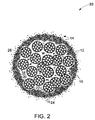
幾つかの実施形態では、シェルの三次微粒子はコア微粒子構造体の内部にも存在している。一実施形態では、三次微粒子及び三次細孔が1以上の一次微粒子を実質的に囲繞して、コア微粒子構造体の内部に小さいコアシェル構造体を形成している。粒子の表面積の約75%超が覆われた場合、微粒子は「実質的に囲繞」といわれる。幾つかの実施形態では、三次微粒子及び三次細孔は多くの一次微粒子を実質的に囲繞し得る。若干の他の実施形態では、三次微粒子及び三次細孔は実質的にすべての一次微粒子を実質的に囲繞している。本明細書で使用する「実質的にすべての微粒子」とは、微粒子の総数の約75%以上を意味する。かかるコアシェルセラミック微粒子の略図を図2に示す。 In some embodiments, the shell tertiary particulate is also present within the core particulate structure. In one embodiment, the tertiary fine particles and the tertiary pores substantially surround one or more primary fine particles to form a small core-shell structure inside the core fine particle structure. A microparticle is said to be “substantially surrounded” if more than about 75% of the surface area of the particle is covered. In some embodiments, the tertiary particulates and tertiary pores can substantially surround many primary particulates. In some other embodiments, the tertiary particulates and tertiary pores substantially surround substantially all of the primary particulates. As used herein, “substantially all microparticles” means about 75% or more of the total number of microparticles. A schematic diagram of such core-shell ceramic particulates is shown in FIG.
幾つかの実施形態では、三次微粒子は一次微粒子の内部に存在している。一実施形態では、三次微粒子及び三次細孔が1以上の二次微粒子を実質的に囲繞して、一次微粒子の内部にさらに小さいコアシェル構造体を形成し得る。幾つかの実施形態では、三次微粒子及び三次細孔は一部の二次微粒子を実質的に囲繞し得る。他の実施形態では、三次微粒子及び三次細孔は実質的にすべての二次微粒子を実質的に囲繞し得る。かかるコアシェルセラミック微粒子の略図を図2に示す。 In some embodiments, the tertiary particulate is present within the primary particulate. In one embodiment, the tertiary microparticles and secondary microparticles having one or more tertiary pores can be substantially surrounded to form a smaller core-shell structure within the primary microparticles. In some embodiments, the tertiary particulates and tertiary pores can substantially surround some of the secondary particulates. In other embodiments, the tertiary particulates and tertiary pores can substantially surround substantially all secondary particulates. A schematic diagram of such core-shell ceramic particulates is shown in FIG.
細孔サイズ及び細孔サイズ分布の正確な制御は、多孔質セラミック構造体の性能を画定するパラメーターの1つである。一次、二次及び三次細孔の細孔サイズは、セラミック構造体の最終用途に基づいて選択される。本発明の実施形態に係るコアシェルセラミック微粒子は、マクロスケール、メソスケール又はマイクロスケール上に多モードの多孔度をもった階層的多孔質構造を有している。微粒子全体に関する一次、二次及び三次細孔サイズは、メジアン一次、二次又は三次細孔サイズのような統計的尺度で特徴づけることができる。幾つかの実施形態では、一次、二次又は三次細孔の各々は多モード(例えば、二モード)の細孔構造を有し得るが、これは特定クラスの細孔が母集団に2以上の異なる細孔サイズを有することを意味する。かかる実施形態では、これらの細孔は階層的多孔質構造に関連していることもあれば、関連していないこともある。 Accurate control of pore size and pore size distribution is one of the parameters that define the performance of porous ceramic structures. The pore size of the primary, secondary and tertiary pores is selected based on the end use of the ceramic structure. The core-shell ceramic fine particles according to the embodiment of the present invention have a hierarchical porous structure having multimodal porosity on a macroscale, mesoscale, or microscale. Primary, secondary and tertiary pore sizes for the entire microparticle can be characterized by statistical measures such as median primary, secondary or tertiary pore size. In some embodiments, each of the primary, secondary or tertiary pores can have a multimodal (eg, bimodal) pore structure, which means that a particular class of pores has two or more in the population It means having different pore sizes. In such embodiments, these pores may or may not be associated with a hierarchical porous structure.
一般に、メジアン一次細孔径はメジアン二次細孔径と異なり、メジアン二次細孔径はメジアン三次細孔径とは異なる。幾つかの実施形態では、メジアン一次細孔径は、複数の二次細孔のメジアン二次細孔径及び/又は複数の三次細孔のメジアン三次細孔径より大きい。一実施形態では、メジアン一次細孔径はメジアン二次細孔径より約2倍以上大きい。他の実施形態では、メジアン一次細孔径はメジアン二次細孔径より10倍以上大きい。幾つかの実施形態では、メジアン一次細孔径はメジアン二次細孔径より大きいが、メジアン三次細孔径より小さい。一実施形態では、メジアン一次細孔径はメジアン二次細孔径より2倍以上大きく、メジアン三次細孔径はメジアン二次細孔径より2倍以上大きい。一実施形態では、メジアン一次細孔径はメジアン二次細孔径より2倍以上大きく、メジアン三次細孔径はメジアン二次細孔径より10倍以上大きい。しかし、幾つかの実施形態では、メジアン一次細孔径はメジアン二次細孔径より大きく、メジアン二次細孔径はメジアン三次細孔径より大きい。微粒子の正確な多孔度及び細孔径は、以下の実施形態でさらに詳しく記載されるように、特定の用途のために要求される多孔質構造に依存する。 In general, the median primary pore size is different from the median secondary pore size, and the median secondary pore size is different from the median tertiary pore size. In some embodiments, the median primary pore size is greater than the median secondary pore size of the plurality of secondary pores and / or the median tertiary pore size of the plurality of tertiary pores. In one embodiment, the median primary pore size is about 2 times greater than the median secondary pore size. In other embodiments, the median primary pore size is at least 10 times greater than the median secondary pore size. In some embodiments, the median primary pore size is larger than the median secondary pore size but smaller than the median tertiary pore size. In one embodiment, the median primary pore size is at least twice as large as the median secondary pore size, and the median tertiary pore size is at least twice as large as the median secondary pore size. In one embodiment, the median primary pore size is at least twice as large as the median secondary pore size, and the median tertiary pore size is at least 10 times greater than the median secondary pore size. However, in some embodiments, the median primary pore size is greater than the median secondary pore size, and the median secondary pore size is greater than the median tertiary pore size. The exact porosity and pore size of the microparticles will depend on the required porous structure for the particular application, as described in more detail in the following embodiments.
幾つかの実施形態では、複数の一次、二次及び三次細孔は有利には開放多孔質構造を有するが、これは大部分の細孔が表面に開いていることを意味する。開放細孔は多孔質構造内の出入り可能な細孔部分を表すが、これはこれらの細孔及び通路が互いに連結又は結合されて材料全体を通じて液体又は気体を移動させるための完全な流路を生じることを意味する。しかし、複数の細孔の小部分は閉鎖多孔質構造を有していてもよい。多モードの多孔度を有する開放状態の明確に画成された階層的多孔質構造は、活性表面積及び検体の拡散を増加させて多孔質構造体の性能を向上させる。 In some embodiments, the plurality of primary, secondary and tertiary pores advantageously have an open porous structure, meaning that most of the pores are open to the surface. Open pores represent the portion of the pores that can enter and exit within a porous structure, which is a complete flow path through which the pores and passages are connected or coupled together to move liquids or gases through the material. It means to occur. However, a small portion of the plurality of pores may have a closed porous structure. An open, well-defined hierarchical porous structure with multimodal porosity increases the active surface area and analyte diffusion to improve the performance of the porous structure.
コア微粒子構造体を構成する一次微粒子及び二次微粒子のサイズ、充填密度及びくびれは、コア微粒子構造体の細孔サイズ及び多孔度を決定する。三次微粒子がコア中に存在する実施形態では、これらはコア構造体の多孔度を画定するのに寄与する。同様に、シェル構造を構成する三次微粒子のサイズ、充填密度及びくびれは、シェルの細孔サイズ及び多孔度を決定する。一実施形態では、一次微粒子は約100nm〜約1ミクロンの範囲内のメジアン粒径を有する。別の実施形態では、一次微粒子は約300〜約700nmの範囲内のメジアン粒径を有する。一実施形態では、二次微粒子は約2〜約50nmの範囲内のメジアン粒径を有する。別の実施形態では、二次微粒子は約5〜約30nmの範囲内のメジアン粒径を有する。一実施形態では、三次微粒子は約5〜約300nmの範囲内のメジアン粒径を有する。別の実施形態では、三次微粒子は約10〜約100nmの範囲内のメジアン粒径を有する。複数の微粒子の各々は実質的に球状の形状を有していてもよい。別法として、小板、繊維、棒、楕円体などのような他の形態も可能である。 The size, packing density, and constriction of the primary fine particles and the secondary fine particles constituting the core fine particle structure determine the pore size and the porosity of the core fine particle structure. In embodiments where tertiary particulates are present in the core, they contribute to defining the porosity of the core structure. Similarly, the size, packing density, and constriction of the tertiary fine particles constituting the shell structure determine the pore size and porosity of the shell. In one embodiment, the primary microparticles have a median particle size in the range of about 100 nm to about 1 micron. In another embodiment, the primary microparticles have a median particle size in the range of about 300 to about 700 nm. In one embodiment, the secondary particulate has a median particle size in the range of about 2 to about 50 nm. In another embodiment, the secondary particulate has a median particle size in the range of about 5 to about 30 nm. In one embodiment, the tertiary particulate has a median particle size in the range of about 5 to about 300 nm. In another embodiment, the tertiary particulate has a median particle size in the range of about 10 to about 100 nm. Each of the plurality of fine particles may have a substantially spherical shape. Alternatively, other forms such as platelets, fibers, rods, ellipsoids, etc. are possible.
幾つかの実施形態では、コア微粒子構造体は約20〜約70%の範囲内の多孔度を有している。他の実施形態では、コア微粒子構造体は約30〜約50%の範囲内の多孔度を有している。幾つかの実施形態では、シェルは約20〜約70%の範囲内の多孔度を有している。他の実施形態では、シェルは約30〜約50%の範囲内の多孔度を有している。構造体の実際の多孔度は、最終用途の要求条件(例えば、所要の流量及び表面積)を満たすように最適化される。多孔度構造体の構造的健全性を保持しながら達成可能な多孔度は、構成材料及びコアシェル微粒子を製造するために選択される方法に依存する。 In some embodiments, the core particulate structure has a porosity in the range of about 20 to about 70%. In other embodiments, the core particulate structure has a porosity in the range of about 30 to about 50%. In some embodiments, the shell has a porosity in the range of about 20 to about 70%. In other embodiments, the shell has a porosity in the range of about 30 to about 50%. The actual porosity of the structure is optimized to meet end use requirements (eg, required flow rate and surface area). The porosity that can be achieved while maintaining the structural integrity of the porous structure depends on the material selected and the method selected to produce the core-shell particulate.
幾つかの実施形態では、コア微粒子構造体は約1〜約150μmの範囲内の最大寸法を有している。他の実施形態では、コア微粒子構造体は約5〜約50μmの範囲内の寸法を有している。シェルは約5nm以上の厚さを有している。幾つかの実施形態では、シェルは約5〜約500nmの厚さを有している。シェルは単一の層を有していてもよいし、同一又は異種の材料からなる複数の層を有していてもよい。 In some embodiments, the core particulate structure has a maximum dimension in the range of about 1 to about 150 μm. In other embodiments, the core particulate structure has a dimension in the range of about 5 to about 50 μm. The shell has a thickness of about 5 nm or more. In some embodiments, the shell has a thickness of about 5 to about 500 nm. The shell may have a single layer or a plurality of layers made of the same or different materials.
コアの材料(以下、コア材料という)及びシェルの材料(以下、シェル材料という)は、最終用途に基づいて選択される。シェル及びコアの材料は、これらが装置の動作温度で機械的及び構造的に安定であると共に、必要な構造的健全性を与えるように選択される。コアは、酸化物、窒化物、炭化物、ホウ化物又はカルコゲン化物を始めとするセラミック材料からなる。幾つかの実施形態では、コア微粒子構造体は2種以上のセラミックからなる。幾つかの実施形態では、コア微粒子構造体はセラミック複合材からなる。好適なセラミックの例には、特に限定されないが、ジルコニア、安定化ジルコニア、イットリア安定化ジルコニア、アルミナ、チタニア、セリア、ドープトセリア、サマリアドープトセリア、ガドリニアドープトセリア、シリカ、イットリア、酸化亜鉛、酸化スズ及び酸化マグネシウムがある。幾つかの実施形態では、コアは酸化鉄含有微粒子、光磁気材料又は強誘電性材料のような磁性材料からなる。例示的な実施形態では、酸化物はイットリア安定化ジルコニアからなる。構造材料としては、イットリア安定化ジルコニアは室温から約2500℃まで相変化を示さず、高温動作のために魅力的である。安定化ジルコニア及びチタニアは水溶液中で安定であり、そのために液体分離用の好適な材料である。ジルコニア及びドープトセリアは高温で高いイオン伝導率を有しており、そのためにセンサー及び燃料電池用のイオン伝導性電極に適したコア材料である。 The core material (hereinafter referred to as the core material) and the shell material (hereinafter referred to as the shell material) are selected based on the end use. The shell and core materials are selected so that they are mechanically and structurally stable at the operating temperature of the device and provide the necessary structural integrity. The core is made of a ceramic material including oxide, nitride, carbide, boride or chalcogenide. In some embodiments, the core particulate structure consists of two or more ceramics. In some embodiments, the core particulate structure comprises a ceramic composite. Examples of suitable ceramics include, but are not limited to, zirconia, stabilized zirconia, yttria stabilized zirconia, alumina, titania, ceria, doped ceria, samaria doped ceria, gadolinia doped ceria, silica, yttria, zinc oxide, oxidation There are tin and magnesium oxide. In some embodiments, the core is made of a magnetic material such as iron oxide-containing particulates, a magneto-optical material or a ferroelectric material. In an exemplary embodiment, the oxide comprises yttria stabilized zirconia. As a structural material, yttria stabilized zirconia exhibits no phase change from room temperature to about 2500 ° C. and is attractive for high temperature operation. Stabilized zirconia and titania are stable in aqueous solutions and are therefore suitable materials for liquid separation. Zirconia and doped ceria have high ionic conductivity at high temperatures and are therefore suitable core materials for sensors and ion conductive electrodes for fuel cells.
同様に、シェルは任意のセラミック材料(例えば、酸化物、窒化物、炭化物、ホウ化物又はカルコゲン化物)からなるものでもよい。通例、シェル材料はある種の環境条件に対して敏感な1以上の物理的性質(例えば、導電率、イオン伝導率、熱膨張など)を有しており、したがってコアシェル微粒子はセンサー材料として使用できる。例えば、フェライトは酸素分圧に対して敏感な導電率を有しており、酸素センサー材料として使用できる。好適なシェル材料の例には、特に限定されないが、フェライト、銅酸塩(cuprates)、ルテニウム酸塩(ruthenates)、クロム酸塩(chromates)、コバルト酸塩(cobaltates)、ニッケル酸塩(nickelates)、リン酸塩、チタン酸塩(titanates)、マンガン酸塩(manganates)及びケイ酸塩がある。例示的な実施形態では、シェルはランタンフェライトからなる。これらのシェル材料は、その感知特性を最適化するために導入されたある種のドーパントを含んでいてもよい。かかるドーパントの例には、特に限定されないが、アルカリ金属元素、アルカリ土類金属元素、希土類元素、遷移金属元素又はこれらの組合せがある。半導体酸化物ガスセンサーの場合、例示的なシェル材料には、二酸化スズ、チタニア、チタン酸バリウム、酸化タングステン又はスズ酸バリウムがある。電気化学的ガスセンサーの場合、例示的なシェル材料には、ペロブスカイト型酸化物(例えば、フェライト、コバルト酸塩、マンガン酸塩、ルテニウム酸塩、クロム酸塩及びニッケル酸塩)がある。 Similarly, the shell may be composed of any ceramic material (eg, oxide, nitride, carbide, boride or chalcogenide). Typically, the shell material has one or more physical properties (eg, conductivity, ionic conductivity, thermal expansion, etc.) that are sensitive to certain environmental conditions, and thus the core shell particulate can be used as a sensor material. . For example, ferrite has a conductivity sensitive to oxygen partial pressure, and can be used as an oxygen sensor material. Examples of suitable shell materials include, but are not limited to, ferrites, cuprates, ruthenates, chromates, cobaltates, nickelates. , Phosphates, titanates, manganates and silicates. In an exemplary embodiment, the shell is made of lanthanum ferrite. These shell materials may contain certain dopants introduced to optimize their sensing properties. Examples of such dopants include, but are not limited to, alkali metal elements, alkaline earth metal elements, rare earth elements, transition metal elements, or combinations thereof. For semiconductor oxide gas sensors, exemplary shell materials include tin dioxide, titania, barium titanate, tungsten oxide, or barium stannate. For electrochemical gas sensors, exemplary shell materials include perovskite oxides (eg, ferrites, cobaltates, manganates, ruthenates, chromates and nickelates).
幾つかの実施形態では、シェル材料は触媒材料からなる。例えば、触媒材料を使用することで、流体分離と触媒反応とを組み合わせて効率の高い流体混合物分離を達成することが可能である。触媒反応は、1種以上の反応生成物の濃度を低下させ、したがって転化効率を高めるために使用できる。触媒材料はまた、マイクロリアクター、ゲッター、電極又はセンサー用途のために含めることもできる。好適な触媒材料の若干の例には、特に限定されないが、遷移金属及びその酸化物、酸化銅、セリア、チタニア、ペロブスカイト、酸化亜鉛、酸化マンガン、酸化タングステン、酸化スズ、アルミナ又はこれらの組合せがある。当業者であれば、所望の反応及び所定の作業環境に基づいて触媒材料を選択する方法には精通しているであろう。特異な感知特性を達成するため、シェルは同一又は異種の材料を含む複数の層からなるものでもよい。 In some embodiments, the shell material comprises a catalyst material. For example, by using a catalytic material, it is possible to achieve fluid mixture separation with high efficiency by combining fluid separation and catalytic reaction. Catalytic reactions can be used to reduce the concentration of one or more reaction products and thus increase conversion efficiency. Catalytic materials can also be included for microreactor, getter, electrode or sensor applications. Some examples of suitable catalyst materials include, but are not limited to, transition metals and oxides thereof, copper oxide, ceria, titania, perovskite, zinc oxide, manganese oxide, tungsten oxide, tin oxide, alumina, or combinations thereof. is there. Those skilled in the art will be familiar with methods for selecting catalyst materials based on the desired reaction and the desired working environment. In order to achieve unique sensing properties, the shell may consist of multiple layers comprising the same or different materials.
一実施形態では、コアシェルセラミック微粒子は熱的に安定である。即ち、約1000℃まで分解又は融解を受けない。セラミック複合材はまた、約1000℃まで構造的にも安定である。即ち、セラミックコアもセラミックシェルも、この温度以下では結晶構造又は結晶形態の実質的な変化を受けない。 In one embodiment, the core shell ceramic particulate is thermally stable. That is, it does not undergo decomposition or melting up to about 1000 ° C. Ceramic composites are also structurally stable up to about 1000 ° C. That is, neither the ceramic core nor the ceramic shell undergoes a substantial change in crystal structure or crystal form below this temperature.
一実施形態では、本発明の実施形態に係る複数のコアシェルセラミック微粒子を含んでなる物品が提供される。微粒子の候補材料及び固有サイズは前記に説明した。本発明のコアシェルセラミック微粒子は、特に限定されないが、フラット、半球、ドーム、コーン及び他の複雑な形状のような近似ネット造形品に形成できる。かかるコンパクト構造体は多孔質セラミック膜として使用できる。近似ネット造形品を得るためには、圧縮成形及び焼結、粒子の官能化を伴うか又は伴わない自己集合、或いはスリップキャスティング、ゲルキャスティング又は他の近似ネット造形品形成技術を始めとする公知技術のいずかを使用できる。別法として、コアシェルセラミック微粒子は基体の表面上に設けられたコーティングの形態を有していてもよい。コーティングを得るためには、プラズマ溶射、浸し塗り、電気泳動塗装などを始めとする当技術分野で公知の任意の被覆技術を使用できる。本発明の実施形態に係るコアシェルセラミック微粒子は構造的健全性を保持しており、加工のために必要となることがある高温に暴露された場合に焼結粒子によく見られる結晶粒成長現象を受けにくい。理論によって制約されることは望まないが、コア微粒子を囲繞するシェル材料は高温プロセスに暴露された場合にコア及びシェル構造体の両方の望ましくない結晶粒成長を防止すると考えられる。 In one embodiment, an article comprising a plurality of core-shell ceramic particulates according to embodiments of the present invention is provided. The candidate material and specific size of the fine particles are described above. The core-shell ceramic particles of the present invention are not particularly limited, but can be formed into approximate net shaped articles such as flats, hemispheres, domes, cones and other complex shapes. Such a compact structure can be used as a porous ceramic membrane. To obtain an approximate net shape product, known techniques such as compression molding and sintering, self-assembly with or without particle functionalization, or slip casting, gel casting or other approximate net shape forming technology You can use any of them. Alternatively, the core shell ceramic particulates may have the form of a coating provided on the surface of the substrate. Any coating technique known in the art can be used to obtain the coating, including plasma spraying, dipping, electrophoretic coating, and the like. Core-shell ceramic particulates according to embodiments of the present invention retain structural integrity and exhibit a grain growth phenomenon commonly seen in sintered particles when exposed to high temperatures that may be required for processing. It is hard to receive. While not wishing to be bound by theory, it is believed that the shell material surrounding the core particulates prevents unwanted grain growth of both the core and shell structures when exposed to high temperature processes.
本発明の実施形態に係るコアシェルセラミック微粒子は、膜構造体を製造するために使用できる。セラミック膜構造体の多くは、特定の用途のために必要な所望の機能性を達成するため、異なる多孔度、細孔構造及び機能性を有する複数のセラミック層を含む。例えば、非対称膜は細孔サイズ及び多孔度の異なる複数の層を有している。成層構造体中に触媒層を挿入することができ、及び/又は一部の層を触媒材料で被覆することができる。コアシェル微粒子の製造は、適切なコア及びシェル構造の組合せを選択することで、単一の微粒子中で様々な機能性を達成することを容易にする。かかる実施形態では、シェル材料は触媒からなり得る。多層シェル構造を有するコアシェル粒子は、複数の機能性を可能にする。例えば、シェルは、一酸化炭素、炭化水素、アンモニア、硫化水素及び二酸化硫黄のような還元ガスを検出できるセンサー材料である酸化クロムチタンの層と、オゾン、二酸化窒素及び塩素のような酸化ガスを検出できる酸化タングステンの層とを含むことで、二重センサーを得ることができる。 The core-shell ceramic fine particles according to the embodiment of the present invention can be used for producing a membrane structure. Many of the ceramic membrane structures include multiple ceramic layers with different porosity, pore structure and functionality to achieve the desired functionality required for a particular application. For example, the asymmetric membrane has a plurality of layers having different pore sizes and porosity. A catalyst layer can be inserted into the stratified structure and / or some layers can be coated with the catalyst material. The manufacture of core-shell microparticles facilitates achieving various functionalities in a single microparticle by selecting the appropriate core and shell structure combination. In such embodiments, the shell material can comprise a catalyst. Core shell particles having a multi-layer shell structure allow for multiple functionalities. For example, the shell contains a layer of chromium titanium oxide, a sensor material that can detect reducing gases such as carbon monoxide, hydrocarbons, ammonia, hydrogen sulfide and sulfur dioxide, and oxidizing gases such as ozone, nitrogen dioxide and chlorine. By including a layer of tungsten oxide that can be detected, a dual sensor can be obtained.
本発明のコアシェルセラミック微粒子は、多数の用途で有用であり得る。幾つかの実施形態では、コアシェルセラミック微粒子は分離アセンブリの一部である。コアシェルセラミック微粒子は上述のような多孔質セラミック膜構造体の形態に製造でき、かかる膜を空気分離アセンブリに使用できる。本発明の幾つかの実施形態におけるセラミック膜は、低品質天然ガスの精製、空気分離、NOx分離、酸素分離、或いはプロセスガス又は供給原料からの水素回収のために適した分子ふるい分けを行うことができる。一実施形態では、本発明のセラミック膜構造体は、窒素、アルゴン、二酸化炭素又はメタンからの水素分離のために使用できる。別の実施形態では、本発明のセラミック膜構造体は空気流から揮発性有機成分を分離するために使用できる。幾つかの実施形態では、セラミック構造体は高温ガス分離ユニットの一部である。かかる用途のためには、セラミック構造体の1以上の層上に適当な金属被膜又は複合材被膜が適用できる。別法として、セラミック構造体と共に金属層又は複合材層を使用することもできる。 The core shell ceramic particulates of the present invention may be useful in a number of applications. In some embodiments, the core shell ceramic particulate is part of a separation assembly. Core shell ceramic particulates can be manufactured in the form of a porous ceramic membrane structure as described above, and such membranes can be used in air separation assemblies. Ceramic membranes of some embodiments of the present invention, purification of low quality natural gas, air separation, NO x separation, oxygen separation, or by performing a sieving molecules suitable for hydrogen recovery from process gas or feed Can do. In one embodiment, the ceramic membrane structure of the present invention can be used for hydrogen separation from nitrogen, argon, carbon dioxide or methane. In another embodiment, the ceramic membrane structure of the present invention can be used to separate volatile organic components from an air stream. In some embodiments, the ceramic structure is part of a hot gas separation unit. For such applications, a suitable metal coating or composite coating can be applied on one or more layers of the ceramic structure. Alternatively, a metal layer or composite layer can be used with the ceramic structure.
図3は、本発明の一実施形態に係る簡単なガス分離ユニット40の略図を示している。ユニット40は、膜分離ユニット46に連結された圧縮機42、凝集フィルター43及び予熱器ユニット44を備える。加圧下の空気はまず凝集フィルター43を通過し、次いで予熱器ユニット44を通過してから、膜分離ユニット46に到達する。凝集フィルターは、供給物から油滴、水滴又は個体微粒子を除去するために使用できる。膜分離ユニットは、空気混合物から所望成分を除去するように構成された本発明の膜構造体の1以上を備える。所望成分は出口47を通過し、残った廃浸透ガスは出口48から出る。膜分離ユニットは、追加のヒーター又は追加のフィルターを備えていてもよい。
FIG. 3 shows a schematic diagram of a simple
膜構造体は、例えば、有機成分を含む流体から水を分離するための液−液分離アセンブリとして使用できる。かかる用途のためには、膜構造体は必要ならば他の多孔質又は非孔質分離層と併用できる。一実施形態では、適当な厚さの非孔質架橋ポリビニルアルコール層からなる分離層が膜構造体と共に使用される。各層の細孔構造及び厚さは、要求条件に応じて調整できる。幾つかの実施形態では、膜構造体は、汚れを防止するため細孔内壁上に塗布された反応体成分を含む、分離アセンブリの膜構造体であり得る。 The membrane structure can be used, for example, as a liquid-liquid separation assembly for separating water from a fluid containing organic components. For such applications, the membrane structure can be used in combination with other porous or nonporous separation layers if desired. In one embodiment, a separation layer comprising a non-porous crosslinked polyvinyl alcohol layer of appropriate thickness is used with the membrane structure. The pore structure and thickness of each layer can be adjusted according to requirements. In some embodiments, the membrane structure can be a membrane structure of a separation assembly that includes reactant components applied on the pore inner walls to prevent fouling.
一実施形態では、コアシェルセラミック微粒子からなる膜構造体は濾過アセンブリの一部である。層の細孔寸法を調節することで、本発明の膜構造体は、約10μm未満の寸法をもった固体粒子を濾別するためのマイクロ濾過、又は最小約50nmまでの寸法をもった粒子(例えば、巨大分子及び細菌)を濾別するための限外濾過用として使用できる。層の細孔寸法を非常に小さいサイズに選択することで、これらの膜構造体を、さらに小さい単位(例えば、糖、モノマー、アモノ酸又は溶存イオン)を逆浸透で濾別するための超濾過用として使用することも可能である。一実施形態では、膜構造体は生体分離又は反応アセンブリの一部である。膜層の細孔サイズ及び厚さは、分離すべき種のサイズに応じて選択される。したがって、一実施形態では、膜構造体は食品用途、医薬品用途及び工業的用途で使用可能なフィルターである。別の実施形態では、膜構造体はタンパク質精製ユニットの一部である。 In one embodiment, the membrane structure composed of core-shell ceramic particulates is part of a filtration assembly. By adjusting the pore size of the layer, the membrane structure of the present invention can be microfiltered to filter out solid particles having a size of less than about 10 μm, or particles having a size of up to about 50 nm ( For example, it can be used for ultrafiltration for separating macromolecules and bacteria). By selecting the pore size of the layer to a very small size, these membrane structures can be ultrafiltered to filter out smaller units (eg sugars, monomers, ammono acids or dissolved ions) by reverse osmosis. It can also be used as an application. In one embodiment, the membrane structure is part of a bioseparation or reaction assembly. The pore size and thickness of the membrane layer is selected depending on the size of the species to be separated. Thus, in one embodiment, the membrane structure is a filter that can be used in food applications, pharmaceutical applications, and industrial applications. In another embodiment, the membrane structure is part of a protein purification unit.
図4は、本発明の一実施形態に係る簡単なフィルターユニット50の略図である。ユニット50は、分離すべき物質を含む液体媒質を貯蔵するために使用する供給材料タンク52を備える。供給材料53の循環は、ライン56及び58を通して供給材料53を膜フィルターアセンブリ60に輸送するポンプ54で制御される。膜フィルターアセンブリ60は、供給材料から特定成分を濾別するように構成された本発明の膜構造体の1以上を備える。所望成分の「濾液」57は出口59を通過し、保持液(リテンテート)62は除去するか又は供給材料タンク52に戻すことができる。
FIG. 4 is a schematic diagram of a
多孔質膜構造体を含む多くの用途(例えば、濾過又は分離用途)での一般的な問題は、流量(「パーミアンス」という)が膜構造体の細孔サイズに強く依存することである。迅速な物質移動は、細孔サイズを増大させることで達成される。しかし、細孔サイズを増大させると、膜の選択性又は反応性が低下する。したがって、一般には、物質移動と選択性との間でトレードオフを行わなければならない。物質移動を増加させる方法の1つは、本発明の実施形態に係る階層的多孔質構造を利用することである。かかる構造では、粒子表面からの大きいフィーダー細孔が、吸着に利用できる大きい表面積をもつ小さな細孔径のネットワークに開いているか、或いはその逆になっている。 A common problem in many applications involving porous membrane structures (eg, filtration or separation applications) is that the flow rate (referred to as “permeance”) is strongly dependent on the pore size of the membrane structure. Rapid mass transfer is achieved by increasing the pore size. However, increasing pore size decreases membrane selectivity or reactivity. Therefore, in general, a trade-off must be made between mass transfer and selectivity. One way to increase mass transfer is to utilize a hierarchical porous structure according to embodiments of the present invention. In such a structure, large feeder pores from the particle surface are open to a small pore size network with a large surface area available for adsorption, or vice versa.
一実施形態では、コアシェルセラミック微粒子はセンサーアセンブリの一部である。かかる実施形態では、可逆的変化を行い得る材料でコア及び/又はシェル層を構成するか、或いは上述のような官能基をセラミック構造体に導入することでコア及び/又はシェル層を官能化すればよい。可逆的変化の例には、特に限定されないが、イオン化、酸化、還元、水素結合、金属錯体化、異性化及び共有結合のような化学反応がある。これらの変化は、化学種又は生物種を検出するため、或いは温度、pH、イオン強度、電位、光の強さ、又は光の波長の変化を検出するために利用できる。センサー用途のためにセラミック構造体を使用することは、それの表面/体積比が大きいので検出性能を高めると予想される。 In one embodiment, the core shell ceramic particulate is part of a sensor assembly. In such an embodiment, the core and / or shell layer may be composed of a material capable of undergoing reversible changes, or the core and / or shell layer may be functionalized by introducing functional groups as described above into the ceramic structure. That's fine. Examples of reversible changes include, but are not limited to, chemical reactions such as ionization, oxidation, reduction, hydrogen bonding, metal complexation, isomerization, and covalent bonding. These changes can be used to detect chemical or biological species or to detect changes in temperature, pH, ionic strength, potential, light intensity, or light wavelength. The use of a ceramic structure for sensor applications is expected to enhance detection performance because of its large surface / volume ratio.
例示的な実施形態では、コアシェルセラミック微粒子は高温ガスセンサーを製造するために使用される。かかる実施形態では、シェル/コア構造体は、ガス状の化合物又は化合物混合物に暴露されるとその物理的性質の1以上(例えば、質量、導電率又はキャパシタンス)を変化させると共に、その変化を直接又は間接に測定及び定量できる材料を含んでいてもよい。ガス感知材料のホストは当技術分野で公知であり、要求情報及び作業環境に応じて任意適宜の材料を選択できる。材料を選択する際に基準として使用する公知パラメーターには、とりわけ、短い応答時間、良好な応答信号、容易な製造可能性、安い価格、高い選択性及び長期安定性がある。例えば、酸化亜鉛、酸化スズ、二酸化タングステン、酸化マンガン及び他の遷移金属酸化物のような半導体酸化物は、高温ガス感知用途のために適している。ガス感知機構は、これらの酸化物の表面上への酸素の化学吸着、次いで酸素と標的ガス分子との反応中における電荷移動を含んでいて、これがセンサーの表面上の抵抗を変化させる。本発明の実施形態に係るコアシェル構造体の大きい表面積は、ガス感知用途に対して明確な利点を与える。コア及びシェル構造体の構造的及び機械的安定性は、追加の利益をもたらす。 In an exemplary embodiment, the core shell ceramic particulate is used to manufacture a hot gas sensor. In such embodiments, the shell / core structure changes one or more of its physical properties (eg, mass, conductivity, or capacitance) when exposed to a gaseous compound or mixture of compounds and directly changes the change. Alternatively, a material that can be indirectly measured and quantified may be included. Hosts for gas sensing materials are known in the art, and any suitable material can be selected according to required information and work environment. Known parameters used as criteria in selecting materials include short response time, good response signal, easy manufacturability, low cost, high selectivity and long-term stability. For example, semiconductor oxides such as zinc oxide, tin oxide, tungsten dioxide, manganese oxide and other transition metal oxides are suitable for high temperature gas sensing applications. The gas sensing mechanism involves the chemisorption of oxygen on the surface of these oxides, followed by charge transfer during the reaction of oxygen with target gas molecules, which changes the resistance on the surface of the sensor. The large surface area of the core-shell structure according to embodiments of the present invention provides a distinct advantage for gas sensing applications. The structural and mechanical stability of the core and shell structure provides additional benefits.
一実施形態では、物品はゲッターアセンブリの一部である。ゲッターは、半導体加工での空気浄化、真空システム、光学用途及び宇宙用途で広く使用されている。物理ゲッターは、混合物から水蒸気、微粒子又は夾雑物を物理的に吸収して保持する。他方、化学ゲッターは化学反応を介して混合物から特定の化合物を除去する。各種のセラミック材料が特定のガス分子に対して親和性を有することが知られており、したがって特定のガス分子のゲッターとして使用できる。例えば、H2Sに対して有効な吸着剤には、特に限定されないが、酸化亜鉛、酸化鉄、亜鉄酸亜鉛、ランタンフェライト及び銅酸ランタンがある。CO2に対して有効な吸着剤には、特に限定されないが、炭酸カルシウム、ケイ酸リチウム及びジルコン酸リチウムがある。 In one embodiment, the article is part of a getter assembly. Getters are widely used in air purification, vacuum systems, optical applications and space applications in semiconductor processing. The physical getter physically absorbs and holds water vapor, fine particles, or impurities from the mixture. On the other hand, chemical getters remove specific compounds from the mixture through chemical reactions. Various ceramic materials are known to have affinity for specific gas molecules and can therefore be used as getters for specific gas molecules. For example, effective adsorbents for H 2 S include, but are not limited to, zinc oxide, iron oxide, zinc ferrite, lanthanum ferrite, and lanthanum cuprate. Adsorbents effective for CO 2 include, but are not limited to, calcium carbonate, lithium silicate and lithium zirconate.
本発明の実施形態に係るコアシェルセラミック微粒子は、固体燃料電池のカソード又はアノードを作製するために使用できる。燃料電池(例えば、固体酸化物燃料電池(SOFC))は、イオン伝導層を介して燃料と酸化体とを電気化学的に化合させることで電気を発生するエネルギー変換装置である。例示的なプレーナー型燃料電池70は、図5に示すように、インターコネクト部分72と、電解質78で隔てられた1対の電極(カソード74及びアノード76)とを備える。
The core-shell ceramic particulates according to embodiments of the present invention can be used to make a solid fuel cell cathode or anode. A fuel cell (for example, a solid oxide fuel cell (SOFC)) is an energy conversion device that generates electricity by electrochemically combining a fuel and an oxidant via an ion conductive layer. An exemplary
インターコネクト部分72は、隣接した電池繰返し単位80のカソード74に緊密に接触した複数の空気流路84及びアノード76に緊密に接触した複数の燃料流路86を画成し、或いはその逆の構成も可能である。動作に際しては、燃料の流れ88が燃料流路86に供給され、空気(通例は加熱空気)の流れ90が空気流路84に供給される。
The
図6は燃料電池の一部を示す図であって、燃料電池の動作を図解している。図6に示すように、燃料の流れ88(例えば、天然ガス)はアノード76に供給されて酸化反応を受ける。燃料はアノードで、電解質を横切ってアノードに輸送される酸素イオン(O2−)と反応する。酸素イオン(O2−)は脱イオンされて外部電気回路94に電子を放出する。空気の流れ90はカソード74に供給され、外部電気回路94から電子を受け取って還元反応を受ける。電解質78はアノード76とカソード78との間でイオンを伝導する。電子の流れは直流電気を発生し、このプロセスは若干の廃ガス及び熱を生じる。
FIG. 6 is a diagram showing a part of the fuel cell, illustrating the operation of the fuel cell. As shown in FIG. 6, a fuel stream 88 (eg, natural gas) is supplied to the
アノード層76の主目的は、燃料電池に導入される燃料の電気化学的酸化のための反応部位を提供することである。さらに、アノード材料は燃料還元環境中で安定であり、十分な電子伝導率、表面積、及び燃料電池動作条件下での燃料ガス反応に対する触媒活性を有し、反応部位へのガス輸送を可能にするのに十分な多孔度を有する必要がある。電解質層の主目的は、アノード層76とカソード層74との間でイオンを伝導することである。電解質は一方の電極で生じたイオンを他方の電極に運ぶことで、電子の流れに由来する電荷をバランスさせて燃料電池中の電気回路を完結させる。さらに、電解質は燃料電池中で燃料を酸化体から隔離する。したがって、電解質は還元環境及び酸化環境の両方で安定であり、反応ガスに対して不透過性を有し、かつ動作条件下で十分な伝導性を有していなければならない。通例、電解質78は実質的に電子絶縁性である。カソード層74は電解質78上に設けられる。カソード層74の主目的は、酸化体の電気化学的還元のための反応部位を提供することである。したがって、カソード層74は酸化環境で安定であると共に、十分な電子及びイオン伝導性、十分な表面積、燃料電池動作条件下で酸化体ガス反応に対する触媒活性、並びに反応部位へのガス輸送を可能にするのに十分な多孔度を有していなければならない。
The main purpose of the
上述の通り、固体燃料電池のカソード/アノード用材料を選択する際に一般に使用する基準は、触媒活性、イオン伝導率、熱膨張率、電子伝導率及び安定性である。単一の材料で上記性質のすべてを達成するのは困難である。したがって、コアシェルセラミック微粒子の合成は2種以上の材料を組み合わせることを容易にし、それによって上記基準の多くを満たす可能性がある。例えば、YSZコア及びシェルとしてランタンフェライトストロンチウムを含むコアシェルセラミック微粒子は魅力的な組合せである。コアシェル微粒子の大きい表面積及び高度に相互連結された三次元多孔性は、燃料電池の触媒活性を高める。かかる実施形態では、シェル材料は所望の反応に適した触媒であり得る。一次微粒子及び/又は二次微粒子を囲繞することを含め、多孔質コアシェル構造体の全体にわたる触媒シェル材料の均一な分散は、触媒活性を大幅に高める。かかる実施形態では、コア及びシェルは適当な多孔質構造体からなるものでよい。例えば、シェルは外面に開いたメソ多孔質構造体からなるものでもよく、コアはマクロ多孔質構造体からなるものでもよい。かくして、構造体に対して燃料及び生成物を容易に拡散させるための通行自由のネットワークが活性触媒の周囲に提供される。一実施形態では、燃料電池はメタノール燃料電池である。メタノール燃料電池は水素の製造に使用できる。 As noted above, the commonly used criteria in selecting a solid fuel cell cathode / anode material are catalyst activity, ionic conductivity, thermal expansion, electronic conductivity and stability. It is difficult to achieve all of the above properties with a single material. Thus, the synthesis of core-shell ceramic particulates facilitates the combination of two or more materials, thereby potentially meeting many of the above criteria. For example, a core-shell ceramic particulate comprising a YSZ core and lanthanum ferrite strontium as the shell is an attractive combination. The large surface area of the core-shell particulates and the highly interconnected three-dimensional porosity increase the catalytic activity of the fuel cell. In such embodiments, the shell material can be a suitable catalyst for the desired reaction. Uniform distribution of the catalyst shell material throughout the porous core-shell structure, including surrounding the primary and / or secondary particulates, greatly enhances the catalytic activity. In such an embodiment, the core and shell may comprise a suitable porous structure. For example, the shell may be composed of a mesoporous structure that is open on the outer surface, and the core may be composed of a macroporous structure. Thus, a free-to-go network is provided around the active catalyst for easy diffusion of fuel and products to the structure. In one embodiment, the fuel cell is a methanol fuel cell. Methanol fuel cells can be used for hydrogen production.
本発明の別の態様は、コアシェルセラミック微粒子の製造方法を提供することである。図7は、本発明の一実施形態に係るコアシェルセラミック微粒子の製造方法110のフローチャートを示している。かかる方法は、複数の一次微粒子及び複数の一次細孔を含むコアを用意する段階112と、コア上に複数の三次微粒子及び複数の三次細孔を含むシェルを設ける段階114とを含んでなる。
Another aspect of the present invention is to provide a method for producing core-shell ceramic particulates. FIG. 7 shows a flowchart of a
通例、制御された階層的多孔度を有する多孔質構造体の製造は、マイクロエマルジョン法又はゾルゲル合成法のような多くの複雑な化学的方法を必要とする。一方、本発明の実施形態に係る方法はコアシェル微粒子を製造するための非常に簡単で融通のきく方法を提供する。特定の多孔度及び細孔構造を得るためにある種の界面活性剤又はフラックスが使用できるが、その詳細は以下に記載する。細孔サイズ及び多孔度は、ナノサイズ微粒子の粒径、粒度分布及び焼結条件を調節することで調整できる。 Typically, the production of porous structures with controlled hierarchical porosity requires many complex chemical methods such as microemulsion methods or sol-gel synthesis methods. On the other hand, the method according to an embodiment of the present invention provides a very simple and versatile method for producing core-shell microparticles. Certain surfactants or fluxes can be used to obtain specific porosity and pore structure, details of which are described below. The pore size and porosity can be adjusted by adjusting the particle size, particle size distribution, and sintering conditions of the nano-sized fine particles.
幾つかの実施形態では、多孔質コア微粒子構造体を安定化するため、所定のフラックス物質中でコア微粒子を適宜加熱する。フラックス用として好適な物質には、特に限定されないが、フッ化物、ホウ化物、硝酸塩、塩化物、酸化物、ヨウ化物、アルカリ金属炭酸塩、アルカリ土類金属炭酸塩及びこれらの組合せがある。例示的な実施形態では、フラックスは四ホウ化リチウム及びフッ化リチウムからなる。別の例示的な実施形態では、フラックスは四ホウ化リチウム及び硝酸ナトリウムからなる。これらのフラックスは、その低い融点、したがって比較的低い温度でコア多孔質構造体を結合して捕捉する能力に基づいて検討される。この方法はさらに、フラックス中においてコア微粒子構造体を約600〜約1200℃の範囲内の温度で加熱することを含んでいてもよい。通例、フラックスがコア微粒子構造体を均一に被覆して構造体を安定化するまで、コア微粒子を約0.5〜約3時間加熱する。 In some embodiments, in order to stabilize the porous core particle structure, the core particles are appropriately heated in a predetermined flux material. Suitable materials for the flux include, but are not limited to, fluorides, borides, nitrates, chlorides, oxides, iodides, alkali metal carbonates, alkaline earth metal carbonates, and combinations thereof. In an exemplary embodiment, the flux consists of lithium tetraboride and lithium fluoride. In another exemplary embodiment, the flux consists of lithium tetraboride and sodium nitrate. These fluxes are considered based on their low melting point, and therefore their ability to bind and trap core porous structures at relatively low temperatures. The method may further include heating the core particulate structure in the flux at a temperature in the range of about 600 to about 1200 ° C. Typically, the core particulate is heated for about 0.5 to about 3 hours until the flux uniformly coats the core particulate structure and stabilizes the structure.
幾つかの実施形態では、コア微粒子及び界面活性剤を含む分散液が、化学的に安定な保護被膜を得るのに十分な温度で十分な時間にわたり加熱される。かかる保護被膜は、加工中に微粒子を反応媒質から保護し得る。多数の商業的に入手可能な界面活性剤のいずれもが、本発明の実施形態で使用するのに適している。界面活性剤は、カチオン界面活性剤、アニオン界面活性剤、非イオン界面活性剤及びこれらの組合せからなる群から選択される1種以上の界面活性剤からなる。この場合、非イオン界面活性剤は極性界面活性剤、無極性界面活性剤及びこれらの組合せからなる群から選択される。 In some embodiments, the dispersion comprising the core microparticles and the surfactant is heated at a temperature sufficient for a sufficient time to obtain a chemically stable protective coating. Such a protective coating can protect the microparticles from the reaction medium during processing. Any of a number of commercially available surfactants are suitable for use in embodiments of the present invention. The surfactant is composed of one or more surfactants selected from the group consisting of cationic surfactants, anionic surfactants, nonionic surfactants, and combinations thereof. In this case, the nonionic surfactant is selected from the group consisting of polar surfactants, nonpolar surfactants, and combinations thereof.
シェルは、インサイチュ又はエクスサイチュで用意し、コア微粒子構造体上/中に設けることができる。シェル材料が被覆プロセス中に生成される場合、このプロセスはインサイチュといわれる。インサイチュプロセス(方法120)を図解するフローチャートを図8に示す。シェル材料が独立のプロセスで生成され、次いで本発明の方法でコア微粒子構造体上に設ける場合、このプロセスはエクスサイチュといわれる。図9は微粒子組成物を製造するためのエクスサイチュプロセス(方法130)を示している。 The shell may be provided in situ or ex situ and provided on / in the core particulate structure. If the shell material is produced during the coating process, this process is said to be in situ. A flowchart illustrating the in situ process (method 120) is shown in FIG. If the shell material is produced in an independent process and then provided on the core particulate structure in the method of the present invention, this process is referred to as ex situ. FIG. 9 illustrates an ex-situ process (method 130) for producing a particulate composition.
微粒子のサイズ及び形状は、組成物の実施形態に明記した粒径範囲及び形態を含めて様々に変化し得る。使用する微粒子は、当技術分野で公知の任意の合成方法で製造できる。一般に、微粒子は液体媒質中に分散した状態で用意される。任意適宜の液体媒質が使用できる。幾つかの実施形態では、液体媒質は水からなる。若干の他の実施形態では、液体媒質は有機溶媒である。幾つかの実施形態では、シェル材料の量は約2〜約30重量%の範囲内にあり、特定の実施形態では、この量は約2〜約25重量%の範囲内にある。 The size and shape of the microparticles can vary widely, including the particle size range and morphology specified in the composition embodiments. The fine particles used can be produced by any synthesis method known in the art. In general, fine particles are prepared in a dispersed state in a liquid medium. Any suitable liquid medium can be used. In some embodiments, the liquid medium consists of water. In some other embodiments, the liquid medium is an organic solvent. In some embodiments, the amount of shell material is in the range of about 2 to about 30% by weight, and in certain embodiments, this amount is in the range of about 2 to about 25% by weight.
シェル材料がインサイチュで(一般に段階122で)用意される場合、シェル構造を得るために必要な反応体が供給される。一般に、シェル材料の成分の前駆体を媒質中に仕込むことで溶液、ゲル、懸濁液、コロイド又は分散液が形成される。前駆体の非限定的な例には、硝酸塩、塩化物、アルコキシド、酢酸塩及び酸化物がある。媒質は、流動及び十分な混合を容易にするため、低い粘度を有するのが好ましい。段階124では、適当な媒質中でコア微粒子構造体の分散液が用意される。段階126では、コア微粒子構造体の分散液及びシェル材料前駆体を含む溶液を混合することで、ヒア上にシェル微粒子が配置される。プロセスがインサイチュである場合、簡単な熱処理を施すか、塩基性成分を添加して上記混合物のpHを高めるか、或いは混合物に燃料を添加することにより、段階128でシェル材料の中間組成物が沈殿する。任意適宜の塩基が使用できる。好適な塩基性成分の非限定的な例には、水酸化ナトリウム、水酸化テトラメチルアンモニウム、炭酸アンモニウム及び水酸化アンモニウムがある。燃料を使用する実施形態では、燃焼合成で使用される任意の燃料(例えば、グリシン)が使用できる。シェル材料の中間組成物は、段階129で反応温度に加熱することによって所望のシェル材料相に転化される。加熱温度は、微粒子の組成に応じて変化し得る。例えば、ある種の酸化物微粒子組成物では、リン酸塩微粒子組成物に比べ、所望の相を形成するために高い温度が必要となることがある。当業者であれば、適当な温度及び加熱時間を選択することには精通しているであろう。
If the shell material is prepared in situ (generally at step 122), the reactants necessary to obtain the shell structure are supplied. In general, a solution, gel, suspension, colloid or dispersion is formed by charging precursors of the components of the shell material into a medium. Non-limiting examples of precursors include nitrates, chlorides, alkoxides, acetates and oxides. The medium preferably has a low viscosity to facilitate flow and sufficient mixing. In
方法がインサイチュである場合、シェル材料のナノ粒子は様々な方法で製造できる。本明細書中に開示されるシェル材料のような無機材料のナノ粒子は、多数の方法で製造できる。1つの製造方法は、無機材料の前駆体の溶液の火炎噴霧熱分解である。かかる方法は、例えば、米国特許第5958361号(その開示内容は援用によって本明細書の内容の一部をなす)に記載されている。この方法では、所望の金属及び他のヘテロ原子を(微粒子の最終化学組成を得るための)適当な比率で含む有機金属化合物を(その有機金属化合物が可溶である)可燃性溶媒中に溶解して溶液を調製する。次に、溶液を過剰酸素の存在下で火炎噴霧熱分解反応器内にエーロゾル化する。揮発性溶媒は燃焼し、前駆体は分解して最終微粒子の正確な化学組成で無機蒸気を生成する。無機蒸気は急激な温度勾配中で急速に凝縮してナノメートルサイズの微粒子を形成する。この技術の変法は、B.Baranwal et al.;“Flame Spray Pyrolysis of Precursors as a Route to Nano−mullite Powder:Powder Characterization and Sintering Behavior”,J.Am.Ceram.Soc.,Vol.84,No.5,pp.951−61(2001)中に見出される。 If the method is in situ, the nanoparticles of shell material can be produced in various ways. Nanoparticles of inorganic materials such as the shell materials disclosed herein can be produced in a number of ways. One method of manufacture is flame spray pyrolysis of a solution of a precursor of an inorganic material. Such a method is described, for example, in US Pat. No. 5,958,361, the disclosure of which is incorporated herein by reference. In this method, an organometallic compound containing the desired metal and other heteroatoms in an appropriate ratio (to obtain the final chemical composition of the microparticles) is dissolved in a flammable solvent (the organometallic compound is soluble). To prepare a solution. The solution is then aerosolized in a flame spray pyrolysis reactor in the presence of excess oxygen. Volatile solvents burn and precursors decompose to produce inorganic vapor with the exact chemical composition of the final particulate. Inorganic vapor rapidly condenses in a rapid temperature gradient to form nanometer-sized microparticles. A variation of this technique is described in B.C. Baranwal et al. “Frame Spray Pyrolysis of Precursors as a Route to Nano-multiple Powder: Powder Charac- terization and Sintering Behavior”, J .; Am. Ceram. Soc. , Vol. 84, no. 5, pp. 951-61 (2001).
無機材料のナノメートルサイズ粒子を製造するための別の方法は、ゾルゲル法に基づいている。この方法の代表的な記載は、R.Subramanian et al.,“Synthesis of Nanocrystalline Yttria by Sol−Gel Method”,Materials Letters,Vol.48,pp.342−346(May 2001)に開示されている。ナノ結晶性無機材料は、所望元素のすべてを含む可溶性前駆体混合物から水酸化物(例えば、水酸化アンモニウム)で沈殿させることで製造される。例示的な実施形態では、この方法で約20〜40nmの範囲内の粒径が製造される。 Another method for producing nanometer-sized particles of inorganic material is based on the sol-gel method. A representative description of this method is described in R.A. Subramanian et al. "Synthesis of Nanocrystalline Ytria by Sol-Gel Method", Materials Letters, Vol. 48, pp. 342-346 (May 2001). Nanocrystalline inorganic materials are produced by precipitation with a hydroxide (eg, ammonium hydroxide) from a soluble precursor mixture containing all of the desired elements. In exemplary embodiments, this method produces particle sizes in the range of about 20-40 nm.
無機材料のナノメートルサイズ粒子を製造するための別の方法は、コロイド法に基づいている。この方法の代表的な記載及びその変法の1つは、R.Ramesh et al.,“Optical Properties of Ce3+ in Self−Assembled Strontium Chloro(hydroxy)apatite Nanocrystals”,J.Phys.Chem.B,Vol.104,pp.8351−8360(2000)、T.S.Ahmadi et al.,“Low−Temperature Synthesis of Pure and Mn−Doped Willemite Particulate(Zn2SiO4:Mn) in Aqueous Medium”,Materials Research Bulletin,Vol.35,pp.1869−1879(2000)、及びC.Feldmann et al.,“Preparation of Sub−Micrometer LnPO4 Particles (Ln=La,Ce)”,J.of Materials Science,Vol.37,pp.3251−3254(2002)に開示されている。反応体を含む混合物を高速及び高温で撹拌し、次いで急速に冷却することで、ナノメートルサイズのコロイド粒子が生成される。得られる粒径は撹拌速度及び冷却速度に逆比例して変化すると予想される。約10nm乃至数千ナノメートルの粒径を得ることができる。 Another method for producing nanometer-sized particles of inorganic material is based on a colloidal method. A representative description of this method and one of its variants is R.R. Ramesh et al. , “Optical Properties of Ce 3+ in Self-Assembled Strontium Chloro (hydroxy) apatite Nanocrystals”, J. Am. Phys. Chem. B, Vol. 104, pp. 8351-8360 (2000), T.W. S. Ahmadi et al. , "Low-Temperature Synthesis of Pure and Mn-Doped Willemite Particulate (Zn 2 SiO 4: Mn) in Aqueous Medium", Materials Research Bulletin, Vol. 35, pp. 1869-1879 (2000), and C.I. Feldmann et al. “Preparation of Sub-Micrometer LnPO4 Particles (Ln = La, Ce)”, J. et al. of Materials Science, Vol. 37, pp. 3251-3254 (2002). The mixture containing the reactants is stirred at high speed and high temperature and then rapidly cooled to produce nanometer-sized colloidal particles. The resulting particle size is expected to change inversely proportional to the stirring and cooling rates. A particle size of about 10 nm to several thousand nanometers can be obtained.
プロセスがエクスサイチュである場合、シェル材料は乾式又は湿式の化学的手段でコア微粒子構造体上に設けられる。シェル材料は機械的又は化学的手段で設けることができる。機械的手段とは、溶媒の使用又は不使用下での任意の機械的摩砕方法を意味する。幾つかの実施形態では、コア微粒子構造体及びシェル材料を機械的に摩砕することで、コア微粒子構造体をシェル材料で被覆する。こうして得られたコアシェル微粒子を高温で加熱することで安定なコアシェル構造体が得られる。 If the process is ex situ, the shell material is provided on the core particulate structure by dry or wet chemical means. The shell material can be provided by mechanical or chemical means. By mechanical means is meant any method of mechanical attrition with or without solvent. In some embodiments, the core particulate structure is coated with the shell material by mechanically grinding the core particulate structure and the shell material. A stable core-shell structure can be obtained by heating the core-shell fine particles thus obtained at a high temperature.
エクスサイチュの化学プロセス130を図9にフローチャートとして示す。エクスサイチュプロセスでは、段階132で液体媒質中でシェル材料の分散液を調製し、段階134で液体媒質中でコア微粒子構造体の別の分散液を調製する。幾つかの実施形態では、液体媒質は水からなる。本発明の例示的な実施形態では、コア微粒子構造体上にシェル材料を設けることは、段階136でコア微粒子構造体の分散液及びシェル材料の分散液を界面活性剤と混合し、その混合物を撹拌することを含む。エクスサイチュプロセスでは、段階138で約100nm未満の平均一次微結晶サイズを有するシェル材料の複数のナノ粒子がコア微粒子構造体上に沈殿する。必要ならば、段階140での加熱によって余分の有機物質が除去される。加熱温度は、存在する有機残留物に応じて変化し得る。通例、加熱温度は約100〜約1000℃の範囲内にある。一実施形態では、加熱温度は200〜約800℃であり、別の実施形態では、加熱温度は約400〜約600℃の範囲内にある。コア微粒子構造体の安定化のためにフラックスを使用する実施形態では、フラックス処理後、当技術分野で公知の任意の方法でフラックスを除去できる。例えば、水に溶解可能なフラックスは繰返し水洗することで除去される。
The
本発明の実施形態は、当技術分野で従来知られていたものとは基本的に異なる。コアシェルセラミック微粒子に関する報告は従前存在していた。例えば、メソ多孔質シリカ/アルミナをシェル材料で被覆することが知られている。開示されたコアシェル微粒子のほとんどは、本明細書中に開示されるような階層的多孔質構造で特徴づけられていない。その上、これらのコアシェル微粒子のほとんどは光源用途に適さない。その上、コアシェルセラミック微粒子は、逆ミセルマイクロエマルジョン技術で得られるか、或いは犠牲テンプレートを用いるコロイドテンプレーティング及びそれに続く犠牲テンプレートの選択的除去で得られるのが通例である。本発明の実施形態は、制御された細孔サイズ及び多孔度を有するコアシェルセラミック微粒子を得るための一段と簡単で融通のきく方法を提供する。 Embodiments of the present invention are fundamentally different from those conventionally known in the art. There have been reports on core-shell ceramic particles. For example, it is known to coat mesoporous silica / alumina with a shell material. Most of the disclosed core-shell microparticles are not characterized by a hierarchical porous structure as disclosed herein. Moreover, most of these core-shell particulates are not suitable for light source applications. Moreover, core-shell ceramic particulates are typically obtained by reverse micelle microemulsion technology or by colloidal templating using a sacrificial template followed by selective removal of the sacrificial template. Embodiments of the present invention provide a much simpler and more flexible way to obtain core-shell ceramic particulates with controlled pore size and porosity.
以下の実施例は本発明によって提供される特徴及び利点を例示するためのものであって、本発明を限定するものではない。 The following examples are intended to illustrate the features and advantages provided by the present invention and are not intended to limit the invention.
実施例1:イットリア安定化ジルコニア−ランタンフェライトコアシェル微粒子を製造するためのインサイチュ湿式法
TOSOH社(日本)からTZ−8Yの名称で入手したイットリア安定化ジルコニア(YSZ)の所望量を取り、1000℃で2時間熱処理することでそれに構造的健全性及び機械的強度を付与した。微粒子の構造的健全性は、これらの粉末の少量を水性媒質或いは非水性媒質(エタノール又はイソプロパノール)中に取り、5分間超音波処理し、次いで粒子の沈降状態を調べることで確認される。粉末が溶媒中にあまり分散せず底に沈降するならば、この粉末は良好な機械的強度及び構造的健全性を有すると見なされる。これらの分散した粉末及び沈降した粉末を光学顕微鏡で観察して、砕けた粒子の有無を検査した。95%を超える球形ボールを含む粉末は、被覆用として良好であると見なされる。三角フラスコ内において、化学量論的量の硝酸ランタン及び硝酸鉄を1:1のモル比で脱イオン水中に溶解した。上記の溶液に、熱処理したイットリア安定化ジルコニア粉末(YSZ)を4:1の重量比で添加して十分に混合した。有機燃料(グリシン(CH2NH2COOH))を2:1の硝酸塩:燃料比で上記溶液に添加して溶解した。上述のようにして形成した混合物を、排煙フード内においてテーブルトップ加熱マントル上で加熱状態に保った。グリシン(燃焼用燃料)は、加熱に際し、YSZ微粒子上及び微粒子中へのLaFeO3粉末の析出を容易にする。三角フラスコの内容物をめのう乳棒/乳鉢に移して十分に混合した。これらの試料を600〜1000℃の温度で約2〜6時間か焼し、X線粉末回折(XRD)、走査電子顕微鏡(SEM)、エネルギー分散型X線分析(EDS)、透過電子顕微鏡(TEM)及び表面積分析器(BET)による特性決定で被膜の被覆状態、相サイズ及び表面積を分析した。ランタンフェライト被覆YSZ粒子のX線回折パターンを、ランタンフェライト及びYSZのXRDパターンと比較した。ランタンフェライト被覆YSZ粒子のX線回折パターン(図示せず)はランタンフェライト及びYSZの両方に対応するピークを示し、コアシェル微粒子中にこれら両成分が存在することを表している。シェル微粒子によるコア微粒子の均一な被覆は、顕微鏡検査及び元素分析によって確認した。コアシェル粒子の様々な部分で記録したエネルギー分散型X線パターン(図示せず)によれば、粒子の縁端で記録したパターンは主としてランタン及び鉄に対応するピークを示し、粒子の内部で記録したパターンはイットリウム及びジルコニウムのピークを示し、中央部で記録したパターンは上記成分のすべてに対応するピークを示していて、YSZ粒子上にランタンフェライトの被膜が形成されたことが確認された。
Example 1: In Situ Wet Process for Producing Yttria Stabilized Zirconia-Lanthane Ferrite Core Shell Fine Particles Take a desired amount of yttria stabilized zirconia (YSZ) obtained under the name TZ-8Y from Tosoh Corporation (Japan), 1000 ° C. And structural heat and mechanical strength were imparted by heat treatment for 2 hours. The structural integrity of the particulates is confirmed by taking a small amount of these powders in an aqueous or non-aqueous medium (ethanol or isopropanol), sonicating for 5 minutes, and then examining the sedimentation state of the particles. If the powder is not well dispersed in the solvent and settles to the bottom, the powder is considered to have good mechanical strength and structural integrity. These dispersed powder and settled powder were observed with an optical microscope to inspect for the presence of broken particles. Powders containing more than 95% spherical balls are considered good for coating. In a Erlenmeyer flask, stoichiometric amounts of lanthanum nitrate and iron nitrate were dissolved in deionized water at a molar ratio of 1: 1. Heat-treated yttria-stabilized zirconia powder (YSZ) was added to the above solution at a weight ratio of 4: 1 and mixed well. Organic fuel (glycine (CH 2 NH 2 COOH)) was added to the above solution at a 2: 1 nitrate: fuel ratio and dissolved. The mixture formed as described above was kept heated on a table top heating mantle in a flue gas hood. Glycine (combustion fuel) facilitates deposition of LaFeO 3 powder on and in the YSZ microparticles upon heating. The contents of the Erlenmeyer flask were transferred to an agate pestle / mortar and mixed thoroughly. These samples are calcined at a temperature of 600-1000 ° C. for about 2-6 hours, X-ray powder diffraction (XRD), scanning electron microscope (SEM), energy dispersive X-ray analysis (EDS), transmission electron microscope (TEM) ) And surface area analyzer (BET) characterization to analyze the coating state, phase size and surface area of the coating. The X-ray diffraction pattern of the lanthanum ferrite coated YSZ particles was compared with the XRD pattern of lanthanum ferrite and YSZ. The X-ray diffraction pattern (not shown) of the lanthanum ferrite-coated YSZ particles shows peaks corresponding to both lanthanum ferrite and YSZ, indicating that both of these components are present in the core-shell fine particles. Uniform coating of the core particulates with the shell particulates was confirmed by microscopy and elemental analysis. According to an energy dispersive X-ray pattern (not shown) recorded at various parts of the core-shell particle, the pattern recorded at the edge of the particle mainly showed peaks corresponding to lanthanum and iron and was recorded inside the particle. The pattern showed yttrium and zirconium peaks, and the pattern recorded at the center showed peaks corresponding to all of the above components, confirming the formation of a lanthanum ferrite film on the YSZ particles.
実施例2:イットリア安定化ジルコニア−ランタンフェライトコアシェル微粒子を製造するためのエクスサイチュ湿式法
4.5gの高純度イットリア安定化ジルコニアを5〜10mlの脱イオン水中に分散し、30ミリリットルのPPボトルに移した。上記の分散液に、0.5gのナノ結晶性LaFeO3を添加し、磁気撹拌機を用いて十分に混合した。次に、ボトルをラックミル上に約24時間配置し、約110℃のオーブン内でスラリーを約2時間乾燥し、次いでマッフル炉内において粉末に約800℃で約2時間の熱処理を施した。次に、こうして得られたコアシェル粉末をXRD、SEM、EDS、TEM及びBET表面積分析のような各種の分析技術に付した。ランタンフェライト被覆YSZ粒子のX線回折パターンを、ランタンフェライト及びYSZのXRDパターンと比較した。ランタンフェライト被覆YSZ粒子のX線回折パターン(図示せず)はランタンフェライト及びYSZの両方に対応するピークを示し、コアシェル微粒子中にこれら両成分が存在することを表している。シェル微粒子によるコア微粒子の均一な被覆は、顕微鏡検査及び元素分析によって確認した。コアシェル粒子の様々な部分で記録したエネルギー分散型X線パターン(図示せず)によれば、粒子の縁端で記録したパターンは主としてランタン及び鉄に対応するピークを示し、粒子の内部で記録したパターンはイットリウム及びジルコニウムのピークを示し、中央部で記録したパターンは上記成分のすべてに対応するピークを示していて、YSZ粒子上にランタンフェライトの被膜が形成されたことが確認された。
Example 2: Ex-situ wet process for producing yttria stabilized zirconia-lanthanum ferrite core shell fine particles 4.5 g of high purity yttria stabilized zirconia is dispersed in 5-10 ml of deionized water and transferred to a 30 ml PP bottle. did. 0.5 g of nanocrystalline LaFeO 3 was added to the above dispersion and mixed well using a magnetic stirrer. The bottles were then placed on a rack mill for about 24 hours, the slurry was dried in an oven at about 110 ° C. for about 2 hours, and then the powder was heat treated at about 800 ° C. for about 2 hours in a muffle furnace. The core shell powder thus obtained was then subjected to various analytical techniques such as XRD, SEM, EDS, TEM and BET surface area analysis. The X-ray diffraction pattern of the lanthanum ferrite coated YSZ particles was compared with the XRD pattern of lanthanum ferrite and YSZ. The X-ray diffraction pattern (not shown) of the lanthanum ferrite-coated YSZ particles shows peaks corresponding to both lanthanum ferrite and YSZ, indicating that both of these components are present in the core-shell fine particles. Uniform coating of the core particulates with the shell particulates was confirmed by microscopy and elemental analysis. According to an energy dispersive X-ray pattern (not shown) recorded at various parts of the core-shell particle, the pattern recorded at the edge of the particle mainly showed peaks corresponding to lanthanum and iron and was recorded inside the particle. The pattern showed yttrium and zirconium peaks, and the pattern recorded at the center showed peaks corresponding to all of the above components, confirming the formation of a lanthanum ferrite film on the YSZ particles.
実施例3:イットリア安定化ジルコニア−ランタンフェライトコアシェル微粒子を製造するためのエクスサイチュ乾式法
4.5gの高純度イットリア安定化ジルコニア(コア材料)を容量30mlのPP(ポリプロピレン)ボトルに取った。上記の粉末に、0.5gのナノ結晶性LaFeO3を添加し、振盪によって十分に混合した。次に、ボトルをラックミル上に約24時間配置し、次いでマッフル炉内において粉末に約800℃で約2時間の熱処理を施した。次に、こうして得られたコアシェル粉末をXRD、SEM、EDS、TEM及びBETのような各種の分析技術に付した。ランタンフェライト被覆YSZ粒子のX線回折パターンを、ランタンフェライト及びYSZのXRDパターンと比較した。ランタンフェライト被覆YSZ粒子のX線回折パターン(図示せず)はランタンフェライト及びYSZの両方に対応するピークを示し、コアシェル微粒子中にこれら両成分が存在することを表している。シェル微粒子によるコア微粒子の均一な被覆は、顕微鏡検査及び元素分析によって確認した。コアシェル粒子の様々な部分で記録したエネルギー分散型X線パターン(図示せず)によれば、粒子の縁端で記録したパターンは主としてランタン及び鉄に対応するピークを示し、粒子の内部で記録したパターンはイットリウム及びジルコニウムのピークを示し、中央部で記録したパターンは上記成分のすべてに対応するピークを示していて、YSZ粒子上にランタンフェライトの被膜が形成されたことが確認された。
Example 3: Ex-situ dry process for producing yttria stabilized zirconia-lanthanum ferrite core shell microparticles 4.5 g of high purity yttria stabilized zirconia (core material) was taken in a 30 ml capacity PP (polypropylene) bottle. To the above powder, 0.5 g of nanocrystalline LaFeO 3 was added and mixed well by shaking. The bottles were then placed on a rack mill for about 24 hours and then the powder was heat treated at about 800 ° C. for about 2 hours in a muffle furnace. Next, the core-shell powder thus obtained was subjected to various analysis techniques such as XRD, SEM, EDS, TEM and BET. The X-ray diffraction pattern of the lanthanum ferrite coated YSZ particles was compared with the XRD pattern of lanthanum ferrite and YSZ. The X-ray diffraction pattern (not shown) of the lanthanum ferrite-coated YSZ particles shows peaks corresponding to both lanthanum ferrite and YSZ, indicating that both of these components are present in the core-shell fine particles. Uniform coating of the core particulates with the shell particulates was confirmed by microscopy and elemental analysis. According to an energy dispersive X-ray pattern (not shown) recorded at various parts of the core-shell particle, the pattern recorded at the edge of the particle mainly showed peaks corresponding to lanthanum and iron and was recorded inside the particle. The pattern showed yttrium and zirconium peaks, and the pattern recorded at the center showed peaks corresponding to all of the above components, confirming the formation of a lanthanum ferrite film on the YSZ particles.
実施例4:フラットパネルディスプレイ用いてイットリア安定化ジルコニア−ランタンフェライトコアシェル微粒子を製造するためのエクスサイチュ乾式法
4.9gのYSZ粉末、0.075gのLi2B4O7及び0.025gのNaNO3を10ミリリットルの脱イオン水中に溶解した。この場合、フラックス材料は溶解/分散し、YSZ粒子は分散した。フラックスがYSZ粒子を均一に被覆するように、ラックミル上に約24時間保って混合物を完全に均質化した。混合物をオーブン内で乾燥し、フラックス被覆YSZ粒子に600〜700℃で約1〜2時間の温和な熱処理を施すことでフラックスを融解して被覆を完結させた。容量30ミリリットルのPPボトル内において、4.5gのフラックス被覆YSZ粉末粒子を0.5gのナノ結晶性LaFeO3と混合し、振盪によって十分に混合した。次に、ボトルをラックミル上に約24時間配置し、次いでマッフル炉内において粉末に約800℃で約2時間の熱処理を施した。次に、こうして得られたコアシェル粉末をXRD、SEM、EDS、TEM及びBETのような各種の分析技術に付した。ランタンフェライト被覆YSZ粒子のX線回折パターンを、ランタンフェライト及びYSZのXRDパターンと比較した。ランタンフェライト被覆YSZ粒子のX線回折パターン(図示せず)はランタンフェライト及びYSZの両方に対応するピークを示し、コアシェル微粒子中にこれら両成分が存在することを表している。シェル微粒子によるコア微粒子の均一な被覆は、顕微鏡検査及び元素分析によって確認した。コアシェル粒子の様々な部分で記録したエネルギー分散型X線パターン(図示せず)によれば、粒子の縁端で記録したパターンは主としてランタン及び鉄に対応するピークを示し、粒子の内部で記録したパターンはイットリウム及びジルコニウムのピークを示し、中央部で記録したパターンは上記成分のすべてに対応するピークを示していて、YSZ粒子上にランタンフェライトの被膜が形成されたことが確認された。
Example 4: Ex-situ dry method for producing yttria stabilized zirconia-lanthanum ferrite core-shell microparticles using flat panel display 4.9 g YSZ powder, 0.075 g Li 2 B 4 O 7 and 0.025 g NaNO 3 Was dissolved in 10 milliliters of deionized water. In this case, the flux material was dissolved / dispersed and the YSZ particles were dispersed. The mixture was thoroughly homogenized by keeping on a rack mill for about 24 hours so that the flux uniformly coated the YSZ particles. The mixture was dried in an oven and the flux coated YSZ particles were subjected to a mild heat treatment at 600-700 ° C. for about 1-2 hours to melt the flux and complete the coating. In a 30 ml capacity PP bottle, 4.5 g flux coated YSZ powder particles were mixed with 0.5 g nanocrystalline LaFeO 3 and mixed well by shaking. The bottles were then placed on a rack mill for about 24 hours and then the powder was heat treated at about 800 ° C. for about 2 hours in a muffle furnace. Next, the core-shell powder thus obtained was subjected to various analysis techniques such as XRD, SEM, EDS, TEM and BET. The X-ray diffraction pattern of the lanthanum ferrite coated YSZ particles was compared with the XRD pattern of lanthanum ferrite and YSZ. The X-ray diffraction pattern (not shown) of the lanthanum ferrite-coated YSZ particles shows peaks corresponding to both lanthanum ferrite and YSZ, indicating that both of these components are present in the core-shell fine particles. Uniform coating of the core particulates with the shell particulates was confirmed by microscopy and elemental analysis. According to an energy dispersive X-ray pattern (not shown) recorded at various parts of the core-shell particle, the pattern recorded at the edge of the particle mainly showed peaks corresponding to lanthanum and iron and was recorded inside the particle. The pattern showed yttrium and zirconium peaks, and the pattern recorded at the center showed peaks corresponding to all of the above components, confirming the formation of a lanthanum ferrite film on the YSZ particles.
以上、本発明の若干の特徴のみを本明細書中に例示し説明してきたが、当業者には多くの修正及び変更が想記されるであろう。したがって、特許請求の範囲は本発明の真の技術思想の範囲内に含まれるこのような修正及び変更のすべてを包含するものであることを理解すべきである。 While only certain features of the invention have been illustrated and described herein, many modifications and changes will occur to those skilled in the art. Accordingly, it is to be understood that the appended claims are intended to cover all such modifications and changes as fall within the true spirit of the invention.
10 コアシェルセラミック微粒子
12 コア微粒子構造体
16 一次微粒子
18 一次細孔
20 二次微粒子
22 二次細孔
23 三次細孔
24 三次微粒子
10 Core-shell ceramic
Claims (16)
コア微粒子構造体(12)を少なくとも部分的に囲繞するシェルと
を含んでなるコアシェルセラミック微粒子(10)であって、
一次微粒子(16)の各々が複数の二次微粒子(20)及び複数の二次細孔(22)を含み、
シェルが複数の三次微粒子(24)及び複数の三次細孔(23)を含む、コアシェルセラミック微粒子(10)。 A core particulate structure (12) comprising a plurality of primary particulates (16) and a plurality of primary pores;
A core-shell ceramic particulate (10) comprising a shell at least partially surrounding the core particulate structure (12),
Each of the primary particulates (16) comprises a plurality of secondary particulates (20) and a plurality of secondary pores (22);
Core-shell ceramic particulate (10), wherein the shell comprises a plurality of tertiary particulates (24) and a plurality of tertiary pores (23).
複数の一次微粒子(16)及び複数の一次細孔を含むコア微粒子構造体(12)と、
コア微粒子構造体(12)を少なくとも部分的に囲繞するシェルと
を含んでなり、
一次微粒子(16)の各々が複数の二次微粒子(20)及び複数の二次細孔(22)を含み、
シェルが複数の三次微粒子(24)及び複数の三次細孔(23)を含む、物品。 An article comprising a plurality of core-shell ceramic particles (10), wherein the core-shell ceramic particles (10) comprise a plurality of primary particles (16) and a plurality of primary pores;
A shell that at least partially surrounds the core particulate structure (12);
Each of the primary particulates (16) comprises a plurality of secondary particulates (20) and a plurality of secondary pores (22);
An article, wherein the shell comprises a plurality of tertiary particulates (24) and a plurality of tertiary pores (23).
コア微粒子構造体(12)上に複数の三次微粒子(24)及び複数の三次細孔(23)を含むシェルを設ける段階と
を含んでなる方法。 Core fine particle structure (12) including a plurality of primary fine particles (16) and a plurality of primary pores, wherein each primary fine particle includes a plurality of secondary fine particles (20) and a plurality of secondary pores. Preparing a body (12);
Providing a shell comprising a plurality of tertiary particulates (24) and a plurality of tertiary pores (23) on the core particulate structure (12).
コア微粒子構造体(12)と、溶媒中のシェル材料の分散液とを混合して被覆コア微粒子構造体(12)を得、
被覆コア微粒子構造体(12)を熱処理してコアシェルセラミック微粒子(10)を得ることを含む、請求項14記載の方法。 Providing a shell on the core particulate structure (12),
A core fine particle structure (12) and a dispersion of a shell material in a solvent are mixed to obtain a coated core fine particle structure (12),
15. The method of claim 14, comprising heat treating the coated core particulate structure (12) to obtain core-shell ceramic particulate (10).
コア微粒子構造体(12)とシェル材料の前駆体溶液とを混合し、
前駆体溶液からコア微粒子構造体(12)上にシェル材料を沈殿させてコアシェルセラミック微粒子(10)を得ることを含む、請求項14記載の方法。 Providing a shell on the core particulate structure (12),
Mixing the core fine particle structure (12) with the precursor solution of the shell material;
15. The method of claim 14, comprising precipitating a shell material from the precursor solution onto the core particulate structure (12) to obtain the core-shell ceramic particulate (10).
Applications Claiming Priority (1)
| Application Number | Priority Date | Filing Date | Title |
|---|---|---|---|
| US11/442,732 US7670679B2 (en) | 2006-05-30 | 2006-05-30 | Core-shell ceramic particulate and method of making |
Publications (2)
| Publication Number | Publication Date |
|---|---|
| JP2007320847A true JP2007320847A (en) | 2007-12-13 |
| JP2007320847A5 JP2007320847A5 (en) | 2011-07-07 |
Family
ID=38265303
Family Applications (1)
| Application Number | Title | Priority Date | Filing Date |
|---|---|---|---|
| JP2007141333A Pending JP2007320847A (en) | 2006-05-30 | 2007-05-29 | Core-shell ceramic particulate and method of making |
Country Status (3)
| Country | Link |
|---|---|
| US (1) | US7670679B2 (en) |
| JP (1) | JP2007320847A (en) |
| GB (1) | GB2438721B (en) |
Cited By (16)
| Publication number | Priority date | Publication date | Assignee | Title |
|---|---|---|---|---|
| JP2009193765A (en) * | 2008-02-13 | 2009-08-27 | Toshiba Corp | Electrochemical cell |
| WO2012060175A1 (en) * | 2010-11-05 | 2012-05-10 | 旭化成ケミカルズ株式会社 | Oxide catalyst, process for production of oxide catalyst, process for production of unsaturated acid, and process for production of unsaturated nitrile |
| JP2014034484A (en) * | 2012-08-07 | 2014-02-24 | Japan Fine Ceramics Center | Ceria-zirconia-based material and method for producing the same |
| JP2015056366A (en) * | 2013-09-13 | 2015-03-23 | 株式会社デンソー | Fuel cell anode and fuel cell single cell |
| JP2015056365A (en) * | 2013-09-13 | 2015-03-23 | 株式会社デンソー | Fuel cell anode and fuel cell single cell |
| JP5692766B1 (en) * | 2014-01-20 | 2015-04-01 | パウダーテック株式会社 | Ferrite carrier core material and ferrite carrier for electrophotographic developer using ferrite particles having outer shell structure, and electrophotographic developer using the ferrite carrier |
| KR101591606B1 (en) | 2013-11-21 | 2016-02-04 | 주식회사 엘지화학 | Gettering agent and moisture absorbent film using the same |
| JP2016137448A (en) * | 2015-01-28 | 2016-08-04 | パウダーテック株式会社 | Ferrite grain for filter medium having outer shell structure |
| WO2016185930A1 (en) * | 2015-05-15 | 2016-11-24 | 富士フイルム株式会社 | Multicore-shell particle, nanoparticle dispersion, and film |
| KR20170009911A (en) * | 2014-05-26 | 2017-01-25 | 쇼와 덴코 가부시키가이샤 | Oxygen reduction catalyst |
| KR20170108000A (en) | 2015-01-28 | 2017-09-26 | 파우더테크 컴퍼니 리미티드 | Ferrite particles for catalyst carrier which have outer shell structure |
| KR20170108950A (en) | 2015-01-28 | 2017-09-27 | 파우더테크 컴퍼니 리미티드 | Magnetic filler |
| US10585369B2 (en) | 2015-01-28 | 2020-03-10 | Powdertech Co., Ltd. | Ferrite particle having outer shell structure |
| US10648961B2 (en) | 2015-09-14 | 2020-05-12 | Fuji Electric Co., Ltd. | Core-shell type catalyst and gas sensor including the catalyst |
| US10994439B2 (en) | 2015-10-20 | 2021-05-04 | Nuovo Pignone Tecnologie—S.R.L | Turbine blade manufacturing method |
| US11296328B2 (en) | 2017-04-25 | 2022-04-05 | Environmental Science Institute, LTD | Porous catalyst, catalyst layer for fuel cell, electrode, membrane electrode assembly and fuel cell, and method for producing porous catalyst |
Families Citing this family (70)
| Publication number | Priority date | Publication date | Assignee | Title |
|---|---|---|---|---|
| KR100759716B1 (en) * | 2006-09-26 | 2007-10-04 | 고려대학교 산학협력단 | Bifunctional magnetic core- semiconductor shell nanoparticles and manufacturing method thereof |
| MX2009009745A (en) * | 2007-03-12 | 2009-09-23 | Saint Gobain Ceramics | High strength ceramic elements and methods for making and using the same. |
| US7625502B2 (en) * | 2007-03-26 | 2009-12-01 | General Electric Company | Nano-scale metal halide scintillation materials and methods for making same |
| US7708968B2 (en) * | 2007-03-26 | 2010-05-04 | General Electric Company | Nano-scale metal oxide, oxyhalide and oxysulfide scintillation materials and methods for making same |
| JP2008289971A (en) * | 2007-05-23 | 2008-12-04 | Toyota Motor Corp | Core-shell structure and its manufacturing method, and exhaust gas cleaning catalyst containing the core-shell structure |
| US8519446B2 (en) * | 2007-08-29 | 2013-08-27 | Applied Nanotech Holdings, Inc. | Etch resistant gas sensor |
| US20090058431A1 (en) * | 2007-08-29 | 2009-03-05 | Applied Nanotech Holdings, Inc. | Etch resistant gas sensor |
| WO2009050639A1 (en) * | 2007-10-16 | 2009-04-23 | Nxp B.V. | Particle comprising core and shell and applications thereof |
| US20090135546A1 (en) * | 2007-11-27 | 2009-05-28 | Tsinghua University | Nano complex oxide doped dielectric ceramic material, preparation method thereof and multilayer ceramic capacitors made from the same |
| US7827852B2 (en) * | 2007-12-20 | 2010-11-09 | General Electric Company | Gas sensor and method of making |
| CN101977711B (en) * | 2008-03-27 | 2013-03-13 | 日立金属株式会社 | Coated fine metal particle and process for producing the same |
| US20090291323A1 (en) * | 2008-05-23 | 2009-11-26 | United Technologies Corporation | Dispersion strengthened ceramic thermal barrier coating |
| ITPD20080188A1 (en) * | 2008-06-26 | 2009-12-27 | Univ Padova | "HAZELNUT-SHELL" ELECTROCATALIZERS BASED ON MONO / MULTI-METAL CARBONITRURES FOR LOW TEMPERATURE FUEL CELLS (PEMFC, DMFC, AFC AND PAFC) AND ELECTROLYZERS |
| US8216961B2 (en) * | 2008-08-27 | 2012-07-10 | Korea University Research And Business Foundation | Nanoparticles including metal oxide having catalytic activity |
| US20100055440A1 (en) * | 2008-08-27 | 2010-03-04 | Seoul National University Industry Foundation | Composite nanoparticles |
| US20100054988A1 (en) * | 2008-08-29 | 2010-03-04 | Kwangyeol Lee | Photocatalytic nanocapsule and fiber for water treatment |
| US20100148129A1 (en) * | 2008-12-15 | 2010-06-17 | Lex Kosowsky | Voltage Switchable Dielectric Material Containing Insulative and/or Low-Dielectric Core Shell Particles |
| KR101308953B1 (en) | 2010-12-30 | 2013-09-24 | 한국조폐공사 | Magnetic Particle and the Fabrication Method Thereof |
| KR101347664B1 (en) * | 2010-12-30 | 2014-01-10 | 한국조폐공사 | Magnetic Particle and the Fabrication Method Thereof |
| EP2658680B1 (en) | 2010-12-31 | 2020-12-09 | Saint-Gobain Ceramics & Plastics, Inc. | Abrasive articles comprising abrasive particles having particular shapes and methods of forming such articles |
| UA113844C2 (en) * | 2011-03-05 | 2017-03-27 | THE BINDING ELEMENT, THE BINDING MATRIX AND THE COMPOSITION MATERIAL HAVING THE BINDING ELEMENT AND THE METHOD OF MANUFACTURING THEREOF | |
| WO2013003830A2 (en) | 2011-06-30 | 2013-01-03 | Saint-Gobain Ceramics & Plastics, Inc. | Abrasive articles including abrasive particles of silicon nitride |
| CN103764349B (en) | 2011-06-30 | 2017-06-09 | 圣戈本陶瓷及塑料股份有限公司 | Liquid phase sintering silicon carbide abrasive grains |
| EP2760639B1 (en) | 2011-09-26 | 2021-01-13 | Saint-Gobain Ceramics & Plastics, Inc. | Abrasive articles including abrasive particulate materials, coated abrasives using the abrasive particulate materials and methods of forming |
| CN104114327B (en) | 2011-12-30 | 2018-06-05 | 圣戈本陶瓷及塑料股份有限公司 | Composite molding abrasive grains and forming method thereof |
| BR112014016159A8 (en) | 2011-12-30 | 2017-07-04 | Saint Gobain Ceramics | formation of molded abrasive particles |
| KR20140106713A (en) | 2011-12-30 | 2014-09-03 | 생-고뱅 세라믹스 앤드 플라스틱스, 인코포레이티드 | Shaped abrasive particle and method of forming same |
| CA3170246A1 (en) | 2012-01-10 | 2013-07-18 | Saint-Gobain Ceramics & Plastics, Inc. | Abrasive particles having complex shapes and methods of forming same |
| WO2013106602A1 (en) | 2012-01-10 | 2013-07-18 | Saint-Gobain Ceramics & Plastics, Inc. | Abrasive particles having particular shapes and methods of forming such particles |
| JP2013188674A (en) * | 2012-03-13 | 2013-09-26 | Fuji Electric Co Ltd | Particle structure and manufacturing method thereof |
| EP2830829B1 (en) | 2012-03-30 | 2018-01-10 | Saint-Gobain Abrasives, Inc. | Abrasive products having fibrillated fibers |
| CA2872787A1 (en) * | 2012-05-10 | 2013-11-14 | Synthetic Genomics, Inc. | Microbial fuel cell |
| IN2014DN10170A (en) | 2012-05-23 | 2015-08-21 | Saint Gobain Ceramics | |
| US9067833B2 (en) * | 2012-06-21 | 2015-06-30 | Toyota Motor Engineering & Manufacturing North America, Inc. | Iron oxide and silica magnetic core |
| US10106714B2 (en) | 2012-06-29 | 2018-10-23 | Saint-Gobain Ceramics & Plastics, Inc. | Abrasive particles having particular shapes and methods of forming such particles |
| RU2614488C2 (en) | 2012-10-15 | 2017-03-28 | Сен-Гобен Абразивс, Инк. | Abrasive particles, having certain shapes, and methods of such particles forming |
| US9074119B2 (en) | 2012-12-31 | 2015-07-07 | Saint-Gobain Ceramics & Plastics, Inc. | Particulate materials and methods of forming same |
| CN105073343B (en) | 2013-03-29 | 2017-11-03 | 圣戈班磨料磨具有限公司 | Abrasive particle with given shape, the method for forming this particle and application thereof |
| TW201502263A (en) | 2013-06-28 | 2015-01-16 | Saint Gobain Ceramics | Abrasive article including shaped abrasive particles |
| US20150035192A1 (en) * | 2013-08-01 | 2015-02-05 | University Of North Dakota | Porous ceramic and method of making |
| KR101405333B1 (en) * | 2013-09-12 | 2014-06-11 | 유비머트리얼즈주식회사 | Abrasive particles, polishing slurry and method of manufacturing a semiconductor device using the same |
| MX2016004000A (en) | 2013-09-30 | 2016-06-02 | Saint Gobain Ceramics | Shaped abrasive particles and methods of forming same. |
| EP3089851B1 (en) | 2013-12-31 | 2019-02-06 | Saint-Gobain Abrasives, Inc. | Abrasive article including shaped abrasive particles |
| US10486143B2 (en) * | 2014-01-06 | 2019-11-26 | North Carolina State University | Mixed-conductor enhanced composite and core-shell oxides for cyclic redox production of fuels and chemicals |
| WO2015115667A1 (en) * | 2014-01-31 | 2015-08-06 | 日本碍子株式会社 | Porous plate-shaped filler |
| US9771507B2 (en) | 2014-01-31 | 2017-09-26 | Saint-Gobain Ceramics & Plastics, Inc. | Shaped abrasive particle including dopant material and method of forming same |
| JP5846672B2 (en) * | 2014-03-28 | 2016-01-20 | エヌ・イーケムキャット株式会社 | Method for producing electrode catalyst |
| CN106457521A (en) | 2014-04-14 | 2017-02-22 | 圣戈本陶瓷及塑料股份有限公司 | Abrasive article including shaped abrasive particles |
| CA3123554A1 (en) | 2014-04-14 | 2015-10-22 | Saint-Gobain Ceramics & Plastics, Inc. | Abrasive article including shaped abrasive particles |
| US9902045B2 (en) | 2014-05-30 | 2018-02-27 | Saint-Gobain Abrasives, Inc. | Method of using an abrasive article including shaped abrasive particles |
| US9914864B2 (en) | 2014-12-23 | 2018-03-13 | Saint-Gobain Ceramics & Plastics, Inc. | Shaped abrasive particles and method of forming same |
| US9707529B2 (en) | 2014-12-23 | 2017-07-18 | Saint-Gobain Ceramics & Plastics, Inc. | Composite shaped abrasive particles and method of forming same |
| US9676981B2 (en) | 2014-12-24 | 2017-06-13 | Saint-Gobain Ceramics & Plastics, Inc. | Shaped abrasive particle fractions and method of forming same |
| TWI634200B (en) | 2015-03-31 | 2018-09-01 | 聖高拜磨料有限公司 | Fixed abrasive articles and methods of forming same |
| CN107636109A (en) | 2015-03-31 | 2018-01-26 | 圣戈班磨料磨具有限公司 | Fixed abrasive articles and its forming method |
| KR102006615B1 (en) | 2015-06-11 | 2019-08-02 | 생-고뱅 세라믹스 앤드 플라스틱스, 인코포레이티드 | An abrasive article comprising shaped abrasive particles |
| KR101785057B1 (en) | 2015-10-16 | 2017-11-06 | 연세대학교 산학협력단 | Gas separation membrane containing complex of core-shell and manufacturing method thereof |
| ES2922927T3 (en) | 2016-05-10 | 2022-09-21 | Saint Gobain Ceramics & Plastics Inc | Abrasive Particle Formation Procedures |
| US20170335155A1 (en) | 2016-05-10 | 2017-11-23 | Saint-Gobain Ceramics & Plastics, Inc. | Abrasive particles and methods of forming same |
| EP4349896A2 (en) | 2016-09-29 | 2024-04-10 | Saint-Gobain Abrasives, Inc. | Fixed abrasive articles and methods of forming same |
| US10759024B2 (en) | 2017-01-31 | 2020-09-01 | Saint-Gobain Ceramics & Plastics, Inc. | Abrasive article including shaped abrasive particles |
| US10563105B2 (en) | 2017-01-31 | 2020-02-18 | Saint-Gobain Ceramics & Plastics, Inc. | Abrasive article including shaped abrasive particles |
| US10675681B2 (en) * | 2017-02-02 | 2020-06-09 | Honda Motor Co., Ltd. | Core shell |
| WO2018236989A1 (en) | 2017-06-21 | 2018-12-27 | Saint-Gobain Ceramics & Plastics, Inc. | Particulate materials and methods of forming same |
| US11173480B2 (en) * | 2017-09-29 | 2021-11-16 | Sng Inc. | Catalyst in which metal is carried on inorganic porous body having hierarchical porous structure, and method for manufacturing said catalyst |
| CN110756213B (en) * | 2019-11-07 | 2022-08-26 | 中国科学院上海高等研究院 | Aluminum nitride-based catalyst, preparation method and application |
| EP4072852A4 (en) * | 2019-12-12 | 2024-01-31 | Nelumbo Inc | Assemblies of functionalized textile materials and methods of use thereof |
| US11926019B2 (en) | 2019-12-27 | 2024-03-12 | Saint-Gobain Ceramics & Plastics, Inc. | Abrasive articles and methods of forming same |
| CN112876272B (en) * | 2021-02-07 | 2022-06-10 | 新化县新天地精细陶瓷有限公司 | Preparation method of heterogeneous core-shell structure toughening agent, alumina ceramic material, preparation method and application |
| CN113125518B (en) * | 2021-04-12 | 2022-08-30 | 山东科技大学 | Carbon monoxide gas-sensitive microcapsule, preparation method and method for identifying goaf fire source |
Citations (7)
| Publication number | Priority date | Publication date | Assignee | Title |
|---|---|---|---|---|
| JPH1160230A (en) * | 1997-08-08 | 1999-03-02 | Mizusawa Ind Chem Ltd | Amorphous silica-based composite particle and its use |
| JPH1157493A (en) * | 1997-08-19 | 1999-03-02 | Toyota Motor Corp | Catalyst for cleaning exhaust gas of diesel engine |
| US20030027033A1 (en) * | 2001-06-29 | 2003-02-06 | Seabaugh Matthew M. | Nano-composite electrodes and method of making the same |
| JP2005313029A (en) * | 2004-04-27 | 2005-11-10 | Toyota Motor Corp | Metal oxide particle, its manufacturing method and exhaust gas cleaning catalyst |
| JP2006027933A (en) * | 2004-07-13 | 2006-02-02 | Toyota Motor Corp | Method for producing multiple oxide |
| JP2006028009A (en) * | 2004-07-13 | 2006-02-02 | Hyundai Motor Co Ltd | NiO-CERAMIC COMPOSITE POWDER, FUEL ELECTRODE FOR SOLID OXIDE FUEL CELL MANUFACTURED THEREFROM, AND METHOD FOR MANUFACTURING THE SAME |
| JP2006082073A (en) * | 2004-08-20 | 2006-03-30 | Tosoh Corp | Method for producing composite particle, and composite particle |
Family Cites Families (10)
| Publication number | Priority date | Publication date | Assignee | Title |
|---|---|---|---|---|
| US4257874A (en) | 1977-08-31 | 1981-03-24 | E. I. Du Pont De Nemours And Company | Petroleum refinery processes using catalyst of aluminosilicate sols and powders |
| US4629464A (en) | 1984-09-25 | 1986-12-16 | Tdk Corporation | Porous hydroxyapatite material for artificial bone substitute |
| JP2003522621A (en) * | 1998-03-19 | 2003-07-29 | マックス−プランク−ゲゼルシャフト・ツア・フェルデルング・デア・ヴィッセンシャフテン・エー・ファオ | Fabrication of multilayer coated particles and hollow shells by electrostatic self-assembly of nanocomposite multilayers on degradable colloid prototypes |
| EP0972563A1 (en) | 1998-07-15 | 2000-01-19 | Max-Planck-Gesellschaft zur Förderung der Wissenschaften e.V. | Fabrication of multilayer-coated particles and hollow shells via electrostatic self-assembly of nanocomposite multilayers on decomposable colloidal templates |
| US6632768B2 (en) | 2001-03-12 | 2003-10-14 | University Of Missouri-Columbia | Adsorbent for HC in exhaust gas, and process for producing the same |
| AU2002365255A1 (en) * | 2001-10-02 | 2003-09-02 | The Regents Of The University Of California | Nanoparticle assembled hollow spheres |
| SE0200010D0 (en) * | 2002-01-02 | 2002-01-02 | Amersham Biosciences Ab | A method of producing hierarchical porous beads |
| CN100335567C (en) * | 2002-03-20 | 2007-09-05 | 新加坡纳米材料科技有限公司 | calcium carbonate/silicon dioxide-water(1/n) nano-compound particle and hollow silicon dioxide-water(1/n) nano-material and its preparation method |
| JP2005015322A (en) | 2003-06-24 | 2005-01-20 | Katsuo Sasaki | Sintered-form composition of fine powder mineral and kieselguhr powder |
| JP2008501509A (en) | 2004-06-01 | 2008-01-24 | ザ ペン ステイト リサーチ ファウンデーション | Non-aggregating core / shell nanocomposite particles |
-
2006
- 2006-05-30 US US11/442,732 patent/US7670679B2/en not_active Expired - Fee Related
-
2007
- 2007-05-24 GB GB0710002.7A patent/GB2438721B/en not_active Expired - Fee Related
- 2007-05-29 JP JP2007141333A patent/JP2007320847A/en active Pending
Patent Citations (7)
| Publication number | Priority date | Publication date | Assignee | Title |
|---|---|---|---|---|
| JPH1160230A (en) * | 1997-08-08 | 1999-03-02 | Mizusawa Ind Chem Ltd | Amorphous silica-based composite particle and its use |
| JPH1157493A (en) * | 1997-08-19 | 1999-03-02 | Toyota Motor Corp | Catalyst for cleaning exhaust gas of diesel engine |
| US20030027033A1 (en) * | 2001-06-29 | 2003-02-06 | Seabaugh Matthew M. | Nano-composite electrodes and method of making the same |
| JP2005313029A (en) * | 2004-04-27 | 2005-11-10 | Toyota Motor Corp | Metal oxide particle, its manufacturing method and exhaust gas cleaning catalyst |
| JP2006027933A (en) * | 2004-07-13 | 2006-02-02 | Toyota Motor Corp | Method for producing multiple oxide |
| JP2006028009A (en) * | 2004-07-13 | 2006-02-02 | Hyundai Motor Co Ltd | NiO-CERAMIC COMPOSITE POWDER, FUEL ELECTRODE FOR SOLID OXIDE FUEL CELL MANUFACTURED THEREFROM, AND METHOD FOR MANUFACTURING THE SAME |
| JP2006082073A (en) * | 2004-08-20 | 2006-03-30 | Tosoh Corp | Method for producing composite particle, and composite particle |
Non-Patent Citations (1)
| Title |
|---|
| G. LI ET AL.: "Fabrication of Ni-coated Al2O3 powders by the heterogeneous precipitation method", MATERIALS RESEARCH BULLETIN, vol. Vol.36, No.7-8, JPN6012055914, June 2001 (2001-06-01), pages 1307 - 1315, ISSN: 0002365624 * |
Cited By (27)
| Publication number | Priority date | Publication date | Assignee | Title |
|---|---|---|---|---|
| JP2009193765A (en) * | 2008-02-13 | 2009-08-27 | Toshiba Corp | Electrochemical cell |
| JP5866292B2 (en) * | 2010-11-05 | 2016-02-17 | 旭化成ケミカルズ株式会社 | Oxide catalyst, method for producing oxide catalyst, method for producing unsaturated acid, and method for producing unsaturated nitrile |
| WO2012060175A1 (en) * | 2010-11-05 | 2012-05-10 | 旭化成ケミカルズ株式会社 | Oxide catalyst, process for production of oxide catalyst, process for production of unsaturated acid, and process for production of unsaturated nitrile |
| US9427727B2 (en) | 2010-11-05 | 2016-08-30 | Asahi Kasei Chemicals Corporation | Oxide catalyst, process for producing oxide catalyst, process for producing unsaturated acid, and process for producing unsaturated nitrile |
| RU2559315C2 (en) * | 2010-11-05 | 2015-08-10 | Асахи Касеи Кемикалз Корпорейшн | Oxide catalyst, method of obtaining oxide catalyst, method of obtaining unsaturated acid and method of obtaining unsaturated nitrile |
| JP2014034484A (en) * | 2012-08-07 | 2014-02-24 | Japan Fine Ceramics Center | Ceria-zirconia-based material and method for producing the same |
| JP2015056366A (en) * | 2013-09-13 | 2015-03-23 | 株式会社デンソー | Fuel cell anode and fuel cell single cell |
| JP2015056365A (en) * | 2013-09-13 | 2015-03-23 | 株式会社デンソー | Fuel cell anode and fuel cell single cell |
| KR101591606B1 (en) | 2013-11-21 | 2016-02-04 | 주식회사 엘지화학 | Gettering agent and moisture absorbent film using the same |
| WO2015108149A1 (en) * | 2014-01-20 | 2015-07-23 | パウダーテック株式会社 | Ferrite particles having outer shell structure, ferrite carrier core for electrophotographic developer, and electrophotographic developer |
| JP5692766B1 (en) * | 2014-01-20 | 2015-04-01 | パウダーテック株式会社 | Ferrite carrier core material and ferrite carrier for electrophotographic developer using ferrite particles having outer shell structure, and electrophotographic developer using the ferrite carrier |
| US9372426B2 (en) | 2014-01-20 | 2016-06-21 | Powdertech Co., Ltd. | Ferrite particle having outer shell structure, ferrite carrier core material for electrophotographic developer, and electrophotographic developer |
| KR20170009911A (en) * | 2014-05-26 | 2017-01-25 | 쇼와 덴코 가부시키가이샤 | Oxygen reduction catalyst |
| KR101983442B1 (en) * | 2014-05-26 | 2019-05-28 | 쇼와 덴코 가부시키가이샤 | Oxygen reduction catalyst |
| US10258970B2 (en) | 2015-01-28 | 2019-04-16 | Powdertech Co., Ltd. | Ferrite particles provided with outer shell structure for catalyst supporting medium |
| KR20170108000A (en) | 2015-01-28 | 2017-09-26 | 파우더테크 컴퍼니 리미티드 | Ferrite particles for catalyst carrier which have outer shell structure |
| KR20170108950A (en) | 2015-01-28 | 2017-09-27 | 파우더테크 컴퍼니 리미티드 | Magnetic filler |
| JP2016137448A (en) * | 2015-01-28 | 2016-08-04 | パウダーテック株式会社 | Ferrite grain for filter medium having outer shell structure |
| US10585369B2 (en) | 2015-01-28 | 2020-03-10 | Powdertech Co., Ltd. | Ferrite particle having outer shell structure |
| US10603614B2 (en) | 2015-01-28 | 2020-03-31 | Powdertech Co., Ltd. | Ferrite particles having outer shell structure used for filtering medium |
| KR102387842B1 (en) * | 2015-01-28 | 2022-04-15 | 파우더테크 컴퍼니 리미티드 | Magnetic filler |
| JPWO2016185930A1 (en) * | 2015-05-15 | 2018-02-15 | 富士フイルム株式会社 | Multicore shell particles, nanoparticle dispersions and films |
| WO2016185930A1 (en) * | 2015-05-15 | 2016-11-24 | 富士フイルム株式会社 | Multicore-shell particle, nanoparticle dispersion, and film |
| US11136497B2 (en) | 2015-05-15 | 2021-10-05 | Fujifilm Corporation | Multicore-shell particle, nanoparticle dispersion liquid, and film |
| US10648961B2 (en) | 2015-09-14 | 2020-05-12 | Fuji Electric Co., Ltd. | Core-shell type catalyst and gas sensor including the catalyst |
| US10994439B2 (en) | 2015-10-20 | 2021-05-04 | Nuovo Pignone Tecnologie—S.R.L | Turbine blade manufacturing method |
| US11296328B2 (en) | 2017-04-25 | 2022-04-05 | Environmental Science Institute, LTD | Porous catalyst, catalyst layer for fuel cell, electrode, membrane electrode assembly and fuel cell, and method for producing porous catalyst |
Also Published As
| Publication number | Publication date |
|---|---|
| GB0710002D0 (en) | 2007-07-04 |
| GB2438721B (en) | 2012-04-04 |
| US20070281160A1 (en) | 2007-12-06 |
| US7670679B2 (en) | 2010-03-02 |
| GB2438721A (en) | 2007-12-05 |
Similar Documents
| Publication | Publication Date | Title |
|---|---|---|
| JP2007320847A (en) | Core-shell ceramic particulate and method of making | |
| Liu et al. | Preparation and lithium insertion properties of mesoporous vanadium oxide | |
| US6803138B2 (en) | Ceramic electrolyte coating methods | |
| Gavrilović et al. | Synthesis of multifunctional inorganic materials: from micrometer to nanometer dimensions | |
| ES2429868T3 (en) | Membrane with a stable nanometric size microstructure and method to produce the same | |
| JP5538527B2 (en) | Method for producing thin self-supporting metal oxide ceramic, metal oxide ceramic, fuel cell, high temperature electrolysis cell, measuring device and / or detecting device, and method of use | |
| RU2608383C2 (en) | Method of producing "sol-gel" complex from at least three metal salts and use of method for production of ceramic membrane | |
| AU2008207640B2 (en) | Composite electrodes | |
| CN1251318A (en) | Method for making ceramic coating | |
| AU2008207641B2 (en) | Polymerised inorganic-organic precursor solutions | |
| JPH08503686A (en) | Fluxed lanthanum chromite for low temperature air firing | |
| JP2000229215A (en) | Multiphase solid ion- and electron conductive film having low volume percentage of electron conductive phase and its production | |
| CA2990603A1 (en) | Dual function composite oxygen transport membrane | |
| JP5283500B2 (en) | Fuel cell cathode with large surface area | |
| JP2007115536A (en) | Manufacturing method of electrode for porous solid oxide fuel cell | |
| JP5214907B2 (en) | Solid electrolyte membrane and method for producing the same | |
| Martirosyan et al. | Combustion synthesis of nanomaterials | |
| KR20190077884A (en) | Core-shell nano structure and preparing method thereof | |
| Shukla et al. | Combustion Synthesis: A Versatile Method for Functional Materials | |
| Liu et al. | From chelating precursor to perovskite oxides and hollow fiber membranes | |
| Pati | Ceramic coatings for membranes | |
| KR20220154809A (en) | Perovskite type complex oxide powder | |
| Lee et al. | Synthesis and Application of Nano Porous La0. 6Sr0. 4CoO3-δ on an Oxygen Separation Membrane | |
| McLachlan et al. | Engineered Nanocomposites for Solid Oxide Fuel Cells By Colloidal Crystal Templating | |
| KR20000062853A (en) | Multi-Phase Solid Ion and Electron Conducting Membrane with Low Volume Percentage Electron Conducting Phase and Methods for Fabricating Same |
Legal Events
| Date | Code | Title | Description |
|---|---|---|---|
| A521 | Request for written amendment filed |
Free format text: JAPANESE INTERMEDIATE CODE: A523 Effective date: 20100526 |
|
| A621 | Written request for application examination |
Free format text: JAPANESE INTERMEDIATE CODE: A621 Effective date: 20100526 |
|
| RD04 | Notification of resignation of power of attorney |
Free format text: JAPANESE INTERMEDIATE CODE: A7424 Effective date: 20100526 |
|
| A521 | Request for written amendment filed |
Free format text: JAPANESE INTERMEDIATE CODE: A523 Effective date: 20110517 |
|
| RD02 | Notification of acceptance of power of attorney |
Free format text: JAPANESE INTERMEDIATE CODE: A7422 Effective date: 20110517 |
|
| RD04 | Notification of resignation of power of attorney |
Free format text: JAPANESE INTERMEDIATE CODE: A7424 Effective date: 20110518 |
|
| A521 | Request for written amendment filed |
Free format text: JAPANESE INTERMEDIATE CODE: A523 Effective date: 20110608 |
|
| RD02 | Notification of acceptance of power of attorney |
Free format text: JAPANESE INTERMEDIATE CODE: A7422 Effective date: 20110608 |
|
| RD04 | Notification of resignation of power of attorney |
Free format text: JAPANESE INTERMEDIATE CODE: A7424 Effective date: 20110624 |
|
| A977 | Report on retrieval |
Free format text: JAPANESE INTERMEDIATE CODE: A971007 Effective date: 20120906 |
|
| A131 | Notification of reasons for refusal |
Free format text: JAPANESE INTERMEDIATE CODE: A131 Effective date: 20121030 |
|
| A601 | Written request for extension of time |
Free format text: JAPANESE INTERMEDIATE CODE: A601 Effective date: 20130130 |
|
| A602 | Written permission of extension of time |
Free format text: JAPANESE INTERMEDIATE CODE: A602 Effective date: 20130204 |
|
| A131 | Notification of reasons for refusal |
Free format text: JAPANESE INTERMEDIATE CODE: A131 Effective date: 20140128 |
|
| A711 | Notification of change in applicant |
Free format text: JAPANESE INTERMEDIATE CODE: A711 Effective date: 20140203 |
|
| RD02 | Notification of acceptance of power of attorney |
Free format text: JAPANESE INTERMEDIATE CODE: A7422 Effective date: 20140203 |
|
| A601 | Written request for extension of time |
Free format text: JAPANESE INTERMEDIATE CODE: A601 Effective date: 20140428 |
|
| A602 | Written permission of extension of time |
Free format text: JAPANESE INTERMEDIATE CODE: A602 Effective date: 20140502 |
|
| A02 | Decision of refusal |
Free format text: JAPANESE INTERMEDIATE CODE: A02 Effective date: 20150106 |