JP2007311368A - Battery pack - Google Patents
Battery pack Download PDFInfo
- Publication number
- JP2007311368A JP2007311368A JP2007225681A JP2007225681A JP2007311368A JP 2007311368 A JP2007311368 A JP 2007311368A JP 2007225681 A JP2007225681 A JP 2007225681A JP 2007225681 A JP2007225681 A JP 2007225681A JP 2007311368 A JP2007311368 A JP 2007311368A
- Authority
- JP
- Japan
- Prior art keywords
- battery body
- battery
- electronic circuit
- battery pack
- circuit
- Prior art date
- Legal status (The legal status is an assumption and is not a legal conclusion. Google has not performed a legal analysis and makes no representation as to the accuracy of the status listed.)
- Granted
Links
Images

Classifications
-
- H—ELECTRICITY
- H01—ELECTRIC ELEMENTS
- H01M—PROCESSES OR MEANS, e.g. BATTERIES, FOR THE DIRECT CONVERSION OF CHEMICAL ENERGY INTO ELECTRICAL ENERGY
- H01M10/00—Secondary cells; Manufacture thereof
- H01M10/42—Methods or arrangements for servicing or maintenance of secondary cells or secondary half-cells
- H01M10/425—Structural combination with electronic components, e.g. electronic circuits integrated to the outside of the casing
- H01M10/4257—Smart batteries, e.g. electronic circuits inside the housing of the cells or batteries
-
- H—ELECTRICITY
- H01—ELECTRIC ELEMENTS
- H01M—PROCESSES OR MEANS, e.g. BATTERIES, FOR THE DIRECT CONVERSION OF CHEMICAL ENERGY INTO ELECTRICAL ENERGY
- H01M10/00—Secondary cells; Manufacture thereof
- H01M10/42—Methods or arrangements for servicing or maintenance of secondary cells or secondary half-cells
- H01M10/48—Accumulators combined with arrangements for measuring, testing or indicating the condition of cells, e.g. the level or density of the electrolyte
-
- H—ELECTRICITY
- H02—GENERATION; CONVERSION OR DISTRIBUTION OF ELECTRIC POWER
- H02J—ELECTRIC POWER NETWORKS; CIRCUIT ARRANGEMENTS OR SYSTEMS FOR SUPPLYING OR DISTRIBUTING ELECTRIC POWER; SYSTEMS FOR STORING ELECTRIC ENERGY
- H02J7/00—Circuit arrangements for charging or discharging batteries or for supplying loads from batteries
-
- Y—GENERAL TAGGING OF NEW TECHNOLOGICAL DEVELOPMENTS; GENERAL TAGGING OF CROSS-SECTIONAL TECHNOLOGIES SPANNING OVER SEVERAL SECTIONS OF THE IPC; TECHNICAL SUBJECTS COVERED BY FORMER USPC CROSS-REFERENCE ART COLLECTIONS [XRACs] AND DIGESTS
- Y02—TECHNOLOGIES OR APPLICATIONS FOR MITIGATION OR ADAPTATION AGAINST CLIMATE CHANGE
- Y02E—REDUCTION OF GREENHOUSE GAS [GHG] EMISSIONS, RELATED TO ENERGY GENERATION, TRANSMISSION OR DISTRIBUTION
- Y02E60/00—Enabling technologies; Technologies with a potential or indirect contribution to GHG emissions mitigation
- Y02E60/10—Energy storage using batteries
Landscapes
- Engineering & Computer Science (AREA)
- Manufacturing & Machinery (AREA)
- Chemical & Material Sciences (AREA)
- Chemical Kinetics & Catalysis (AREA)
- Electrochemistry (AREA)
- General Chemical & Material Sciences (AREA)
- Power Engineering (AREA)
- Microelectronics & Electronic Packaging (AREA)
- Battery Mounting, Suspending (AREA)
- Secondary Cells (AREA)
- Charge And Discharge Circuits For Batteries Or The Like (AREA)
Abstract
【課題】電池パックとしての安全性および耐久性を維持したまま、小型軽量化を最大限に図る。
【解決手段】部品取付面72を外周面の一部に備えた電池本体12と、その電池本体12の部品取付面72上に密着して配設され、電池本体12に対する通電状態を規制可能とする電子回路30と、その電子回路30の外周を少なくとも含み、電池本体12における外周の一部を限定して包囲する合成樹脂材からなる第1の保護部材16と、電池本体12の外周を包囲する第2の保護部材とを備える。電池本体12に電子回路30を一体成形する。
【選択図】図1[PROBLEMS] To maximize the reduction in size and weight while maintaining safety and durability as a battery pack.
A battery body 12 having a part mounting surface 72 on a part of the outer peripheral surface and the battery body 12 are disposed in close contact with the part mounting surface 72 of the battery body 12 so that the energization state of the battery body 12 can be regulated. The first protection member 16 made of a synthetic resin material that includes at least the outer periphery of the electronic circuit 30 and that surrounds a part of the outer periphery of the battery body 12, and the outer periphery of the battery body 12. And a second protective member. The electronic circuit 30 is formed integrally with the battery body 12.
[Selection] Figure 1
Description
この発明は、リチウムイオン二次電池の様な複数回の充放電が可能な二次電池と、その電池の充放電状態を制御するための手段とを一体に備えた電池パックに関する。 The present invention relates to a battery pack that integrally includes a secondary battery that can be charged and discharged a plurality of times, such as a lithium ion secondary battery, and means for controlling the charge / discharge state of the battery.
通常、リチウムイオン二次電池の様な充放電エネルギーの大きい二次電池にあっては、過充電あるいは過放電を行うと電池それ自体の劣化をもたらすため、電池の安全性および信頼性を増すためにも保護回路が一体に組み込まれた状態で提供されることが多い。 Usually, in a secondary battery with a large charge / discharge energy such as a lithium ion secondary battery, overcharging or over-discharging causes deterioration of the battery itself, so that the safety and reliability of the battery are increased. In many cases, the protection circuit is provided in an integrated state.
ところでこの種の二次電池は、子供や老人も取り扱うことが一般的であり、従来は保護回路自体を電気的にばかりでなく物理的にも保護するため、電池と保護回路とを一体に収納するケースを特別に設計し、その中に必要部材を収納した状態で提供することが必要であると考えられてきた。 By the way, this type of secondary battery is generally handled by children and elderly people. Conventionally, in order to protect the protection circuit itself not only electrically but also physically, the battery and the protection circuit are stored together. It has been considered necessary to specially design the case to be provided and to provide it with the necessary members housed therein.
なお、本発明に関連する出願としては、以下の特許文献1〜4を挙げることができる。 In addition, the following patent documents 1-4 can be mentioned as an application relevant to this invention.
ところで携帯用電子機器の小型化がすすむにつれ、それに使用する二次電池の小型化に対する要請が大きいが、上記ケースの存在が電池の小型化に対するネックとなっている。 By the way, as the miniaturization of portable electronic devices progresses, there is a great demand for miniaturization of the secondary battery used therein, but the presence of the above case is a bottleneck for the miniaturization of the battery.
本発明者らはかかる問題に鑑みて研究をおこなった結果、電子回路部品を電池本体上における1つの面上に密着して配設するとともに、その電子回路部分のみを包囲して保護することにより、電池パックとしての安全性および耐久性は十分に保証されることを知見した。 As a result of studies conducted in view of such problems, the present inventors have arranged an electronic circuit component in close contact with one surface on the battery body, and surrounded and protected only the electronic circuit portion. It was found that the safety and durability as a battery pack are sufficiently guaranteed.
本発明はかかる知見に基づいてなされたものであって、電池パックとしての安全性および耐久性を維持したまま、従来よりも小型化および軽量化が的確に図られる電池パックを提供することを目的とする。 The present invention has been made on the basis of such knowledge, and an object thereof is to provide a battery pack that can be more accurately reduced in size and weight than conventional ones while maintaining safety and durability as a battery pack. And
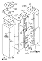
本発明にかかる電池パック10は、図1および図2にその全体的な構成を示す如く、部品取付面72を外周面の一部に備えた電池本体12と、その電池本体12の部品取付面72上に密着して配設され、電池本体12に対する通電状態を規制可能とする電子回路30と、その電子回路30の外周を少なくとも含み、電池本体12における外周の一部を限定して包囲する合成樹脂材からなる第1の保護部材16と、電池本体12の外周を包囲する第2の保護部材とを備えたことを特徴とする。
As shown in FIGS. 1 and 2, the
別の本発明にかかる電池パック10は、部品取付面72を外周面の一部に備えた電池本体12と、その電池本体12の部品取付面72上に密着して配設され、電池本体12に対する通電状態を規制可能とする電子回路30と、その電子回路30の外周を少なくとも含み、電池本体12における外周の一部を限定して包囲する合成樹脂材からなる保護部材16とを備え、電池本体12に電子回路30を一体成形してあることを特徴とする。
Another
電子回路30の回路基板26の幅が、部品取付面72の幅よりも小さい形態を採ることができる。部品取付面72は、電池本体12の側面、もしくは電池本体12の上端面18又は下端面86に設けることができる。
A configuration in which the width of the
本発明は、電子回路30を電池本体12上の1つの面に配設するとともに、その電子回路30の外周を少なくとも含んで、電池本体12における外周の一部を限定して保護部材16で包囲する様に構成したので、電子回路30に対する保護を有効に図りながら、電池パック外形の小型化、薄型化および軽量化が的確に図られる。
In the present invention, the
以下本発明にかかる電池パックを角型のリチウムイオン二次電池に実施した一例に基づいて説明するがこれに限らず、各種形状あるいはタイプの二次電池に対しても略同様に実施できることは勿論である。 Hereinafter, the battery pack according to the present invention will be described based on an example in which the prismatic lithium ion secondary battery is implemented. However, the present invention is not limited to this, and can be implemented substantially in the same manner for various types or types of secondary batteries. It is.
本発明にかかる電池パック10は、図1および図2にその全体的な構成を示す如く、電池本体12と、その電池本体12に対する充放電状態を規制するための制御を行うための図5に例示する電子回路30と、その電子回路30の周囲を覆う合成樹脂材からなる保護部材16とから構成される。
As shown in FIG. 1 and FIG. 2, the
電池本体12は、矩形筒状に形成されたリチウムイオン二次電池であり、その上端面18におけるやや偏心した位置から円筒状の正極20を突設するとともに、上端面18の全面を正極20の部分を残して絶縁板22で覆うことにより、電池本体12の外周におけるその他の面を正極20から絶縁して負極24を形成したものであって、以下においてその構成を詳述する電子回路30を介して複数回の充放電を可能としている。
The
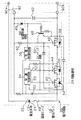
電子回路30は、回路基板26上に必要な電子回路部品28を配設することによって図5の様に構成されるものであって、電池本体12に対する通電路中に直列に介装されて通電時期を規制するスイッチング回路32と、充放電時における過充電、過放電あるいは過電流状態を検出して電池本体12の保護を図る保護制御回路34と、充電時に於ける電池本体12の端子電圧を設定値に維持する制御を行う充電制御回路36と、充電電圧が異常に高い場合に入力を絶って前記した保護制御回路34と充電制御回路36を保護する給電制御回路38と、電池本体12の過熱状態を検知して溶断する温度ヒューズ40とから構成される。
The
スイッチング回路32は、保護制御回路34によりオンオフ制御が行われる第1および第2スイッチング素子42・44と、充電制御回路36および給電制御回路38によりオンオフ制御が行われる第3および第4スイッチング素子46・48とから構成される。ここで第1〜第3スイッチング素子42・44・46はFETが使用されるとともに、そのソースとドレイン端子を互いに直列に接続したあと、電池本体12に対する負極24側の充放電回路中に直列に介装することにより、電池本体12に対する通電を直接的にオンオフ規制可能とする。
The
すなわち、第1スイッチング素子42は放電時期の規制用であって、そのゲート端子を保護制御回路34の放電制御端50に接続するとともに、ソース・ドレイン間に充電方向にダイオード54を接続することにより、そのスイッチング素子42のオンオフに拘らず充電は行えるが、保護制御回路34から放電オン信号が出力されたオン時にのみ放電が行える様にする。
In other words, the
これに対して第2スイッチング素子44は、そのゲート端子を保護制御回路34における充電制御端52に接続するとともに、ソース・ドレイン間に放電方向にダイオード56を接続することにより、そのスイッチング素子44のオンオフに拘らず放電は行えるが、保護制御回路34から充電オン信号が出力されてオン中に限定して充電が行えるようにしている。
On the other hand, the
なお上記した保護制御回路34における制御内容は従来と略同様であって、放電時における電池本体12の端子電圧が設定値を下回って低下することにより過放電が検出され、あるいは放電電流が設定値を超えることにより過電流が検出されると、第1スイッチング素子42をオフして放電を強制的に停止する。逆に、電池本体12の充電電圧が上限値を超えて上昇することによって過充電が検出され、あるいは充電電流が設定値を超えて過電流が検出されると、第2スイッチング素子44をオフして充電を強制的に停止することにより、電池本体12に対する電気的な保護を図っているが、その制御内容は限定されるものではない。
The contents of control in the
次に第3スイッチング素子46は、ソース・ドレイン間に放電方向にダイオード58を接続し、ゲート端子を抵抗60を介してプラス側の電源ラインに接続するとともに、ゲートとソース端子間にNPN型トランジスタからなる第4スイッチング素子48を備え、そのスイッチング素子48のベース端に充電制御回路36から出力される充電制御信号を印加する様にしている。かかる構成により、回路の外部から充電電圧が印加されるのと連動して抵抗60を介したオン信号の印加が行われて第3スイッチング素子46はオンされるが、充電制御回路36からオフ信号が出力されると第4スイッチング素子48をオンし、第3スイッチング素子46のゲート・ソース間を短絡してオフさせることにより、第3スイッチング素子46は第4スイッチング素子48を介して間接的にオンオフ制御される。
Next, in the
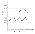
ここで充電制御回路36は、図6に例示するごとく、例えば4.08[V]と4.10[V]という様な比較的狭い範囲に第1の上限電圧VU1と下限電圧VL1とが設定され、その上限電圧VU1を超えると充電のオフ信号を出力し、下限電圧VL1を下回るとオフ信号を停止する実線で例示する様なオンオフ制御動作を行わせることにより、電池本体12の端子電圧を略4.09[V]に維持した状態でのパルス充電が行われる様にしている。一方、上記した保護制御回路34にあっても、例えば前記した第1の上限電圧VU1よりも十分に高い4.25[V]程度の第2の上限電圧VU2と、第1の下限電圧VL1よりやや低い4.05[V]程度の第2の下限電圧VL2を設定することにより、充電制御回路36の制御動作が不調となった場合にあっても、一点鎖線で例示する如く、保護制御回路34により充電制御動作が行えるようにしている。
Here, as illustrated in FIG. 6, the
また、第4スイッチング素子48のベース端とプラス極間に、電池本体12の充電電圧より十分に高い例えば第3の上限電圧VU3である6.8[V]程度の閾値を有するツエナーダイオード49を給電制御回路38として接続することにより、充電装置を間違えて極端に高い充電電圧を電池パック10に外部から印加した場合にあっても、ツエナーダイオード49を直ちにオンして第4スイッチング素子48をオンし、そのオン動作で第3スイッチング素子46をオフして電池パック10の入口側で通電を断ち、保護制御回路34および充電制御回路36が過電圧の印加により破損するのを未然に防止している。
Further, a Zener
更にまた電池本体12と直列に温度ヒューズ40が接続され、上記した全ての制御回路34・36・38の動作が不調で電池本体12が過充電あるいは過電流状態となった場合にあっても、電池本体12が設定温度を超えて上昇すると温度ヒューズ40が溶断し、電池本体12に対する最終的な保護を図っている。
Furthermore, even when the
なお各所に接続されているコンデンサ62は、例えば0.1[μF]程度の比較的大きいものが使用され、ノイズをバイパスして電子回路30が誤動作するのを防止するものである。
Note that the
また保護制御回路34と充電制御回路36はともに1チップの集積回路化されたものであるが、CMOS、NチャンネルMOSあるいはTTLといった様にその物理的あるいは電気的特性が異なるものを使用すれば、静電気や物理的ショックに起因して両制御回路34・36が同時に破損するのを防止することができる。
The
上記の様に構成された電子回路30は、部品取付面72に設定した電池本体12における1つの側面の幅よりその幅がやや小さい細帯状の回路基板26上に必要な電子回路部品28を半田付けしたあと、絶縁性を有する両面接着テープ64を介して対応する側面72上に接着固定される。
In the
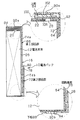
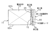
ところで電子回路部品28のうち、温度ヒューズ40は電池本体12の表面温度を直接検知する必要があるため、回路基板26上にコ字状の切欠き66を設け、その中に温度ヒューズ40を嵌め込む。更に、回路基板26の底面からの高さが小さい温度ヒューズ40の様な第1の回路部品群68と、高さが大きい集積回路チップの様な第2の回路部品群70とを、図3に例示する如く回路基板26の上下方向に分離して配置している。
By the way, in the
一方、上記した電子回路30を保護する第1の保護部材16は、図3および図4に示す如く、電池本体12に設定された部品取付面72の全体を覆う大きさの第1面74と、その第1面74と直交して電子回路30の長手方向両側を覆う第2面76a・76bとを備えることにより、第1の保護部材16の第1面74と第2面76および電池本体12の部品取付面72で包囲される空間78内に電子回路30を収納する様に構成する。
On the other hand, the first
更に、上記した電子回路基板26上における電子部品群の厚みに対応させて第1面74a・74bに段差80を設けることにより、電池パックとして構成した場合における長手方向への逆差しを防止している。一方第2面76は、図2および図4に示す如く、部品取付面72と左右方向に接する側面82と連続する様に形成することにより、電池本体12上に第1の保護部材16を取り付けた際に、その第1の保護部材16と電池本体12間に段差が生じることなく、電池本体12と同一平面状態で接合される様にしている。
Further, by providing a
本発明は基本的には、上記した如く電子回路部分のみを保護することで電池パックとしての最低限の保護は可能である。しかしながら本実施例にあっては更に、電池本体12の上端面18を覆う上板84と、下端面86を覆う下板88とをその端縁で前記した第1の保護部材16と結合したコ字形状に合成樹脂材で一体成形することにより、電子回路30から伸びる電極90のリード線92部分の保護をも図るとともに、第1の保護部材16の電池本体12に対する取り付けをより強固なものとしている。
Basically, the present invention can provide the minimum protection as a battery pack by protecting only the electronic circuit portion as described above. However, in this embodiment, the
ここで下板88は電池本体12の下端面86の全体を覆う薄板状であって、回路基板26側から伸びるマイナス側電極90bを電池本体12の下端面86との間で挟持して位置固定をするとともに、その中央部に設けた小径の開口94を通じ、マイナス側電極90bを電池パック10の外部に露出可能としている。
Here, the
更に上板84は、回路基板26の上縁側から伸びるプラス側電極90aのリード線92部分が電池本体12の負極24と接触するのを防止しながら、リード線92を電池本体12の正極20と接続し、更に電極90aを電池本体12の略中央に位置固定可能とすることによって、上板84の中央に設けた開口96を通じ、プラス側電極90aを電池パック10の外部に導出するようにしたものである。
Furthermore, the
かかる目的を達成するため、本実施例にあっては、電池本体12の上端面18側の絶縁板22上に接着固定したL字形状の取付板98と上板84とで図3の様に上ケース100を形成するとともに、その上ケース100内に更にコ字形状の中板102を配設することにより、その中板102の上面に電極90aを載せて上板84の下面間で挟持して端子台104とする一方、中板102の下面と取付板98間に形成した中ケース106で電極90aに至るリード線92部分を電池パック10の外部から隔離して保護している。
In order to achieve such an object, in this embodiment, an L-shaped mounting
上記の様に構成した電池パック10は、電子機器内に組み込む場合にはそのまま使用可能である。しかしながら本発明にあっては更に、少なくとも上下の開口94・96の部分を残してその周面部分を従来と略同様な熱収縮チューブの様な図示しない第2の保護部材で包囲することにより、取り外しを一般の需要者に行わせた場合にあっても、第1の保護部材16が不要に電池本体12から取り外されることが可及的に防止される様にしている。
The
その他、電子回路部分が更に小型に設計できる場合にあっては、電池本体12の側面に取りつけるのに代えて、上端面18または下端面86上に電子回路30およびそれを保護する保護部材を配設することができる。その場合は、電池本体12は円筒状のタイプでも実施できる。また、電子回路部品28を回路基板26を介して電池本体12に取りつけるのに代えて、電池本体12の周面上に直接取り付ける一方、回路基板26の構成を上記した第1の保護部材16と略同様なものとすることにより、第1の保護部材と回路基板とを兼用することもできる。
In addition, when the electronic circuit portion can be designed to be smaller, the
更に、上記のように1つの電池本体12に対して1つの第1の保護部材16を備えるのに代えて、複数の電池本体12における部品取付面72を横方向に並列して備えた状態で、その全体を1つの第1の保護部材16で覆うことも可能である。
Further, in place of providing one
10 電池パック
12 電池本体
16 第1の保護部材
18 電池本体の上端面
20 電池本体の正極
24 電池本体の負極
26 回路基板
28 電子回路部品
30 電子回路
32 スイッチング回路
34 保護制御回路
36 充電制御回路
38 給電制御回路
40 温度ヒューズ
42 第1スイッチング素子
44 第2スイッチング素子
46 第3スイッチング素子
48 第4スイッチング素子
64 両面接着テープ
68 第1回路部品群
70 第2回路部品群
72 部品取付面
74 第1保護部材の第1面
76 第1保護部材の第2面
80 第1保護部材の段差
82 電池本体の側面
84 第1保護部材の上板
86 電池本体の下端面
88 第1保護部材の下板
90 電極
92 リード線
98 取付板
DESCRIPTION OF
Claims (5)
該電池本体の部品取付面上に密着して配設され、該電池本体に対する通電状態を規制可能とする電子回路と、
該電子回路の外周を少なくとも含んで前記電池本体における外周の一部を限定して包囲する合成樹脂材からなる第1の保護部材と、
前記電池本体の外周を包囲する第2の保護部材とを備えた電池パック。 A battery body having a part mounting surface on a part of the outer peripheral surface;
An electronic circuit that is disposed in close contact with a part mounting surface of the battery body, and that can regulate an energization state of the battery body;
A first protective member made of a synthetic resin material that includes at least the outer periphery of the electronic circuit and surrounds the battery body by limiting a part of the outer periphery;
A battery pack comprising: a second protective member surrounding an outer periphery of the battery body.
該電池本体の部品取付面上に密着して配設され、該電池本体に対する通電状態を規制可能とする電子回路と、
該電子回路の外周を少なくとも含んで前記電池本体における外周の一部を限定して包囲する合成樹脂材からなる保護部材とを備え、
前記電池本体に前記電子回路を一体成形してある電池パック。 A battery body having a part mounting surface on a part of the outer peripheral surface;
An electronic circuit that is disposed in close contact with a part mounting surface of the battery body, and that can regulate an energization state of the battery body;
A protective member made of a synthetic resin material that includes at least the outer periphery of the electronic circuit and surrounds the battery body in a limited manner.
A battery pack in which the electronic circuit is integrally formed in the battery body.
Priority Applications (5)
| Application Number | Priority Date | Filing Date | Title |
|---|---|---|---|
| JP31269096A JP3531090B2 (en) | 1996-11-07 | 1996-11-07 | Battery pack |
| US08/966,030 US5912092A (en) | 1996-11-07 | 1997-11-07 | Battery package |
| JP2002350964A JP4024660B2 (en) | 1996-11-07 | 2002-12-03 | Battery pack |
| JP2007225681A JP4172719B2 (en) | 1996-11-07 | 2007-08-31 | Battery pack |
| JP2008031129A JP4172721B2 (en) | 1996-11-07 | 2008-02-12 | Battery pack |
Applications Claiming Priority (4)
| Application Number | Priority Date | Filing Date | Title |
|---|---|---|---|
| JP31269096A JP3531090B2 (en) | 1996-11-07 | 1996-11-07 | Battery pack |
| JP2002350964A JP4024660B2 (en) | 1996-11-07 | 2002-12-03 | Battery pack |
| JP2007225681A JP4172719B2 (en) | 1996-11-07 | 2007-08-31 | Battery pack |
| JP2008031129A JP4172721B2 (en) | 1996-11-07 | 2008-02-12 | Battery pack |
Related Parent Applications (1)
| Application Number | Title | Priority Date | Filing Date |
|---|---|---|---|
| JP2002350964A Division JP4024660B2 (en) | 1996-11-07 | 2002-12-03 | Battery pack |
Related Child Applications (1)
| Application Number | Title | Priority Date | Filing Date |
|---|---|---|---|
| JP2008031129A Division JP4172721B2 (en) | 1996-11-07 | 2008-02-12 | Battery pack |
Publications (2)
| Publication Number | Publication Date |
|---|---|
| JP2007311368A true JP2007311368A (en) | 2007-11-29 |
| JP4172719B2 JP4172719B2 (en) | 2008-10-29 |
Family
ID=51453524
Family Applications (4)
| Application Number | Title | Priority Date | Filing Date |
|---|---|---|---|
| JP31269096A Expired - Lifetime JP3531090B2 (en) | 1996-11-07 | 1996-11-07 | Battery pack |
| JP2002350964A Expired - Lifetime JP4024660B2 (en) | 1996-11-07 | 2002-12-03 | Battery pack |
| JP2007225681A Expired - Lifetime JP4172719B2 (en) | 1996-11-07 | 2007-08-31 | Battery pack |
| JP2008031129A Expired - Lifetime JP4172721B2 (en) | 1996-11-07 | 2008-02-12 | Battery pack |
Family Applications Before (2)
| Application Number | Title | Priority Date | Filing Date |
|---|---|---|---|
| JP31269096A Expired - Lifetime JP3531090B2 (en) | 1996-11-07 | 1996-11-07 | Battery pack |
| JP2002350964A Expired - Lifetime JP4024660B2 (en) | 1996-11-07 | 2002-12-03 | Battery pack |
Family Applications After (1)
| Application Number | Title | Priority Date | Filing Date |
|---|---|---|---|
| JP2008031129A Expired - Lifetime JP4172721B2 (en) | 1996-11-07 | 2008-02-12 | Battery pack |
Country Status (2)
| Country | Link |
|---|---|
| US (1) | US5912092A (en) |
| JP (4) | JP3531090B2 (en) |
Cited By (2)
| Publication number | Priority date | Publication date | Assignee | Title |
|---|---|---|---|---|
| JP2009245919A (en) * | 2008-03-28 | 2009-10-22 | Samsung Sdi Co Ltd | Protective circuit board and battery pack equipped with same |
| FR2981536A1 (en) * | 2011-10-12 | 2013-04-19 | Bilal Manai | Method for forming battery pack used in e.g. mobile phone, involves connecting printed circuit board against upper face of battery, and performing spot welding across through-opening from face of electronic board opposite to face of battery |
Families Citing this family (35)
| Publication number | Priority date | Publication date | Assignee | Title |
|---|---|---|---|---|
| JP3507333B2 (en) * | 1998-05-28 | 2004-03-15 | ローム株式会社 | Protection circuit and battery pack for rechargeable battery |
| JP3454748B2 (en) * | 1999-02-26 | 2003-10-06 | 三洋電機株式会社 | Battery pack |
| US6979502B1 (en) * | 1999-06-21 | 2005-12-27 | Board Of Trustees Of The University Of Illinois | Battery having a housing for electronic circuitry |
| EP1250720B1 (en) * | 1999-06-21 | 2006-05-24 | The Board Of Trustees Of The University Of Illinois | Battery having a housing for electronic circuitry |
| JP3638102B2 (en) * | 1999-09-30 | 2005-04-13 | Necトーキン栃木株式会社 | Battery pack |
| AU3268501A (en) * | 1999-11-12 | 2001-06-06 | Surecall, Llc | Holder for securing one or more batteries |
| JP3696559B2 (en) * | 2002-02-26 | 2005-09-21 | 京セラ株式会社 | battery |
| JP4079017B2 (en) * | 2003-03-18 | 2008-04-23 | 松下電器産業株式会社 | Remote control transmitter |
| JP3873966B2 (en) * | 2003-10-24 | 2007-01-31 | ソニー株式会社 | battery pack |
| KR100571272B1 (en) * | 2004-11-18 | 2006-04-13 | 삼성에스디아이 주식회사 | Can-type secondary battery and its formation method |
| KR100891079B1 (en) * | 2005-02-07 | 2009-03-30 | 주식회사 엘지화학 | Battery Cartridge Connection System for Battery Module |
| KR100801852B1 (en) * | 2005-04-21 | 2008-02-11 | 주식회사 엘지화학 | Battery pack protection device and method |
| KR100839785B1 (en) * | 2005-12-29 | 2008-06-19 | 삼성에스디아이 주식회사 | Secondary Battery and Formation Method |
| JP5064776B2 (en) * | 2006-12-07 | 2012-10-31 | 三洋電機株式会社 | Pack battery |
| KR100870362B1 (en) * | 2007-03-15 | 2008-11-25 | 삼성에스디아이 주식회사 | Protective Circuit Board for Secondary Battery and Secondary Battery Using the Same |
| KR100922468B1 (en) * | 2007-09-21 | 2009-10-21 | 삼성에스디아이 주식회사 | Battery pack |
| KR100876266B1 (en) * | 2007-09-28 | 2008-12-26 | 삼성에스디아이 주식회사 | Secondary battery |
| JP4297452B2 (en) * | 2007-12-27 | 2009-07-15 | 株式会社リコー | Charge / discharge protection circuit |
| US8334063B2 (en) | 2008-09-22 | 2012-12-18 | Samsung Sdi Co., Ltd. | Secondary battery |
| KR101016852B1 (en) * | 2008-12-11 | 2011-02-22 | 삼성에스디아이 주식회사 | Secondary battery |
| JP2010258138A (en) * | 2009-04-23 | 2010-11-11 | Panasonic Corp | Battery unit |
| KR102112970B1 (en) | 2009-05-18 | 2020-05-19 | 젠썸 인코포레이티드 | Battery thermal management system |
| US8580415B2 (en) * | 2010-12-03 | 2013-11-12 | Nokia Corporation | Method and apparatus for an electrical interface |
| KR101222386B1 (en) * | 2011-01-20 | 2013-01-16 | 삼성에스디아이 주식회사 | Battery Pack |
| DE112012002935T5 (en) | 2011-07-11 | 2014-05-15 | Gentherm Inc. | Thermoelectric based thermal management of electrical devices |
| WO2014110524A1 (en) | 2013-01-14 | 2014-07-17 | Gentherm Incorporated | Thermoelectric-based thermal management of electrical devices |
| US10270141B2 (en) | 2013-01-30 | 2019-04-23 | Gentherm Incorporated | Thermoelectric-based thermal management system |
| JP5850017B2 (en) | 2013-10-15 | 2016-02-03 | 株式会社デンソー | Battery monitoring device |
| CN106030898B (en) | 2013-10-29 | 2019-04-05 | 詹思姆公司 | Battery Thermal Management Using Thermoelectrics |
| CN106717139B (en) | 2014-09-12 | 2019-07-12 | 詹思姆公司 | Graphite thermoelectric and/or resistive thermal management systems and methods |
| US10283817B2 (en) | 2015-02-23 | 2019-05-07 | Black & Decker, Inc. | Battery charger and method of charging a battery |
| CN104868075B (en) * | 2015-05-25 | 2017-04-05 | 中国民航大学 | A kind of charging batteries of electric automobile quick-replaceable battery component |
| CN107742685B (en) * | 2017-10-12 | 2023-12-05 | 苏州达方电子有限公司 | Battery module |
| CN121230238A (en) | 2018-11-30 | 2025-12-30 | 金瑟姆股份公司 | Thermoelectric control systems and methods |
| US11152557B2 (en) | 2019-02-20 | 2021-10-19 | Gentherm Incorporated | Thermoelectric module with integrated printed circuit board |
Family Cites Families (3)
| Publication number | Priority date | Publication date | Assignee | Title |
|---|---|---|---|---|
| US5726859A (en) * | 1995-07-26 | 1998-03-10 | Dell Usa, L.P. | Circuit board component retainer and extractor |
| US5693431A (en) * | 1995-08-08 | 1997-12-02 | Selfcharge, Inc. | Rechargeable battery pack for mobile telephones |
| US5607791A (en) * | 1996-07-08 | 1997-03-04 | Motorola, Inc | Battery interface structure for an electrical device |
-
1996
- 1996-11-07 JP JP31269096A patent/JP3531090B2/en not_active Expired - Lifetime
-
1997
- 1997-11-07 US US08/966,030 patent/US5912092A/en not_active Expired - Lifetime
-
2002
- 2002-12-03 JP JP2002350964A patent/JP4024660B2/en not_active Expired - Lifetime
-
2007
- 2007-08-31 JP JP2007225681A patent/JP4172719B2/en not_active Expired - Lifetime
-
2008
- 2008-02-12 JP JP2008031129A patent/JP4172721B2/en not_active Expired - Lifetime
Cited By (3)
| Publication number | Priority date | Publication date | Assignee | Title |
|---|---|---|---|---|
| JP2009245919A (en) * | 2008-03-28 | 2009-10-22 | Samsung Sdi Co Ltd | Protective circuit board and battery pack equipped with same |
| US8900741B2 (en) | 2008-03-28 | 2014-12-02 | Samsung Sdi Co., Ltd. | Protective circuit board and battery pack using the same |
| FR2981536A1 (en) * | 2011-10-12 | 2013-04-19 | Bilal Manai | Method for forming battery pack used in e.g. mobile phone, involves connecting printed circuit board against upper face of battery, and performing spot welding across through-opening from face of electronic board opposite to face of battery |
Also Published As
| Publication number | Publication date |
|---|---|
| JP4172721B2 (en) | 2008-10-29 |
| US5912092A (en) | 1999-06-15 |
| JP4172719B2 (en) | 2008-10-29 |
| JP2008166292A (en) | 2008-07-17 |
| JP2003157814A (en) | 2003-05-30 |
| JP3531090B2 (en) | 2004-05-24 |
| JPH10144270A (en) | 1998-05-29 |
| JP4024660B2 (en) | 2007-12-19 |
Similar Documents
| Publication | Publication Date | Title |
|---|---|---|
| JP4172721B2 (en) | Battery pack | |
| US7592778B2 (en) | Battery protection IC chip | |
| US5304915A (en) | Overcharge preventing device and overdischarge preventing device for a secondary battery | |
| EP1181760B1 (en) | Devices and methods for protection of rechargeable elements | |
| EP0982826B1 (en) | Battery protection circuit and electronic device | |
| US7898216B2 (en) | Rechargeable battery device having a protection circuit for protecting from overcharge and overdischarge | |
| JP2000223160A (en) | Power supply | |
| JP2009183141A (en) | Apparatus and method for protection of rechargeable elements | |
| KR101729730B1 (en) | Apparatus for protecting battery from overcurrent | |
| KR20110132970A (en) | Battery protection module | |
| JP2001112182A (en) | Secondary battery protection circuit | |
| US6580250B1 (en) | Monolithic battery protection circuit | |
| JP2004006524A (en) | COB module with temperature sensor | |
| EP1339154A1 (en) | Monolithic battery protection circuit | |
| KR101028784B1 (en) | Semiconductor integrated circuit | |
| JP3634128B2 (en) | Battery pack | |
| JPH09308114A (en) | Charge and discharge controller for battery | |
| KR100292608B1 (en) | Battery pack | |
| EP2768044A1 (en) | Battery pack | |
| JPH10150721A (en) | Protective circuit for secondary battery | |
| KR101170117B1 (en) | one chip structure of battery protection circuits | |
| JP2003070153A (en) | Method for preventing overheat of secondary battery pack | |
| US12347835B2 (en) | All-solid-state battery module, electronic device, and method for manufacturing all-solid-state battery module | |
| JP2003189480A (en) | Protective circuit of secondary battery | |
| US12088083B2 (en) | Protective circuit equipped with a reflux circuit and a switching circuit and energy storage apparatus containing the protective circuit |
Legal Events
| Date | Code | Title | Description |
|---|---|---|---|
| A621 | Written request for application examination |
Free format text: JAPANESE INTERMEDIATE CODE: A621 Effective date: 20070831 |
|
| A131 | Notification of reasons for refusal |
Free format text: JAPANESE INTERMEDIATE CODE: A132 Effective date: 20071212 |
|
| A521 | Request for written amendment filed |
Free format text: JAPANESE INTERMEDIATE CODE: A523 Effective date: 20080207 |
|
| A521 | Request for written amendment filed |
Free format text: JAPANESE INTERMEDIATE CODE: A523 Effective date: 20080212 |
|
| A131 | Notification of reasons for refusal |
Free format text: JAPANESE INTERMEDIATE CODE: A132 Effective date: 20080514 |
|
| TRDD | Decision of grant or rejection written | ||
| A01 | Written decision to grant a patent or to grant a registration (utility model) |
Free format text: JAPANESE INTERMEDIATE CODE: A01 Effective date: 20080806 |
|
| A01 | Written decision to grant a patent or to grant a registration (utility model) |
Free format text: JAPANESE INTERMEDIATE CODE: A01 |
|
| A61 | First payment of annual fees (during grant procedure) |
Free format text: JAPANESE INTERMEDIATE CODE: A61 Effective date: 20080808 |
|
| R150 | Certificate of patent or registration of utility model |
Free format text: JAPANESE INTERMEDIATE CODE: R150 |
|
| FPAY | Renewal fee payment (event date is renewal date of database) |
Free format text: PAYMENT UNTIL: 20110822 Year of fee payment: 3 |
|
| FPAY | Renewal fee payment (event date is renewal date of database) |
Free format text: PAYMENT UNTIL: 20110822 Year of fee payment: 3 |
|
| FPAY | Renewal fee payment (event date is renewal date of database) |
Free format text: PAYMENT UNTIL: 20120822 Year of fee payment: 4 |
|
| FPAY | Renewal fee payment (event date is renewal date of database) |
Free format text: PAYMENT UNTIL: 20120822 Year of fee payment: 4 |
|
| S111 | Request for change of ownership or part of ownership |
Free format text: JAPANESE INTERMEDIATE CODE: R313111 |
|
| R350 | Written notification of registration of transfer |
Free format text: JAPANESE INTERMEDIATE CODE: R350 |
|
| FPAY | Renewal fee payment (event date is renewal date of database) |
Free format text: PAYMENT UNTIL: 20120822 Year of fee payment: 4 |
|
| FPAY | Renewal fee payment (event date is renewal date of database) |
Free format text: PAYMENT UNTIL: 20120822 Year of fee payment: 4 |
|
| FPAY | Renewal fee payment (event date is renewal date of database) |
Free format text: PAYMENT UNTIL: 20120822 Year of fee payment: 4 |
|
| FPAY | Renewal fee payment (event date is renewal date of database) |
Free format text: PAYMENT UNTIL: 20120822 Year of fee payment: 4 |
|
| FPAY | Renewal fee payment (event date is renewal date of database) |
Free format text: PAYMENT UNTIL: 20120822 Year of fee payment: 4 |
|
| FPAY | Renewal fee payment (event date is renewal date of database) |
Free format text: PAYMENT UNTIL: 20130822 Year of fee payment: 5 |
|
| S111 | Request for change of ownership or part of ownership |
Free format text: JAPANESE INTERMEDIATE CODE: R313111 |
|
| FPAY | Renewal fee payment (event date is renewal date of database) |
Free format text: PAYMENT UNTIL: 20130822 Year of fee payment: 5 |
|
| R350 | Written notification of registration of transfer |
Free format text: JAPANESE INTERMEDIATE CODE: R350 |
|
| FPAY | Renewal fee payment (event date is renewal date of database) |
Free format text: PAYMENT UNTIL: 20130822 Year of fee payment: 5 |
|
| FPAY | Renewal fee payment (event date is renewal date of database) |
Free format text: PAYMENT UNTIL: 20130822 Year of fee payment: 5 |
|
| R250 | Receipt of annual fees |
Free format text: JAPANESE INTERMEDIATE CODE: R250 |
|
| R250 | Receipt of annual fees |
Free format text: JAPANESE INTERMEDIATE CODE: R250 |
|
| R250 | Receipt of annual fees |
Free format text: JAPANESE INTERMEDIATE CODE: R250 |
|
| R250 | Receipt of annual fees |
Free format text: JAPANESE INTERMEDIATE CODE: R250 |
|
| EXPY | Cancellation because of completion of term |