JP2007308094A - Curtain airbag device - Google Patents
Curtain airbag device Download PDFInfo
- Publication number
- JP2007308094A JP2007308094A JP2006141499A JP2006141499A JP2007308094A JP 2007308094 A JP2007308094 A JP 2007308094A JP 2006141499 A JP2006141499 A JP 2006141499A JP 2006141499 A JP2006141499 A JP 2006141499A JP 2007308094 A JP2007308094 A JP 2007308094A
- Authority
- JP
- Japan
- Prior art keywords
- curtain airbag
- gas
- airbag
- coupling portion
- folded
- Prior art date
- Legal status (The legal status is an assumption and is not a legal conclusion. Google has not performed a legal analysis and makes no representation as to the accuracy of the status listed.)
- Granted
Links
Images


Classifications
-
- B—PERFORMING OPERATIONS; TRANSPORTING
- B60—VEHICLES IN GENERAL
- B60R—VEHICLES, VEHICLE FITTINGS, OR VEHICLE PARTS, NOT OTHERWISE PROVIDED FOR
- B60R21/00—Arrangements or fittings on vehicles for protecting or preventing injuries to occupants or pedestrians in case of accidents or other traffic risks
- B60R21/02—Occupant safety arrangements or fittings, e.g. crash pads
- B60R21/16—Inflatable occupant restraints or confinements designed to inflate upon impact or impending impact, e.g. air bags
- B60R21/23—Inflatable members
- B60R21/237—Inflatable members characterised by the way they are folded
-
- B—PERFORMING OPERATIONS; TRANSPORTING
- B60—VEHICLES IN GENERAL
- B60R—VEHICLES, VEHICLE FITTINGS, OR VEHICLE PARTS, NOT OTHERWISE PROVIDED FOR
- B60R21/00—Arrangements or fittings on vehicles for protecting or preventing injuries to occupants or pedestrians in case of accidents or other traffic risks
- B60R21/02—Occupant safety arrangements or fittings, e.g. crash pads
- B60R21/16—Inflatable occupant restraints or confinements designed to inflate upon impact or impending impact, e.g. air bags
- B60R21/23—Inflatable members
- B60R21/231—Inflatable members characterised by their shape, construction or spatial configuration
- B60R21/232—Curtain-type airbags deploying mainly in a vertical direction from their top edge
Abstract
Description
本発明は、自動車の側面衝突(側突)時やロールオーバー(横転)時にサイドドアの窓等に沿って膨張するカーテンエアバッグ装置に関する。 The present invention relates to a curtain airbag device that inflates along a window or the like of a side door at the time of a side collision (side collision) or rollover (rollover) of an automobile.
ルーフサイドレール部に格納されたエアバッグに、側突又はロールオーバー検出時にインフレーターから膨張用ガスが導入されて車内側に展開することで、乗員の頭部を保護するカーテンエアバッグ装置としては、例えば米国特許第6758490号公報(US 6,758,490 B2)に記載されているように、車外側に位置するロール部(rolled portion)と車内側に位置する折り返し部(fold portion)を有する構成のものが知られている(特許文献1のFig.4a参照)。
このように従来のカーテンエアバッグ装置は、図3に示すようにその上縁部の取付部はルーフサイドレール部aに固定され、車外側に一度折り返して車内側にロール折りされた状態で前記ルーフサイドレール部aに格納されている。一度折り返している部分を「+1」と呼び、ロール部rが車外側にあり、「+1」の折り返し部fが車内側にあるので、図3のようなカーテンエアバッグは、「内ロール+1」折りされたカーテンエアバッグと呼ばれている。 Thus, as shown in FIG. 3, the conventional curtain airbag device has its upper edge mounting portion fixed to the roof side rail portion a, folded once on the outside of the vehicle, and roll-folded on the inside of the vehicle. It is stored in the roof side rail part a. Once folded back and a portion is referred to as "+1", the roll portion r is located outside of the vehicle, since the folded portion f is in the car in the side of the "+ 1", the curtain airbag shown in FIG. 3, "inner roll +1 "It is called a folded curtain airbag.
従来の「内ロール+1」折りされたカーテンエアバッグでは、「+1」の折り返し部の寸法管理でエアバッグの展開方向をコントロールしていたが、「+1」の折り返し部の寸法を管理するだけでは、カーテンエアバッグの展開方向に影響を与えてしまい、エアバッグ展開時にルーフサイドレール部やヘッドライナー等のガーニッシュ(GN)類との干渉性・攻撃性が問題となり、理想的な展開方向との両立が難しかった。 In the conventional curtain airbag folded “inner roll + 1”, the deployment direction of the airbag was controlled by the dimension management of the “+1” folded part, but only by managing the dimension of the “+1” folded part. This will affect the deployment direction of the curtain airbag, causing interference and aggression with garnishes (GN) such as roof side rails and head liners when the airbag is deployed. It was difficult to balance.
本発明は、上記の課題を解決するものであり、カーテンエアバッグのガーニッシュ(GN)回りの干渉性・攻撃性をなくし、カーテンエアバッグのGN回り以外の部分は、サイドドアの窓ガラスに沿って適切に展開させる、といった展開方向のコントロールが容易なカーテンエアバッグ装置を提供することを目的とする。 The present invention solves the above-mentioned problems, eliminates the interference and aggression around the garnish (GN) of the curtain airbag, and the portion other than the GN around the curtain airbag is along the window glass of the side door. It is an object of the present invention to provide a curtain airbag device in which the deployment direction can be easily controlled by appropriately deploying.
そのために本発明のカーテンエアバッグ装置は、ルーフサイドレール部に格納されたエアバッグに、側突又はロールオーバー検出時にインフレーターから膨張用ガスが導入されて車内側に展開することで、乗員の頭部を保護するカーテンエアバッグ装置であって、
前記エアバッグは、その上方長手方向に延びるガス供給路と、前記ガス供給路から下方に向けて膨張用ガスが導入される複数のセルとを有するとともに、車外側に一度折り返して車内側にロール折りされた状態で、その上縁部が前記ルーフサイドレール部に固定され、さらに前記ガス供給路から前記各セルに膨張用ガスを導入するスロット部の形状を上方が広く下方が絞られた略逆三角形状としたことを特徴とする。
そして、前記スロット部は、着座した乗員頭部に対応する領域に配置し、ピラーガーニッシュに対応する領域には配置しないようにすることが好ましい。
For this purpose, the curtain airbag device of the present invention introduces an inflating gas from an inflator to the airbag stored in the roof side rail portion when a side collision or rollover is detected and deploys it to the passenger's head. A curtain airbag device for protecting a part,
The airbag has a gas supply path extending in the upper longitudinal direction thereof and a plurality of cells into which inflation gas is introduced downward from the gas supply path, and is folded back to the vehicle exterior side and rolled to the vehicle interior side. In the folded state, the upper edge portion is fixed to the roof side rail portion, and the shape of the slot portion for introducing the expansion gas from the gas supply path to each cell is broadened upward and the lower portion is narrowed down. It is characterized by an inverted triangle shape.
And it is preferable to arrange | position the said slot part in the area | region corresponding to the seated passenger | crew head, and not to arrange | position in the area | region corresponding to a pillar garnish.
本発明のカーテンエアバッグ装置は、「+1」の折り返し部の寸法管理とセルパターンの組み合わせによりエアバッグの展開方向をコントロールできるので、ルーフサイドレール部やヘッドライナー等のガーニッシュ(GN)類との干渉性・攻撃性と理想的な展開方向の両立を可能とする。 The curtain airbag device of the present invention can control the deployment direction of the airbag by combining the dimension management of the folded portion of “+1” and the cell pattern, so that it can be used with garnishes (GN) such as roof side rails and head liners. It enables coexistence / aggression and ideal deployment direction.
本発明の実施の形態の一例を図面を参照して詳細に説明する。
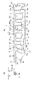
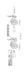
図1(A)は本発明の実施の形態に係るカーテンエアバッグ装置の正面図、図1(B)は「内ロール+1」折りされた状態の図1(A)のカーテンエアバッグ装置のスロット部の断面図、図2は図1のスロット部の展開初期の膨張状態を説明する断面図、図3はカーテンエアバッグの「内ロール+1」折りを説明する断面図である。
An example of an embodiment of the present invention will be described in detail with reference to the drawings.
FIG. 1A is a front view of a curtain airbag device according to an embodiment of the present invention, and FIG. 1B is a slot of the curtain airbag device of FIG. 2 is a cross-sectional view for explaining the inflated state of the slot portion in FIG. 1 at the initial stage of deployment, and FIG. 3 is a cross-sectional view for explaining the “inner roll + 1” folding of the curtain airbag.
カーテンエアバッグ装置Mのエアバッグ10は、「内ロール+1」折りにて折り畳まれた状態で、例えば自動車のフロントピラーからリアピラーにかけてルーフサイドレール部に沿って格納され、自動車の側突又はロールオーバー検出時にインフレーターから膨張用ガスが導入されて、車室側面に沿って車内側にカーテン状に膨張展開し、自動車内の前席及び後席の乗員の頭部を受けとめて頭部を保護し、あるいは窓ガラスが割れて乗員が車外に投げ出されることを防止する。
The
前記エアバッグ10は、膨張展開完了時に車室側面と車室内とにそれぞれ面する内側シートと外側シートを重ね合わせ、これらシートを線状結合部及び環状結合部によって結合することにより、その上方長手方向に延びるガス供給路20、前記ガス供給路20から下方に向けて膨張用ガスが導入される複数のセルC1,C2、及び非膨張部N1,N2が形成される。
When the
前記ガス供給路の一方の入口21は、前記エアバッグ10上方のリアピラー側の端部に形成され、前記前記ガス供給路20の他方の入口22は、前記エアバッグ10上方のフロントピラー側の端部に形成される。上記一方の入口21および他方の入口22には、それぞれガス供給源であるインフレータ(図示せず)に接続されている。
One
線状結合部11は、前記エアバッグ10を略周回するように配設される。前記他方の入口22側に配設された線状結合部12は、前記線状結合部11の入口22側の部分とともにスロット部S1を形成する。このスロット部S1は前記ガス供給路20からセルC1へ膨張ガスを導入する部分であり、このスロット部S1の形状は前記線状結合部11と前記線状結合部12により構成され、その形状は上方が広く下方が絞られた略逆三角形状をなしている。
The
いわゆる「内ロール+1」折りされたエアバッグ10は、膨張展開時の初期は、スロット部S1が略逆三角形状をなして絞られている(絞りを形成している)ため、下方のセルへの膨張用ガスの導入が制限される。この結果、主に前記スロット部S1の折り返し部S1−fが膨張してロール部S1−rを強く車外側に押し付け(図2参照)、その後サイドドアの窓ガラス沿いに前記ロール部S1−rが展開する。
The so-called “inner roll + 1” folded
前記線状結合部12は前記線状結合部11下方から上方向に延設され略「ク」字形をなし、その内側にセルC1を形成し、その端部は環状結合部12aに連なっており、環状結合部12aは線状結合部12の端部を補強している。
The
前記線状結合部12に隣接して略J字形の線状結合部13が配設され、略「ロ」字形の線状連結部14は、この線状結合部13に連なり、前記線状結合部14の内側には非膨張部N1が形成される。前記線状結合部13の端部は環状結合部13aに連なっており、環状結合部13aは線状結合部13の端部を補強している。
A substantially J-shaped
前記線状結合部14と隣接して略7字形の線状結合部15が配設される。前記線状結合部15は、前記線状結合部11下方から上方向に延設され、その端部は環状結合部15aに連なっており、環状結合部15aは線状結合部15の端部を補強している。
A substantially 7-shaped
前記線状結合部15は、線状結合部16とともにセルC2を形成する。前記線状結合部16の両端は環状結合部16a,16bに連なっている。前記環状結合部15aと前記環状結合部16aの隙間から膨張用ガスが前記セルC2に流れ込む。
The
前記線状結合部15は、前記線状結合部14とともにスロット部S2を形成する。このスロット部S2は前記ガス供給路20からセルC2へ膨張ガスを導入する部分であり、このスロット部S2の形状は前記線状結合部14と前記線状結合部15により構成され、その形状は上方が広く下方が絞られた略逆三角形状をなしている。
The
いわゆる「内ロール+1」折りされたエアバッグ10は、膨張展開時の初期は、図2に示すように前記スロット部S2の折り返し部S2−fに膨張ガス用が導入されるので、ロール部S2−rが強く車外側に押し付けられ、その後サイドドアの窓ガラス沿いに前記ロール部S2−rが展開する。
Since the
前記線状結合部15に隣接して略J字形の線状結合部17が配設され、略「ロ」字形の線状連結部18は、この線状結合部17に連なり、前記線状結合部18の内側に非膨張部N2が形成される。前記線状結合部17の端部は環状結合部17aに連なっており、環状結合部17aは線状結合部17の端部を補強している。
A substantially J-shaped
前記線状連結部18に隣接して線状結合部19が配設される。前記線状結合部19の両端は環状結合部19a,19bに連なっている。また、前記線状結合部11の前記入口21近傍には環状結合部11aが形成される。
A
各線状結合部11〜19及び各環状結合部11a〜19a,16b,19bは、前記内側シートと外側シート同士を気密に結合し、なおかつ前記エアバッグ10の内圧が設計上限圧力まで上昇しても前記内側シートと外側シート同士が離反しないような強固な結合手段(例えば、強度の高い縫糸による縫合や、接着力の高い接着剤による接着、あるいは溶着)により形成される。
Even if each linear coupling part 11-19 and each
前記エアバッグ10を周回するように配設された線状結合部11を囲むように膨張用ガスを流入させない上周縁部50と下周縁部51と有する。前記上周縁部50の上縁側には、前記エアバッグ10をルーフサイドレール部に取り付けるための複数の取付部53が形成されている。また、前記下周縁51のフロントピラー側には、クランプ54が固着され、自動車内の所定の接続部(フロントピラー下部)に接続される。
It has the upper
このように構成されたエアバッグ10を有するカーテンエアバッグ装置Mは、側突又はロールオーバー検出時にインフレーターから膨張用ガスがガス供給路20の入口21から導入され、膨張展開時の初期は、スロット部S1(S2)の折り返し部S1−f(S2−f)に膨張用ガスが導入されるので、ロール部S1−rが強く車外側に押し付けられ、その後セルC1、セルC2等に膨張用ガスが導入されるので、サイドドアの窓ガラス沿いに前記ロール部S1−r(S2−r)が展開し、カーテン状に下方へ広がる。従って、乗員の頭部Hとピラーや窓ガラスとの隙間が狭くても、その間にカーテンエアバッグをスムーズに展開させることができる。一方、ピラーガーニッシュGNに対応する領域では、乗員の頭部Hに対応する領域に比べて車室内側に向かってカーテンエアバッグが展開されることから、カーテンエアバッグのピラーガーニッシュ上端部への引っ掛かりやピラーガーニッシュの飛散を抑制することが可能である(図4参照)。この結果、側突時やロールオーバー時において、乗員の頭部Hを有効に保護することができると共にカーテンエアバッグのピラーガーニッシュGNへの引っ掛かりやピラーガーニッシュの飛散を抑制することができる。
In the curtain airbag apparatus M having the
以上、本発明の実施の形態について説明したが、本発明はこれらに何ら限定されるものでもなく、特許請求の範囲に示された技術的思想において変更可能である。 As mentioned above, although embodiment of this invention was described, this invention is not limited to these at all, and can be changed in the technical idea shown by the claim.
10 エアバッグ
11〜19 線状結合部
11a〜19a,16b,19b 環状結合部
20 ガス供給路
21 一方の入口
22 他方の入口
C1,C2セル
S1,S2 スロット部
S1−f,S2−f 折り返し部
S1−r,S2−r ロール部
N1,N2 非膨張部
GN ガーニッシュ
H 乗員の頭部
10
Claims (2)
前記エアバッグは、その上方長手方向に延びるガス供給路と、前記ガス供給路から下方に向けて膨張用ガスが導入される複数のセルとを有するとともに、車外側に一度折り返して車内側にロール折りされた状態で、その上縁部が前記ルーフサイドレール部に固定され、さらに前記ガス供給路から前記各セルに膨張用ガスを導入するスロット部の形状を上方が広く下方が絞られた略逆三角形状としたことを特徴とするカーテンエアバッグ装置。 A curtain airbag device for protecting an occupant's head by introducing an inflating gas from an inflator to a airbag stored in a roof side rail portion when a side collision or rollover is detected and deploying the airbag to the inside of the vehicle. ,
The airbag has a gas supply path extending in the upper longitudinal direction thereof and a plurality of cells into which inflation gas is introduced downward from the gas supply path, and is folded back to the vehicle exterior side and rolled to the vehicle interior side. In the folded state, the upper edge portion is fixed to the roof side rail portion, and the shape of the slot portion for introducing the expansion gas from the gas supply path to each cell is broadened upward and the lower portion is narrowed down. A curtain airbag device characterized by having an inverted triangular shape.
2. The curtain airbag device according to claim 1, wherein the slot portion is disposed in a region corresponding to a seated occupant head and is not disposed in a region corresponding to a pillar garnish.
Priority Applications (2)
| Application Number | Priority Date | Filing Date | Title |
|---|---|---|---|
| JP2006141499A JP4850579B2 (en) | 2006-05-22 | 2006-05-22 | Curtain airbag device |
| PCT/JP2007/060347 WO2007136027A1 (en) | 2006-05-22 | 2007-05-21 | Curtain airbag system |
Applications Claiming Priority (1)
| Application Number | Priority Date | Filing Date | Title |
|---|---|---|---|
| JP2006141499A JP4850579B2 (en) | 2006-05-22 | 2006-05-22 | Curtain airbag device |
Publications (2)
| Publication Number | Publication Date |
|---|---|
| JP2007308094A true JP2007308094A (en) | 2007-11-29 |
| JP4850579B2 JP4850579B2 (en) | 2012-01-11 |
Family
ID=38723339
Family Applications (1)
| Application Number | Title | Priority Date | Filing Date |
|---|---|---|---|
| JP2006141499A Expired - Fee Related JP4850579B2 (en) | 2006-05-22 | 2006-05-22 | Curtain airbag device |
Country Status (2)
| Country | Link |
|---|---|
| JP (1) | JP4850579B2 (en) |
| WO (1) | WO2007136027A1 (en) |
Cited By (2)
| Publication number | Priority date | Publication date | Assignee | Title |
|---|---|---|---|---|
| JP2012111423A (en) * | 2010-11-26 | 2012-06-14 | Toyota Motor Corp | Curtain airbag system |
| JP2014177164A (en) * | 2013-03-14 | 2014-09-25 | Ashimori Ind Co Ltd | Air bag device |
Families Citing this family (1)
| Publication number | Priority date | Publication date | Assignee | Title |
|---|---|---|---|---|
| US9409543B2 (en) | 2014-07-10 | 2016-08-09 | Toyota Motor Engineering & Manufacturing North America, Inc. | Variable trajectory side curtain airbags |
Citations (5)
| Publication number | Priority date | Publication date | Assignee | Title |
|---|---|---|---|---|
| JP2001277921A (en) * | 2000-03-29 | 2001-10-10 | Nissan Diesel Motor Co Ltd | Seat structure of vehicle |
| JP2002046567A (en) * | 2000-07-31 | 2002-02-12 | Toyoda Gosei Co Ltd | Air bag for head protection airbag system |
| JP2002370601A (en) * | 2001-06-14 | 2002-12-24 | Nippon Plast Co Ltd | Air bag device for side impact in automobile |
| JP2003054348A (en) * | 2001-08-10 | 2003-02-26 | Nippon Plast Co Ltd | Airbag |
| WO2005058642A2 (en) * | 2003-12-10 | 2005-06-30 | Automotive Systems Laboratory, Inc. | Airbag seam pattern for increased occupant protection |
Family Cites Families (3)
| Publication number | Priority date | Publication date | Assignee | Title |
|---|---|---|---|---|
| US6758490B2 (en) * | 2001-04-25 | 2004-07-06 | Autoliv Asp, Inc. | Apparatus and method for inflatable combination curtain fold |
| JP4267876B2 (en) * | 2002-07-29 | 2009-05-27 | 豊田合成株式会社 | Head protection airbag device |
| JP4323399B2 (en) * | 2004-09-22 | 2009-09-02 | 本田技研工業株式会社 | Vehicle occupant protection device |
-
2006
- 2006-05-22 JP JP2006141499A patent/JP4850579B2/en not_active Expired - Fee Related
-
2007
- 2007-05-21 WO PCT/JP2007/060347 patent/WO2007136027A1/en active Application Filing
Patent Citations (5)
| Publication number | Priority date | Publication date | Assignee | Title |
|---|---|---|---|---|
| JP2001277921A (en) * | 2000-03-29 | 2001-10-10 | Nissan Diesel Motor Co Ltd | Seat structure of vehicle |
| JP2002046567A (en) * | 2000-07-31 | 2002-02-12 | Toyoda Gosei Co Ltd | Air bag for head protection airbag system |
| JP2002370601A (en) * | 2001-06-14 | 2002-12-24 | Nippon Plast Co Ltd | Air bag device for side impact in automobile |
| JP2003054348A (en) * | 2001-08-10 | 2003-02-26 | Nippon Plast Co Ltd | Airbag |
| WO2005058642A2 (en) * | 2003-12-10 | 2005-06-30 | Automotive Systems Laboratory, Inc. | Airbag seam pattern for increased occupant protection |
Cited By (2)
| Publication number | Priority date | Publication date | Assignee | Title |
|---|---|---|---|---|
| JP2012111423A (en) * | 2010-11-26 | 2012-06-14 | Toyota Motor Corp | Curtain airbag system |
| JP2014177164A (en) * | 2013-03-14 | 2014-09-25 | Ashimori Ind Co Ltd | Air bag device |
Also Published As
| Publication number | Publication date |
|---|---|
| WO2007136027A1 (en) | 2007-11-29 |
| JP4850579B2 (en) | 2012-01-11 |
Similar Documents
| Publication | Publication Date | Title |
|---|---|---|
| JP6398430B2 (en) | Curtain airbag and curtain airbag device | |
| US9027954B2 (en) | Airbag device | |
| JP5598393B2 (en) | Side airbag device | |
| JP6183142B2 (en) | Curtain airbag and curtain airbag device | |
| JP5556356B2 (en) | Curtain airbag device and vehicle | |
| JP2008056117A (en) | Head protection airbag device | |
| JP4765561B2 (en) | Vehicle occupant restraint system | |
| JP6540647B2 (en) | Curtain airbag system for vehicles | |
| JP2011246095A (en) | Curtain airbag device and vehicle | |
| JP2008290471A (en) | Curtain airbag device | |
| JP4572485B2 (en) | Car occupant head protective bag | |
| JP4850579B2 (en) | Curtain airbag device | |
| JP4744960B2 (en) | Air bag device for head protection | |
| WO2013084871A1 (en) | Air bag device | |
| WO2016035457A1 (en) | Air bag for front passanger's seat, and air bag device with same | |
| JP5626196B2 (en) | Vehicle occupant protection device | |
| WO2012124549A1 (en) | Airbag device | |
| JP4721987B2 (en) | Head protection airbag device | |
| JP2008056121A (en) | Head protection airbag device | |
| JP5634186B2 (en) | Airbag device | |
| JP5410583B2 (en) | Curtain airbag device | |
| JP3991752B2 (en) | Car | |
| JP2013249025A (en) | Curtain airbag | |
| JP5189516B2 (en) | Airbag device | |
| JP2008056119A (en) | Head protection airbag device |
Legal Events
| Date | Code | Title | Description |
|---|---|---|---|
| RD03 | Notification of appointment of power of attorney |
Free format text: JAPANESE INTERMEDIATE CODE: A7423 Effective date: 20080613 |
|
| A521 | Request for written amendment filed |
Free format text: JAPANESE INTERMEDIATE CODE: A821 Effective date: 20080613 |
|
| A621 | Written request for application examination |
Free format text: JAPANESE INTERMEDIATE CODE: A621 Effective date: 20080910 |
|
| A131 | Notification of reasons for refusal |
Free format text: JAPANESE INTERMEDIATE CODE: A131 Effective date: 20110405 |
|
| A521 | Request for written amendment filed |
Free format text: JAPANESE INTERMEDIATE CODE: A523 Effective date: 20110705 |
|
| TRDD | Decision of grant or rejection written | ||
| A01 | Written decision to grant a patent or to grant a registration (utility model) |
Free format text: JAPANESE INTERMEDIATE CODE: A01 Effective date: 20110927 |
|
| A01 | Written decision to grant a patent or to grant a registration (utility model) |
Free format text: JAPANESE INTERMEDIATE CODE: A01 |
|
| A61 | First payment of annual fees (during grant procedure) |
Free format text: JAPANESE INTERMEDIATE CODE: A61 Effective date: 20111019 |
|
| R150 | Certificate of patent or registration of utility model |
Ref document number: 4850579 Country of ref document: JP Free format text: JAPANESE INTERMEDIATE CODE: R150 Free format text: JAPANESE INTERMEDIATE CODE: R150 |
|
| FPAY | Renewal fee payment (event date is renewal date of database) |
Free format text: PAYMENT UNTIL: 20141028 Year of fee payment: 3 |
|
| R250 | Receipt of annual fees |
Free format text: JAPANESE INTERMEDIATE CODE: R250 |
|
| R250 | Receipt of annual fees |
Free format text: JAPANESE INTERMEDIATE CODE: R250 |
|
| R250 | Receipt of annual fees |
Free format text: JAPANESE INTERMEDIATE CODE: R250 |
|
| R250 | Receipt of annual fees |
Free format text: JAPANESE INTERMEDIATE CODE: R250 |
|
| R250 | Receipt of annual fees |
Free format text: JAPANESE INTERMEDIATE CODE: R250 |
|
| R250 | Receipt of annual fees |
Free format text: JAPANESE INTERMEDIATE CODE: R250 |
|
| LAPS | Cancellation because of no payment of annual fees |