JP2007304530A - Display apparatus - Google Patents
Display apparatus Download PDFInfo
- Publication number
- JP2007304530A JP2007304530A JP2006155328A JP2006155328A JP2007304530A JP 2007304530 A JP2007304530 A JP 2007304530A JP 2006155328 A JP2006155328 A JP 2006155328A JP 2006155328 A JP2006155328 A JP 2006155328A JP 2007304530 A JP2007304530 A JP 2007304530A
- Authority
- JP
- Japan
- Prior art keywords
- arm
- screen
- display device
- holding means
- projector
- Prior art date
- Legal status (The legal status is an assumption and is not a legal conclusion. Google has not performed a legal analysis and makes no representation as to the accuracy of the status listed.)
- Pending
Links
Images


Abstract
Description
本発明は仰臥もしくは横臥した時に、見やすい表示装置に関する技術分野である。 The present invention relates to a technical field related to a display device that is easy to see when lying down or lying down.
仰臥もしくは横臥したときに表示装置を見やすくする装置としては、視聴者の好みに応じて表示装置の位置を容易に変更することができる技術が開示されている。(特許文献1及び2参照)
しかしながら従来から知られている技術には以下のような課題があった。
すなわち、特許文献1および2においては、表示装置の回転軸と視聴者の頭部軸をほぼ一致させることにより、表示機器を視聴者の頭部軸からほぼ一定距離を保ち、つねに視聴者側に表示面を向けながら、軽微な力で回転させることが可能な表示装置の技術が開示されているが、この表示装置では回転軸に対して表示機器の反対側に表示機器のトルクを打ち消すためのバランサーを用いる必要があり、かつ表示装置を小型化するためにはバランサーの質量を大きくする必要もあり、結果として表示装置としての質量が増加し、装置の搬送や設置が困難であった。
さらに画面サイズの大きな表示機器を用いる場合、表示機器ばかりでなくバランサーの質量も増加する問題があった。However, conventionally known techniques have the following problems.
That is, in
Further, when a display device having a large screen size is used, there is a problem that not only the display device but also the mass of the balancer increases.
本発明は上述した従来技術の問題点に鑑みてなされ、仰臥もしくは左右いずれの横臥状態でも、表示機器を視聴者の頭部軸からほぼ一定距離を保ちながら、つねに視聴者側に表示面を向けながら、軽微な力で回転させることが可能でかつ大画面及び軽量な表示装置を実現するものである。 The present invention has been made in view of the above-mentioned problems of the prior art, and in either the supine or right / left lying state, the display device is always directed toward the viewer side while maintaining a substantially constant distance from the viewer's head axis. However, it is possible to realize a large-screen and lightweight display device that can be rotated with a slight force.
上述した従来技術の問題点を解決し、上述した目的を達成するために、本発明のうち請求項1に記載した発明の表示装置は、回転中心軸周りに回転可能なアームと、アームに接続されたプロジェクタ及びスクリーンと、アームを保持するアーム保持手段と、アームとアーム保持手段の間に摩擦手段とを有し、アームとプロジェクタとスクリーンのそれぞれが持つ回転中心軸周りのトルクの合計を、摩擦手段による静止トルク以下としたことを特徴とする。 In order to solve the above-described problems of the prior art and achieve the above-described object, the display device according to the first aspect of the present invention includes an arm rotatable around a rotation center axis and an arm connected thereto. Projector and screen, arm holding means for holding the arm, and friction means between the arm and the arm holding means, and the total torque around the rotation center axis of each of the arm, the projector, and the screen, It is characterized by being set to be equal to or less than the static torque by the friction means.
また前述した従来技術の問題点を解決し、前述した目的を達成するために、本発明のうち請求項2に記載した発明の表示装置は、回転中心軸周りに回転可能なアームと、アームに接続されたプロジェクタ及びスクリーンと、アームを保持するアーム保持手段と、モータと、モータの回転力をアームに伝達する回転力伝達手段とを有し、アームとプロジェクタとスクリーンのそれぞれが持つ回転中心軸周りのトルクの合計を、モータ及び回転力伝達手段による静止トルク以下としたことを特徴とする。 In order to solve the above-described problems of the prior art and achieve the above-described object, a display device according to a second aspect of the present invention includes an arm rotatable around a rotation center axis, and an arm. The connected projector and screen, arm holding means for holding the arm, a motor, and rotational force transmitting means for transmitting the rotational force of the motor to the arm, each of the rotation center axis of the arm, the projector and the screen The total of the surrounding torque is set to be equal to or less than the static torque by the motor and the rotational force transmitting means.
さらに前述した従来技術の問題点を解決し、前述した目的を達成するために、本発明のうち請求項3に記載した発明の表示装置は、アーム保持手段が表示装置の保持手段に対して第2の回転中心軸周りに回転可能であることを特徴とする。 Further, in order to solve the above-mentioned problems of the prior art and achieve the above-mentioned object, the display device of the invention described in
第1の請求項に記載した発明に拠れば、アームの重心、アームに接続されたプロジェクタ及びスクリーンのそれぞれの重心と、アームの回転軸中心位置を適切に選ぶことで、アームとアーム保持手段の間の摩擦手段による静止トルクよりも、アームとプロジェクタとスクリーンのそれぞれが持つ回転中心軸周りのトルクの合計を小さくすることが可能となる。
従ってアームは外部から力を加えられなければ静止し、かつ軽微な力で回転可能となる。
それゆえアーム保持手段を表示装置の保持手段を経由してベッドに固定し、アームの回転中心軸と視聴者の頭部軸をほぼ等しくしておくことにより、視聴者がわずかな力をアームに加えることで、スクリーンを回転軸の周りに回転させたり、停止させたりすることが可能となるため、視聴者にとっては仰臥ばかりでなく左右どちらの横臥に対してもスクリーンを容易に適視位置に置くことが可能となる。
なお特許文献1及び特許文献2と比較して、同文献に述べられているバランサーの役目をプロジェクタが担い、同文献の表示機器の役割をスクリーンが担うことで、表示装置全体の質量が軽くなり、装置の搬送や設置が容易になったことが特徴である。According to the invention described in the first claim, by appropriately selecting the center of gravity of the arm, the center of gravity of each projector and screen connected to the arm, and the center position of the rotation axis of the arm, The total torque around the rotation center axis of the arm, projector, and screen can be made smaller than the static torque generated by the friction means.
Therefore, the arm is stationary and can be rotated with a slight force unless a force is applied from the outside.
Therefore, the arm holding means is fixed to the bed via the holding means of the display device, and the viewer's slight force is applied to the arm by making the rotation center axis of the arm and the viewer's head axis substantially equal. In addition, the screen can be rotated around the axis of rotation or stopped, so that the viewer can easily place the screen in the proper viewing position for both the right and left sides. It becomes possible to put.
Compared with
また第2の請求項に記載した発明に拠れば、アームの重心、アームに接続されたプロジェクタ及びスクリーンのそれぞれの重心と、アームの回転軸中心位置を適切に選ぶことで、モータ及び回転力伝達手段による静止トルクよりも、アームとプロジェクタとスクリーンのそれぞれが持つ回転中心軸周りのトルクの合計を小さくすることが可能となる。
従ってアームはモータに電流を流さなければ静止し、かつモータに電流を流すことで回転可能となる。
それゆえアーム保持手段を表示装置の保持手段を経由してベッドに固定し、アームの回転中心軸と視聴者の頭部軸をほぼ等しくしておくことにより、視聴者が直接アームに触れることなく、スクリーンを容易に適視位置に置くことが可能となるため、視聴者にとっては仰臥ばかりでなく左右どちらの横臥に対してもスクリーンを容易に適視位置に置くことが可能となる。Further, according to the invention described in the second claim, by appropriately selecting the center of gravity of the arm, the center of gravity of each of the projector and the screen connected to the arm, and the center position of the rotation axis of the arm, the motor and the rotational force can be transmitted. The total torque around the rotation center axis of the arm, projector, and screen can be made smaller than the static torque generated by the means.
Accordingly, the arm is stationary if no current is supplied to the motor, and can be rotated by supplying the current to the motor.
Therefore, by fixing the arm holding means to the bed via the holding means of the display device and making the rotation center axis of the arm and the viewer's head axis substantially equal, the viewer does not directly touch the arm. Since the screen can be easily placed at the appropriate viewing position, the viewer can easily place the screen at the proper viewing position not only for the supine but also for both the left and right sides.
さらに、第3の請求項に記載した発明に拠れば、アーム保持手段を表示装置の保持手段に対して第2の回転中心軸周りに回転可能とすることで、請求項1もしくは2の発明に比べて、視聴者は表示装置を使用しないときに、スクリーン及びアームを簡単にベッドの上部から移動させることが可能となり、ベッド上での起床・着床動作や医療施設における医療行為を妨げない利便性を持つ。 Furthermore, according to the invention described in the third claim, the arm holding means can be rotated around the second rotation center axis with respect to the holding means of the display device. In comparison, when the viewer does not use the display device, the screen and arm can be easily moved from the top of the bed, which does not hinder wake-up and landing operations on the bed and medical practices in medical facilities. Have sex.
以下本発明の実施形態を、図面を用いて詳細に説明する。
第1の実施形態
当該実施形態は請求項1に記載の発明に対応した実施形態であり、図1及び図2は本実施形態における表示装置の説明図である。
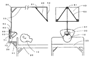
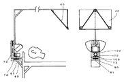
図1は視聴者10がベッド20上に仰臥し、プロジェクタ30から投射される光がスクリーン40上に形成する画像を視聴している図である。
またアーム50はスクリーン上端取り付け部51、スクリーン下端取り付け部52、プロジェクタ取り付け部53、回転板・支柱取り付け部54、支柱55から成り立っており、スクリーン40はスクリーン上端取り付け部51及びスクリーン下端取り付け部52に取り付けられ、プロジェクタはプロジェクタ取り付け部53に取り付けられ、回転板60及び支柱55は回転板・支柱取り付け部54に取り付けられている。
さらに回転板60はアーム保持手段70にも接続され、アーム保持手段70は表示装置の保持手段80を介して、ベッド20に固定されている。
ここで回転板60は2面を持ち、1面が残る1面に対して並行を保ちながら回転軸を中心にして回転が可能な板であることから、1面をアーム保持手段70に固定し、残る1面を回転板・支柱取り付け部54に固定することにより、アーム50はアーム保持手段70に対して、回転中心軸90の周りに回転が可能となる。
さらにアーム保持手段70と回転板・支柱取り付け部54の間に摩擦手段71を置いている。
摩擦手段71は例えば、ゴム成分を主成分とするゴム状組成物のような弾性を持つ材料で、アーム保持手段70に接着され、摩擦手段71と回転板・支柱取り付け部54の間で適度な摩擦力を持たせることができる。Hereinafter, embodiments of the present invention will be described in detail with reference to the drawings.
First Embodiment This embodiment is an embodiment corresponding to the first aspect of the present invention, and FIGS. 1 and 2 are explanatory views of a display device according to the present embodiment.
FIG. 1 is a view in which a
The
Further, the
Here, since the
Further, a friction means 71 is placed between the
The friction means 71 is, for example, an elastic material such as a rubber-like composition containing a rubber component as a main component. A friction force can be given.
このような構成において、スクリーンの質量Ms、スクリーンの重心と回転中心軸との距離をLs、プロジェクタの質量Mp、プロジェクタの重心と回転中心軸との距離をLp、アームの質量Ma、アームの重心と回転中心軸との距離をLaとして、かつアームの重心の位置が回転中心軸に対してスクリーン側にあるとすると、アームとプロジェクタとスクリーンのそれぞれが持つ回転中心軸周りのトルクの合計Ttは
![]()
一方、摩擦手段71によるアームに対しての静止トルクをTsとして
![]()
またTtをほぼゼロとすれば、Tsも小さくでき、アームを非常に軽微な力でアーム保持手段に対して回転させることができる。
従って図2に示すように視聴者が左横臥した場合は、アームに軽く力を加えることで、アームを左側に適度に傾け、スクリーンを視聴者のほぼ正面に持ってくることが可能となる。
なお本実施形態において摩擦手段71は回転板60と別個に設けたが、ディスクブレーキに用いられているような摩擦部材金属などを用いて回転板を構成し、回転板60に摩擦機能を持たせた表示装置も、本実施形態に含まれると考えられる。
さらに、本発明はベッドに付随して使用されるように限定されるものでなく、図8に示したように表示装置の床用保持手段81を用いて、アーム保持手段70を固定すれば、視聴者は床もしくはたたみ21の上の寝具22の上に仰臥もしくは横臥して、本表示装置を利用できることは当然である。In such a configuration, the screen mass Ms, the distance between the center of gravity of the screen and the rotation center axis is Ls, the projector mass Mp, the distance between the center of gravity of the projector and the rotation center axis is Lp, the mass of the arm Ma, and the center of gravity of the arm. And the center of gravity of the arm is on the screen side with respect to the rotation center axis, the total torque Tt around the rotation center axis of each of the arm, the projector, and the screen is
![]()
On the other hand, the static torque on the arm by the friction means 71 is Ts.
![]()
If Tt is made substantially zero, Ts can also be reduced, and the arm can be rotated with respect to the arm holding means with a very slight force.
Therefore, as shown in FIG. 2, when the viewer is lying on the left, it is possible to bring the screen almost in front of the viewer by tilting the arm appropriately to the left by applying a slight force to the arm.
In this embodiment, the friction means 71 is provided separately from the
Further, the present invention is not limited to be used in association with the bed, and if the
また本実施形態のプロジェクタとしては、例えば2006年4月現在株式会社東芝より発売されているTDP−FF1Aを用いることが可能である。
このプロジェクタは質量が電池込みで740グラムであり、プロジェクタからスクリーンまでの距離を80cmとすると、スクリーンはおおよそ22インチとなる。
さらに本実施形態1の設計例では、回転軸からの距離46.7cmに重心がある質量68グラムの22インチのスクリーンと、回転軸からの距離7.4cmにある上記質量740グラムのプロジェクタを、回転軸からの距離18.5cm(スクリーン側)に重心のある質量294グラムのアームに装着した場合、Ttはおよそ20g・cmとなり、Tsは100g・cmあれば十分で、非常に軽い力で回転が可能となる。As the projector of the present embodiment, for example, TDP-FF1A currently available from Toshiba Corporation as of April 2006 can be used.
This projector has a mass of 740 grams including batteries, and if the distance from the projector to the screen is 80 cm, the screen will be approximately 22 inches.
Furthermore, in the design example of the first embodiment, a 22-inch screen with a mass of 68 grams having a center of gravity at a distance of 46.7 cm from the rotation axis, and a projector with a mass of 740 grams at a distance of 7.4 cm from the rotation axis are provided. When mounted on an arm with a mass of 294 grams with a center of gravity at a distance of 18.5 cm (screen side) from the rotation axis, Tt is approximately 20 g · cm, and Ts of 100 g · cm is sufficient. Is possible.
第1の実施形態の効果
本実施形態の表示装置を利用する視聴者は、仰臥した場合はアームを垂直に、左側に横臥した場合はアームを左方向に、また右側に横臥した場合はアームを右方向に軽微な力で回転させることが可能である。
またアームの回転中心軸と、視聴者の頭部軸がほぼ一致させれば、常にスクリーンが視聴者の正面に来るように調整することが可能となる。
なお動作の効果については特許文献1および2に開示されている表示装置と同様であるが、特許文献1および2で必要とされたバランサーが不要であり、かつプロジェクタを用いているため、表示画面サイズが大きいにもかかわらず、特許文献1および2に比べて表示装置の質量を軽減することが可能となり、装置の搬送や設置が容易になったことが特徴である。Effects of First Embodiment A viewer who uses the display device of the present embodiment, when lying on his / her back, makes the arm vertical, when lying on the left side, the arm is directed leftward, and when lying on the right side, the arm is moved. It can be rotated to the right with a slight force.
Further, if the rotation center axis of the arm and the viewer's head axis substantially coincide with each other, it is possible to adjust so that the screen is always in front of the viewer.
The effect of the operation is the same as that of the display device disclosed in
第2の実施形態
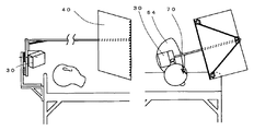
当該実施形態は請求項2に記載の発明に対応した実施形態であり、図3は本実施形態の第1の例における表示装置の説明図である。
ここではアーム50、スクリーン上端取り付け部51、スクリーン下端取り付け部52、プロジェクタ取り付け部53、回転板・支柱取り付け部54、支柱55、回転板60、アーム保持手段70、表示装置の保持手段80は第1の実施形態と同じであり説明を省略する。
また本実施形態の第1の例においては、アーム保持手段70にモータ取り付け板102を介してモータ100が取り付けられ、モータの軸に取り付けられたカラー101は回転板・支柱取り付け部54に接触するように構成されている。
さらに回転板・支柱取り付け部54の1部は回転中心軸から等距離の円周面を形成しており、かつ回転板・支柱取り付け部をプラスチックもしくは金属のような剛性の高い部材とし、カラーを硬質ゴムのような素材とし、回転板・支柱取り付け部とカラーを密着させることで、モータの回転力は回転板・支柱取り付け部に伝達される。Second Embodiment This embodiment is an embodiment corresponding to the invention described in
Here, the
In the first example of this embodiment, the
Furthermore, a part of the rotating plate /
このような構成で、アームとプロジェクタとスクリーンのそれぞれが持つ回転中心軸周りのトルクの合計Ttが、モータおよびカラーによる静止トルクTsmに対して
![]()
ここで、カラーは請求項2で述べている回転力伝達手段である。
なお、回転板・支柱取り付け部及びカラーを剛性の高い部材とし、回転板・支柱取り付け部の円周部にゴム成分を主成分とするゴム状組成物のような弾性を持つシートを接着し、回転板・支柱取り付け部とカラーの間の摩擦力を確保する方式も本実施形態と同様と考えられる
また回転力伝達手段については、カラーの代わりにモータ軸にプーリーを装着し、回転板・支柱取り付け部の円周部とプーリーの間にベルト張るような構成も考えられる。
さらに本実施形態の第1の例ではモータとして直流ギヤードモータを用いており、図示していないが、このモータを時計方向もしくは反時計方向に任意の速度で回転させるための電流を流す駆動回路がモータに接続されており、また前記駆動回路を制御するための操作ボタンがあり、視聴者はこの操作ボタンを操作することにより、アームを好みの方向に回転させ、所望の角度で停止させることができる。With this configuration, the total torque Tt around the rotation center axis of each of the arm, projector, and screen is relative to the static torque Tsm by the motor and the collar.
![]()
Here, the collar is the rotational force transmitting means described in
In addition, the rotating plate / post mounting portion and the collar are made of a highly rigid member, and an elastic sheet such as a rubber-like composition containing a rubber component as a main component is bonded to the circumferential portion of the rotating plate / post mounting portion, The method for securing the frictional force between the rotating plate / post mounting portion and the collar is also considered to be the same as in this embodiment. For the rotational force transmitting means, a pulley is attached to the motor shaft instead of the collar, and the rotating plate / post is supported. A configuration in which a belt is stretched between the circumferential portion of the mounting portion and the pulley is also conceivable.
Furthermore, in the first example of the present embodiment, a DC geared motor is used as the motor, and although not shown, there is a drive circuit for supplying a current for rotating the motor clockwise or counterclockwise at an arbitrary speed. It is connected to a motor and has an operation button for controlling the drive circuit. By operating this operation button, the viewer can rotate the arm in a desired direction and stop it at a desired angle. it can.
さらに本実施例の第2の例を図4に示した。
本例では、第1の例に加えてアーム保持手段70と回転板・支柱取り付け部54の間に摩擦手段71を置いている。
この例の静止トルクはモータおよびカラーによる静止トルクTsmに加え、摩擦手段71による静止トルクをTsが加算され、
![]()
本例では、摩擦手段71がアーム保持手段70と回転板・支柱取り付け部54の間であって、かつ回転中心軸90から離れた位置にあるため、アーム保持手段と回転板・支柱取り付け部の間の平行度を保つことが容易で、アームが回転したときの、回転以外の好ましくない動作、いわゆるガタが少ない効果がある。Furthermore, the 2nd example of the present Example was shown in FIG.
In this example, in addition to the first example, the friction means 71 is placed between the arm holding means 70 and the rotating plate /
The static torque in this example is added to the static torque Tsm by the motor and the collar, and the static torque by the friction means 71 is added to Ts.
![]()
In this example, the friction means 71 is located between the arm holding means 70 and the rotary plate /
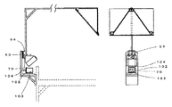
加えて本実施例の第3の例を図5に示した。
本例ではアーム保持手段70にモータ取り付け板102を介してサーボモータ103が取り付けられ、モータの軸に取り付けられたロッド104は回転板・支柱取り付け部54を回転させるように構成されている。
本例においては、サーボモータの静止トルクTssがTtよりも大きければアームは静止し、サーボモータの動作トルクがTtよりも大きければアームを回転させることができる。
ここで、ロッドは請求項2で述べている回転力伝達手段である。
本例の応用例としては、特許文献1にも述べられているような視聴者の頭部に角度センサーを装着し、このセンサー出力を利用して、サーボモータを制御することにより、視聴者の頭部の傾きに応じてアームの角度を変えることも可能である。In addition, a third example of this embodiment is shown in FIG.
In this example, the
In this example, the arm can be stationary if the static torque Tss of the servo motor is larger than Tt, and the arm can be rotated if the operating torque of the servo motor is larger than Tt.
Here, the rod is the rotational force transmitting means described in
As an application example of this example, an angle sensor is mounted on the viewer's head as described in
第2の実施形態の効果
本実施形態の表示装置を利用する視聴者は、第1及び第2の実施形態に比べ、視聴者はアームに触れることなく、モータ駆動回路の制御ボタンを押すだけあるいは、傾きセンサーを装着するだけでアームを回転させ、スクリーンを容易に適視位置に置くことが可能となる。Effects of Second Embodiment A viewer who uses the display device of the present embodiment can simply press the control button of the motor drive circuit without touching the arm, as compared with the first and second embodiments. By simply attaching the tilt sensor, the arm can be rotated and the screen can be easily placed at the appropriate viewing position.
第3の実施形態
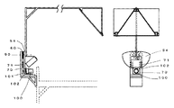
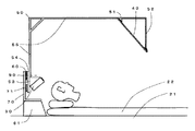
当該実施形態は請求項3に記載の発明に対応した実施形態であり、図6及び図7は本実施形態における表示装置の説明図である。
本実施形態では、第1もしくは第2の実施形態に加え、図6に示したようにアーム保持手段70と表示装置の保持手段80の間に第2の回転中心軸91を有する回転板72を有している。
第1もしくは第2の実施形態においては、常にアーム及びスクリーン40がベッドの上もしくは脇にあるため、ベッド上での起床・着床動作や治療施設などでの治療を妨げる問題があり、用途によっては使いづらい場合もある。
これに対し本実施例では、図7で示したように視聴者が表示装置を使用しない場合は、アーム保持手段70を通常視聴時に対して、第2の回転中心軸91を中心に水平方向に90度回転させることが可能で、また表示装置の保持手段80はベッドのヘッド部分の外部に接続されているため、上記のアーム保持手段70の回転動作により、このアーム及びスクリーン40をベッドのヘッド部分の外部に置くことが可能となる利点がある。Third Embodiment This embodiment is an embodiment corresponding to the invention described in
In this embodiment, in addition to the first or second embodiment, a rotating plate 72 having a second
In the first or second embodiment, since the arm and the
On the other hand, in this embodiment, as shown in FIG. 7, when the viewer does not use the display device, the arm holding means 70 is set in the horizontal direction around the second
第3の実施形態の効果
本実施形態の表示装置を利用する視聴者は、第1、第2及び第3の実施形態に比べ、視聴者は表示装置を使用しないとき、アーム保持手段70の回転動作により、このアームをベッドのヘッド部分の外部に置くことが可能となり、ベッド上での起床・着床動作や治療施設などでの治療を妨げることがない利点がある。Effects of Third Embodiment A viewer using the display device of the present embodiment rotates the arm holding means 70 when the viewer does not use the display device, as compared with the first, second, and third embodiments. The operation makes it possible to place this arm outside the head portion of the bed, and there is an advantage that it does not interfere with the wake-up / landing operation on the bed or the treatment in the treatment facility.
10・・・視聴者
20・・・ベッド
21・・・床もしくはたたみ
22・・・寝具
30・・・プロジェクタ
40・・・スクリーン
50・・・アーム
51・・・スクリーン上端取り付け部
52・・・スクリーン下端取り付け部
53・・・プロジェクタ取り付け部
54・・・回転板・支柱取り付け部
55・・・支柱
60・・・回転板
70・・・アーム保持手段
71・・・摩擦手段
72・・・回転板
80・・・表示装置の保持手段
81・・・表示装置の床用保持手段
90・・・回転中心軸
91・・・第2の回転中心軸
100・・・モータ
101・・・カラー
102・・・モータ取り付け板
103・・・サーボモータ
104・・・ロッドDESCRIPTION OF
Claims (3)
Priority Applications (1)
| Application Number | Priority Date | Filing Date | Title |
|---|---|---|---|
| JP2006155328A JP2007304530A (en) | 2006-05-08 | 2006-05-08 | Display apparatus |
Applications Claiming Priority (1)
| Application Number | Priority Date | Filing Date | Title |
|---|---|---|---|
| JP2006155328A JP2007304530A (en) | 2006-05-08 | 2006-05-08 | Display apparatus |
Publications (1)
| Publication Number | Publication Date |
|---|---|
| JP2007304530A true JP2007304530A (en) | 2007-11-22 |
Family
ID=38838479
Family Applications (1)
| Application Number | Title | Priority Date | Filing Date |
|---|---|---|---|
| JP2006155328A Pending JP2007304530A (en) | 2006-05-08 | 2006-05-08 | Display apparatus |
Country Status (1)
| Country | Link |
|---|---|
| JP (1) | JP2007304530A (en) |
Cited By (3)
| Publication number | Priority date | Publication date | Assignee | Title |
|---|---|---|---|---|
| JP2011028209A (en) * | 2009-07-24 | 2011-02-10 | Guangzhou Grandview Crystal Screen Co Ltd | Screen device |
| AT12689U1 (en) * | 2011-07-14 | 2012-10-15 | Vamed Kmb Krankenhausman Und Betr Sfuehrungs Gesmbh | MEDIA TROLLEY |
| JP2020124528A (en) * | 2020-04-01 | 2020-08-20 | パラマウントベッド株式会社 | Bed device |
-
2006
- 2006-05-08 JP JP2006155328A patent/JP2007304530A/en active Pending
Cited By (4)
| Publication number | Priority date | Publication date | Assignee | Title |
|---|---|---|---|---|
| JP2011028209A (en) * | 2009-07-24 | 2011-02-10 | Guangzhou Grandview Crystal Screen Co Ltd | Screen device |
| AT12689U1 (en) * | 2011-07-14 | 2012-10-15 | Vamed Kmb Krankenhausman Und Betr Sfuehrungs Gesmbh | MEDIA TROLLEY |
| JP2020124528A (en) * | 2020-04-01 | 2020-08-20 | パラマウントベッド株式会社 | Bed device |
| JP7118104B2 (en) | 2020-04-01 | 2022-08-15 | パラマウントベッド株式会社 | sleeping device |
Similar Documents
| Publication | Publication Date | Title |
|---|---|---|
| WO2021063230A1 (en) | Camera module, electronic apparatus, and camera module control method | |
| JP2004242128A (en) | Camera pan-head for aerial photography | |
| JP2007096493A (en) | Imaging apparatus | |
| JP2005201954A (en) | Projector having device for automatically adjusting right-and-left projecting direction | |
| JP2007304530A (en) | Display apparatus | |
| JP2006344685A5 (en) | ||
| JP2004109392A (en) | Thin display apparatus provided with rotational mechanism | |
| JP4665254B2 (en) | Display device | |
| JP2009204639A (en) | Image forming apparatus | |
| JP2008233235A (en) | Adapter device | |
| JP4811011B2 (en) | Image forming apparatus | |
| JP6241240B2 (en) | Image shake prevention device and camera system | |
| JP6102787B2 (en) | Camera device and surveillance camera device | |
| CN112782926A (en) | Projection screen horizontal and vertical adjusting structure without pixel loss and projector | |
| JP2007264568A (en) | Monitor device | |
| JP2010122247A (en) | Projection type video display unit | |
| JP2008136100A (en) | Pan and tilt cradle | |
| JP2009009071A (en) | Projector having support-leg | |
| JP2020067573A (en) | Image display device and rotation device | |
| JP2005195711A (en) | Display device retaining appliance | |
| KR20140064055A (en) | Camera module | |
| JPH02282717A (en) | Image blur correcting device for camera | |
| JP2007289592A (en) | Automatic horizontal control device utilizing force of center of gravity | |
| JP2009088838A (en) | Camera instrument | |
| JP2008219539A (en) | Display device turntable and display device provided with it |