JP2007298604A - Optical sheet support, back light for liquid crystal display using the same, liquid crystal display and rear-projection type display - Google Patents
Optical sheet support, back light for liquid crystal display using the same, liquid crystal display and rear-projection type display Download PDFInfo
- Publication number
- JP2007298604A JP2007298604A JP2006124899A JP2006124899A JP2007298604A JP 2007298604 A JP2007298604 A JP 2007298604A JP 2006124899 A JP2006124899 A JP 2006124899A JP 2006124899 A JP2006124899 A JP 2006124899A JP 2007298604 A JP2007298604 A JP 2007298604A
- Authority
- JP
- Japan
- Prior art keywords
- fabric
- optical sheet
- liquid crystal
- crystal display
- light
- Prior art date
- Legal status (The legal status is an assumption and is not a legal conclusion. Google has not performed a legal analysis and makes no representation as to the accuracy of the status listed.)
- Pending
Links
Images

Landscapes
- Liquid Crystal (AREA)
- Securing Globes, Refractors, Reflectors Or The Like (AREA)
- Planar Illumination Modules (AREA)
- Optical Elements Other Than Lenses (AREA)
Abstract
Description
本発明は、ディスプレイに用いられる光学シート支持体ならびにそれを用いた液晶ディスプレイ用バックライトなどに関し、詳しくは、特に直下型液晶ディスプレイ用バックライトに好適な光学シート支持体およびそれを用いた液晶ディスプレイ用バックライトなどに関する。 TECHNICAL FIELD The present invention relates to an optical sheet support used for a display and a backlight for a liquid crystal display using the same, and more particularly, an optical sheet support suitable for a backlight for a direct liquid crystal display and a liquid crystal display using the same. It is related with the backlight etc.
近年、携帯機器をはじめ、テレビ、モニター及びノートパソコンなど、あらゆる用途において様々な原理を応用したディスプレイが用いられている。中でも液晶ディスプレイ(以下、LCDという。)は、携帯機器用の小画面製品から、モニターやテレビなどの大画面製品に至るまで幅広く用いられている。LCDでは、偏光板に挟まれた液晶素子に画面裏側から均一に光を照射するために、面光源であるバックライトを画面裏側に設けることにより画像表示を行っている。 In recent years, displays using various principles have been used in various applications such as portable devices, televisions, monitors, and notebook computers. Among them, liquid crystal displays (hereinafter referred to as LCDs) are widely used from small screen products for portable devices to large screen products such as monitors and televisions. In the LCD, an image is displayed by providing a backlight, which is a surface light source, on the back side of the screen in order to irradiate the liquid crystal element sandwiched between the polarizing plates uniformly from the back side of the screen.
このようなLCDに用いられるバックライトは大きく2種類に分類され、(1)画面の真下に直接単数または複数の蛍光管を並べる直下型と、(2)透明なアクリル板等を加工した導光板を用い、その側面に配置された蛍光管から光線を導光板に入射し、導光板に刻まれた散乱ドットの作用を用いて面状に光線を広げつつ、観察方向に光を取り出すサイドライト型とがある。これら型式のものは、それぞれの特徴を活かし、直下型は大型化への対応が容易なタイプであり、サイドライト型は小型および薄型化への対応が容易なタイプである。 Backlights used in such LCDs are roughly classified into two types: (1) a direct type in which one or more fluorescent tubes are arranged directly under the screen, and (2) a light guide plate in which a transparent acrylic plate is processed. Sidelight type that takes out light in the observation direction while spreading the light into a plane using the action of the scattering dots carved in the light guide plate from the fluorescent tube placed on its side There is. These types make use of their respective characteristics, the direct type is a type that can easily cope with an increase in size, and the sidelight type is a type that can easily cope with a reduction in size and thickness.
これらのバックライトには、単に画面裏側から光を入射するだけでなく、画面全体を均一に、しかも明るく光らせることが求められる。このような要求を満たすため、バックライトには、光拡散シート、プリズムシート、又は輝度向上シート(偏光分離シート)などの光学機能性シート(以下、光学シートという。)が組み込まれている。 These backlights are required not only to receive light from the back side of the screen but also to make the entire screen shine uniformly and brightly. In order to satisfy such requirements, an optical functional sheet (hereinafter, referred to as an optical sheet) such as a light diffusion sheet, a prism sheet, or a brightness enhancement sheet (polarized light separation sheet) is incorporated in the backlight.
これら光学シートのうち、光拡散シートは以下のように機能する。たとえば直下型バックライトの場合、蛍光管は画面真下に配置される。そのため、蛍光管の形状に対応した輝度ムラが顕著に現れる。そこで、光散乱性を有する厚さ2〜3mmの光拡散板(光拡散シート)を蛍光管上側に配置して、蛍光管像を遮蔽し、光拡散板から出射する光線の出射分布を均等化させる。この直下型バックライト用の光拡散板には、例えば、メタクリル樹脂などの透明樹脂とシリコーン樹脂粒子などの拡散成分を、射出成形法や押出成形法を用いて練り混んでシート成形した光拡散板(光拡散シート)等が用いられる(特許文献1参照)。そして、この光拡散板は、さらにその上に積層されるプリズムシートや輝度向上シート(偏光分離シート)等の光学シートを支持する機能も併せ持っている。 Among these optical sheets, the light diffusion sheet functions as follows. For example, in the case of a direct type backlight, the fluorescent tube is arranged directly under the screen. Therefore, luminance unevenness corresponding to the shape of the fluorescent tube appears remarkably. Therefore, a light diffusing plate (light diffusing sheet) with a thickness of 2 to 3 mm having light scattering properties is arranged on the upper side of the fluorescent tube to shield the fluorescent tube image and equalize the emission distribution of the light emitted from the light diffusing plate. Let The light diffusing plate for this direct type backlight is, for example, a light diffusing plate obtained by kneading and mixing a transparent resin such as methacrylic resin and a silicone resin particle using an injection molding method or an extrusion molding method. (Light diffusion sheet) or the like is used (see Patent Document 1). The light diffusing plate also has a function of supporting an optical sheet such as a prism sheet or a brightness enhancement sheet (polarization separation sheet) laminated thereon.
しかしながら、厚さ2〜3mmもある光拡散板を用いては、次のような問題があった。(1)液晶ディスプレイは薄型であるのが大きな魅力であるが、厚さが厚くなってしまう、(2)直下型に好適な大型化液晶ディスプレイに用いると非常に重くなり、かつ、コストが高くなる、という欠点である。 However, the use of a light diffusing plate having a thickness of 2 to 3 mm has the following problems. (1) Although it is a big attraction that the liquid crystal display is thin, the thickness becomes thick. (2) When it is used for a large-sized liquid crystal display suitable for a direct type, it becomes very heavy and high in cost. This is a drawback.
また、特許文献2には、織物からなる光拡散シートを透明基体からなる樹脂板で支持固定する構造が開示されている。しかしながら、この文献に記載の技術も、樹脂板を用いるために上記問題点は解決されない上に、織物を樹脂板にしわもたるみもなく埋設、挟持、粘着する作業が必要で、そして織物と樹脂板との屈折率との関係を最適に選定しなければならないというわずらわしさがあった。さらに、樹脂板の厚み分だけ底上げされた状態で光学シートが支持されることになるので、樹脂板の厚み分だけ光学シートは光源から遠くなってしまう欠点がある。光源から遠くなると、光の強さは弱くなり光学シートを透過する光も弱くなるので液晶ディスプレイバックライトの画面が暗くなってしまうという問題もあった。
また、特許文献3には、織編物の隙間にバインダー樹脂を充填した光拡散シートが開示されている。しかしながら、この文献に記載の光拡散シートも、フィルムなどの支持体に貼り合わせられ、さらにそれを別の拡散板で支持して用いられるものであって、その基本的構造はなんら変わるものではないから、特許文献2に記載の技術と同様の問題を有するものであった。
本発明は、かかる従来技術の問題点を解消し、従来技術のように樹脂板を使うことなくディスプレイに用いられる光学シートを支持することが可能な支持体であって、かつ、薄く、軽く、コンパクト性に優れ、しかも輝度ムラが少なく、コストダウンを図ることも可能な光学シート支持体を提供することを目的とする。 The present invention eliminates the problems of the prior art, and is a support capable of supporting an optical sheet used in a display without using a resin plate as in the prior art, and is thin, light, An object of the present invention is to provide an optical sheet support that is excellent in compactness, has little luminance unevenness, and can achieve cost reduction.
すなわち本発明は、ディスプレイに装備される光学シートの支持体であって、糸により構成された布帛からなり、該糸が、異形断面形状の繊維を含んでいることを特徴とする光学シート支持体である。 That is, the present invention is an optical sheet support provided in a display, which is made of a fabric composed of yarns, and the yarns include fibers having irregular cross-sectional shapes. It is.
また本発明は、本発明の光学シート支持体を備えていることを特徴とする、液晶ディスプレイ用バックライトである。 The present invention also provides a backlight for a liquid crystal display, comprising the optical sheet support of the present invention.
また本発明は、本発明の液晶ディスプレイバックライトを搭載していることを特徴とする液晶ディスプレイである。 The present invention also provides a liquid crystal display equipped with the liquid crystal display backlight of the present invention.
また本発明は、本発明の光学シート支持体を備えていることを特徴とする背面投射型ディスプレイである。 Moreover, this invention is a rear projection type display provided with the optical sheet support body of this invention.
本発明の光学シート支持体によれば、ディスプレイに装備される光学シートを樹脂板を使うことなく光源により近い位置で支持できる。また、本発明の光学シート支持体は、薄くて、軽く、かつ、光の透過性や輝度ムラ低減効果に優れており、コストダウン化を図ることも可能となる。その結果、液晶ディスプレイバックライト、液晶ディスプレイ、背面投射型ディスプレイなどとしても、輝度を損なうことなく、軽量化かつコンパクトに、さらに耐衝撃性に優れ、低価格なものとすることができる。 According to the optical sheet support of the present invention, the optical sheet mounted on the display can be supported at a position closer to the light source without using a resin plate. In addition, the optical sheet support of the present invention is thin and light, and is excellent in the light transmittance and the luminance unevenness reduction effect, and the cost can be reduced. As a result, a liquid crystal display backlight, a liquid crystal display, a rear projection display, and the like can be reduced in weight and compact without impairing luminance, and can be further reduced in impact resistance and price.
以下、本発明を実施するための最良の形態を説明する。 Hereinafter, the best mode for carrying out the present invention will be described.
本発明に係る光学シート支持体の基本構造は、ディスプレイに装備される光学シートの支持体であり、糸により構成される布帛からなる。すなわち、本発明の光学シート支持体(以下、単に支持体という。)は、ディスプレイに装備される光学シートを樹脂板ではなく、以下に述べる特定構造の布帛で支持する。その結果、特にディスプレイに装備される光学シートを光源(導光板や反射シートなども含む)により近い位置で支持できる。そして、布帛であるので、前述したように薄く、軽く、コンパクト性に優れ、さらに、組み立て時や運搬時に割れることもないので耐衝撃性に優れ、また、コストダウン化を図ることも可能となる。 The basic structure of the optical sheet support according to the present invention is a support for an optical sheet mounted on a display, and is made of a fabric composed of yarn. That is, the optical sheet support of the present invention (hereinafter simply referred to as a support) supports the optical sheet mounted on the display not with a resin plate but with a fabric having a specific structure described below. As a result, in particular, the optical sheet provided in the display can be supported at a position closer to the light source (including the light guide plate and the reflection sheet). And since it is a fabric, as mentioned above, it is thin, light, and excellent in compactness. Further, since it is not cracked during assembly or transportation, it is excellent in impact resistance, and it is possible to reduce costs. .
本発明の支持体の布帛は、糸が、異形断面形状の繊維を含んでいることを特徴とする。このため、繊維間が隙間なく充填されたように配列できるので、輝度ムラが少ないという作用効果を有する。 The fabric of the support according to the present invention is characterized in that the yarn contains fibers having an irregular cross-sectional shape. For this reason, since it can arrange so that it may be filled with no gap between fibers, it has the effect that there is little brightness nonuniformity.
本発明において、繊維の材質としては、ポリメチルメタクリレートやポリアクリロニトリル等のアクリル繊維、ポリエチレンテレフタレートやポリトリメチレンテレフタレート、ポリブチレンテレフタレート等のポリエステル繊維、ナイロン6やナイロン66等のポリアミド繊維、ポリウレタン繊維、ポリエチレンやポリプロピレン等のポリオレフィン繊維、ポリイミド繊維、ポリアセタール繊維、ポリエーテル繊維、ポリスチレン繊維、ポリカーボネート繊維、ポリエステルアミド繊維、ポリフェニレンサルファイド繊維、ポリ塩化ビニル繊維、ポリエーテルエステル繊維、ポリ酢酸ビニル繊維、ポリビニルブチラール繊維、ポリフッ化ビニリデン繊維、エチレン−酢酸ビニル共重合繊維、フッ素樹脂系繊維、及びスチレン−アクリル共重合繊維、アラミド繊維などの合成繊維が好ましい。これら繊維は、1種類の合成繊維からなっていてもよいし、2種類以上の合成繊維から構成されていてもよい。
In the present invention, as the material of the fiber, acrylic fiber such as polymethyl methacrylate and polyacrylonitrile, polyester fiber such as polyethylene terephthalate, polytrimethylene terephthalate, polybutylene terephthalate, polyamide fiber such as
なかでも、吸湿安定性や熱安定性等の点から、ポリエステル繊維やポリフェニレンサルファイド繊維、フッ素樹脂系繊維等を用いるのが好ましく、特に汎用性からポリエステル繊維を用いるのが好ましい。 Of these, polyester fibers, polyphenylene sulfide fibers, fluororesin fibers, and the like are preferably used from the viewpoint of moisture absorption stability and thermal stability, and polyester fibers are particularly preferable from the viewpoint of versatility.
単繊維の繊度としては、0.5dtex以上10dtex以下のものが好ましく用いられるが、特に限定されるものではない。単繊維繊度が0.5dtex未満であると、フィラメント数が少ない場合、強度不足となる懸念があるが、フィラメント数を多くすると高コストとなり、10dtexを超えると、強度面では問題ないが、平均輝度が低くなる傾向であるため好ましくない。 The fineness of the single fiber is preferably 0.5 dtex or more and 10 dtex or less, but is not particularly limited. If the single fiber fineness is less than 0.5 dtex, there is a concern that the strength may be insufficient if the number of filaments is small, but if the number of filaments is increased, the cost becomes high, and if it exceeds 10 dtex, there is no problem in terms of strength, but the average luminance Is not preferable because it tends to be low.
上述したように本発明の支持体の布帛を構成する単繊維の断面形状は異形断面であり、本発明において「異形断面」とは、略三角形、略四角形、略星形、略Y形、略田形など、円形状以外の形状をいい、その他の円形以外の断面形状のものも含む。 As described above, the cross-sectional shape of the single fiber constituting the fabric of the support of the present invention is an irregular cross-section, and in the present invention, the “abnormal cross-section” means a substantially triangular shape, a substantially square shape, a substantially star shape, a substantially Y shape, A shape other than a circular shape, such as a rice field, is included, and other cross-sectional shapes other than a circle are included.
異形断面の形成の仕方としては、紡糸口金の断面形状を上記形状に形成した口金から上記材質の原液を紡出させる公知の方法の他、略丸形断面からなる繊維で布帛を形成した後、例えば加熱プレス処理により、布帛を構成する繊維の断面形状を異形断面に変形させたものでも良い。 As a method of forming the irregular cross-section, in addition to a known method of spinning the stock solution of the above material from a spinneret in which the cross-sectional shape of the spinneret is formed in the above-mentioned shape, after forming a fabric with fibers having a substantially round cross-section, For example, the cross-sectional shape of the fibers constituting the fabric may be deformed into a deformed cross-section by a heat press process.
糸条を構成する繊維のフィラメント数としては、単繊維1本のモノフィラメントであってもよいし、2本以上のマルチフィラメントであってもよい。好ましくは、繊維間を隙間なく充填させて、輝度ムラを少なくし、液晶ディスプレイ画面を均一に表示することが可能なマルチフィラメントの方が好ましい。このような点から言えば、マルチフィラメントの単繊維数としては、20〜300本が好ましく用いられる。 The number of filaments constituting the yarn may be a single filament monofilament or two or more multifilaments. Preferably, a multifilament that fills the fibers without gaps, reduces unevenness in brightness, and can display the liquid crystal display screen uniformly is preferable. Speaking from this point, 20 to 300 multifilament single fibers are preferably used.
本発明者は、マルチフィラメントであると、その配列の仕方によって輝度ムラが大きく影響を受けることを見出した。すなわち、布帛は光源からの光を本発明の支持体上部に位置する光学シート(図2の符号1参照)に十分導入する必要があるが、繊維の断面形状が丸断面の場合、隣り合う繊維の外形形状が曲面であるため、単繊維と単繊維との間に空間が発生しやすくなる。すると、単糸間の空間部分と、それ以外の繊維同士が重なり合った交差部分との間で輝度の差が発生してしまうため、輝度ムラが大きくなってしまう。
The present inventor has found that luminance unevenness is greatly affected by the arrangement of multifilaments. That is, the fabric needs to sufficiently introduce the light from the light source into the optical sheet (see
一方、繊維の断面形状が異形断面の場合は、異形断面の辺と辺とが平行に沿うように配列されるので、繊維間が隙間なく充填されたように配列された状態でマルチフィラメントが構成できる。その結果、布帛を光が透過するときには、必ず繊維の中を透過するようになるので、単繊維間の空間部分と、それ以外の繊維同士が重なり合った交差部分などといった布帛の場所による光の透過量に差が生じにくくなり、輝度ムラを抑えることができる。 On the other hand, when the cross-sectional shape of the fiber is an irregular cross-section, since the sides of the irregular cross-section are arranged in parallel, the multifilament is configured in a state where the fibers are arranged without gaps. it can. As a result, when light passes through the fabric, it always passes through the fiber. Therefore, the light is transmitted by the location of the fabric, such as the space between the single fibers and the intersection where the other fibers overlap. Differences in the amount are less likely to occur, and luminance unevenness can be suppressed.
本発明の支持体における布帛の輝度ムラとしては、50〜350cd/m2の範囲内であることが好ましい。輝度ムラが少なければ少ないほど液晶ディスプレイ画面での映りは均一となるが、輝度ムラが大きくなると、明るい部分と暗い部分との差が激しくなるため、液晶ディスプレイ画面での映りが不均一となってしまうのである。一方、50cd/m2にまで抑えられれば、現行のディスプレイ用途に対しては十分である。 The brightness unevenness of the fabric in the support of the present invention is preferably in the range of 50 to 350 cd / m 2 . The smaller the brightness unevenness, the more uniform the image on the LCD screen. However, when the brightness unevenness increases, the difference between the bright and dark areas becomes severe, and the image on the LCD screen becomes uneven. It ends up. On the other hand, if it is suppressed to 50 cd / m 2 , it is sufficient for the current display application.
布帛を構成する糸条に異形断面の繊維が含まれる割合としては、糸条における繊維の総本数に対して50%以上が好ましく、80%以上がより好ましく、最も好ましくは布帛を構成する全ての繊維の断面形状が異形断面で構成されていることである。異形断面の繊維の割合が50質量%よりも少なくなると、略丸形断面の繊維の影響が現れ、輝度ムラが大きくなるため好ましくない。上記割合に異形断面糸を混在させる方法としては例えば、紡糸口金の断面形状を、略三角形、略四角形、略星形、略Y形、略田形などの形状に形成した口金で紡糸した単糸から布帛を構成したり、略丸形断面からなる繊維で布帛を形成した後、例えば加熱プレス処理により、布帛を構成する繊維の断面形状を異形断面に変形させたりする方法が挙げられる。 The ratio of the fibers having irregular cross-sections contained in the yarn constituting the fabric is preferably 50% or more, more preferably 80% or more, and most preferably all of the fibers constituting the fabric. That is, the cross-sectional shape of the fiber is an irregular cross-section. If the proportion of the fiber having the irregular cross section is less than 50% by mass, the influence of the fiber having a substantially round cross section appears, and the luminance unevenness increases, which is not preferable. As a method of mixing the irregular cross-section yarns in the above ratio, for example, the spinneret cross-sectional shape is made from a single yarn spun with a die formed into a shape such as a substantially triangular shape, a substantially quadrangular shape, a substantially star shape, a substantially Y shape, or a substantially tabular shape. Examples include a method of forming a fabric or forming a fabric with fibers having a substantially round cross section, and then deforming the cross-sectional shape of the fibers forming the fabric into a deformed cross section by, for example, a heat press process.
次に、繊維の集合体である糸条の総繊度としては、10dtex以上300dtex以下であるのがよい。総繊度が10dtex未満であると、布帛が薄くなりすぎて、光源が見えやすくなり、輝度ムラが大きくなり易い。一方、繊度が300dtexよりも大きくなると、布帛が厚くなりすぎて、光の透過量が少なくなり、輝度が小さくなり易い。このような観点において、より好ましくは50dtex以上100dtex以下である。 Next, the total fineness of the yarn that is an aggregate of fibers is preferably 10 dtex or more and 300 dtex or less. When the total fineness is less than 10 dtex, the fabric is too thin, the light source is easily visible, and the luminance unevenness is likely to increase. On the other hand, when the fineness is larger than 300 dtex, the fabric becomes too thick, and the amount of light transmission is reduced, so that the luminance is likely to be reduced. In such a viewpoint, it is more preferably 50 dtex or more and 100 dtex or less.
さらに、本発明者らは鋭意検討した結果、該布帛の平均輝度ならびに輝度ムラは、布帛の通気量と相関があることを見出した。すなわち、上述の通り布帛を構成する糸条と糸条との間および糸条を構成する単糸と単糸との間に空間が多くなるほど、特に空間が多い糸条と糸条との間において光の透過量が増加する一方で、空気自身も流れやすくなるということに着目し、通気量と輝度の関係を調べた結果、布帛の通気量が高くなるほど、布帛の明るい部分と暗い部分が発生しやすくなり、布帛の通気量と光の透過量には相関性があることを見出したのである。 Furthermore, as a result of intensive studies, the present inventors have found that the average brightness and brightness unevenness of the fabric are correlated with the air flow rate of the fabric. That is, as described above, the space between the yarns constituting the fabric and the yarns and between the single yarns constituting the yarns and the single yarns increases, especially between the yarns and yarns having more space. Focusing on the fact that while the amount of transmitted light increases, air itself also tends to flow, and as a result of investigating the relationship between the amount of ventilation and the brightness, the brighter and darker portions of the fabric appear as the amount of ventilation of the fabric increases. It has been found that there is a correlation between the amount of ventilation of the fabric and the amount of transmitted light.
輝度ムラを少なくするための布帛の好ましい通気量としては、0.1〜5.0cm3/cm2・secの範囲内、より好ましくは0.1〜3.0cm3/cm2・secの範囲内である。通気量が0.1cm3/cm2・sec未満になると輝度ムラは少なくなるが光の透過量も少なくなるため、十分な輝度が得られず液晶ディスプレイ画面が暗くなってしまうため好ましくない。また、通気量が5.0cm3/cm2・secを超えると平均輝度は高くなるが輝度ムラが大きくなるため、液晶ディスプレイ画面が不均一となるため好ましくない。 Preferred air permeability of the fabric to reduce the luminance unevenness, in the range of 0.1~5.0cm 3 / cm 2 · sec, more preferably from 0.1~3.0cm 3 / cm 2 · sec Is within. If the air flow rate is less than 0.1 cm 3 / cm 2 · sec, the luminance unevenness is reduced, but the light transmission amount is also reduced, so that sufficient luminance cannot be obtained and the liquid crystal display screen becomes dark, which is not preferable. On the other hand, if the air flow rate exceeds 5.0 cm 3 / cm 2 · sec, the average luminance is increased, but the luminance unevenness is increased.
布帛の形態としては、織物、編物などいかなる構成のものであってもよいが、取り扱い時の寸法安定性がよい織物が好ましい。寸法安定性が悪いと、展張等して固定する際に布帛自体が変形して伸縮した部分が発生する。そのため、伸びた部分は繊維の量が少なくなり、縮んだ部分の繊維の量は多くなる。伸縮した部分は伸縮して変形していない部分と比べ、光の透過量が多い部分と少ない部分といった差が生じるため、輝度ムラが発生することになる。さらに、支持体の上に光学シートを積層したときには光学シートの重みで支持体自体が伸びてしまい、たるみが生じる。たるんだ部分は光源に近くなるので、明るくなるなどしてバックライト画面上に輝度ムラが発生してしまう。よって、繊維に一定方向の負荷をかけて製布する織物などのように、寸法安定性に優れるものを使用することが好ましい。 The fabric may have any configuration such as a woven fabric or a knitted fabric, but a woven fabric having good dimensional stability during handling is preferable. If the dimensional stability is poor, the fabric itself is deformed and stretched when it is fixed by stretching or the like. Therefore, the amount of fiber in the stretched portion decreases, and the amount of fiber in the contracted portion increases. Since the stretched portion has a difference between a portion with a large amount of light transmission and a portion with a small amount of light transmission compared to a portion that is not stretched and deformed, luminance unevenness occurs. Furthermore, when the optical sheet is laminated on the support, the support itself is stretched by the weight of the optical sheet, and sagging occurs. Since the sagging part is close to the light source, the brightness becomes bright and uneven brightness occurs on the backlight screen. Therefore, it is preferable to use a material having excellent dimensional stability, such as a woven fabric that is woven by applying a load in a certain direction.
織物の織り組織としては、平織り、綾織り、朱子織り等を採用することができ、輝度ムラを抑える点から平織り等の目合いが均一な組織が好ましい。 As the woven structure of the woven fabric, a plain weave, a twill weave, a satin weave, or the like can be adopted, and a structure having a uniform texture such as a plain weave is preferable from the viewpoint of suppressing luminance unevenness.
支持体が織物から構成される場合、その織物のカバーファクターとしては、1000以上2500以下が好ましい。 When the support is composed of a woven fabric, the cover factor of the woven fabric is preferably 1000 or more and 2500 or less.
カバーファクターとは、次式で算出される因子であり、織物を構成する繊維の織り密度を示している。
カバーファクター=タテ糸密度(本/2.54cm)×[タテ糸繊度(dtex)]1/2+ヨコ糸密度(本/2.54cm)×[ヨコ糸繊度(dtex)]1/2
カバーファクターが1000よりも小さいと、布帛を構成する繊維の量が少なすぎるので、布帛での光の拡散が小さくなってしまい、輝度ムラが大きくなりすぎる。一方、カバーファクターが2500よりも大きいと、布帛を構成する繊維の量が多すぎて光が十分に透過できず、十分な輝度が得られないため液晶ディスプレイ画面が暗くなり易い。カバーファクターは、さらには1300以上2200以下の範囲が好ましく、特に1500以上2000以下の範囲が好ましい。
The cover factor is a factor calculated by the following equation, and indicates the weave density of the fibers constituting the fabric.
Cover factor = Vertical yarn density (main / 2.54 cm) × [Vertical yarn fineness (dtex)] 1/2 + Weft density (main / 2.54 cm) × [Weft yarn fineness (dtex)] 1/2
When the cover factor is less than 1000, the amount of fibers constituting the fabric is too small, so that the diffusion of light in the fabric becomes small and the luminance unevenness becomes too large. On the other hand, if the cover factor is larger than 2500, the amount of fibers constituting the fabric is too large to transmit light sufficiently, and sufficient brightness cannot be obtained, so that the liquid crystal display screen tends to be dark. The cover factor is more preferably in the range of 1300 to 2200, and particularly preferably in the range of 1500 to 2000.
本発明において、支持体は、展張して固定する際の張力による寸法変形を小さくするために、布帛の状態で加熱処理を行い寸法変化を抑制するヒートセット等を施した布帛であることが好ましい。具体的には、4.9N/5cmの荷重を負荷し、24時間経過後の伸び率(以下、クリープという。)が、布帛の縦方向、横方向ともに10%以下となるものが好ましい。支持体は、布帛の自重と光学シートの重みが加わった状態で長期間使用されるので、クリープが大きいと徐々に伸びてしまい、その結果たるみが生じて上記の通り、輝度ムラが発生する。したがって、クリープは10%以下が好ましい。より好ましくは5%以下であり、さらに好ましくは3%以下である。 In the present invention, the support is preferably a fabric subjected to heat treatment or the like in which the heat treatment is performed in the state of the fabric to suppress the dimensional change in order to reduce the dimensional deformation due to the tension when being stretched and fixed. . Specifically, it is preferable that a load of 4.9 N / 5 cm is applied and the elongation after 24 hours (hereinafter referred to as creep) is 10% or less in both the longitudinal and lateral directions of the fabric. Since the support is used for a long time in a state where the weight of the fabric and the weight of the optical sheet are added, if the creep is large, the support gradually grows, resulting in sagging and uneven brightness as described above. Therefore, the creep is preferably 10% or less. More preferably, it is 5% or less, and more preferably 3% or less.
また、支持体は、ディスプレイの光源が点灯している間は光源中に含まれる紫外線に暴露され、黄変、強度劣化をする場合がある。支持体が黄変すると、黄変した支持体を透過した光の色調が変化してしまいディスプレイで表示される画面の色調も変化してしまう。よって、支持体は、布帛に耐紫外線処理を施したものであることが好ましい。耐紫外線処理とは、紫外線吸収剤等の光安定剤を用いて処理することである。光安定剤とは、(1)紫外線の遮蔽、吸収、(2)ハイドロペルオキシドの非ラジカル分解、(3)励起化合物の消光、(4)微量重金属の捕捉、(5)ラジカル捕捉、のいずれか1つ以上の機能を有するものである。 Further, the support may be exposed to ultraviolet rays contained in the light source while the light source of the display is lit, and may turn yellow or deteriorate strength. When the support turns yellow, the color tone of the light transmitted through the yellowed support changes, and the color tone of the screen displayed on the display also changes. Therefore, it is preferable that the support is a fabric subjected to UV resistance treatment. Ultraviolet resistant treatment is treatment using a light stabilizer such as an ultraviolet absorber. The light stabilizer is any one of (1) shielding and absorption of ultraviolet rays, (2) non-radical decomposition of hydroperoxide, (3) quenching of excited compounds, (4) trapping of trace heavy metals, and (5) trapping of radicals. It has one or more functions.
具体的な光安定剤としては、例えば、トリアジン系化合物、ベンゾフェノン系化合物、ジベンゾフェノン系化合物、サリチレート系化合物、シアノアクリレート系化合物、オキサニリド系化合物、ホルムアミジン系化合物等の主に紫外線遮蔽、吸収効果を有する紫外線吸収剤、また、フェノール系化合物、リン系化合物、有機銅錯体系化合物、ヒドラジン系化合物等、主にラジカル捕捉の効果がある酸化防止剤、ラジカル捕捉能やハイドロパーオキサイド分解能、金属イオン捕捉能を有するヒンダード・アミン光安定剤等である。光安定剤は特にこれらに限定されるものではなく、布帛を構成する繊維の種類や光安定化処理をする加工方法によって選定することができる。また、光安定剤は1種類を用いてもよいし、2種類以上を併用してもよい。 Specific examples of the light stabilizer include, for example, triazine compounds, benzophenone compounds, dibenzophenone compounds, salicylate compounds, cyanoacrylate compounds, oxanilide compounds, formamidine compounds, etc. UV-absorbing agents, phenolic compounds, phosphorus compounds, organic copper complex compounds, hydrazine compounds, etc., mainly antioxidants with radical scavenging effect, radical scavenging ability and hydroperoxide resolution, metal ions A hindered amine light stabilizer having a capturing ability. The light stabilizer is not particularly limited to these, and can be selected according to the type of fiber constituting the fabric and the processing method for performing the light stabilization treatment. Moreover, one type of light stabilizer may be used, or two or more types may be used in combination.
光安定剤を付与する方法としては、スプレー法、コーティング法、プリンティング法等、繊維の表面に付与する方法であってもよいし、布帛や繊維の内部に拡散させる方法であってもよい。布帛もしくは繊維内部に拡散する方法としては、光安定剤を含む水溶液に布帛または繊維を浸漬して加熱する浴中吸尽法、または、光安定剤を含む水溶液に布帛または繊維を浸漬してマングルなどで所定の付着量に絞った後、乾熱処理をするパッド・キュア法などを採用できる。なお、光安定剤の付与は、繊維に付与してから布帛を構成する方法、布帛にしてから付与する方法のどちらでも採用することができるが、後者の方が処理の安定性が高く、またコストを抑えることができるので好ましい。 As a method of applying the light stabilizer, a method of applying to the surface of the fiber such as a spray method, a coating method, or a printing method may be used, or a method of diffusing inside the fabric or fiber may be used. As a method of diffusing inside the fabric or fiber, the cloth or fiber is immersed in an aqueous solution containing a light stabilizer and heated in a bath, or the fabric or fiber is immersed in an aqueous solution containing a light stabilizer and mangle. For example, a pad-cure method in which a dry heat treatment is performed after narrowing to a predetermined adhesion amount can be adopted. The light stabilizer can be applied by either the method of forming the fabric after applying it to the fiber or the method of applying the light stabilizer after forming the fabric, but the latter has higher processing stability, This is preferable because the cost can be reduced.
光安定剤を布帛もしくは繊維の内部に拡散させる場合(浴中吸尽法)、付与する光安定剤の量は布帛の重量に対し0.1〜5.0重量%、さらに好ましくは0.5〜3.0重量%がよい。0.1重量%よりも少ないと目的とする耐紫外線耐久性が発揮出来ない場合があり、5重量%を越えると繊維の強力が低下したり、コストアップになる場合がある。 When the light stabilizer is diffused into the fabric or fiber (exhaust in bath), the amount of light stabilizer applied is 0.1 to 5.0% by weight, more preferably 0.5%, based on the weight of the fabric. ~ 3.0 wt% is preferred. If the amount is less than 0.1% by weight, the intended durability against ultraviolet rays may not be exhibited. If the amount exceeds 5% by weight, the strength of the fiber may be reduced or the cost may be increased.
スプレー法やパッド・キュア法等、表面に光安定剤を付与する方法の場合、紫外線吸収剤等の付着量は、布帛の重量に対し、0.1〜10.0重量%、さらに好ましくは0.5〜8.0重量%、さらに好ましくは0.5〜5.0重量%である。0.1重量%よりも少ないと、浴中吸尽法の場合と同様に目的とする耐紫外線耐久性が発揮出来ない場合があり、10.0重量%を越えると、付着した光安定剤によって光の透過が妨げられて輝度が小さくなったり、コストアップになる場合がある。 In the case of a method of applying a light stabilizer to the surface, such as a spray method or a pad-cure method, the adhesion amount of an ultraviolet absorber or the like is 0.1 to 10.0% by weight, more preferably 0, based on the weight of the fabric. 0.5 to 8.0% by weight, more preferably 0.5 to 5.0% by weight. If the amount is less than 0.1% by weight, the target UV resistance may not be achieved as in the case of the exhaustion method in a bath. If the amount exceeds 10.0% by weight, the attached light stabilizer may There are cases where the transmission of light is hindered and the luminance is reduced or the cost is increased.
以上に述べた本発明の支持体によれば、支持体自体の厚みを薄くできるので、光学シートを光源により近い位置で支持できるとともに、光源から発する光をより強い状態で透過でき、ディスプレイの画面を明るくすることが可能になる。また、厚みが薄いのでコンパクト性に優れ、軽く、かつ、耐衝撃性にも優れて運搬やディスプレイ組み立て工程で割れたりヒビが入ったりといった問題が発生することを防ぐことができる。その結果、大幅なコストダウンを図ることも可能である。 According to the support of the present invention described above, since the thickness of the support itself can be reduced, the optical sheet can be supported at a position closer to the light source, and the light emitted from the light source can be transmitted in a stronger state, and the display screen Can be brightened. Moreover, since the thickness is thin, it is excellent in compactness, light and excellent in impact resistance, and it is possible to prevent problems such as cracking and cracking during transportation and display assembly process. As a result, it is possible to significantly reduce costs.
上述の様な利点により、本発明の光学シート支持体は、液晶ディスプレイのバックライトに好適に装備される。すなわち本発明の液晶ディスプレイ用バックライトは、本発明の光学シート支持体を備えていることを特徴とするものである。 Due to the advantages as described above, the optical sheet support of the present invention is suitably equipped with a backlight of a liquid crystal display. That is, the backlight for a liquid crystal display of the present invention is characterized by including the optical sheet support of the present invention.
本発明の液晶ディスプレイ用バックライトにおいて、本発明の光学シート支持体がプリズムシートおよび偏光分離シートの少なくとも一方を支持していることが好ましい。 In the backlight for a liquid crystal display of the present invention, it is preferable that the optical sheet support of the present invention supports at least one of a prism sheet and a polarization separation sheet.
本発明の支持体を液晶ディスプレイ用のバックライトに適用した好ましい構成を図1および図2に例示するが、本発明はこれらの構成に限られるものではない。 Although the preferable structure which applied the support body of this invention to the backlight for liquid crystal displays is illustrated in FIG. 1 and FIG. 2, this invention is not limited to these structures.
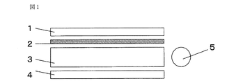
図1は、本発明の支持体を液晶ディスプレイのサイドライト型バックライトに組み込んだ場合のバックライトの構成を模式的に示す図である。図1において、サイドライト型バックライトは、透明なアクリル板を加工した導光板3と、その側面に配置された1本または複数の線状の蛍光管(光源)5と、導光板3の底面側に配置された反射シート4と、導光板3の表面側に配置された本発明の支持体2と、その支持体2のさらに上部に配置されたプリズムシートや偏光分離シート等の輝度向上シート(光学シート)1で構成されている。
FIG. 1 is a diagram schematically showing the configuration of a backlight when the support of the present invention is incorporated in a sidelight-type backlight of a liquid crystal display. In FIG. 1, the sidelight-type backlight includes a
図2は、本発明の支持体2を液晶ディスプレイの直下型バックライトに組み込んだ場合のバックライトの構成を模式的に示す図である。図2において、直下型バックライトは、反射シート4が敷き詰められた筐体6内部に複数の線状の蛍光管(光源)5が配置されており、蛍光管(光源)5の上方に本発明の支持体2が配置され、さらにその支持体2の上部にプリズムシートや偏光分離シート等の輝度向上シート(光学シート)1が配置されている。そして、本実施形態においては、支持体2が大きくたわむことを防ぐために支持柱7も設置している。
FIG. 2 is a diagram schematically showing a configuration of a backlight when the
これら図1や図2で示したバックライトの光学シート1の上方に液晶セル(図示せず)を配置することによって、液晶ディスプレイが構成される。
By disposing a liquid crystal cell (not shown) above the
また、上述した本発明の支持体2は、背面投射型ディスプレイにも好ましく用いることができる。
Moreover, the
背面投射型ディスプレイは、CRTや液晶パネル等で生成された画像を投影レンズにより背面投射型スクリーンに拡大投影して映像を映し出すディスプレイである。ここで用いられるスクリーンは、投射光を適切に配光して良好な画像認識を可能にする働きを担うものである。スクリーンとして、例えば、拡散粒子を練り混んだ等方的な拡散性を示す拡散板を用いることも可能であるが、投射光は発散的に入射するためにスクリーンの周辺部は外向きの指向性をもち、スクリーン正面方向から観察した場合には中心で明るく周辺が暗く、また斜めから観察した場合には近い方で明るく遠い方で暗くなる等、画面上での輝度ムラが顕著になる。このような輝度ムラを排除するためには、投射レンズ側にフレネルレンズシートを配置するのが一般的であるが、このフレネルレンズシートなどの光学シートを支持するために、本発明の支持体を用いることができる。 The rear projection display is a display that displays an image by enlarging and projecting an image generated by a CRT, a liquid crystal panel, or the like onto a rear projection screen using a projection lens. The screen used here bears the function of appropriately distributing projection light and enabling good image recognition. As the screen, for example, it is possible to use a diffuser plate with isotropic diffusivity mixed with diffusing particles. However, since the incident light is divergently incident, the periphery of the screen is directed outward. When observed from the front side of the screen, the brightness unevenness on the screen becomes noticeable, such as bright and dark at the center and dark when viewed from an oblique direction and darker near and brighter. In order to eliminate such luminance unevenness, it is common to arrange a Fresnel lens sheet on the projection lens side, but in order to support an optical sheet such as this Fresnel lens sheet, the support of the present invention is used. Can be used.
フレネルレンズシートは、投射レンズからスクリーンに発散的に入射する投射光をほぼスクリーンに垂直な平行光に変換する働きをする。そのため、スクリーン各部での光の方向をスクリーン面に垂直な方向に変換し、この後に拡散すれば、どのような方向から観察しても画面全体に渡ってほぼ均一な明るさを実現することができる。そして、本発明の支持体でこのフレネルレンズシートに積層すれば、フレネルレンズシートを支持するだけでなく、それを通して平行光となった光を拡散することができる。 The Fresnel lens sheet functions to convert the projection light divergingly incident on the screen from the projection lens into parallel light substantially perpendicular to the screen. Therefore, if the direction of light in each part of the screen is changed to a direction perpendicular to the screen surface and then diffused, almost uniform brightness can be realized over the entire screen regardless of the direction of observation. it can. And if it laminates | stacks on this Fresnel lens sheet with the support body of this invention, it can diffuse not only the Fresnel lens sheet but the light which became parallel light through it.
なお、従来、フレネルレンズシートを支持し、該シートからの光を拡散する役割は、一般的にレンチキュラーレンズシートが担っていた。レンチキュラーレンズシートは、映像光が入射する平行光を水平方向に拡散し視野角を拡大する異方拡散性を有するシートである。しかしながら、レンチキュラーレンズシートも通常2〜3mm程度の厚みがあり、上記したような課題を有するものであった。したがって、背面投射型ディスプレイにおいて、該レンチキュラーレンズシートの変わりに本発明の支持体を用いれば、上記したような液晶ディスプレイと同様の効果を得ることができる。 Conventionally, the lenticular lens sheet generally plays a role of supporting the Fresnel lens sheet and diffusing light from the sheet. The lenticular lens sheet is a sheet having anisotropic diffusivity that diffuses parallel light incident with image light in the horizontal direction and expands the viewing angle. However, the lenticular lens sheet usually has a thickness of about 2 to 3 mm and has the above-described problems. Therefore, in the rear projection type display, if the support of the present invention is used instead of the lenticular lens sheet, the same effect as the above-described liquid crystal display can be obtained.
以下、本発明について実施例を挙げて説明するが、本発明は必ずしもこれに限定されるものではない。 Hereinafter, although an example is given and the present invention is explained, the present invention is not necessarily limited to this.
[測定・評価方法]
(1)単糸断面形状
視差走査型顕微鏡にて、単糸の断面形状を観察した。
[Measurement and evaluation method]
(1) Single yarn cross-sectional shape The single yarn cross-sectional shape was observed with a parallax scanning microscope.
(2)布帛の厚み
JIS L 1096:1999 8.5に準じて、試料の異なる5か所についてシックネスダイヤルゲージを用いて、押し圧力3.5N/cm2の加圧下、厚さを落ち着かせるために10秒間待った後に厚さを測定し、平均値を算出した。
(2) Thickness of the fabric In accordance with JIS L 1096: 1999 8.5, the thickness is settled under pressure of 3.5 N / cm 2 using a thickness dial gauge at five different points of the sample. After waiting for 10 seconds, the thickness was measured and the average value was calculated.
(3)布帛の目付け
JIS L 1096:1999 8.4.2に則り、20cm×20cmの試験片を3枚採取し、それぞれの質量(g)を量り、その平均値を1m2当たりの質量(g/m2)で表した。
(3) Fabric weight of fabric In accordance with JIS L 1096: 1999 8.4.2, three test pieces of 20 cm × 20 cm were sampled, each mass (g) was weighed, and the average value was the mass per 1 m 2 ( g / m 2 ).
(4)布帛の通気量
JIS L 1096:1999 8.27.1 A法(フラジール形法)に準じて測定した。試料の異なる5か所から約20cm×20cmの試験片を採取し、フラジール形試験機を用い、円筒の一端(吸気側)に試験片を取り付けた。試験片を取り付けた後、加減抵抗器によって傾斜形気圧計が125Paの圧力を示すように吸込みファンを調整し、そのときの垂直形気圧計の示す圧力と、使用した空気孔の種類とから、試験機に付属の表によって試験片を通過する空気量を求め、5枚の試験片についての平均値を算出した。
(4) Aeration rate of fabric Measured according to JIS L 1096: 1999 8.27.1 Method A (Fragile Form Method). Test pieces of about 20 cm × 20 cm were collected from five different locations of the samples, and the test pieces were attached to one end (intake side) of the cylinder using a Frazier type tester. After attaching the test piece, the suction fan was adjusted so that the inclination type barometer showed a pressure of 125 Pa by an adjusting resistor, and from the pressure indicated by the vertical type barometer and the type of air hole used, The amount of air passing through the test piece was obtained from a table attached to the test machine, and the average value for the five test pieces was calculated.
(5)クリープ
布帛(タテ・ヨコ方向おのおのn=3ずつ)を長さ30cm、幅5cmの試験片に裁断し、つかみ間隔20cmで試験片をつかみ、幅方向にほぼ均一に4.9N/5cmの張力が加わるように荷重を加え、布帛を長さ方向が垂直になるようにつり下げて室温(約25℃)に維持した状態で静かに24時間放置した。24時間後につかみ間隔(L(cm))を測定し、伸び率(%)を下記の式で算出し、タテ、ヨコそれぞれn=3の平均値を算出した。
伸び率(%)=((L(cm)―20(cm))/20(cm))÷100 。
(5) Creep Fabrics (each n = 3 in the vertical and horizontal directions) are cut into test pieces with a length of 30 cm and a width of 5 cm, and the test pieces are held at a holding interval of 20 cm, and the width is almost uniformly 4.9 N / 5 cm. A load was applied so as to apply the tension, and the fabric was suspended so that the lengthwise direction was vertical and kept at room temperature (about 25 ° C.) for 24 hours. After 24 hours, the grip interval (L (cm)) was measured, the elongation percentage (%) was calculated by the following formula, and the average value of n = 3 for each of vertical and horizontal was calculated.
Elongation rate (%) = ((L (cm) −20 (cm)) / 20 (cm)) ÷ 100.
(6)平均輝度・輝度ムラ
図2に示す直下型バックライトにおいて、その蛍光管5の上に設置されている拡散板(厚さ2mmのアクリル板)を取り外し、本実施例の便宜上、透明のプラスチックス板(厚さ2mmのポリカーボネート板)を置き、その上に本発明の布帛を設置し、蛍光管5を60分間点灯して光源を安定させた後に、測定サンプル側からEYSCALE−3((株)アイ・システム社製)を用い、付属のCCDカメラを直下型バックライトの中心から90cmの地点に、直下型バックライトの面に対して正面となるように設置し、輝度(cd/m2)を測定した。測定箇所は、蛍光管5の真上の輝度(Lmax)と、蛍光管と蛍光管との間の輝度(Lmin)を測定した。
平均輝度、輝度ムラは以下の式から算出され、平均輝度は値が高いほど優れ、輝度ムラは値が小さいほど優れる。
平均輝度(cd/m2)=((Lmaxの平均値)+(Lminの平均値))÷2
輝度ムラ(cd/m2)=(Lmaxの平均値)−(Lminの平均値) 。
(6) Average luminance / luminance unevenness In the direct type backlight shown in FIG. 2, the diffusion plate (acrylic plate having a thickness of 2 mm) installed on the
The average luminance and the luminance unevenness are calculated from the following equations. The average luminance is higher as the value is higher, and the luminance unevenness is higher as the value is lower.
Average luminance (cd / m 2 ) = ((average value of L max ) + (average value of L min )) / 2
Unevenness of luminance (cd / m 2 ) = (average value of L max ) − (average value of L min ).
(7)耐紫外線効果
UV照射試験装置(装置名:アイ・スーパーUVテスター SUV−P1、使用ランプ:M04−L21SUV 4kW 岩崎電気(株)社製)にて処理時間60hr、処理温度63℃、照射強度100mW/cm2で処理を行い、処理前後の色変化を目視にて確認し、ほとんど変色なしを○、明らかに変色が認められる布帛を×と判定した。
(7) Ultraviolet ray resistance effect UV irradiation test apparatus (device name: Eye Super UV Tester SUV-P1, used lamp: M04-
[実施例1]
(原糸)
ポリエチレンテレフタレート樹脂を、丸形孔を有する紡糸口金で紡出し、延伸し、単繊維が丸型断面で繊度3.1dtexの56dtex−18フィラメントのポリエチレンテレフタレートフィラメントヤーンと、単繊維が丸型断面で繊度2.3dtexの84dtex−36フィラメントのポリエチレンテレフタレートフィラメントヤーンとを得た。
[Example 1]
(Raw yarn)
Polyethylene terephthalate resin is spun and drawn with a spinneret having a round hole, and a single fiber is a 56 dtex-18 filament polyethylene terephthalate filament yarn with a fineness of 3.1 dtex and a fineness of a single fiber with a round cross section. A 2.3 dtex 84 dtex-36 filament polyethylene terephthalate filament yarn was obtained.
(製織)
得られた56dtex−18フィラメントのポリエチレンテレフタレートフィラメントヤーンをタテ糸に用い、また、84dtex−36フィラメントのポリエチレンテレフタレートフィラメントヤーンをヨコ糸に用い、織機にて製布し、タテ織り密度118本/2.54cm、ヨコ織り密度92本/2.54cmの平織りの布帛を得た。
(Weaving)
The obtained 56 dtex-18 filament polyethylene terephthalate filament yarn was used as warp yarn, and the 84 dtex-36 filament polyethylene terephthalate filament yarn was used as a weft yarn, and was woven with a loom to obtain a warp weave density of 118/2. A plain-woven fabric having a length of 54 cm and a horizontal weave density of 92 / 2.54 cm was obtained.
(加熱プレス処理)
得られた布帛を、加熱温度180℃、圧力390kPa、速度3m/minの処理条件にて加熱ローラーによる加熱プレス処理を行い、単繊維の断面形状を異形断面に加工した。単繊維の断面形状は略三角形であった。
(Hot press processing)
The obtained fabric was subjected to a heat press treatment with a heating roller under the treatment conditions of a heating temperature of 180 ° C., a pressure of 390 kPa, and a speed of 3 m / min to process the cross-sectional shape of the single fiber into an irregular cross-section. The cross-sectional shape of the single fiber was substantially triangular.
(耐紫外線処理)
トリアジン系紫外線吸収剤(商品名:CIBAFAST P NEW チバ・スペシャルティ・ケミカルズ(株)社製)を布帛重量(上記構成の布帛 30×40cm)対比20%で、均染剤(商品名:ベネラップ101 一方社油脂工業(株)社製)0.5g/Lと、pH調整剤(酢酸と酢酸ソーダーとを体積比1:2の割合で混合した溶液)0.5g/Lと、芳香族カルボン酸、およびN−アルキルフタルイミド系拡散促進剤(商品名:Univadine PB new チバ・スペシャルティ・ケミカルズ(株)社製)2.0g/Lを、浴比1:20で耐紫外線処理液を調整し、昇温速度3℃/分にて約30分かけて135℃まで昇温し、135℃にて60分間保持し、冷却速度3℃/分にて約30分かけて約40℃まで冷却し、浴中吸尽処理を行った。その後、60℃の温水にて10分間の湯洗を行い、続けて常温水にて5分間すすぎ処理を行い、処理後の布帛を約1昼夜常温で乾燥させ、紫外線吸収剤の付着量2.56%の布帛を得た。
(UV resistant)
Triazine-based UV absorber (trade name: CIBAFAST P NEW, manufactured by Ciba Specialty Chemicals Co., Ltd.) is 20% of fabric weight (fabric 30 × 40 cm having the above structure) and leveling agent (trade name: Benerup 101) (Manufactured by Yushi Kogyo Co., Ltd.) 0.5 g / L, pH adjuster (a solution in which acetic acid and sodium acetate are mixed at a volume ratio of 1: 2) 0.5 g / L, aromatic carboxylic acid, And an N-alkylphthalimide diffusion accelerator (trade name: Universadin PB new, manufactured by Ciba Specialty Chemicals Co., Ltd.) 2.0 g / L, adjusting the UV-resistant treatment solution at a bath ratio of 1:20, and raising the temperature The temperature was raised to 135 ° C. over about 30 minutes at a rate of 3 ° C./minute, held at 135 ° C. for 60 minutes, cooled to about 40 ° C. over about 30 minutes at a cooling rate of 3 ° C./minute, Exhaust treatment went. Thereafter, it is washed with warm water at 60 ° C. for 10 minutes, followed by rinsing with room temperature water for 5 minutes, and the treated fabric is dried at room temperature for about one day and night, and the amount of UV absorber attached. 56% of the fabric was obtained.
(バックライト)
図2に示す32インチの直下型バックライトを構成した。上記で得られた布帛を支持体2とし、たるみ、しわ等なく展張して筐体6の四辺部分に両面テープにて固定した。光学シート1として、プリズムシートと偏光分離シートとを載せたところ、良好に支持できた。さらに、蛍光灯5を点灯したところ、バックライトとして十分な輝度が得られた。
(Backlight)
The 32-inch direct type backlight shown in FIG. 2 was constructed. The fabric obtained above was used as the
その他の特性の評価結果については表1に示す。 The evaluation results of other characteristics are shown in Table 1.
[実施例2]
(原糸)
ポリエチレンテレフタレート樹脂を、Y字形の孔を有する紡糸口金で紡出し、延伸し、単繊維が略三角型断面で繊度3.5dtexの84dtex−24フィラメントのポリエチレンテレフタレートフィラメントヤーンを得た。
[Example 2]
(Raw yarn)
Polyethylene terephthalate resin was spun with a spinneret having a Y-shaped hole and stretched to obtain a polyethylene terephthalate filament yarn of 84 dtex-24 filaments having a single-filament having a substantially triangular cross section and a fineness of 3.5 dtex.
(製織)
得られた84dtex−24フィラメントのポリエチレンテレフタレートフィラメントヤーンをタテ糸、ヨコ糸のそれぞれに用い、織機にて製布し、タテ織り密度96本/2.54cm、ヨコ織り密度84本/2.54cmの平織りの布帛を得た。
(Weaving)
The obtained 84 dtex-24 filament polyethylene terephthalate filament yarn was used for warp and weft yarns, and weaved using a loom. The warp weave density was 96 / 2.54 cm, and the weave density was 84 / 2.54 cm. A plain weave fabric was obtained.
(加熱プレス処理・耐紫外線処理])
得られた布帛に対し、実施例1と同様にして加熱プレス処理及び耐紫外線処理を施した。
(Hot press treatment / UV resistant treatment)
The obtained fabric was subjected to a heat press treatment and an ultraviolet resistant treatment in the same manner as in Example 1.
(バックライト)
図2に示す32インチの直下型バックライトを構成した。上記で得られた布帛を支持体2とし、たるみ、しわ等なく展張して筐体6の四辺部分に両面テープにて固定した。光学シート1として、プリズムシートと偏光分離シートとをのせたところ、良好に支持できた。さらに、蛍光灯5を点灯したところ、バックライトとして十分な輝度が得られた。
(Backlight)
The 32-inch direct type backlight shown in FIG. 2 was constructed. The fabric obtained above was used as the
その他の特性の評価結果については表1に示す。 The evaluation results of other characteristics are shown in Table 1.
[比較例1]
(原糸・製織)
実施例1で用いたのと同様のポリエチレンテレフタレートフィラメントヤーンをタテ糸、ヨコ糸のそれぞれに用い、実施例1と同様にして製織した。
[Comparative Example 1]
(Raw yarn / weaving)
A polyethylene terephthalate filament yarn similar to that used in Example 1 was used for each of the warp yarn and the weft yarn, and woven in the same manner as in Example 1.
(加熱プレス処理)
加熱プレス処理は、施さなかった。
(Hot press processing)
No heat press treatment was performed.
(耐紫外線処理)
耐紫外線処理を、実施例1と同様にして施した。
(UV resistant)
Ultraviolet resistant treatment was performed in the same manner as in Example 1.
(バックライト)
図2に示す32インチの直下型バックライトを構成した。上記で得られた布帛を支持体2とし、たるみ、しわ等なく展張して筐体6の四辺部分に両面テープにて固定した。光学シート1として、プリズムシートと偏光分離シートをのせたところ、良好に支持できた。さらに、蛍光灯5を点灯したところ、実施例1,2で得られたバックライトと同様に十分な輝度は得られていたが、実施例1、2に比べ輝度ムラが大きく、明るい部分と暗い部分が散見された。
(Backlight)
The 32-inch direct type backlight shown in FIG. 2 was constructed. The fabric obtained above was used as the
その他の特性の評価結果については表1に示す。 The evaluation results of other characteristics are shown in Table 1.
[比較例2]
(原糸)
実施例1と同様にして、単繊維が丸型断面で繊度3.1dtexの56dtex−18フィラメントのポリエチレンテレフタレートフィラメントヤーンと、単繊維が丸型断面で繊度2.3dtexの84dtex−36フィラメントのポリエチレンテレフタレートフィラメントヤーンとを得た。
[Comparative Example 2]
(Raw yarn)
In the same manner as in Example 1, a 56 dtex-18 filament polyethylene terephthalate filament yarn with a single fiber having a round cross section and a fineness of 3.1 dtex, and a 84 dtex-36 filament polyethylene terephthalate with a single fiber having a round cross section and a fineness of 2.3 dtex. Obtained with filament yarn.
(製織)
得られた56dtex−18フィラメントのポリエチレンテレフタレートフィラメントヤーンをタテ糸に用い、また、84dtex−36フィラメントのポリエチレンテレフタレートフィラメントヤーンをヨコ糸に用い、織機にて製布し、タテ織り密度110本/2.54cm、ヨコ織り密度81本/2.54cmの平織りの布帛を得た。
(Weaving)
The obtained 56 dtex-18 filament polyethylene terephthalate filament yarn was used for warp yarns, and 84 dtex-36 filament polyethylene terephthalate filament yarn was used for weft yarns. A plain weave fabric of 54 cm and a weft density of 81 / 2.54 cm was obtained.
(バックライト)
図2に示す32インチの直下型バックライトを構成した。上記で得られた布帛を支持体2とし、たるみ、しわ等なく展張して筐体6の四辺部分に両面テープにて固定した。光学シート1として、プリズムシートと偏光分離シートをのせたところ、良好に支持できた。さらに、蛍光灯5を点灯したところ、実施例1,2で得られたバックライトと同様に十分な輝度は得られていたが、実施例1、2に比べ輝度ムラが大きく、明るい部分と暗い部分が散見された。
(Backlight)
The 32-inch direct type backlight shown in FIG. 2 was constructed. The fabric obtained above was used as the
その他の特性の評価結果については表1に示す。 The evaluation results of other characteristics are shown in Table 1.

表1の評価結果から明らかなように、実施例1、2の布帛は比較例1、2よりも輝度ムラを低減できることが分かった。 As is clear from the evaluation results in Table 1, it was found that the fabrics of Examples 1 and 2 can reduce luminance unevenness more than Comparative Examples 1 and 2.
本発明は、液晶ディスプレイに好適に用いられる。 The present invention is suitably used for a liquid crystal display.
1 輝度向上シート(光学シート)
2 光学シート支持体(本発明)
3 導光板
4 反射シート
5 蛍光管
6 筐体
7 支持柱
1 Brightness improvement sheet (optical sheet)
2 Optical sheet support (present invention)
3
Claims (12)
Priority Applications (1)
| Application Number | Priority Date | Filing Date | Title |
|---|---|---|---|
| JP2006124899A JP2007298604A (en) | 2006-04-28 | 2006-04-28 | Optical sheet support, back light for liquid crystal display using the same, liquid crystal display and rear-projection type display |
Applications Claiming Priority (1)
| Application Number | Priority Date | Filing Date | Title |
|---|---|---|---|
| JP2006124899A JP2007298604A (en) | 2006-04-28 | 2006-04-28 | Optical sheet support, back light for liquid crystal display using the same, liquid crystal display and rear-projection type display |
Publications (1)
| Publication Number | Publication Date |
|---|---|
| JP2007298604A true JP2007298604A (en) | 2007-11-15 |
Family
ID=38768163
Family Applications (1)
| Application Number | Title | Priority Date | Filing Date |
|---|---|---|---|
| JP2006124899A Pending JP2007298604A (en) | 2006-04-28 | 2006-04-28 | Optical sheet support, back light for liquid crystal display using the same, liquid crystal display and rear-projection type display |
Country Status (1)
| Country | Link |
|---|---|
| JP (1) | JP2007298604A (en) |
Cited By (3)
| Publication number | Priority date | Publication date | Assignee | Title |
|---|---|---|---|---|
| JP2009282133A (en) * | 2008-05-20 | 2009-12-03 | Sharp Corp | Optical sheet and display |
| WO2020004082A1 (en) * | 2018-06-28 | 2020-01-02 | キヤノン株式会社 | Anti-reflection coating material, optical member having anti-reflection film provided thereto, optical equipment, and imaging device |
| CN111051050A (en) * | 2017-09-01 | 2020-04-21 | 贝内克-凯利科股份公司 | Light-permeable multilayer composite film |
-
2006
- 2006-04-28 JP JP2006124899A patent/JP2007298604A/en active Pending
Cited By (4)
| Publication number | Priority date | Publication date | Assignee | Title |
|---|---|---|---|---|
| JP2009282133A (en) * | 2008-05-20 | 2009-12-03 | Sharp Corp | Optical sheet and display |
| CN111051050A (en) * | 2017-09-01 | 2020-04-21 | 贝内克-凯利科股份公司 | Light-permeable multilayer composite film |
| US11338543B2 (en) * | 2017-09-01 | 2022-05-24 | Benecke-Kaliko Ag | Light-permeable multi-layer composite film |
| WO2020004082A1 (en) * | 2018-06-28 | 2020-01-02 | キヤノン株式会社 | Anti-reflection coating material, optical member having anti-reflection film provided thereto, optical equipment, and imaging device |
Similar Documents
| Publication | Publication Date | Title |
|---|---|---|
| US9494817B2 (en) | Display with nonwoven diffuser | |
| TW200815794A (en) | Lens sheet, planar light source device and liquid crystal display device | |
| JP5109346B2 (en) | Light diffusing film and direct surface light source using the same | |
| JP2007298604A (en) | Optical sheet support, back light for liquid crystal display using the same, liquid crystal display and rear-projection type display | |
| JP2007140495A (en) | Optical sheet-supporting body, backlight for liquid crystal display using same, liquid crystal display, and rear projection type display | |
| JPWO2005116518A1 (en) | Liquid crystal display device and backlight device | |
| CN100492135C (en) | Backlight module for improving liquid crystal display device light leakage | |
| WO2007046274A1 (en) | Optical sheet-supporting body, backlight for liquid crystal display using same, and liquid crystal display | |
| JP2007316403A (en) | Lens-like diffusion sheet for liquid crystal television | |
| KR100977272B1 (en) | Light panel with light diffusion particles | |
| WO2007029606A1 (en) | Light diffusion film and surface light source using same | |
| KR20170012070A (en) | Fiberous-web structure type diffusion sheet, Manufacturing method thereof and Back light unit containing the same | |
| WO2010137590A1 (en) | Light diffusion sheet | |
| JP2008112025A (en) | Optical sheet support, backlight for liquid crystal display using the same, liquid crystal display and rear-projection type display | |
| JP2004198725A (en) | Liquid crystal display, direct back light, and diffusing plate | |
| JP2007140499A (en) | Light diffusion member and surface light source using the same | |
| JPH09304602A (en) | Light diffusion sheet | |
| TWI253528B (en) | Luminous device | |
| TW200846770A (en) | Liquid crystal display and backlight module thereof | |
| JP2007140477A (en) | Light diffusion film and surface light source using the same | |
| CN200993709Y (en) | Backlight module | |
| KR100621808B1 (en) | Radiograph viewer for providing a sufrace light source a structure of blu(back light unit) | |
| CN220040794U (en) | Multifunctional miniature composite board with hexagonal prism structure on surface | |
| KR20110027277A (en) | The backligth unit for lcd display | |
| JPH10115712A (en) | Polarizing woven fabric |