JP2007298241A - Electric heater system - Google Patents

Electric heater system Download PDF

Info

Publication number
JP2007298241A
JP2007298241A JP2006127906A JP2006127906A JP2007298241A JP 2007298241 A JP2007298241 A JP 2007298241A JP 2006127906 A JP2006127906 A JP 2006127906A JP 2006127906 A JP2006127906 A JP 2006127906A JP 2007298241 A JP2007298241 A JP 2007298241A
Authority
JP
Japan
Prior art keywords
heat
electric heater
terminal
heat generating
contact
Prior art date
Legal status (The legal status is an assumption and is not a legal conclusion. Google has not performed a legal analysis and makes no representation as to the accuracy of the status listed.)
Pending
Application number
JP2006127906A
Other languages
Japanese (ja)
Inventor
Naotarou Abe
尚太郎 阿部
Current Assignee (The listed assignees may be inaccurate. Google has not performed a legal analysis and makes no representation or warranty as to the accuracy of the list.)
Marelli Corp
Original Assignee
Calsonic Kansei Corp
Priority date (The priority date is an assumption and is not a legal conclusion. Google has not performed a legal analysis and makes no representation as to the accuracy of the date listed.)
Filing date
Publication date
Application filed by Calsonic Kansei Corp filed Critical Calsonic Kansei Corp
Priority to JP2006127906A priority Critical patent/JP2007298241A/en
Priority to PCT/JP2007/059171 priority patent/WO2007129608A1/en
Publication of JP2007298241A publication Critical patent/JP2007298241A/en
Pending legal-status Critical Current

Links

Images

Classifications

    • FMECHANICAL ENGINEERING; LIGHTING; HEATING; WEAPONS; BLASTING
    • F24HEATING; RANGES; VENTILATING
    • F24HFLUID HEATERS, e.g. WATER OR AIR HEATERS, HAVING HEAT-GENERATING MEANS, e.g. HEAT PUMPS, IN GENERAL
    • F24H3/00Air heaters
    • F24H3/02Air heaters with forced circulation
    • F24H3/04Air heaters with forced circulation the air being in direct contact with the heating medium, e.g. electric heating element
    • F24H3/0405Air heaters with forced circulation the air being in direct contact with the heating medium, e.g. electric heating element using electric energy supply, e.g. the heating medium being a resistive element; Heating by direct contact, i.e. with resistive elements, electrodes and fins being bonded together without additional element in-between
    • BPERFORMING OPERATIONS; TRANSPORTING
    • B60VEHICLES IN GENERAL
    • B60HARRANGEMENTS OF HEATING, COOLING, VENTILATING OR OTHER AIR-TREATING DEVICES SPECIALLY ADAPTED FOR PASSENGER OR GOODS SPACES OF VEHICLES
    • B60H1/00Heating, cooling or ventilating [HVAC] devices
    • B60H1/22Heating, cooling or ventilating [HVAC] devices the heat being derived otherwise than from the propulsion plant
    • B60H1/2215Heating, cooling or ventilating [HVAC] devices the heat being derived otherwise than from the propulsion plant the heat being derived from electric heaters
    • FMECHANICAL ENGINEERING; LIGHTING; HEATING; WEAPONS; BLASTING
    • F24HEATING; RANGES; VENTILATING
    • F24HFLUID HEATERS, e.g. WATER OR AIR HEATERS, HAVING HEAT-GENERATING MEANS, e.g. HEAT PUMPS, IN GENERAL
    • F24H3/00Air heaters
    • F24H3/02Air heaters with forced circulation
    • F24H3/04Air heaters with forced circulation the air being in direct contact with the heating medium, e.g. electric heating element
    • F24H3/0405Air heaters with forced circulation the air being in direct contact with the heating medium, e.g. electric heating element using electric energy supply, e.g. the heating medium being a resistive element; Heating by direct contact, i.e. with resistive elements, electrodes and fins being bonded together without additional element in-between
    • F24H3/0429For vehicles
    • F24H3/0435Structures comprising heat spreading elements in the form of fins
    • FMECHANICAL ENGINEERING; LIGHTING; HEATING; WEAPONS; BLASTING
    • F24HEATING; RANGES; VENTILATING
    • F24HFLUID HEATERS, e.g. WATER OR AIR HEATERS, HAVING HEAT-GENERATING MEANS, e.g. HEAT PUMPS, IN GENERAL
    • F24H3/00Air heaters
    • F24H3/02Air heaters with forced circulation
    • F24H3/04Air heaters with forced circulation the air being in direct contact with the heating medium, e.g. electric heating element
    • F24H3/0405Air heaters with forced circulation the air being in direct contact with the heating medium, e.g. electric heating element using electric energy supply, e.g. the heating medium being a resistive element; Heating by direct contact, i.e. with resistive elements, electrodes and fins being bonded together without additional element in-between
    • F24H3/0429For vehicles
    • F24H3/0441Interfaces between the electrodes of a resistive heating element and the power supply means
    • F24H3/0447Forms of the electrode terminals, e.g. tongues or clips
    • FMECHANICAL ENGINEERING; LIGHTING; HEATING; WEAPONS; BLASTING
    • F24HEATING; RANGES; VENTILATING
    • F24HFLUID HEATERS, e.g. WATER OR AIR HEATERS, HAVING HEAT-GENERATING MEANS, e.g. HEAT PUMPS, IN GENERAL
    • F24H3/00Air heaters
    • F24H3/02Air heaters with forced circulation
    • F24H3/04Air heaters with forced circulation the air being in direct contact with the heating medium, e.g. electric heating element
    • F24H3/0405Air heaters with forced circulation the air being in direct contact with the heating medium, e.g. electric heating element using electric energy supply, e.g. the heating medium being a resistive element; Heating by direct contact, i.e. with resistive elements, electrodes and fins being bonded together without additional element in-between
    • F24H3/0429For vehicles
    • F24H3/0452Frame constructions
    • F24H3/047Multiple-piece frames assembled on their four or more edges
    • FMECHANICAL ENGINEERING; LIGHTING; HEATING; WEAPONS; BLASTING
    • F24HEATING; RANGES; VENTILATING
    • F24HFLUID HEATERS, e.g. WATER OR AIR HEATERS, HAVING HEAT-GENERATING MEANS, e.g. HEAT PUMPS, IN GENERAL
    • F24H9/00Details
    • F24H9/18Arrangement or mounting of grates or heating means
    • F24H9/1854Arrangement or mounting of grates or heating means for air heaters
    • F24H9/1863Arrangement or mounting of electric heating means
    • F24H9/1872PTC

Landscapes

  • Engineering & Computer Science (AREA)
  • Physics & Mathematics (AREA)
  • Thermal Sciences (AREA)
  • Mechanical Engineering (AREA)
  • Chemical & Material Sciences (AREA)
  • Combustion & Propulsion (AREA)
  • General Engineering & Computer Science (AREA)
  • Air-Conditioning For Vehicles (AREA)
  • Direct Air Heating By Heater Or Combustion Gas (AREA)
  • Resistance Heating (AREA)

Abstract

<P>PROBLEM TO BE SOLVED: To provide an electric heater system capable of improving heat efficiency. <P>SOLUTION: The electric heater system is provided with a heater laminated body formed by laminating a long heating member provided with a PTC element, and a heat radiation member provided in contact with the heating member. A support plate 50 is provided in a side opposite to the heating member with respect to the heat radiation member, and position regulating flanges 50b, 50c regulating relative displacement of more than a predetermined amount in a width direction of adjacent heat radiation members are formed on the support plate 50. <P>COPYRIGHT: (C)2008,JPO&INPIT

Description

本発明は、PTC(Positive Temperature Coefficient)素子を熱源に備えた電気ヒータ装置に関する。   The present invention relates to an electric heater device including a PTC (Positive Temperature Coefficient) element as a heat source.

従来、通電により発熱するPTC素子を備えた長尺状の発熱部材に接して放熱部材が設けられたヒータユニットと、このヒータユニットを、前記発熱部材と放熱部材の並び方向に複数積層して形成されたヒータ積層体と、このヒータ積層体の長手方向の両端部を支持する一対のハウジング部材と、を備えた電気ヒータ装置が知られている。   Conventionally, a heater unit provided with a heat radiating member in contact with a long heat generating member provided with a PTC element that generates heat upon energization, and a plurality of the heater units are stacked in the arrangement direction of the heat generating member and the heat radiating member. There is known an electric heater device that includes the heater laminate and a pair of housing members that support both ends of the heater laminate in the longitudinal direction.

また、このような電気ヒータ装置において、ヒータ積層体を形成したときに、放熱部材が、その幅方向の抜け止めを行う手段として、発熱部材の端縁部にフランジを全長に亘って立ち上げたものが知られている(例えば、特許文献1参照)。
欧州特許第0575649号公報
Further, in such an electric heater device, when the heater laminate is formed, the heat radiating member rises a flange over the entire length of the edge of the heat generating member as a means for preventing the width direction from coming off. Those are known (for example, see Patent Document 1).
European Patent 0575649

しかしながら、上述の従来技術にあっては、放熱部材が幅方向に抜け落ちるのを防止する手段として、発熱部材の幅方向両端縁部の上下、にフランジを全長に亘って立ち上げた構成となっていたため、熱効率に悪影響を与えていた。   However, in the above-described prior art, as a means for preventing the heat radiating member from falling off in the width direction, the flange is raised over the entire length above and below the width direction both end edges of the heat generating member. Therefore, the thermal efficiency was adversely affected.

すなわち、放熱部材において、発熱部材に接する部分が最も高温になっているが、発熱部材に立ち上げたフランジにより、放熱部材の最も高温の部分に空気が当たるのが妨げられ、このため、熱効率の悪化を招いていた。   That is, in the heat radiating member, the portion in contact with the heat generating member is at the highest temperature, but the flange raised on the heat generating member prevents air from hitting the hottest portion of the heat radiating member. It was deteriorating.

本発明は、このような従来の問題に着目して成されたもので、熱効率の改善を図ることのできる電気ヒータ装置を提供することを目的とする。   The present invention has been made paying attention to such a conventional problem, and an object of the present invention is to provide an electric heater device capable of improving the thermal efficiency.

上述の目的を達成するため請求項1に記載の発明は、通電により発熱するPTC素子を備えた長尺状の発熱部材と、この発熱部材に接して設けられた放熱部材と、この放熱部材と発熱部材とを積層して形成されたヒータ積層体の長手方向の両端部を支持する一対のハウジング部材と、を備えた電気ヒータ装置であって、前記放熱部材を挟んで発熱部材とは反対側に、両端が両ハウジング部材に幅方向の移動を規制されて取り付けられた位置規制部材が設けられ、前記位置規制部材に、隣接する放熱部材が幅方向に所定以上相対変位するのを規制する規制手段が設けられていることを特徴とする電気ヒータ装置とした。   In order to achieve the above-mentioned object, the invention described in claim 1 includes a long heat generating member provided with a PTC element that generates heat by energization, a heat dissipating member provided in contact with the heat generating member, An electric heater device comprising a pair of housing members that support both ends in the longitudinal direction of a heater laminate formed by laminating a heat generating member, on the side opposite to the heat generating member across the heat radiating member In addition, a position restricting member having both ends attached to both housing members while restricting movement in the width direction is provided, and the position restricting member restricts relative displacement of the adjacent heat dissipating member in the width direction by a predetermined amount or more. An electric heater device characterized in that means is provided.

また、請求項2に記載の発明は、請求項1に記載の電気ヒータ装置において、前記ヒータ積層体は、発熱部材を間に挟んで一対の放熱部材が重ねられたヒータユニットを、前記発熱部材と放熱部材との並び方向に複数積層して形成され、前記位置規制部材に、前記規制手段が、隣り合って配置された一対の放熱部材の前記幅方向の移動を規制可能に形成されていることを特徴とする電気ヒータ装置とした。   The invention according to claim 2 is the electric heater device according to claim 1, wherein the heater laminate includes a heater unit in which a pair of heat dissipating members are stacked with a heat generating member interposed therebetween, the heat generating member being A plurality of layers are stacked in the arrangement direction of the heat radiating member, and the restricting means is formed on the position restricting member so as to be able to restrict the movement of the pair of heat dissipating members disposed adjacent to each other in the width direction. Thus, an electric heater device is provided.

また、請求項3に記載の発明は、請求項1または請求項2に記載の電気ヒータ装置において、前記位置規制部材が、1枚の板材により形成され、前記規制手段が、位置規制部材の幅方向の両端縁部を折曲して形成された位置規制フランジであることを特徴とする電気ヒータ装置とした。   According to a third aspect of the present invention, in the electric heater device according to the first or second aspect, the position restricting member is formed of a single plate material, and the restricting means is a width of the position restricting member. The electric heater device is a position regulating flange formed by bending both end edges in the direction.

また、請求項4に記載の発明は、請求項3に記載の電気ヒータ装置において、前記位置規制フランジは、その立上げ方向を積層方向で正逆に異ならせた正フランジと逆フランジとの2種類のフランジが、位置規制フランジが延在される長手方向で、交互に配置されていることを特徴とする電気ヒータ装置とした。   According to a fourth aspect of the present invention, in the electric heater device according to the third aspect of the present invention, the position restricting flange includes two of a normal flange and a reverse flange, the rising direction of which is different in the stacking direction. The electric heater device is characterized in that the types of flanges are alternately arranged in the longitudinal direction in which the position regulating flange extends.

本発明の電気ヒータ装置では、放熱部材の幅方向への抜け止めが、放熱部材を挟んで発熱部材とは反対側に設けられた位置規制部材に設けられた規制手段により規制される。   In the electric heater device of the present invention, the prevention of the radiating member from coming off in the width direction is regulated by the regulating means provided on the position regulating member provided on the opposite side of the heat generating member across the radiating member.

したがって、この規制手段により放熱部材へ空気が当たるのが妨げられても、この部位は、放熱部材において発熱部材から最も離れて発熱部材側よりも温度が低くなっている部位であるから、従来のように放熱部材の最も高温の部位に空気が当たるのが妨げられるのと比較して、熱効率を向上させることができる。   Therefore, even if this restricting means prevents air from hitting the heat radiating member, this part is the part of the heat radiating member that is farthest from the heat generating member and has a lower temperature than the heat generating member. As described above, it is possible to improve the thermal efficiency as compared with the case where air is prevented from hitting the hottest portion of the heat radiating member.

また、請求項2に記載の発明では、1つの位置規制部材が、この位置規制部材に隣り合って配置された一対の放熱部材の変位を規制してその抜け止めが成される。したがって、放熱部材のそれぞれを1つの位置規制部材を用いて抜け止めを行うのと比較して、必要な位置規制部材の数を減らして、部品点数の削減を図ることができる。これにより、組付工数、製造コスト、重量の削減および小型化を図ることが可能となる。   In the invention according to claim 2, one position restricting member restricts the displacement of the pair of heat dissipating members arranged adjacent to the position restricting member, and the retaining is achieved. Therefore, the number of necessary position restricting members can be reduced and the number of parts can be reduced compared with the case where each of the heat dissipating members is prevented from being detached using one position restricting member. This makes it possible to reduce the number of assembling steps, manufacturing costs, weight, and size.

また、このようにヒータユニットを積層した構成では、ユニット間で放熱部材どうしが隣り合って配置され、これらを支持する部材が必要になるが、位置規制部材がこれを兼ねることで、部品点数を削減し、さらに、組付工数、製造コスト、重量の削減および小型化を図ることが可能となる。   In addition, in the configuration in which the heater units are stacked in this way, the heat dissipating members are arranged adjacent to each other, and a member that supports them is necessary.However, the position restricting member also serves as this, thereby reducing the number of parts. It is possible to reduce the number of assembling steps, manufacturing costs, weight, and size.

請求項3に記載の発明では、1枚の板材で形成した位置規制部材の幅方向の両端縁部を折曲した位置規制フランジで放熱部材の抜け止めを規制するようにしたため、位置規制部材に別体の規制手段を取り付けるのに比べて、部品点数の削減を図ることができる。よって、よりいっそうの組付工数、製造コスト、重量の削減および小型化を図ることが可能となる。   In the invention according to claim 3, since the position restricting flange that is bent at both ends in the width direction of the position restricting member formed of a single plate material is used to restrict the release of the heat radiating member. The number of parts can be reduced as compared with the case where a separate regulating means is attached. Therefore, it is possible to further reduce the number of assembling steps, the manufacturing cost, the weight, and the size.

請求項4に記載の発明では、位置規制フランジが、その立ち上げ方向を正逆に交互に変えて形成されているため、位置規制部材を挟んでその両側に配置された両放熱部材の移動が規制される。   In the invention according to claim 4, since the position restricting flange is formed by alternately changing the rising direction forward and reverse, the movement of both heat radiating members arranged on both sides of the position restricting member is prevented. Be regulated.

よって、位置規制フランジを一方にしか立ち上げない場合に比べて、少ない部品点数で放熱部材の移動を規制でき、本発明でも、部品点数を削減し、よりいっそうの組付工数、製造コスト、重量の削減および小型化を図ることが可能となる。   Therefore, it is possible to regulate the movement of the heat dissipation member with a small number of parts compared to the case where the position regulating flange is raised only on one side, and even in the present invention, the number of parts is reduced, and further assembly man-hours, manufacturing costs, and weights are reduced. Reduction and downsizing can be achieved.

以下、本発明の実施の形態を図面に基づいて説明する。   Hereinafter, embodiments of the present invention will be described with reference to the drawings.

この実施の形態の電気ヒータ装置は、通電により発熱するPTC素子(72)を備えた長尺状の発熱部材(70)と、この発熱部材(70)に接して設けられた放熱部材(80)と、この放熱部材(80)と発熱部材(70)とを積層して形成されたヒータ積層体(10)の長手方向の両端部を支持する一対のハウジング部材(20,30)と、を備えた電気ヒータ装置であって、前記放熱部材(80)を挟んで発熱部材(70)とは反対側に、両端が両ハウジング部材(20,30)に幅方向の移動を規制されて取り付けられた位置規制部材(50,60)が設けられ、前記位置規制部材(50,60)に、隣接する放熱部材(80)が幅方向に所定以上相対変位するのを規制する規制手段(50b,50c,60a)が設けられていることを特徴とする電気ヒータ装置とした。   The electric heater device of this embodiment includes a long heat generating member (70) provided with a PTC element (72) that generates heat when energized, and a heat dissipating member (80) provided in contact with the heat generating member (70). And a pair of housing members (20, 30) for supporting both ends in the longitudinal direction of the heater laminate (10) formed by laminating the heat radiating member (80) and the heat generating member (70). In the electric heater device, both ends of the electric heater device are attached to both housing members (20, 30) with the movement in the width direction restricted on the opposite side of the heat generating member (70) with the heat radiating member (80) interposed therebetween. Position restricting members (50, 60) are provided, and restricting means (50b, 50c,) for restricting relative displacement of the heat dissipating member (80) adjacent to the position restricting members (50, 60) in the width direction by a predetermined amount or more. 60a) And an electric heater unit according to claim.

以下に、図1〜図18に基づいて、この発明の最良の実施の形態の実施例1の電気ヒータ装置Aについて説明する。   Below, based on FIGS. 1-18, the electric heater apparatus A of Example 1 of this Embodiment is demonstrated.

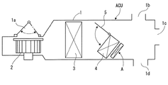
この実施例1の電気ヒータ装置Aは、図1に示す車両用空調ユニットACUに適用されている。   The electric heater device A according to the first embodiment is applied to the vehicle air conditioning unit ACU shown in FIG.

この車両用空調ユニットACUは、ユニットハウジング1の空気取入口1a側から順にブロワファン2、エバポレータ3、ヒータコア4を備えている。また、ヒータコア4の近傍に、エアミックスドア5が設けられ、このエアミックスドア5の開度を調節することで、エバポレータ3を通過した冷気と、ヒータコア4を通過した暖気との混合割合を任意に調節し、各吹出口1b,1c,1dからの吹出空気温度を調節可能に構成されている。   The vehicle air conditioning unit ACU includes a blower fan 2, an evaporator 3, and a heater core 4 in order from the air intake 1 a side of the unit housing 1. In addition, an air mix door 5 is provided in the vicinity of the heater core 4, and the mixing ratio of the cold air that has passed through the evaporator 3 and the warm air that has passed through the heater core 4 can be arbitrarily adjusted by adjusting the opening degree of the air mix door 5. And the temperature of the air blown from each of the air outlets 1b, 1c, 1d is adjustable.

実施例1の電気ヒータ装置Aは、通電することで発熱するもので、ヒータコア4に並設され、ヒータコア4の発熱温度が不十分なときに通電されて発熱するようになっており、例えば、ディーゼル車など図外の推進装置の冷却水が比較的低い車両に用いられる。   The electric heater device A according to the first embodiment generates heat when energized, and is arranged in parallel with the heater core 4, and is energized to generate heat when the heat generation temperature of the heater core 4 is insufficient. Used for vehicles with relatively low cooling water for propulsion devices (not shown) such as diesel vehicles.

以下に、実施例1の電気ヒータ装置Aの詳細について説明する。   Below, the detail of the electric heater apparatus A of Example 1 is demonstrated.

図2に示すように、電気ヒータ装置Aは、ヒータ積層体10の長手方向(矢印CD方向)の両端部に、フロントハウジング(ハウジング部材)20とエンドハウジング(ハウジング部材)30とを装着して形成されている。   As shown in FIG. 2, the electric heater device A has a front housing (housing member) 20 and an end housing (housing member) 30 attached to both ends of the heater laminate 10 in the longitudinal direction (arrow CD direction). Is formed.

ヒータ積層体10は、3つのヒータユニット40,40,40を、その間に支持プレート(位置規制部材)50,50を介在させて上下(この図において矢印LD方向を以下、上下方向と称する)に積み重ね、さらに、その上下にエンドプレート(位置規制部材)60,60を装着して形成されている。   The heater laminate 10 has three heater units 40, 40, 40 vertically arranged with support plates (position regulating members) 50, 50 interposed therebetween (the arrow LD direction in this figure is hereinafter referred to as the vertical direction). It is formed by stacking and mounting end plates (position regulating members) 60, 60 on the top and bottom.

ヒータユニット40は、発熱部材70の上下に放熱フィン部材(放熱部材)80,80を重ねて形成されている。   The heater unit 40 is formed by stacking heat radiating fin members (heat radiating members) 80 and 80 on top and bottom of the heat generating member 70.

なお、放熱フィン部材80は、熱伝導性に優れた金属板材(例えば、アルミやアルミ合金製の板材)により図3に示すように波形状に形成されており、発熱部材70から伝達された熱を、矢印FL方向である幅方向に流れる空気に伝達する。   The heat radiating fin member 80 is formed in a wave shape as shown in FIG. 3 by a metal plate material (for example, a plate material made of aluminum or aluminum alloy) having excellent thermal conductivity, and the heat transferred from the heat generating member 70. Is transmitted to the air flowing in the width direction that is the direction of the arrow FL.

フロントハウジング20およびエンドハウジング30は、電気絶縁性および耐熱性に優れた素材、例えば、繊維強化PBT(Polybutylene terephthalate)などにより形成されている。この繊維強化PBTは、吸水率や熱膨張係数が低いため優れた寸法安定性を示し、また、電気絶縁性にも優れ、吸湿による電気特性の変化が小さく、絶縁破壊電圧が高いという特長を有している。   The front housing 20 and the end housing 30 are formed of a material excellent in electrical insulation and heat resistance, for example, fiber reinforced PBT (Polybutylene terephthalate). This fiber-reinforced PBT has excellent dimensional stability due to its low water absorption coefficient and thermal expansion coefficient, and also has excellent electrical insulation properties, small change in electrical properties due to moisture absorption, and high dielectric breakdown voltage. is doing.

フロントハウジング20には、箱状の積層体差込部21とコネクタ接続部22とが形成されている。   The front housing 20 is formed with a box-shaped laminated body insertion portion 21 and a connector connection portion 22.

積層体差込部21は、図11に示すように、ヒータ積層体10への装着時にヒータ積層体10の一端部を挿入する凹状の挿入用凹部21aが、ヒータ積層体10の積層方向(矢印LD方向)に長く形成されている。また、この挿入用凹部21aには、後述するチューブ差込溝20a、支持プレート差込溝20b、エンドプレート差込溝20c、プレート抜け止め爪20dが形成されている。   As shown in FIG. 11, the laminated body insertion portion 21 includes a concave insertion recess 21 a into which one end of the heater laminated body 10 is inserted when the laminated body 10 is attached to the heater laminated body 10. It is formed long in the LD direction). Further, a tube insertion groove 20a, a support plate insertion groove 20b, an end plate insertion groove 20c, and a plate retaining claw 20d, which will be described later, are formed in the insertion recess 21a.

エンドハウジング30には、ヒータ積層体10への装着時にヒータ積層体10の他端部を挿入する凹状の挿入用凹部31aが、ヒータ積層体10の積層方向(矢印LD方向)に長く形成されている。また、この挿入用凹部31aには、後述するチューブ差込溝30a、支持プレート差込溝30b、エンドプレート差込溝30c、プレート抜け止め爪30dが形成されている。   In the end housing 30, a concave insertion recess 31 a for inserting the other end of the heater laminate 10 when attached to the heater laminate 10 is formed long in the lamination direction of the heater laminate 10 (arrow LD direction). Yes. In addition, a tube insertion groove 30a, a support plate insertion groove 30b, an end plate insertion groove 30c, and a plate retaining claw 30d, which will be described later, are formed in the insertion recess 31a.

また、フロントハウジング20において、 コネクタ接続部22には、電力を供給する図外のコネクタを差し込む差込用凹部22aが形成されている。なお、図14に示すように、積層体差込部21とコネクタ接続部22とは、縦壁23で仕切られているがその詳細については後述する。   Further, in the front housing 20, the connector connecting portion 22 is formed with an insertion recess 22 a into which an unillustrated connector for supplying power is inserted. In addition, as shown in FIG. 14, the laminated body insertion part 21 and the connector connection part 22 are partitioned off by the vertical wall 23, The detail is mentioned later.

次に、上述した発熱部材70、支持プレート50、エンドプレート60について順に詳細に説明する。   Next, the heat generating member 70, the support plate 50, and the end plate 60 described above will be described in detail in order.

発熱部材70は、図4に示すように、ポジションフレーム71と、複数(本実施例1では4個)のPTC素子72と、第1コンタクトシート73および第2コンタクトシート74と、チューブ部材75を備えている。   As shown in FIG. 4, the heating member 70 includes a position frame 71, a plurality (four in this embodiment) of PTC elements 72, a first contact sheet 73 and a second contact sheet 74, and a tube member 75. I have.

ポジションフレーム71は、複数のPTC素子72を長手方向(矢印CD方向)に所定の間隔で並べて配置するもので、絶縁性および耐熱性に優れた素材(例えば、ポリアミドなど)によりプレート状に形成され、図5に示すように、PTC素子72の保持用の切欠部71a,71a,71a,71aが4箇所に形成されている。   The position frame 71 is a plate in which a plurality of PTC elements 72 are arranged in the longitudinal direction (arrow CD direction) at predetermined intervals, and is formed in a plate shape from a material excellent in insulation and heat resistance (for example, polyamide). As shown in FIG. 5, notches 71a, 71a, 71a, 71a for holding the PTC element 72 are formed at four locations.

さらに、ポジションフレーム71の長手方向の両端部には、上下1組の係合爪部材71b,71bが、一体に形成されている。なお、図6は、これら1組の係合爪部材71b,71bを拡大して示しており、ポジションフレーム71の本体から、上下方向にあらかじめ設定された間隔の隙間を空けて配置されている。そして、この隙間に両コンタクトシート73,74をそれぞれ挿入され、これにより、係合爪部材71b,71bが、各コンタクトシート73,74に対し、これらシート73,74がポジションフレーム71が積層方向(矢印LD方向)に離れる相対変位を規制するよう係合されている(図4参照)。   Further, a pair of upper and lower engaging claw members 71b and 71b are integrally formed at both ends of the position frame 71 in the longitudinal direction. FIG. 6 shows the set of engaging claw members 71b and 71b in an enlarged manner, and they are arranged from the main body of the position frame 71 with a gap set in advance in the vertical direction. Then, both contact sheets 73 and 74 are inserted into the gaps, respectively, so that the engaging claw members 71b and 71b are in contact with the contact sheets 73 and 74, respectively. Engagement is performed so as to regulate relative displacement away in the direction of arrow LD (see FIG. 4).

PTC素子72は、一般にPTC(Positive Temperature Coefficient)と称されるチタン酸バリウム(BaTiO3)を主成分とする半導体セラミックで、通電により発熱する特性を有している。なお、本実施例1では、図4に示すように、略長方形の板状に形成されており、ポジションフレーム71の切欠部71aに嵌めこまれて配置されている。   The PTC element 72 is a semiconductor ceramic mainly composed of barium titanate (BaTiO3), generally called PTC (Positive Temperature Coefficient), and has a characteristic of generating heat when energized. In the first embodiment, as shown in FIG. 4, it is formed in a substantially rectangular plate shape, and is disposed by being fitted into the notch 71 a of the position frame 71.

第1コンタクトシート73および第2コンタクトシート74は、図7に示すように、PTC素子72を上下から挟んで配置され、各コンタクトシート73,74を、それぞれ図外の電源のプラスとマイナスとに接続させることで、PTC素子72に通電する。   As shown in FIG. 7, the first contact sheet 73 and the second contact sheet 74 are arranged with the PTC element 72 sandwiched from above and below, and the contact sheets 73 and 74 are respectively connected to the plus and minus of the power source outside the figure. By connecting, the PTC element 72 is energized.

そこで、図外のコネクタに接続するために、図4に示すように、第1コンタクトシート73と第2コンタクトシート74とにおいて、フロントハウジング20が装着される側の端部には、それぞれ第1通電端子76と第2通電端子77とが一体に形成されている。   Therefore, in order to connect to a connector not shown, as shown in FIG. 4, the first contact sheet 73 and the second contact sheet 74 have first end portions on the side where the front housing 20 is mounted, respectively. The energizing terminal 76 and the second energizing terminal 77 are integrally formed.

すなわち、図4(a)に示すように、第1コンタクトシート73の端部(フロントハウジング20が装着される側の端部)は、チューブ部材75の外方まで矢印CD方向に真っ直ぐに延在され、この部分に第1通電端子76が形成されている。   That is, as shown in FIG. 4A, the end portion of the first contact sheet 73 (the end portion on the side where the front housing 20 is mounted) extends straight in the direction of the arrow CD to the outside of the tube member 75. The first energization terminal 76 is formed in this portion.

また、図4(b)に示すように、第2コンタクトシート74のフロントハウジング20が装着される側の端部においてチューブ部材75の外方に延在された部分に第2通電端子77が一体に形成されている。   Further, as shown in FIG. 4B, the second energizing terminal 77 is integrated with a portion extending outward of the tube member 75 at the end of the second contact sheet 74 on the side where the front housing 20 is mounted. Is formed.

さらに、第2通電端子77と第2コンタクトシート74との間には、折曲片(折曲部)77aが設けられている。この折曲片77aは、第2通電端子77と第1通電端子76との間隔を、図外のコネクタ側の端子間隔に一致させるべく第2通電端子77を折曲して形成したものである。したがって、本実施例1では、第2通電端子77は、基端側の折曲片77aと、先端側の端子部77bとにより側方から視て略L字の断面形状に形成され、折曲片77aの図において上下両端位置で略直角に折曲され、端子部77bは、第1通電端子76と略平行に延在されている。   Further, a bent piece (bent portion) 77 a is provided between the second energizing terminal 77 and the second contact sheet 74. The bent piece 77a is formed by bending the second energizing terminal 77 so that the interval between the second energizing terminal 77 and the first energizing terminal 76 matches the terminal interval on the connector side (not shown). . Therefore, in the present Example 1, the 2nd electricity supply terminal 77 is formed in the substantially L-shaped cross-sectional shape seeing from the side by the bending piece 77a of the base end side, and the terminal part 77b of the front end side, and is bent. In the drawing of the piece 77 a, it is bent at substantially right angles at the upper and lower end positions, and the terminal portion 77 b extends substantially in parallel with the first energizing terminal 76.

上述した第1通電端子76は、全ての発熱部材70,70,70に設けられているのに対し、図4に示す形状の第2通電端子77は、図2において上から1番目と2番目の発熱部材70,70に設けられている。   The first energizing terminal 76 described above is provided in all the heat generating members 70, 70, 70, whereas the second energizing terminal 77 having the shape shown in FIG. 4 is the first and second from the top in FIG. The heat generating members 70 are provided.

そして、上から3番目の発熱部材70の第2コンタクトシート74の端部には、図8に示すように、その上に配置された第2通電端子77への圧接を目的とした圧接用通電端子78が設けられているが、その詳細については後述する。   Then, at the end of the second contact sheet 74 of the third heat generating member 70 from the top, as shown in FIG. 8, the energization for press contact for the purpose of press contact with the second energization terminal 77 arranged thereon is provided. A terminal 78 is provided, details of which will be described later.

また、両コンタクトシート73,74は、軽量化および小型化を目的として、その板厚が第1通電端子76および第2通電端子77の端子部77bの板厚の略1/2の厚さに形成されている。すなわち、第1通電端子76および第2通電端子77の端子部77bは、両コンタクトシート73,74の一般部を形成する部分を折り返して重ね合わせて形成されており、これにより、両通電端子76,77は、要求される板厚に形成されている。   Further, for the purpose of reducing the weight and size of the contact sheets 73 and 74, the thickness of the contact sheets 73 and 74 is approximately ½ the thickness of the terminal portions 77b of the first energizing terminal 76 and the second energizing terminal 77. Is formed. That is, the terminal portions 77 b of the first energizing terminal 76 and the second energizing terminal 77 are formed by folding and overlapping the portions forming the general portions of the contact sheets 73 and 74. , 77 are formed to the required plate thickness.

なお、図8に示す圧接用通電端子78は、その全体が、第2コンタクトシート74の一般部と同じ板厚に形成されている。   8 is entirely formed to have the same thickness as that of the general portion of the second contact sheet 74. As shown in FIG.

チューブ部材75は、図7に示すように、上下方向に短い略長方形の筒状に形成され、雄チューブ75aと雌チューブ75bとに上下2分割構造に形成されている。   As shown in FIG. 7, the tube member 75 is formed in a substantially rectangular cylindrical shape that is short in the up-down direction, and is formed in a vertically divided structure on the male tube 75a and the female tube 75b.

雌チューブ75bの開口縁には、係合フランジ75cが開口の内側に向けて折曲されている。   An engagement flange 75c is bent at the opening edge of the female tube 75b toward the inside of the opening.

一方、雄チューブ75aの開口縁には、雌チューブ75bの開口の内側に挿入されて係合フランジ75cと略平行に対向される断面略コの字形状の係合フランジ75dが形成されている。   On the other hand, the opening edge of the male tube 75a is formed with an engagement flange 75d having a substantially U-shaped cross section that is inserted inside the opening of the female tube 75b and faces the engagement flange 75c substantially in parallel.

そして、雄チューブ75aの係合フランジ75dと、雌チューブ75bの係合フランジ75cとを上下方向に係合させた合体状態としたときに、チューブ部材75が筒状に形成される。   When the engagement flange 75d of the male tube 75a and the engagement flange 75c of the female tube 75b are engaged in the up-down direction, the tube member 75 is formed in a cylindrical shape.

また、係合フランジ75cと係合フランジ75dとの間には、両フランジ75c,75dの間隔を拡げる方向に付勢する弾性部材79が圧入されている。この弾性部材79の圧入により発生する弾発力で、雄チューブ75aの一般部と雌チューブ75bの一般部との間隔が、矢印a,aに示すように狭まるよう付勢され、両チューブ75a,75b、両コンタクトシート73,74、PTC素子72の接触圧力が得られる。   In addition, an elastic member 79 that presses in the direction in which the distance between the flanges 75c and 75d is increased is press-fitted between the engagement flange 75c and the engagement flange 75d. The elastic force generated by the press-fitting of the elastic member 79 urges the space between the general portion of the male tube 75a and the general portion of the female tube 75b to become narrow as indicated by arrows a and a, and both tubes 75a, The contact pressure of 75b, both contact sheets 73 and 74, and the PTC element 72 is obtained.

弾性部材79は、樹脂あるいはゴムなどの絶縁性を有した弾性体により形成され、かつ、図7の要部の拡大図である図9に示すように、リップ部79a,79aが一体に形成されている。これらリップ部79a,79aは、各係合フランジ75c,75dの先端面と他方のチューブ75a,75bとの間に挿入され、両チューブ75a,75bが合体状態から分割方向と直交する方向(矢印FL方向)に相対変位したときに、各係合フランジ75c,75dの先端面と他方のチューブ75a,75bとが当接してショートするのを防止する。また、図において、係合フランジ75cの下面と、これに対向する雄チューブ75aとの間隔L1も、確実にショートを防止できる寸法が確保されている。   The elastic member 79 is formed of an insulating elastic material such as resin or rubber, and lip portions 79a and 79a are integrally formed as shown in FIG. 9 which is an enlarged view of the main part of FIG. ing. The lip portions 79a and 79a are inserted between the distal end surfaces of the respective engagement flanges 75c and 75d and the other tubes 75a and 75b, and the tubes 75a and 75b are in the direction perpendicular to the dividing direction from the combined state (arrow FL When the relative displacement is made in the direction), the tip surfaces of the engagement flanges 75c and 75d and the other tubes 75a and 75b are prevented from coming into contact with each other and short-circuiting. In the drawing, the distance L1 between the lower surface of the engagement flange 75c and the male tube 75a facing the lower surface of the engagement flange 75c is also secured to prevent the short circuit.

以上説明した構成の発熱部材70の両端部は、図10に示すエンドハウジング30に形成されたチューブ差込溝30aと、図11に示すフロントハウジング20に形成されたチューブ差込溝20a,20a,20aとに、それぞれ、その先端が図示を省略した溝底部に突き当たるまで差し込まれ、その長手方向(矢印CD方向)および幅方向(矢印FL方向)への移動を規制された状態で支持されている。   Both ends of the heat generating member 70 having the above-described configuration are provided in a tube insertion groove 30a formed in the end housing 30 shown in FIG. 10 and tube insertion grooves 20a, 20a formed in the front housing 20 shown in FIG. 20a is inserted until its tip abuts against a groove bottom (not shown), and supported in a state in which movement in the longitudinal direction (arrow CD direction) and width direction (arrow FL direction) is restricted. .

図2に戻り、支持プレート50は、ヒータユニット40とヒータユニット40との間で、上下に位置する放熱フィン部材80,80を支持する熱伝導性に優れた板材(例えば、アルミ・アルミ合金製の板)製のプレートである。   Returning to FIG. 2, the support plate 50 is a plate (for example, made of aluminum / aluminum alloy) having excellent thermal conductivity that supports the heat dissipating fin members 80, 80 positioned between the heater unit 40 and the heater unit 40. Plate).

この支持プレート50は、図12に示すように帯板状に形成され、長手方向の両端部には、放熱フィン部材80の長手方向の位置を規制する位置規制爪50a,50aが上下に形成されている。   The support plate 50 is formed in a band plate shape as shown in FIG. 12, and position restricting claws 50a and 50a for restricting the longitudinal position of the radiating fin member 80 are formed vertically at both ends in the longitudinal direction. ing.

さらに、支持プレート50において、幅方向(矢印FL方向)の両端縁部には、放熱フィン部材80が幅方向へ移動するのを規制する位置規制フランジ(規制手段)50b,50cが、それぞれ8枚ずつ形成されている。   Further, in the support plate 50, eight position restricting flanges (restricting means) 50b and 50c for restricting the movement of the radiating fin member 80 in the width direction are provided at both end edges in the width direction (arrow FL direction), respectively. It is formed one by one.

これら位置規制フランジ50b,50cは、矢印LDの積層方向の一方である図において上方に折曲された位置規制フランジ50bと、積層方向の他方である図において下方に折曲された位置規制フランジ50cとが形成されている。さらに、これら位置規制フランジ50b,50cは、長手方向で交互に配置され、かつ、矢印FL方向で重なる位置に配置されたものが、その折曲方向が逆となるように配置されている。   The position restricting flanges 50b and 50c are a position restricting flange 50b bent upward in one of the drawings in the stacking direction indicated by the arrow LD, and a position restricting flange 50c bent downward in the other view in the stacking direction. And are formed. Further, these position restricting flanges 50b and 50c are alternately arranged in the longitudinal direction and arranged so as to overlap with each other in the direction of the arrow FL, so that the bending directions are reversed.

この支持プレート50も、長手方向の両端部は、図10に示すエンドハウジング30に形成された支持プレート差込溝30bと、図11に示すフロントハウジング20に形成された支持プレート差込溝20bとに、それぞれ差し込まれ、その長手方向(矢印CD方向)および幅方向(矢印FL方向)への移動を規制された状態で支持されている。   As for this support plate 50, both ends in the longitudinal direction have a support plate insertion groove 30b formed in the end housing 30 shown in FIG. 10, and a support plate insertion groove 20b formed in the front housing 20 shown in FIG. Are supported in a state in which movement in the longitudinal direction (arrow CD direction) and the width direction (arrow FL direction) is restricted.

図2に戻り、エンドプレート60は、ヒータ積層体10の上下端縁を形成する帯板状の金属プレートであって、例えば、亜鉛メッキ鋼板により形成されている。   Returning to FIG. 2, the end plate 60 is a strip-shaped metal plate that forms upper and lower edges of the heater laminate 10, and is formed of, for example, a galvanized steel plate.

このエンドプレート60は、図13に示すように、矢印FL方向の両端縁部に放熱フィン部材80の幅方向(矢印FL方向)への相対移動を規制する位置規制フランジ60a,60aが形成された、略C形状の縦断面形状に形成されている。   As shown in FIG. 13, the end plate 60 is formed with position restriction flanges 60a and 60a for restricting relative movement in the width direction (arrow FL direction) of the radiating fin member 80 at both end edges in the arrow FL direction. , Formed in a substantially C-shaped vertical cross-sectional shape.

また、エンドプレート60の長手方向の両端部には、一組の抜け止め用穴60bおよびフィン規制爪60cが形成されている。抜け止め用穴60bは、略長方形を成してエンドプレート60に穿設されている。   A pair of retaining holes 60b and fin regulating claws 60c are formed at both ends of the end plate 60 in the longitudinal direction. The retaining hole 60b is formed in the end plate 60 in a substantially rectangular shape.

フィン規制爪60cは、位置規制フランジ60aの立ち上げ方向と同方向に切り起こされており、放熱フィン部材80の長手方向の端部に係合して、放熱フィン部材80が矢印CD方向に相対移動するのを規制する。   The fin restricting claw 60c is cut and raised in the same direction as the rising direction of the position restricting flange 60a. The fin restricting claw 60c is engaged with the end of the heat dissipating fin member 80 in the longitudinal direction so that the heat dissipating fin member 80 is relative to the arrow CD direction. Restrict movement.

これらのエンドプレート60は、図10に示すエンドハウジング30に形成されたエンドプレート差込溝30cと、図11に示すフロントハウジング20に形成されたエンドプレート差込溝20cとに、それぞれ差し込まれている。そして、この差込状態で、エンドプレート60の抜け止め用穴60bに、図10に示すエンドハウジング30に形成されたプレート抜け止め爪30d、および図11に示すフロントハウジング20に形成されたプレート抜け止め爪20dが係合されることで、両ハウジング20,30に対してエンドプレート60が長手方向に相対移動するのが規制されている。   These end plates 60 are respectively inserted into an end plate insertion groove 30c formed in the end housing 30 shown in FIG. 10 and an end plate insertion groove 20c formed in the front housing 20 shown in FIG. Yes. In this inserted state, the plate retaining claw 30d formed on the end housing 30 shown in FIG. 10 and the plate retaining formed on the front housing 20 shown in FIG. By engaging the retaining claws 20d, the relative movement of the end plate 60 in the longitudinal direction with respect to both the housings 20 and 30 is restricted.

次に、上述した通電端子76,77および圧接用通電端子78と、フロントハウジング20との関係について説明する。   Next, the relationship between the above-described energization terminals 76 and 77 and the press-contact energization terminal 78 and the front housing 20 will be described.

図14に示すように、積層体差込部21とコネクタ接続部22とを仕切る縦壁23に、各通電端子76,77を差し込む5個の端子挿通穴24,24,24,24,25が上下方向に並んで形成されている。   As shown in FIG. 14, five terminal insertion holes 24, 24, 24, 24, 25 for inserting the respective current-carrying terminals 76, 77 are formed in the vertical wall 23 that partitions the laminated body insertion part 21 and the connector connection part 22. It is formed side by side in the vertical direction.

すなわち、前述したように、3本の発熱部材70のうち、上から3番目の発熱部材70は、図外のコネクタとの接続を目的とする第2通電端子77を有しないことから端子挿通穴24,25の総数は5個となっている。   That is, as described above, among the three heat generating members 70, the third heat generating member 70 from the top does not have the second current-carrying terminal 77 intended for connection with a connector outside the figure, so that the terminal insertion hole The total number of 24 and 25 is 5.

これについて説明を加えると、図15に示すように、3本の発熱部材70のうち、上から3番目に配置された発熱部材70は、上から1番目および2番目の発熱部材70,70とは、上下が逆に配置され、この3番目の発熱部材70の圧接用通電端子78が、上から2番目の発熱部材70の第2通電端子77に圧接され、両者で1つに合体した接続通電端子778が形成されている。そして、図外のコネクタの接続時には、3本の第1通電端子76,76,76が、プラス、マイナスの一方の極性に接続され、第2通電端子77および接続通電端子778が、プラス、マイナスの他方の極性に接続され、圧接用通電端子78も、この第2通電端子77と同じ極性に接続される。   To explain this, as shown in FIG. 15, among the three heat generating members 70, the heat generating member 70 arranged third from the top is the first and second heat generating members 70, 70 from the top. The upper and lower electrodes are arranged upside down, and the current-carrying terminal 78 for pressure contact of the third heat generating member 70 is pressure-contacted to the second current-carrying terminal 77 of the second heat generating member 70 from above, and both are combined into one. An energization terminal 778 is formed. When connecting a connector (not shown), the three first energization terminals 76, 76, and 76 are connected to one of positive and negative polarities, and the second energization terminal 77 and the connection energization terminal 778 are positive and negative. The other contact polarity is also connected, and the press-connecting energizing terminal 78 is also connected to the same polarity as the second energizing terminal 77.

なお、接続通電端子778では、第2通電端子77がコネクタに接続される通電端子として機能するようになっている。   In the connection energization terminal 778, the second energization terminal 77 functions as an energization terminal connected to the connector.

圧接用通電端子78は、図8に示すように、第1通電端子76から離れる方向に立ち上げられた立ち上げ部78aと、この立ち上げ部78aの先端において、第1通電端子76と略平行に延在された当接部78bとを備えた、略逆J形状に形成されている。   As shown in FIG. 8, the press-contact energizing terminal 78 rises in a direction away from the first energizing terminal 76, and the leading end of the rising portion 78 a is substantially parallel to the first energizing terminal 76. And an abutting portion 78b extending in a substantially inverted J shape.

立ち上げ部78aは、図8(b)に示すように、第2コンタクトシート74に対して略直角の角度を成した状態では、当接部78bが、その上方に位置する第2通電端子77の端子部77bに圧接されるだけの長さに形成されている。また、立ち上げ部78aは、フロントハウジング20を装着する前の状態では、図8(a)に示すように、当接部78bが端子部77bに僅かに離れた近接状態となるようその傾斜角度θaが90度よりも小さな角度に設定されている。   As shown in FIG. 8 (b), the rising portion 78 a is at a substantially right angle with respect to the second contact sheet 74, and the contact portion 78 b is positioned above the second energization terminal 77. The terminal portion 77b is formed in such a length as to be press-contacted. Further, as shown in FIG. 8A, the rising portion 78a is inclined so that the contact portion 78b is in a state of being slightly separated from the terminal portion 77b before the front housing 20 is mounted. θa is set to an angle smaller than 90 degrees.

当接部78bは、先端が端子挿通穴25まで達することのない長さに形成され、かつ、端子部77bに接触した際に、線接触状態となるように上方に凸となる湾曲形状に形成されている。   The contact portion 78b is formed in a length that does not reach the terminal insertion hole 25, and has a curved shape that protrudes upward so as to be in a line contact state when contacting the terminal portion 77b. Has been.

図14に戻り、フロントハウジング20の説明を続けると、フロントハウジング20の縦壁23の積層体差込部21において、上から4番目の端子挿通穴25の上側に受圧部としての受圧突片26が図中矢印CD方向に突出して形成され、かつ、その下方位置に押圧部材としての押圧変形用突片27が受圧突片26と略平行に突出して形成されている。   Returning to FIG. 14, the description of the front housing 20 will be continued. In the stacked body insertion portion 21 of the vertical wall 23 of the front housing 20, a pressure receiving protrusion 26 as a pressure receiving portion is provided above the fourth terminal insertion hole 25 from the top. Is formed so as to project in the direction of the arrow CD in the figure, and a pressing deformation projecting piece 27 as a pressing member is formed so as to project substantially parallel to the pressure receiving projecting piece 26 at a lower position.

受圧突片26は、図8(b)に示す組付状態で、上から2番目の発熱部材70の第2通電端子77の端子部77bの上面に沿って配置されるよう形成され、かつ、先端下側に、斜め下向きのガイド面26aが形成されている。   The pressure receiving protrusion 26 is formed so as to be disposed along the upper surface of the terminal portion 77b of the second energizing terminal 77 of the second heating member 70 from the top in the assembled state shown in FIG. An obliquely downward guide surface 26a is formed on the lower side of the tip.

なお、受圧突片26に隣接される端子挿通穴25を除いた他の端子挿通穴24には、積層体差込部21側の上下に、ガイド面24a,24aが形成されている。そして、受圧突片26に隣設される端子挿通穴25には、下側のみにガイド面25aが形成されている。   In addition, guide surfaces 24 a and 24 a are formed on the upper and lower sides of the laminated body insertion portion 21 in the other terminal insertion holes 24 excluding the terminal insertion holes 25 adjacent to the pressure receiving protrusions 26. In the terminal insertion hole 25 provided adjacent to the pressure receiving protrusion 26, a guide surface 25a is formed only on the lower side.

さらに、ヒータ積層体10には、図16に示すように、各発熱部材70のフロントハウジング20を装着する側の端部に、ストッパ部材90が装着されている。   Furthermore, as shown in FIG. 16, a stopper member 90 is attached to the heater laminate 10 at the end of each heat generating member 70 on the side where the front housing 20 is attached.

このストッパ部材90は、両ハウジング20,30と同様に、繊維強化PBTなどのように、電気絶縁性および耐熱性に優れた素材により形成され、図17に示すように、3つの挟持部91,91,91を2本のロッド部92,92で結合した形状に一体に形成されている。   This stopper member 90 is formed of a material excellent in electrical insulation and heat resistance, such as fiber reinforced PBT, as in the case of the housings 20 and 30, and as shown in FIG. 91 and 91 are integrally formed in a shape in which two rod portions 92 and 92 are coupled.

挟持部91は、挿入空間91aを挟んで上下に対向して配置された一対の挟持片91b,91bと、各挟持片91b,91bの一端を連続させた押え片91cと、が一体に形成された略コの字断面形状に形成されている。挿入空間91aは、発熱部材70の端部であって、チューブ部材75の先端から突出された部分、すなわち、ポジションフレーム71の上下両側に両コンタクトシート73,74が重なっている部分を挟持可能な間隔に形成されている。そして、各挟持片91bの先端部には、挿入空間91aに発熱部材70を挿入させた際に、発熱部材70の端縁に係合する係合爪91dが形成されている。   The sandwiching portion 91 is integrally formed with a pair of sandwiching pieces 91b and 91b that are arranged vertically opposite to each other with the insertion space 91a interposed therebetween, and a pressing piece 91c in which one end of each sandwiching piece 91b and 91b is continuous. It is formed in a substantially U-shaped cross-sectional shape. The insertion space 91a is an end portion of the heat generating member 70 and can sandwich a portion protruding from the tip of the tube member 75, that is, a portion where both the contact sheets 73 and 74 overlap on both upper and lower sides of the position frame 71. It is formed at intervals. An engaging claw 91d that engages with the edge of the heat generating member 70 when the heat generating member 70 is inserted into the insertion space 91a is formed at the tip of each clamping piece 91b.

したがって、挿入空間91aに発熱部材70の端部を挿入させたときに、発熱部材70は、押え片91cと係合爪91d,91dとにより、幅方向(矢印FL方向)の相対移動が規制される。   Therefore, when the end of the heat generating member 70 is inserted into the insertion space 91a, the heat generating member 70 is restricted from relative movement in the width direction (arrow FL direction) by the holding piece 91c and the engaging claws 91d and 91d. The

ストッパ部材90のロッド部92は、断面が長方形の四角柱状に形成され、フロントハウジング20側を向く一側面には、挟持部91と面一に形成された平面状のストッパ面92aが形成されている。   The rod portion 92 of the stopper member 90 is formed in a rectangular column shape having a rectangular cross section, and a flat stopper surface 92a formed flush with the clamping portion 91 is formed on one side surface facing the front housing 20 side. Yes.

ストッパ部材90は、図16に示すように各挟持部91に発熱部材70の端部を挿入させたチューブ装着状態において、挟持部91が、ポジションフレーム71の係合爪部材71bに、長手方向(矢印CD方向)で係合し、かつ、この状態で、ストッパ面92aが、第2通電端子77の折曲片77aに当接するよう形成されている。   In the tube mounting state in which the end portions of the heat generating members 70 are inserted into the respective holding portions 91 as shown in FIG. 16, the holding portions 91 are connected to the engaging claw members 71 b of the position frame 71 in the longitudinal direction ( The stopper surface 92a is formed so as to abut against the bent piece 77a of the second energizing terminal 77 in this state.

次に、実施例1の電気ヒータ装置Aの組立手順を説明する。   Next, the assembly procedure of the electric heater device A according to the first embodiment will be described.

まず、図外の治具などを用いて、下から順にエンドプレート60、放熱フィン部材80、発熱部材70、放熱フィン部材80、支持プレート50、放熱フィン部材80、発熱部材70、放熱フィン部材80、支持プレート50、放熱フィン部材80、発熱部材70、放熱フィン部材80、エンドプレート60と積み重ねてヒータ積層体10を形成する。  First, using an unillustrated jig or the like, the end plate 60, the radiating fin member 80, the heat generating member 70, the heat radiating fin member 80, the support plate 50, the heat radiating fin member 80, the heat generating member 70, and the heat radiating fin member 80 in order from the bottom. The heater laminate 10 is formed by stacking the support plate 50, the radiating fin member 80, the heat generating member 70, the radiating fin member 80, and the end plate 60.

次に、このヒータ積層体10の一端に、図15に示すようにエンドハウジング30を装着し、その後、ヒータ積層体10の発熱部材70,70,70の他端に、ストッパ部材90を装着し、最後に、フロントハウジング20を装着して組み付けを終了する。   Next, the end housing 30 is attached to one end of the heater laminate 10 as shown in FIG. 15, and then the stopper member 90 is attached to the other end of the heating members 70, 70, 70 of the heater laminate 10. Finally, the front housing 20 is mounted to complete the assembly.

このフロントハウジング20の組み付け時に、図16において、上から3番目に示す発熱部材70の圧接用通電端子78は、接続通電端子778を構成する第2通電端子77に接触され、さらに、その接触圧力を高める変形が成される。   When the front housing 20 is assembled, the pressure contact energizing terminal 78 of the heat generating member 70 shown in the third from the top in FIG. 16 is brought into contact with the second energizing terminal 77 constituting the connection energizing terminal 778, and the contact pressure thereof. The deformation which raises is made.

ここで、接続通電端子778における圧接用通電端子78の変形動作について説明を加える。   Here, the deformation operation of the pressure contact energizing terminal 78 in the connection energizing terminal 778 will be described.

第2通電端子77の折曲片77aが略直角に立ち上げられているのに対し、この圧接用通電端子78の立ち上げ部78aは、当初の傾斜角度θaが、図8に示すように90度よりも小さな角度に形成されている。   The bent portion 77a of the second energizing terminal 77 is raised at a substantially right angle, whereas the rising portion 78a of the energizing terminal 78 for pressure contact has an initial inclination angle θa of 90 as shown in FIG. It is formed at an angle smaller than degrees.

すなわち、ヒータ積層体10の組付時には、各通電端子76,77は、フロントハウジング20の縦壁23に設けられた各端子挿通穴24,25の間隔と一致する間隔に配置される。このヒータ積層体10の組付状態において、立ち上げ部78aは傾斜角度θaで傾斜しており、圧接用通電端子78の当接部78bは、その上方に配置された第2通電端子77に近接されている。   That is, when the heater laminate 10 is assembled, the energization terminals 76 and 77 are arranged at intervals that match the intervals between the terminal insertion holes 24 and 25 provided in the vertical wall 23 of the front housing 20. In the assembled state of the heater laminate 10, the rising portion 78a is inclined at an inclination angle θa, and the abutting portion 78b of the energizing terminal 78 for press contact is close to the second energizing terminal 77 disposed above it. Has been.

この状態では、立ち上げ部78aは、弾性変形されていないことから、圧接用通電端子78の両側に配置される両通電端子76,77に対して、その間隔を拡げる弾性力が作用しないため、これらの通電端子76,77の間隔を、各端子挿通穴24,25の間隔に保持するための専用の工具や工程を必要としない。   In this state, since the rising portion 78a is not elastically deformed, an elastic force that widens the interval does not act on the two energizing terminals 76 and 77 arranged on both sides of the press-contact energizing terminal 78. There is no need for a dedicated tool or process for maintaining the interval between the energizing terminals 76 and 77 at the interval between the terminal insertion holes 24 and 25.

そこで、図15に示すように、ヒータ積層体10の一端にエンドハウジング30を装着したら、次に、ヒータ積層体10の他端に、フロントハウジング20を矢印CD方向へ移動させながら装着する。   Therefore, as shown in FIG. 15, when the end housing 30 is attached to one end of the heater laminate 10, next, the front housing 20 is attached to the other end of the heater laminate 10 while moving in the arrow CD direction.

このとき、ヒータ積層体10から突出している各通電端子76,77を、フロントハウジング20の端子挿通穴24,25に挿通させるが、各通電端子76,77の位置と、各端子挿通穴24,25の位置とが、上下方向で多少ずれていても、各端子挿通穴24のガイド面24a,24aおよび端子挿通穴25のガイド面25aおよび受圧突片26のガイド面26aでガイドされて、スムーズに差し込まれる。   At this time, the current-carrying terminals 76 and 77 projecting from the heater laminate 10 are inserted into the terminal insertion holes 24 and 25 of the front housing 20, but the positions of the current-carrying terminals 76 and 77 and the terminal insertion holes 24 and 25 Even if the position 25 is slightly deviated in the vertical direction, it is smoothly guided by the guide surfaces 24a and 24a of each terminal insertion hole 24, the guide surface 25a of the terminal insertion hole 25, and the guide surface 26a of the pressure receiving protrusion 26. Plugged into.

そして、各通電端子76,77を、端子挿通穴24,25に挿通させると、図8に示すように、押圧変形用突片27の先端面が、圧接用通電端子78の立ち上げ部78aを押し、その傾斜角度θaを立ち上げる方向に弾性変形させる。この弾性変形により圧接用通電端子78の当接部78bが、接続通電端子778を構成する第2通電端子77の端子部77bに圧接される。   When the energization terminals 76 and 77 are inserted into the terminal insertion holes 24 and 25, as shown in FIG. 8, the leading end surface of the pressing deformation projecting piece 27 has the rising portion 78 a of the press-contact energization terminal 78. Press and elastically deform the tilt angle θa in the rising direction. Due to this elastic deformation, the abutting portion 78 b of the pressure contact energizing terminal 78 is brought into pressure contact with the terminal portion 77 b of the second energizing terminal 77 constituting the connection energizing terminal 778.

さらに、この第2通電端子77の端子部77bの上側には、受圧突片26が当接状態で配置されているため、この圧接で第2通電端子77の端子部77bが変形するのが防止され、上記の圧接用通電端子78の変形ならびに圧接が確実に成される。   Further, since the pressure receiving protrusion 26 is disposed in contact with the upper side of the terminal portion 77b of the second energizing terminal 77, the terminal portion 77b of the second energizing terminal 77 is prevented from being deformed by this pressure contact. Thus, deformation and pressure contact of the pressure contact energizing terminal 78 are ensured.

なお、押圧変形用突片27は、その矢印CD方向の寸法が、図8(b)に示す組付終了時に、圧接用通電端子78の傾斜角度θbが、略直角となる寸法に設定されている。   Note that the pressing deformation projecting piece 27 is set such that the dimension in the direction of the arrow CD is such that the inclination angle θb of the pressure contact energizing terminal 78 is substantially perpendicular at the end of assembly shown in FIG. Yes.

また、このとき、発熱部材70には、ストッパ部材90が装着されており、押圧変形用突片27から圧接用通電端子78に対する矢印CD方向への入力が、ストッパ部材90のストッパ面92aで受け止められ、圧接用通電端子78が、過大に変形することが防止される。ちなみに、ストッパ部材90への入力は、このストッパ部材90が係合された発熱部材70のポジションフレーム71がエンドハウジング30に突き当てられていることで、エンドハウジング30で受け止められる。   At this time, the heating member 70 is mounted with the stopper member 90, and the input in the arrow CD direction from the pressing deformation projecting piece 27 to the pressure contact energizing terminal 78 is received by the stopper surface 92 a of the stopper member 90. Thus, the pressure contact energizing terminal 78 is prevented from being excessively deformed. Incidentally, the input to the stopper member 90 is received by the end housing 30 because the position frame 71 of the heat generating member 70 with which the stopper member 90 is engaged is abutted against the end housing 30.

以上のようにして組み立てられた実施例1の電気ヒータ装置Aには、図外のコネクタが接続される。このコネクタの接続の際には、各通電端子76,77に対して矢印CD方向に入力を受ける。このとき、第1通電端子76は、第1コンタクトシート73と直線状に連続して形成されていることから、この入力は、他端のエンドハウジング30で受け止められる。   A connector (not shown) is connected to the electric heater device A of Example 1 assembled as described above. When this connector is connected, an input is received in the direction of the arrow CD with respect to the energization terminals 76 and 77. At this time, since the first energization terminal 76 is formed linearly and continuously with the first contact sheet 73, this input is received by the end housing 30 at the other end.

一方、第2通電端子77は、L字状に折曲された折曲片77aを有しており、第2通電端子77の端子部77bへの矢印CD方向への入力は、折曲片77aに対して立ち上げ角度を深くする方向に作用する。ここで、本実施例1では、第2通電端子77の折曲片77aの背面にストッパ部材90のストッパ面92aが接して設けられているため、折曲片77aに作用する力をストッパ部材90で受け止め、折曲片77aが変形するのが防止される。   On the other hand, the second energizing terminal 77 has a bent piece 77a bent in an L shape, and the input in the arrow CD direction to the terminal portion 77b of the second energizing terminal 77 is the bent piece 77a. Acts in the direction of increasing the startup angle. Here, in the first embodiment, since the stopper surface 92a of the stopper member 90 is provided in contact with the back surface of the bent piece 77a of the second energizing terminal 77, the force acting on the bent piece 77a is applied to the stopper member 90. And the bent piece 77a is prevented from being deformed.

これにより、第2通電端子77の折曲片77aの変形を原因とした接触不良の発生を防止できる。   Thereby, it is possible to prevent the occurrence of contact failure due to the deformation of the bent piece 77a of the second energizing terminal 77.

以上説明したように、実施例1の電気ヒータ装置にあっては、3つの発熱部材70に設けられた合計6枚の第1・第2コンタクトシート73,74への電気的接続を、合計5本の第1・第2通電端子76,77で行うようにして、接続に要するスペースの小型化を図るとともに、各通電端子76,77間の距離を確保している。   As described above, in the electric heater device according to the first embodiment, a total of five electrical connections to the first and second contact sheets 73 and 74 provided on the three heat generating members 70 are provided. As in the case of the first and second energization terminals 76 and 77 of the book, the space required for connection is reduced, and the distance between the energization terminals 76 and 77 is secured.

さらに、第2通電端子77の数を減らすのにあたり、本実施例1では、上から3番目の発熱部材70の第2コンタクトシート74に、上から2番目の発熱部材70の第2通電端子77へ圧接させる圧接用通電端子78を設け、しかも、両者の圧接が、フロントハウジング20の装着作業に伴って成されるようにした。   Furthermore, in order to reduce the number of second energization terminals 77, in the first embodiment, the second contact sheet 74 of the third heat generating member 70 from the top is connected to the second energization terminal 77 of the second heat generating member 70 from the top. A pressure contact energizing terminal 78 is provided for pressure contact with each other, and the pressure contact between the two is performed in accordance with the mounting operation of the front housing 20.

このため、圧接用通電端子78と第2通電端子77とをあらかじめ溶接により接続させたり、両者を接続用の部品を用いて接続させたりする場合と比較して、作業工数や部品点数を減らして、作業性および経済性に優れる。   For this reason, compared with the case where the current-carrying terminal 78 for pressure welding and the second current-carrying terminal 77 are connected in advance by welding, or both are connected using connecting parts, the work man-hours and the number of parts are reduced. Excellent workability and economy.

また、ヒータ積層体10を形成した時点で、圧接用通電端子78と第2通電端子77とを圧接させる場合と比較しても、専用の部品や手間を省くことができる。すなわち、ヒータ積層体10を形成した時点で、圧接用通電端子78と第2通電端子77とを圧接させる場合、図18(a)に示すように、本来、端子挿通穴24,24の間隔よりも広がっている第2通電端子77および第1接続用端子76の間隔を、同図(b)に示すように、端子挿通穴24,24の間隔に一致するように、圧接用通電端子78を弾性変形させることで圧接させる必要がある。この図18(b)に示す状態では、圧接用通電端子78を弾性変形させたことによる復元力で、これらを有した発熱部材70,70が離れようとするため、これを規制して圧接用通電端子78が弾性変形された状態に維持する専用の部品や工具が必要になるとともに、そのための作業が必要となる。   In addition, when the heater laminate 10 is formed, it is possible to save dedicated parts and labor compared to the case where the press-contacting current-carrying terminal 78 and the second current-carrying terminal 77 are pressed. That is, in the case where the pressure contact energizing terminal 78 and the second energizing terminal 77 are brought into pressure contact with each other when the heater laminated body 10 is formed, as shown in FIG. The energizing terminal 78 for pressure contact is set so that the distance between the second energizing terminal 77 and the first connecting terminal 76 that is also wide is equal to the distance between the terminal insertion holes 24 and 24 as shown in FIG. It is necessary to press contact by elastic deformation. In the state shown in FIG. 18 (b), the heat generating members 70, 70 having these are about to be separated by the restoring force generated by elastically deforming the pressure contact energizing terminal 78. A dedicated component or tool for maintaining the energization terminal 78 in an elastically deformed state is required, and work for that purpose is required.

本実施例1では、フロントハウジング20の装着時に、この圧接用通電端子78を変形させることで圧接させるため、フロントハウジング20の装着前の時点で圧接用通電端子78の弾性変形状態を維持させることが不要であるため、このための専用部品や工具やその作業が不要で、作業性に優れ、かつ経済性にも優れる。   In the first embodiment, when the front housing 20 is mounted, the pressure contact energizing terminal 78 is pressed to be deformed, so that the elastic state of the pressure contact energizing terminal 78 is maintained before the front housing 20 is mounted. Therefore, the dedicated parts and tools for that purpose and the work thereof are unnecessary, and the workability is excellent and the economy is also excellent.

しかも、実施例1では、上述のように圧接用通電端子78の弾性変形は、その立ち上げ部78aの傾斜角度が大きくなる弾性変形でおこなうようにしたため、圧接用通電端子78が圧接された状態と圧接されない状態とが、フロントハウジング20の装着作業方向で形成することが容易となり、上述の作業性および経済性に優れる効果を、容易に発揮することができる。   Moreover, in the first embodiment, as described above, since the elastic deformation of the pressure contact energizing terminal 78 is performed by the elastic deformation in which the inclination angle of the rising portion 78a is increased, the pressure contact energizing terminal 78 is in pressure contact. It is easy to form a state in which the front housing 20 is not in pressure contact with the mounting operation direction of the front housing 20, and the above-described effects of excellent workability and economy can be easily exhibited.

加えて、実施例1では、フロントハウジング20の押圧変形用突片27が圧接用通電端子78を弾性変形させて、圧接用通電端子78が第2通電端子77に圧接されたときに、第2通電端子78の上面に沿って配置された受圧突片26が、この圧接力を受圧する。   In addition, in the first embodiment, when the pressing deformation projecting piece 27 of the front housing 20 elastically deforms the pressure contact energizing terminal 78 and the pressure contact energizing terminal 78 is pressed against the second current energizing terminal 77, the second The pressure receiving protrusions 26 arranged along the upper surface of the energizing terminal 78 receive this pressure contact force.

よって、接続通電端子778の第2通電端子77が圧接用通電端子78の圧接力で変形するのを防止することができ、この変形を原因とする接触不良などの不具合の発生を防止することができる。   Therefore, it is possible to prevent the second energization terminal 77 of the connection energization terminal 778 from being deformed by the pressure contact force of the pressure contact energization terminal 78, and it is possible to prevent the occurrence of problems such as poor contact due to this deformation. it can.

さらに、圧接用通電端子78は、他の通電端子76,77に比べて、板厚を薄く形成しているため、圧接用通電端子78を弾性変形させて圧接させる作業を容易に行うことができる。   Furthermore, since the press contact energizing terminal 78 is formed thinner than the other energizing terminals 76 and 77, the operation of making the press contact energizing terminal 78 elastically deformed and press contacting can be easily performed. .

また、実施例1では、筒状のチューブ部材75にプラス用およびマイナス用の第1・第2コンタクトシート73,74とPTC素子72とを挿入した発熱部材70を用い、PTC素子72の必要な電気的な接触は、この発熱部材70内で行うようにした。   In the first embodiment, the heat generating member 70 in which the first and second contact sheets 73 and 74 for plus and minus and the PTC element 72 are inserted into the tubular tube member 75 is used, and the PTC element 72 is required. Electrical contact was made within the heat generating member 70.

したがって、放熱フィン部材80などの放熱用の部材を電極として用いるのに比べて、他の金属部材などが接触してショートなどが発生する不具合を回避しやすくなる。   Therefore, it is easier to avoid a problem that a short circuit or the like occurs due to contact with other metal members, compared to the case where a heat radiating member such as the heat radiating fin member 80 is used as an electrode.

また、チューブ部材75に第1・第2コンタクトシート73,74を挿入しているが、第2通電端子77をL字状に折曲させているため、両通電端子76,77どうしの接触による不具合が生じにくい。さらに、圧接用通電端子78との圧接が容易となるとともに、圧接用通電端子78の弾性変形代の確保も容易となる。   In addition, the first and second contact sheets 73 and 74 are inserted into the tube member 75, but the second energizing terminal 77 is bent in an L shape, so that the energizing terminals 76 and 77 are in contact with each other. Defects are less likely to occur. Further, the pressure contact with the pressure contact energizing terminal 78 is facilitated, and the elastic deformation allowance of the pressure contact energizing terminal 78 is easily secured.

加えて、実施例1では、放熱フィン部材80の幅方向(矢印FL方向)の抜け止めは、図12に示す支持プレート50に形成された位置規制フランジ50b,50c、および図13に示すエンドプレート60の位置規制フランジ60a,60aにより行うようにして、発熱部材70には、熱交換する空気の流れを妨げるフランジを設けない構成とした。   In addition, in the first embodiment, the radiating fin member 80 is prevented from coming off in the width direction (arrow FL direction) by the position regulating flanges 50b and 50c formed on the support plate 50 shown in FIG. 12, and the end plate shown in FIG. As in the case of the 60 position regulating flanges 60a, 60a, the heat generating member 70 is configured not to be provided with a flange that obstructs the flow of air for heat exchange.

このように、放熱フィン部材80の空気流との接触を妨げる構成が、放熱フィン部材80において熱源である発熱部材70から最も離れた部位に配置されており、放熱フィン部材80の熱源である発熱部材70に接している部位には、この空気流の妨げとなるものがない。   Thus, the structure which prevents the radiation fin member 80 from coming into contact with the air flow is disposed at a position farthest from the heat generating member 70 which is a heat source in the heat radiation fin member 80, and the heat generation which is a heat source of the heat radiation fin member 80. There is nothing that obstructs the air flow at the portion in contact with the member 70.

よって、放熱フィン部材80の抜け止め用のフランジを発熱部材70側に形成する場合と比較して、放熱フィン部材80の熱交換効率が向上する。   Therefore, the heat exchange efficiency of the radiating fin member 80 is improved as compared with the case where a flange for preventing the radiating fin member 80 from being removed is formed on the heat generating member 70 side.

さらに、本実施例1では、ヒータ積層体10を形成するにあたり、1つの発熱部材70を一対の放熱フィン部材80,80で挟んで形成したヒータユニット40を、3つ積層してヒータ積層体10を形成している。このように構成することで、各ヒータユニット40において、1つの発熱部材70で発生させた熱を、2つの放熱フィン部材80,80に伝達させて効率的に放熱することができる。このような構成では、ヒータユニット40どうしを積み重ねたときに、両ユニット40の間で、両ユニット40を支持する部材(支持プレート50)が必要になるが、本実施例1では、この支持プレート50を有効に利用して放熱フィン部材80の抜け止めを行うようにしており、これらの機能を別々に設けるものと比較して、部品点数を削減して、組付工数、製造コスト、重量の削減および小型化を図ることが可能となる。   Further, in the first embodiment, when the heater laminated body 10 is formed, three heater units 40 formed by sandwiching one heat generating member 70 between a pair of radiating fin members 80 and 80 are laminated to form the heater laminated body 10. Is forming. With this configuration, in each heater unit 40, the heat generated by one heat generating member 70 can be transmitted to the two heat radiating fin members 80 and 80 and efficiently radiated. In such a configuration, when the heater units 40 are stacked, a member (support plate 50) for supporting both units 40 is required between the two units 40. In the first embodiment, this support plate is used. 50 is effectively used to prevent the radiating fin member 80 from being removed. Compared with a case where these functions are provided separately, the number of parts is reduced, and the assembly man-hours, manufacturing cost, and weight are reduced. Reduction and downsizing can be achieved.

しかも、本実施例1では、放熱フィン部材80の幅方向の移動を規制する位置規制フランジ50b,50c,60aを、それぞれ支持プレート50およびエンドプレート60に一体に形成したため、この移動を規制する手段を、これらのプレートに別体に設けるのと比較して、部品点数を削減して、組付工数、製造コスト、重量の削減および小型化を図ることが可能となる。   In addition, in the first embodiment, the position restricting flanges 50b, 50c, 60a for restricting the movement of the radiating fin member 80 in the width direction are formed integrally with the support plate 50 and the end plate 60, respectively. Can be reduced in number of parts compared with the case where these plates are provided separately on these plates, thereby reducing the number of assembling steps, manufacturing costs, weight, and size.

加えて、本実施例1では、支持プレート50に位置規制フランジ50b,50cを形成するのにあたり、フランジの起立方向を積層方向で正逆異ならせたものを、交互に形成したため、1枚の板材のプレス加工で、上下の両方に隣設される放熱フィン部材80,80の抜け止めを防止することができる。これにより、部品点数を削減して、よりいっそう組付工数、製造コスト、重量の削減および小型化を図ることが可能となる。   In addition, in the first embodiment, when the position restricting flanges 50b and 50c are formed on the support plate 50, the ones in which the rising directions of the flanges are different from each other in the stacking direction are alternately formed. In the pressing process, it is possible to prevent the radiating fin members 80 and 80 adjacent to both the upper and lower sides from being detached. As a result, it is possible to reduce the number of parts and further reduce the assembly man-hours, manufacturing cost, weight, and size.

さらに、本実施例1では、発熱部材70にストッパ部材90を装着し、L字状に折曲された第2通電端子77および圧接用通電端子78の折曲片77aおよび立ち上げ部78aの裏面にストッパ面92aを当接あるいは近接させて配置した。これにより、圧接用通電端子78の圧接作業時、およびコネクタの接続作業時に、第2通電端子77および圧接用通電端子78に対して、矢印CD方向に荷重が入力されても、折曲片77aおよび立ち上げ部78aが過大に折り曲げられる変形が生じるのを防止できる。   Further, in the first embodiment, a stopper member 90 is mounted on the heat generating member 70, the second energizing terminal 77 bent in an L shape, the bent piece 77a of the press-contact energizing terminal 78, and the back surface of the rising portion 78a. The stopper surface 92a is disposed in contact with or in close proximity to. As a result, even when a load is applied in the direction of the arrow CD to the second energizing terminal 77 and the pressing energizing terminal 78 during the pressing operation of the pressing energizing terminal 78 and the connector connecting operation, the bent piece 77a. Further, it is possible to prevent the riser 78a from being deformed by being excessively bent.

よって、この変形により接続不良の発生を防止できる。特に、本実施例1では、軽量化のために、各コンタクトプレー73,74として、各通電端子76,77よりも板厚が薄いものを用いており、圧接用通電端子78の立ち上げ部78aの板厚が薄くなっているが、このような構成において特に有効となる。   Therefore, the occurrence of poor connection can be prevented by this deformation. In particular, in the first embodiment, in order to reduce the weight, each contact play 73, 74 is thinner than each energizing terminal 76, 77, and the rising portion 78a of the energizing terminal 78 for press contact is used. This is particularly effective in such a configuration.

しかも、ヒータ積層体10を組み付けた際に、3本の発熱部材70,70,70のフロントハウジング20側の端部の積層方向(矢印LD方向)の位置が、ストッパ部材90により位置決めされるようにした。このため、各通電端子76,77の間隔も、所定の間隔に保持され、これらの通電端子76,77を各端子挿通穴24,25に挿通させるのがスムーズになり、ストッパ部材90を設けない場合に比べて、フロントハウジング20の装着作業をスムーズに行うことができる。   Moreover, when the heater laminate 10 is assembled, the position of the end portions of the three heat generating members 70, 70, 70 on the front housing 20 side in the stacking direction (arrow LD direction) is positioned by the stopper member 90. I made it. For this reason, the intervals between the current-carrying terminals 76 and 77 are also maintained at predetermined intervals, and it is smooth to insert the current-carrying terminals 76 and 77 into the terminal insertion holes 24 and 25, and the stopper member 90 is not provided. Compared to the case, the mounting operation of the front housing 20 can be performed smoothly.

また、本実施例1では、発熱部材70のチューブ部材75として、雄チューブ75aと雌チューブ75bとの2分割構造のものを用い、両チューブ75a,75bの間に介在されて付勢する弾性部材79を絶縁性を有する素材で形成し、さらに、第1・第2コンタクトシート73,74を両チューブ75a,75bに直接接触させて、これらの少なくとも一方の間に介在させていた絶縁体を廃止した。   In the first embodiment, the tube member 75 of the heat generating member 70 is a two-part structure of a male tube 75a and a female tube 75b, and is an elastic member that is interposed between the tubes 75a and 75b and biases it. 79 is made of an insulating material, and the first and second contact sheets 73 and 74 are brought into direct contact with both the tubes 75a and 75b, thereby eliminating the insulator interposed between at least one of them. did.

このため、発熱部材70の構成部品点数を抑えて、コストおよび組付工数の低減を図ることができる。   For this reason, the number of components of the heat generating member 70 can be suppressed, and the cost and the number of assembling steps can be reduced.

さらに、発熱部材70板厚(図7の寸法L2)を抑えて、発熱部材70ならびに電気ヒータ装置Aの薄型化を図ることができる。あるいは、装置が同じサイズであれば、放熱フィン部材80の寸法を相対的に大きくして、熱交換効率の向上を図ることができる。   Furthermore, the thickness of the heat generating member 70 and the electric heater device A can be reduced by suppressing the plate thickness of the heat generating member 70 (dimension L2 in FIG. 7). Or if a device is the same size, the dimension of the radiation fin member 80 can be enlarged relatively, and the improvement of heat exchange efficiency can be aimed at.

加えて、第1・第2コンタクトシート73,74を両チューブ75a,75bに直接接触させたことにより、熱伝達性能を向上させてエネルギ効率の向上を図ることが可能となる。   In addition, since the first and second contact sheets 73 and 74 are in direct contact with both the tubes 75a and 75b, it is possible to improve heat transfer performance and improve energy efficiency.

また、接続通電端子778では、第2通電端子77のみを端子挿通穴25に挿通させるため、接続通電端子778の通電用の端子を、他の通電端子76,77と同じ板厚に形成でき、製造が容易となる。   Further, in the connection energization terminal 778, only the second energization terminal 77 is inserted into the terminal insertion hole 25, so that the energization terminal of the connection energization terminal 778 can be formed with the same plate thickness as the other energization terminals 76 and 77. Manufacturing is easy.

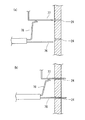
次に、図19に基づいてこの発明の実施の形態の実施例2の電気ヒータ装置について説明する。なお、この実施例2は、実施例1の変形例であるため、その相違点についてのみ説明し、実施例1と同様の構成および作用効果については説明を省略する。   Next, an electric heater device according to Example 2 of the embodiment of the present invention will be described with reference to FIG. Since the second embodiment is a modification of the first embodiment, only the difference will be described, and the description of the same configuration and operational effects as the first embodiment will be omitted.

実施例2は、位置規制部材としての支持プレート250の構成が実施例1と異なる。この支持プレート250は、エンドプレート60と同様に、幅方向の両端縁部に長手方向の全長に亘る位置規制フランジ251a,252aを有した部材251,252を2枚結合させて形成されている。   The second embodiment is different from the first embodiment in the configuration of the support plate 250 as a position regulating member. Similar to the end plate 60, the support plate 250 is formed by joining two members 251 and 252 having position restricting flanges 251a and 252a extending over the entire length in the longitudinal direction at both end edges in the width direction.

なお、位置規制フランジ251a,252aは、支持プレート250の前長に亘って一枚の板状に形成してもよいが、例えば、図(b)に示すように、途中に切欠部251a,252bを形成して、熱交換用の空気の流れを妨げにくい構造としてもよい。   The position restricting flanges 251a and 252a may be formed in a single plate shape over the front length of the support plate 250. For example, as shown in FIG. It is good also as a structure which is hard to prevent the flow of the air for heat exchange.

また、支持プレート250を樹脂により形成した場合には、部材251,252を一部材で形成することができ、部品点数を削減することができる。   Further, when the support plate 250 is formed of resin, the members 251 and 252 can be formed as a single member, and the number of parts can be reduced.

他の構成は、実施例1と同様であるから説明を省略する。   Other configurations are the same as those of the first embodiment, and thus the description thereof is omitted.

以上、図面を参照して、本発明の実施の形態および実施例1,2を詳述してきたが、具体的な構成は、この実施の形態および実施例1に限らず、本発明の要旨を逸脱しない程度の設計的変更は、本発明に含まれる。   The embodiment of the present invention and Examples 1 and 2 have been described above in detail with reference to the drawings. However, the specific configuration is not limited to this embodiment and Example 1, and the gist of the present invention is described. Design changes that do not deviate are included in the present invention.

例えば、実施例1,2では、ヒータ積層体10としてヒータユニット40を3段重ねして形成した例を示したが、2段重ねあるいは4段重ねなど3段以外の複数重ね合わせた構成としてもよい。   For example, in the first and second embodiments, an example in which the heater unit 40 is formed by stacking three stages as the heater stack 10 has been described. Good.

また、実施例1では、規制手段として、位置規制部材としての支持プレート50およびエンドプレート60に一体に形成した位置規制フランジ50a,50b,60aを示したが、これに限定されるものではなく、規制手段として位置規制部材とは別体の部材を接着その他の手段により結合させてもよい。   In the first embodiment, the position restricting flanges 50a, 50b, and 60a formed integrally with the support plate 50 and the end plate 60 as position restricting members are shown as restricting means. However, the present invention is not limited to this. As a restricting means, a member separate from the position restricting member may be bonded by other means.

また、実施例1,2では、放熱部材として、放熱フィン部材80を示したが、法寝る特性に優れる部材であれば、このようなフィン構造の部材に限定されるものではない。   Moreover, in Example 1, 2, although the heat radiating fin member 80 was shown as a heat radiating member, if it is a member excellent in the property to sleep, it is not limited to the member of such a fin structure.

さらに、実施例1,2では、位置規制部材として、平板状の部材(50,60,250)を示したが、その形状は、放熱部材の形状に応じ、適宜最適の形状を用いればよいものであり、例えば、半筒状などの形状に形成してもよい。   Further, in the first and second embodiments, the plate-like members (50, 60, 250) are shown as the position restricting members. However, the shape may be an optimum shape as appropriate according to the shape of the heat dissipation member. For example, you may form in shapes, such as a semi-cylinder shape.

また、実施例1〜4では、電極としての第1・第2コンタクトシート73,74を発熱部材70内に配置した例を示したが、本発明は、従来技術のように、放熱フィン部材80などの放熱部材を電極として用い、この放熱部材に通電端子一体的に接続した構成にも適用できる。   Moreover, in Examples 1-4, although the example which has arrange | positioned the 1st, 2nd contact sheets 73 and 74 as an electrode in the heat generating member 70 was shown, this invention is the radiation fin member 80 like a prior art. The present invention can also be applied to a configuration in which a heat dissipating member such as is used as an electrode and the current-carrying member is integrally connected to the heat dissipating member.

本発明の最良の実施の形態の実施例1の電気ヒータ装置Aが適用された車両用空調ユニットACUの構成の概略を示すに構成説明図である。BRIEF DESCRIPTION OF THE DRAWINGS FIG. 1 is a configuration explanatory diagram showing an outline of a configuration of a vehicle air conditioning unit ACU to which an electric heater device A of Example 1 of the best mode of the present invention is applied. 本発明の実施の形態の実施例1の電気ヒータ装置Aを示す斜視図である。It is a perspective view which shows the electric heater apparatus A of Example 1 of embodiment of this invention. 本発明の実施の形態の実施例1の電気ヒータ装置Aに適用された放熱フィン部材80を示す斜視図である。It is a perspective view which shows the radiation fin member 80 applied to the electric heater apparatus A of Example 1 of embodiment of this invention. 本発明の実施の形態の実施例1の電気ヒータ装置Aに適用された発熱部材70の端部を示す斜視図であって、(a)は第2コンタクトシート74およびチューブ部材75を省略した状態を示し、(b)は両者を省略しない完成状態を示している。It is a perspective view which shows the edge part of the heat generating member 70 applied to the electric heater apparatus A of Example 1 of embodiment of this invention, Comprising: (a) is the state which abbreviate | omitted the 2nd contact sheet 74 and the tube member 75 (B) has shown the completion state which does not abbreviate | omit both. 本発明の実施の形態の実施例1の電気ヒータ装置Aに適用されたポジションフレーム71を示す斜視図である。It is a perspective view which shows the position frame 71 applied to the electric heater apparatus A of Example 1 of embodiment of this invention. 前記ポジションフレーム71の端部を示す拡大図である。4 is an enlarged view showing an end portion of the position frame 71. FIG. 本発明の実施の形態の実施例1の電気ヒータ装置Aに適用された発熱部材70を示す断面図であり、(a)は全体の断面を示し、(b)はチューブ部材75のみを示している。It is sectional drawing which shows the heat generating member 70 applied to the electric heater apparatus A of Example 1 of embodiment of this invention, (a) shows the whole cross section, (b) shows only the tube member 75. Yes. 本発明の実施の形態の実施例1の電気ヒータ装置Aの要部の動作を示す断面図であり、(a)はフロントハウジング20を装着する初期の状態を示し、(b)はフロントハウジング20の装着終了時を示している。It is sectional drawing which shows operation | movement of the principal part of the electric heater apparatus A of Example 1 of embodiment of this invention, (a) shows the initial state which mounts the front housing 20, (b) shows the front housing 20 It shows the end of wearing. 本発明の実施の形態の実施例1の電気ヒータ装置Aに適用されたチューブ部材75の要部を示す拡大断面図である。It is an expanded sectional view showing an important section of tube member 75 applied to electric heater device A of Example 1 of an embodiment of the invention. 本発明の実施の形態の実施例1の電気ヒータ装置Aに適用されたエンドハウジング30を示す斜視図である。It is a perspective view which shows the end housing 30 applied to the electric heater apparatus A of Example 1 of embodiment of this invention. 本発明の実施の形態の実施例1の電気ヒータ装置Aに適用されたフロントハウジング20を示す斜視図である。It is a perspective view which shows the front housing 20 applied to the electric heater apparatus A of Example 1 of embodiment of this invention. 本発明の実施の形態の実施例1の電気ヒータ装置Aに適用された支持プレート50を示す斜視図であり、(a)は全体を示し、(b)はその端部を示している。It is a perspective view which shows the support plate 50 applied to the electric heater apparatus A of Example 1 of embodiment of this invention, (a) has shown the whole, (b) has shown the edge part. 本発明の実施の形態の実施例1の電気ヒータ装置Aに適用されたエンドプレート60を示す斜視図であり、(a)は全体を示し、(b)はその端部を示している。It is a perspective view which shows the end plate 60 applied to the electric heater apparatus A of Example 1 of embodiment of this invention, (a) has shown the whole, (b) has shown the edge part. 本発明の実施の形態の実施例1の電気ヒータ装置Aに適用されたフロントハウジング20の縦断面図である。It is a longitudinal section of front housing 20 applied to electric heater device A of Example 1 of an embodiment of the invention. 本発明の実施の形態の実施例1の電気ヒータ装置Aの組付作業の作業説明図である。It is work explanatory drawing of the assembly | attachment operation | work of the electric heater apparatus A of Example 1 of embodiment of this invention. 本発明の実施の形態の実施例1の電気ヒータ装置Aのヒータ積層体10の要部を示す斜視図である。It is a perspective view which shows the principal part of the heater laminated body 10 of the electric heater apparatus A of Example 1 of embodiment of this invention. 本発明の実施の形態の実施例1の電気ヒータ装置Aに適用されたストッパ部材90を示す斜視図である。It is a perspective view which shows the stopper member 90 applied to the electric heater apparatus A of Example 1 of embodiment of this invention. 本発明の実施の形態の実施例1の電気ヒータ装置Aの作用を説明するための比較例を示す断面図であり、(a)はフロントハウジング20の装着前の状態を示し、(b)はフロントハウジングの装着終了時を示している。It is sectional drawing which shows the comparative example for demonstrating an effect | action of the electric heater apparatus A of Example 1 of embodiment of this invention, (a) shows the state before mounting | wearing of the front housing 20, (b) It shows the end of mounting the front housing. 本発明の実施の形態の実施例2の電気ヒータ装置の要部を示す図であり、(a)はその断面図であり、(b)はその斜視図である。It is a figure which shows the principal part of the electric heater apparatus of Example 2 of embodiment of this invention, (a) is the sectional drawing, (b) is the perspective view.

符号の説明Explanation of symbols

10 ヒータ積層体
20 フロントハウジング(ハウジング部材)
20b 支持プレート差込溝
30 エンドハウジング(ハウジング部材)
30b 支持プレート差込溝
50 支持プレート(位置規制手段)
50b 位置規制フランジ
50c 位置規制フランジ
60 エンドプレート(位置規制手段)
60a 位置規制フランジ
70 発熱部材
72 PTC素子
80 放熱フィン部材(放熱部材)
250 支持プレート(位置規制手段)
251a位置規制フランジ
252a位置規制フランジ
10 Heater laminate 20 Front housing (housing member)
20b Support plate insertion groove 30 End housing (housing member)
30b Support plate insertion groove 50 Support plate (position regulating means)
50b Position restriction flange 50c Position restriction flange 60 End plate (position restriction means)
60a Position restriction flange 70 Heat generating member 72 PTC element 80 Heat radiating fin member (heat radiating member)
250 Support plate (position regulating means)
251a Position restriction flange 252a Position restriction flange

Claims (4)

通電により発熱するPTC素子を備えた長尺状の発熱部材と、
この発熱部材に接して設けられた放熱部材と、
この放熱部材と発熱部材とを積層して形成されたヒータ積層体の長手方向の両端部を支持する一対のハウジング部材と、
を備えた電気ヒータ装置であって、
前記放熱部材を挟んで発熱部材とは反対側に、両端が両ハウジング部材に幅方向の移動を規制されて取り付けられた位置規制部材が設けられ、
前記位置規制部材に、隣接する放熱部材が幅方向に所定以上相対変位するのを規制する規制手段が設けられていることを特徴とする電気ヒータ装置。
A long heat generating member provided with a PTC element that generates heat when energized;
A heat dissipating member provided in contact with the heat generating member;
A pair of housing members that support both ends in the longitudinal direction of the heater laminate formed by laminating the heat radiating member and the heat generating member;
An electric heater device comprising:
On the opposite side of the heat-generating member across the heat-dissipating member, there are provided position-regulating members whose both ends are attached to both housing members with restricted movement in the width direction,
An electric heater device, wherein the position restricting member is provided with restricting means for restricting relative displacement of an adjacent heat dissipating member in the width direction by a predetermined amount or more.
前記ヒータ積層体は、発熱部材を間に挟んで一対の放熱部材が重ねられたヒータユニットを、前記発熱部材と放熱部材との並び方向に複数積層して形成され、
前記位置規制部材に、前記規制手段が、隣り合って配置された一対の放熱部材の前記幅方向の移動を規制可能に形成されていることを特徴とする請求項1に記載の電気ヒータ装置。
The heater laminate is formed by stacking a plurality of heater units in which a pair of heat dissipating members are stacked with a heat generating member interposed therebetween in the arrangement direction of the heat generating member and the heat dissipating member,
2. The electric heater device according to claim 1, wherein the restricting unit is formed on the position restricting member so as to be able to restrict the movement in the width direction of a pair of heat radiating members arranged adjacent to each other.
前記位置規制部材が、1枚の板材により形成され、
前記規制手段が、位置規制部材の幅方向の両端縁部を折曲して形成された位置規制フランジであることを特徴とする請求項1または請求項2に記載の電気ヒータ装置。
The position restricting member is formed of one plate material,
The electric heater device according to claim 1, wherein the restricting means is a position restricting flange formed by bending both end edges in the width direction of the position restricting member.
前記位置規制フランジは、その立上げ方向を積層方向で正逆に異ならせた正フランジと逆フランジとの2種類のフランジが、位置規制フランジが延在される長手方向で、交互に配置されていることを特徴とする請求項3に記載の電気ヒータ装置。   In the position restriction flange, two types of flanges, a normal flange and a reverse flange, whose rising directions are different from each other in the stacking direction, are alternately arranged in the longitudinal direction in which the position restriction flange extends. The electric heater device according to claim 3, wherein the electric heater device is provided.
JP2006127906A 2006-05-01 2006-05-01 Electric heater system Pending JP2007298241A (en)

Priority Applications (2)

Application Number Priority Date Filing Date Title
JP2006127906A JP2007298241A (en) 2006-05-01 2006-05-01 Electric heater system
PCT/JP2007/059171 WO2007129608A1 (en) 2006-05-01 2007-04-27 Electric heater device

Applications Claiming Priority (1)

Application Number Priority Date Filing Date Title
JP2006127906A JP2007298241A (en) 2006-05-01 2006-05-01 Electric heater system

Publications (1)

Publication Number Publication Date
JP2007298241A true JP2007298241A (en) 2007-11-15

Family

ID=38667716

Family Applications (1)

Application Number Title Priority Date Filing Date
JP2006127906A Pending JP2007298241A (en) 2006-05-01 2006-05-01 Electric heater system

Country Status (2)

Country Link
JP (1) JP2007298241A (en)
WO (1) WO2007129608A1 (en)

Cited By (4)

* Cited by examiner, † Cited by third party
Publication number Priority date Publication date Assignee Title
EP2428747A1 (en) * 2010-09-13 2012-03-14 Behr GmbH & Co. KG Heat exchanger
CN101726100B (en) * 2008-10-17 2012-06-27 宁波高博科技有限公司 Warming apparatus with humidifying function
CN104302495A (en) * 2012-05-16 2015-01-21 汉拿伟世通空调有限公司 Heater for vehicle
CN110087921A (en) * 2016-10-21 2019-08-02 法雷奥热系统公司 Electric auxiliary heating device

Families Citing this family (8)

* Cited by examiner, † Cited by third party
Publication number Priority date Publication date Assignee Title
EP2151639B1 (en) * 2008-08-07 2019-01-09 MAHLE Behr GmbH & Co. KG Heat exchanger
EP2230112B8 (en) * 2009-03-16 2012-08-22 Behr GmbH & Co. KG Automotive air conditioning system
EP2395295B1 (en) * 2010-06-11 2013-03-06 Behr GmbH & Co. KG Heat exchanger
FR3062964A1 (en) 2017-02-14 2018-08-17 Valeo Systemes Thermiques ELECTRICAL CONNECTION INTERFACE OF AN ELECTRICAL HEATING DEVICE FOR A MOTOR VEHICLE
FR3073039B1 (en) * 2017-10-30 2020-07-24 Valeo Systemes Thermiques ELECTRICAL INSULATION PLATE WITH ELECTRODE RECEPTION CONNECTIONS AND HEATING BODY FOR HEATING MODULE OF HEATING DEVICE FOR MOTOR VEHICLE
FR3073036A1 (en) * 2017-10-30 2019-05-03 Valeo Systemes Thermiques TUBE FOR A HEATING DEVICE FOR A MOTOR VEHICLE WITH RELIEF ON A SIDE WALL
FR3075554B1 (en) 2017-12-19 2022-05-20 Valeo Systemes Thermiques ELECTRIC HEATER WITH ELECTRODE DOCKING STATION
FR3136141A1 (en) * 2022-05-24 2023-12-01 Valeo Systemes Thermiques Heating element of a heating body for an electric radiator comprising two heating elements.

Family Cites Families (4)

* Cited by examiner, † Cited by third party
Publication number Priority date Publication date Assignee Title
JPH0754747Y2 (en) * 1990-02-19 1995-12-18 カルソニック株式会社 Humidifier and fan heater
ES2098394T3 (en) * 1992-06-23 1997-05-01 David & Baader Dbk Spezfab RADIATOR.
JP3794116B2 (en) * 1997-08-06 2006-07-05 株式会社デンソー Heat exchanger for heating
ES2242114T3 (en) * 2003-02-28 2005-11-01 CATEM GMBH &amp; CO.KG ELECTRICAL HEATING DEVICE WITH HEATING ZONES.

Cited By (7)

* Cited by examiner, † Cited by third party
Publication number Priority date Publication date Assignee Title
CN101726100B (en) * 2008-10-17 2012-06-27 宁波高博科技有限公司 Warming apparatus with humidifying function
EP2428747A1 (en) * 2010-09-13 2012-03-14 Behr GmbH & Co. KG Heat exchanger
WO2012034999A1 (en) * 2010-09-13 2012-03-22 Behr Gmbh & Co. Kg Heat exchanger
EP2428747B1 (en) 2010-09-13 2015-04-08 MAHLE Behr GmbH & Co. KG Heat exchanger
CN104302495A (en) * 2012-05-16 2015-01-21 汉拿伟世通空调有限公司 Heater for vehicle
CN110087921A (en) * 2016-10-21 2019-08-02 法雷奥热系统公司 Electric auxiliary heating device
CN110087921B (en) * 2016-10-21 2022-07-19 法雷奥热系统公司 Electric auxiliary heating device

Also Published As

Publication number Publication date
WO2007129608A1 (en) 2007-11-15

Similar Documents

Publication Publication Date Title
JP2007298241A (en) Electric heater system
JP2008071553A (en) Electrical heater apparatus, and its manufacturing method
JP4006711B2 (en) Electric heater
JP4579282B2 (en) Electric heater device
US20090107985A1 (en) Electrical heating apparatus, method of manufacturing heat generator unit and pressing jig for use in manufacturing thereof
US9511648B2 (en) Vehicle heater
EP2730854B1 (en) Car interior compartment heater
JP2007118779A (en) Heater structure
KR102078194B1 (en) A heater for vehicles
JP6640700B2 (en) Electric heater
US20140124494A1 (en) Car interior compartment heater
JP2007300005A (en) Electrical heater equipment
JP4600305B2 (en) Male terminal structure
CN102144434B (en) A fixing structure of multi-layer printed circuit board
JP2007309559A (en) Electric heater device
JP2007299684A (en) Electrical heater apparatus and its manufacturing method
JP2002029249A (en) Heat exchanger for heating
JP4417412B2 (en) Manufacturing method of heating unit and press jig
JP3804517B2 (en) Heat exchanger for vehicle heating
JP3988749B2 (en) Electric heater
JP4107205B2 (en) Electric heater
JP2009170121A (en) Electric heater unit
JP7131178B2 (en) exothermic member
JP2009043491A (en) Electric heater
KR20190010132A (en) Connecting structure of ptc rod and busbar