JP2007290835A - Gondola device for installing elevator supplies and work method for installing elevator supplies - Google Patents

Gondola device for installing elevator supplies and work method for installing elevator supplies Download PDF

Info

Publication number
JP2007290835A
JP2007290835A JP2006122452A JP2006122452A JP2007290835A JP 2007290835 A JP2007290835 A JP 2007290835A JP 2006122452 A JP2006122452 A JP 2006122452A JP 2006122452 A JP2006122452 A JP 2006122452A JP 2007290835 A JP2007290835 A JP 2007290835A
Authority
JP
Japan
Prior art keywords
gondola
handrail frame
frame portion
hoistway
elevator
Prior art date
Legal status (The legal status is an assumption and is not a legal conclusion. Google has not performed a legal analysis and makes no representation as to the accuracy of the status listed.)
Granted
Application number
JP2006122452A
Other languages
Japanese (ja)
Other versions
JP5132080B2 (en
Inventor
Tomoji Kubota
友治 久保田
Current Assignee (The listed assignees may be inaccurate. Google has not performed a legal analysis and makes no representation or warranty as to the accuracy of the list.)
Toshiba Elevator and Building Systems Corp
Original Assignee
Toshiba Elevator Co Ltd
Priority date (The priority date is an assumption and is not a legal conclusion. Google has not performed a legal analysis and makes no representation as to the accuracy of the date listed.)
Filing date
Publication date
Application filed by Toshiba Elevator Co Ltd filed Critical Toshiba Elevator Co Ltd
Priority to JP2006122452A priority Critical patent/JP5132080B2/en
Publication of JP2007290835A publication Critical patent/JP2007290835A/en
Application granted granted Critical
Publication of JP5132080B2 publication Critical patent/JP5132080B2/en
Active legal-status Critical Current
Anticipated expiration legal-status Critical

Links

Images

Landscapes

  • Lift-Guide Devices, And Elevator Ropes And Cables (AREA)

Abstract

<P>PROBLEM TO BE SOLVED: To provide a gondola device for installing elevator supplies, capable of easily and efficiently installing the elevator supplies on the back face of a hoistway and also facilitating carrying-out from the hoistway without problems even if the hoistway has a large depth. <P>SOLUTION: This gondola device for installing the elevator supplies is provided with a gondola body 2 having a hanging lifting/lowering mechanism with an electric winch 8, a front handrail frame part 22 provided in the front part of the gondola body 2 so as to be extendable, an extension handrail frame part 48 provided in the rear part of the gondola body 2 so as to be extendable, and a rear handrail frame part 55 detachably mounted to the rear part of the extension handrail frame part 48. In installing the elevator supplies, the gondola device 1 is carried inside the hoistway 10 and expanded by extending the front handrail frame part 22 and the extension handrail frame part 48 and mounting the rear handrail frame part 55 to the extension handrail part 48. In this state, the gondola device 1 is hung inside the hoistway 10 and vertically moved by controlling the electric winch 8. <P>COPYRIGHT: (C)2008,JPO&INPIT

Description

この発明は、建屋の昇降路内にエレベータを設置する際に、その昇降路内に各種のエレベータ用品を据え付けるために使用されるエレベータ用品据え付け用ゴンドラ装置及びそのゴンドラ装置を用いて昇降路内にエレベータ用品を据え付ける作業方法に関する。   When installing an elevator in a hoistway of a building, the present invention uses an elevator equipment installation gondola device used to install various elevator equipment in the hoistway and the gondola device. The present invention relates to a work method for installing elevator equipment.

例えば特許第2511238号公報に見られるように、作業現場おいて作業用のゴンドラ装置を用いることは、一般に知られている。   For example, as seen in Japanese Patent No. 2511238, it is generally known to use a working gondola device at a work site.

建屋の昇降路内にエレベータを設置する作業の際にも、その昇降路内に各種のエレベータ用品を据え付けるためにゴンドラ装置が使用される。   In the operation of installing an elevator in a hoistway of a building, a gondola device is used to install various elevator articles in the hoistway.

エレベータの場合、低層の建屋であれば、昇降路内に足場を組み立て、その足場を用いてガイドレールなどのエレベータ用品を昇降路内に据え付ける足場工法が採用されるが、中高層の建屋の場合には、駆動用ロープを昇降路の天井部に取り付け、電動エンドレスウインチを備えたゴンドラ装置で昇降路内を上下に移動してエレベータ用品を据え付けるゴンドラ工法が採用される。
特許第2511238号公報
In the case of an elevator, if it is a low-rise building, a scaffolding method is used in which a scaffold is assembled in the hoistway, and elevator equipment such as guide rails are installed in the hoistway using the scaffold. A gondola method is used in which a drive rope is attached to the ceiling of the hoistway, and the elevator equipment is installed by moving the hoistway up and down with a gondola device equipped with an electric endless winch.
Japanese Patent No. 2511238

ところで、近年では、住宅用のエレベータにおいても、昇降路の奥行寸法の大きなものが普及し、また病院などに設置される寝台用のエレベータなどにおいても昇降路の奥行寸法がかなり大きくなる。   By the way, in recent years, elevators having a large depth of a hoistway have been widespread in residential elevators, and the depth dimension of a hoistway has become considerably large even in an elevator for a bed installed in a hospital or the like.

このような昇降路の奥行寸法の大きなエレベータにあっては、従来のゴンドラ装置ではゴンドラ本体と昇降路の背面との間の間隔が大きく開き、ゴンドラ本体から作業員が大きく身を乗り出さなければその背面にエレベータ用品を据え付けることができず、作業能率が大幅に低下するばかりでなく、安全性の点でも大きな問題が生じる。   In such elevators with a large depth of the hoistway, in the conventional gondola device, the gap between the gondola body and the back of the hoistway is wide, so that workers do not get out of the gondola body. Elevator equipment cannot be installed on the rear side, and not only the work efficiency is greatly reduced, but also a big problem arises in terms of safety.

ゴンドラ装置を予め昇降路の平断面の広がりに合う大きさに構成しておけば、昇降路の背面へのエレベータ用品の据え付けを容易に行なえるが、ゴンドラ装置を予め大きく構成してしまうと、その搬出に問題が生じる。   If the gondola device is configured in advance to a size that fits the flat cross section of the hoistway, elevator equipment can be easily installed on the back of the hoistway, but if the gondola device is configured larger in advance, There is a problem in carrying it out.

すなわち、ゴンドラ装置は、建屋のエレベータホールに形成された出入口を通して昇降路内に搬入し、各種のエレベータ用品の据え付けに用いられるが、そのエレベータ用品のなかには前記出入口の内周部分に据え付ける三方枠がある。そして、出入口に三方枠を据え付け、さらにその他のエレベータ用品の据え付けが完了した後に、ゴンドラ装置を前記出入口から搬出するわけであるが、この際、前記出入口には三方枠が据え付けられ、その間口が幾分狭くなっており、このためゴンドラ装置を予め大きく構成しておくと、その出入口を通してゴンドラ装置を搬出するときに前記三方枠にゴンドラ装置が引っ掛かって搬出が困難になってしまうという問題が生じる。   That is, the gondola device is carried into the hoistway through the entrance / exit formed in the elevator hall of the building, and is used for installing various elevator products. Among the elevator products, there is a three-sided frame installed on the inner peripheral portion of the entrance / exit. is there. Then, after the three-way frame is installed at the entrance and the installation of the other elevator equipment is completed, the gondola device is carried out from the entrance, and at this time, the three-way frame is installed at the entrance and the entrance is For this reason, if the gondola device is configured to be large in advance, there is a problem that when the gondola device is carried out through the entrance, the gondola device is caught in the three-way frame, making it difficult to carry out. .

この発明はこのような点に着眼してなされたもので、その目的とするところは、奥行寸法の大きな昇降路であっても、昇降路の背面に容易に能率よくエレベータ用品を据え付けることができるとともに、昇降路からの搬出も容易に問題なく行なえるエレベータ用品据え付け用ゴンドラ装置及びそのゴンドラ装置を用いて昇降路内にエレベータ用品を据え付ける作業方法を提供することにある。   The present invention has been made with such points in mind, and the object of the present invention is to easily and efficiently install elevator equipment on the back of the hoistway even if the hoistway has a large depth dimension. Another object of the present invention is to provide an elevator equipment installation gondola device that can be easily carried out from the hoistway without problems, and an operation method for installing the elevator equipment in the hoistway using the gondola device.

請求項1の発明は、電動ウインチを有する吊下げ昇降機構を備え、その吊下げ昇降機構によりエレベータの昇降路内に吊下げられ、かつ前記電動ウインチによる駆動で前記昇降路内を上下に移動して昇降路内にエレベータ用品を据え付けるために使用されるゴンドラ装置であって、前記吊下げ昇降機構により前記昇降路内に吊下げられるゴンドラ本体と、このゴンドラ本体の前部にその前方に向く水平方向に伸縮可能に設けられた前側手摺枠部と、前記ゴンドラ本体の後部にその後方に向く水平方向に伸縮可能に設けられた継ぎ足し手摺枠部と、この継ぎ足し手摺枠部の後部に脱着可能に取り付けられて該継ぎ足し手摺枠部の後方側に延びる後側手摺枠部とを備えることを特徴とするエレベータ用品据え付け用ゴンドラ装置である。   The invention of claim 1 is provided with a lifting / lowering mechanism having an electric winch, which is suspended in an elevator hoistway by the lifting / lowering mechanism, and is moved up and down in the hoistway by driving by the electric winch. A gondola device used for installing elevator equipment in the hoistway, the gondola body suspended in the hoistway by the hoisting elevating mechanism, and a front side of the gondola body facing the front A front handrail frame portion that is extendable in the direction, a supplementary handrail frame portion that is provided in the rear portion of the gondola body so as to be extendable in the horizontal direction, and a rear portion of the addendum handrail frame portion. An elevator equipment installation gondola apparatus comprising a rear handrail frame portion that is attached and extends rearward of the additional handrail frame portion.

請求項2の発明は、前記ゴンドラ本体の底部に、該ゴンドラ本体の後方に向く水平方向に伸縮可能な支え装置が設けられ、前記継ぎ足し手摺枠部を前記ゴンドラ本体からその後方側に伸長させたときに、前記支え装置を前記ゴンドラ本体からその後方側に伸長させて前記継ぎ足し手摺枠部を下から支えて支持することが可能なことを特徴とする請求項1に記載のエレベータ用品据え付け用ゴンドラ装置である。   According to a second aspect of the present invention, a support device capable of expanding and contracting in the horizontal direction facing the rear of the gondola main body is provided at the bottom of the gondola main body, and the extension handrail frame portion extends from the gondola main body to the rear side thereof. 2. The elevator equipment installation gondola according to claim 1, wherein the support device can be extended from the gondola body to the rear side to support and support the additional handrail frame portion from below. Device.

請求項3の発明は、前記前側手摺枠部の前部に、ゴンドラ装置への乗り降りの際に使用する跳ね出し足場が前記前側手摺枠部の内部に対して収納可能に設けられていることを特徴とする請求項1又は2に記載のエレベータ用品据え付け用ゴンドラ装置である。   According to a third aspect of the present invention, at the front portion of the front handrail frame portion, a jumping scaffold used for getting on and off the gondola device is provided so as to be housed in the front handrail frame portion. It is the gondola apparatus for elevator article installation of Claim 1 or 2 characterized by the above-mentioned.

請求項4の発明は、請求項1乃至3のいずれかに記載のゴンドラ装置を前記昇降路内に搬入し、前記昇降路内において前記前側手摺枠部及び継ぎ足し手摺枠部を伸長し、かつその継ぎ足し手摺枠部に後側手摺枠部を取り付けてゴンドラ装置を拡張し、この状態でゴンドラ装置を前記吊下げ機構により前記昇降路内に吊下げ、かつゴンドラ装置内に作業員が乗り込み、前記電動ウインチを制御してゴンドラ装置を上下に移動させながら前記昇降路内にエレベータ用品を据え付けることを特徴とするエレベータ用品据え付け作業方法である。   The invention of claim 4 carries the gondola device according to any one of claims 1 to 3 into the hoistway, extends the front handrail frame portion and the additional handrail frame portion within the hoistway, and The rear handrail frame portion is attached to the additional handrail frame portion to expand the gondola device. In this state, the gondola device is suspended in the hoistway by the suspension mechanism, and an operator enters the gondola device, and the electric An elevator article installation work method characterized in that an elevator article is installed in the hoistway while moving a gondola device up and down by controlling a winch.

この発明によれば、奥行寸法の大きな昇降路であっても、拡張したゴンドラ装置に乗って昇降路の背面に容易に能率よくエレベータ用品を据え付けることができるとともに、ゴンドラ装置を縮小して昇降路からの搬出を容易に行なうことができる。   According to the present invention, even in a hoistway with a large depth dimension, it is possible to easily and efficiently install an elevator article on the back of the hoistway on the expanded gondola device, and the hoistway can be reduced by reducing the gondola device. Can be easily carried out from

以下、この発明の実施形態について図面を参照して説明する。   Embodiments of the present invention will be described below with reference to the drawings.

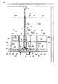
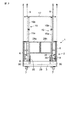
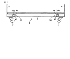
図1にはゴンドラ装置1の側面図を、図2には同じく正面図を示してある。ゴンドラ装置1はゴンドラ本体2を備え、このゴンドラ本体2は床枠部3を有し、この床枠部3の両側部の上面に互いに対向するように断面L状の鋼材4が取り付けられ、これら鋼材4の起立側面にその上方に立ち上がるように、複数の桟材5で構成された手摺枠6が取り付けられている。そして、床枠部3の下面の四隅部分に、ゴンドラ装置1を走行させるためのキャスター7が取り付けられている。   FIG. 1 shows a side view of the gondola apparatus 1, and FIG. The gondola apparatus 1 includes a gondola body 2, which has a floor frame portion 3, and steel materials 4 having an L-shaped cross section are attached to the upper surfaces of both side portions of the floor frame portion 3. A handrail frame 6 composed of a plurality of crosspieces 5 is attached to a standing side surface of the steel material 4 so as to rise upward. Then, casters 7 for running the gondola device 1 are attached to the four corners of the lower surface of the floor frame portion 3.

ゴンドラ本体2の内側の両側下部には電動ウインチ8が取り付けられ、これら電動ウインチ8は駆動ロープ9を備え、ゴンドラ装置1の使用時にこれら駆動ロープ9が昇降路10の天井部に設けられたフック11に連結される。そして、電動ウインチ8の駆動で駆動ロープ9が巻き取られることでゴンドラ装置1が昇降路10内に吊下げられ、またその電動ウインチ8の駆動を制御することでゴンドラ装置1を上下に移動させることができるようになっている。   Electric winches 8 are attached to the lower portions on both sides inside the gondola main body 2, and these electric winches 8 are provided with drive ropes 9, and these drive ropes 9 are hooks provided on the ceiling of the hoistway 10 when the gondola device 1 is used. 11. The gondola device 1 is suspended in the hoistway 10 by winding the drive rope 9 by driving the electric winch 8, and the gondola device 1 is moved up and down by controlling the drive of the electric winch 8. Be able to.

ゴンドラ本体2の内側の両側には伸縮支柱15が取り付けられている。これら伸縮支柱15はゴンドラ本体2に対して上下に伸縮可能な第1の支柱材15aと、この第1の支柱材15aに対して上下に伸縮可能な第2の支柱材15bとで構成されている。そしてこれら伸縮支柱15における第2の支柱材15bの上端部間に保護天井17が水平に架設されている。この保護天井17は、前記支柱材15bに固定された主天井18と、この主天井18に対してゴンドラ本体2の前後方向に水平に伸縮可能に取り付けられた二つの可動天井19a,19bとで構成されている。   Extendable struts 15 are attached to both sides inside the gondola body 2. These telescopic struts 15 are composed of a first strut member 15a that can be vertically expanded and contracted with respect to the gondola body 2, and a second strut member 15b that can be vertically expanded and contracted with respect to the first strut member 15a. Yes. A protective ceiling 17 is installed horizontally between the upper ends of the second support members 15b in the telescopic support columns 15. The protective ceiling 17 includes a main ceiling 18 fixed to the column member 15b, and two movable ceilings 19a and 19b attached to the main ceiling 18 so as to be horizontally extendable in the front-rear direction of the gondola body 2. It is configured.

ゴンドラ本体2の前部には前側手摺枠部22が設けられている。図4にはゴンドラ本体2と前側手摺枠部22との結合構造を示してある。前側手摺枠部22は、下部両側に断面L状の鋼材23を備え、これら鋼材23は互い対向するとともに、桟材21を介して互いに結合されている。そして各鋼材23の起立側面に、図1に示すようにその上方に立ち上がる手摺枠25が取り付けられている。手摺枠25は複数の桟材24を組み合わせて構成されている。   A front handrail frame portion 22 is provided at the front portion of the gondola body 2. FIG. 4 shows a coupling structure between the gondola body 2 and the front handrail frame portion 22. The front handrail frame portion 22 includes steel materials 23 having a L-shaped cross section on both sides of the lower portion, and these steel materials 23 face each other and are coupled to each other via a crosspiece 21. And the handrail frame 25 which stands up as shown in FIG. 1 is attached to the standing side surface of each steel material 23. The handrail frame 25 is configured by combining a plurality of crosspieces 24.

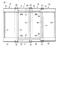
前側手摺枠部22の各鋼材23はゴンドラ本体2の鋼材4の内側に摺動自在に重ね合わされ、その鋼材4に対して摺動することにより前側手摺枠部22がゴンドラ本体2の前後方向に伸縮するようになっている。図1及び図4には前側手摺枠部22が伸長した状態を示してあり、この状態は前側手摺枠部22の鋼材23とゴンドラ本体2の鋼材4との重なり部をボルトなどの締結部材26で互いに締結することにより固定される。図3には前側手摺枠部22をゴンドラ本体2内に収納して縮小した状態を示してある。   Each steel material 23 of the front handrail frame portion 22 is slidably superimposed on the inside of the steel material 4 of the gondola main body 2, and the front handrail frame portion 22 is moved in the front-rear direction of the gondola main body 2 by sliding with respect to the steel material 4. It is designed to expand and contract. 1 and 4 show a state in which the front handrail frame portion 22 is extended. In this state, an overlapping portion of the steel material 23 of the front handrail frame portion 22 and the steel material 4 of the gondola main body 2 is a fastening member 26 such as a bolt. It is fixed by fastening with each other. FIG. 3 shows a state in which the front handrail frame portion 22 is housed in the gondola body 2 and reduced.

前側手摺枠部22の内側には図1に示すように前記電動ウインチ8を運転操作するための制御盤27が着脱可能に取り付けられ、また図2に示すように前側手摺枠部22の前面の開放部にはその開閉用の開閉枠28a,28bが設けられている。   A control panel 27 for operating the electric winch 8 is detachably attached to the inside of the front handrail frame portion 22 as shown in FIG. 1, and the front panel of the front handrail frame portion 22 is attached as shown in FIG. Opening and closing frames 28a and 28b are provided at the opening portion.

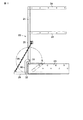
さらに、前側手摺枠部22の前面下部には跳ね出し足場29が設けられている。この跳ね出し足場29は、その左右側の両端部がリンクレバー30を介して前側手摺枠部22の前部に連結されている。図5には跳ね出し足場29の取り付け部の構造を拡大して示してあり、リンクレバー30はほぼ逆L字状をなし、その一端部がヒンジピン31を介して前側手摺枠部22の桟材24に回動自在に枢着され、他端部がヒンジピン32を介して跳ね出し足場29の端部に回動自在に枢着されている。   Further, a jumping scaffold 29 is provided at the lower front part of the front handrail frame portion 22. The right and left ends of the jumping scaffold 29 are connected to the front part of the front handrail frame part 22 via the link lever 30. FIG. 5 is an enlarged view of the structure of the attachment part of the jumping scaffold 29, the link lever 30 has a substantially inverted L shape, and one end of the link lever 30 is connected to the front handrail frame part 22 via the hinge pin 31. The other end portion is pivotally attached to the end portion of the scaffold 29 via the hinge pin 32 so as to be rotatable.

跳ね出し足場29の前部と前側手摺枠部22の桟材24との間には支持用のチェーン35が掛け渡され、このチェーン35と前記リンクレバー30とで支持されて跳ね出し足場29の後端面が前側手摺枠部22の前面下部に当接することにより跳ね出し足場29がほぼ水平に保持され、この状態から跳ね出し足場29をヒンジピン31を中心に上方に引き上げて前側手摺枠部22の内側に移動させることにより跳ね出し足場29を前側手摺枠部22の内側下部に収納することができるようになっている。そして収納した跳ね出し足場29をその収納時の逆順の操作で前側手摺枠部22の前部に水平に突出する状態に配置させることができるようになっている。   A support chain 35 is spanned between the front part of the jumping scaffold 29 and the crosspiece 24 of the front handrail frame part 22, and is supported by the chain 35 and the link lever 30 so as to support the jumping scaffold 29. As the rear end surface comes into contact with the lower front portion of the front handrail frame portion 22, the jumping scaffold 29 is held almost horizontally. From this state, the jumping scaffold 29 is lifted upward about the hinge pin 31 and the front handrail frame portion 22 The jumping scaffold 29 can be stored in the lower part on the inner side of the front handrail frame portion 22 by being moved inward. Then, the stored jumping scaffold 29 can be arranged in a state of projecting horizontally from the front part of the front handrail frame part 22 by an operation in the reverse order at the time of storage.

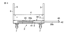
ゴンドラ本体2の底部には、図5に示すようにその左右側に離れて二つの伸縮可能な支え装置38が設けられている。これら支え装置38は、ゴンドラ本体2の底部にその前後方向に沿って固定された断面角形の外パイプ39aと、この外パイプ39a内に摺動自在に挿入された断面角形の内パイプ39bとで構成されている。   As shown in FIG. 5, two extendable support devices 38 are provided on the bottom of the gondola body 2 so as to be separated from each other on the left and right sides. These support devices 38 include an outer pipe 39a having a square section fixed to the bottom of the gondola body 2 along the front-rear direction, and an inner pipe 39b having a square section slidably inserted into the outer pipe 39a. It is configured.

外パイプ39aの一側面には、図6に示すようにその長手方向に沿ってスリット状の長孔40が形成され、この長孔40を通して外パイプ39aの外側から内パイプ39bの端部側面にボルトなどからなるストッパーピン41が取り付けられている。したがって内パイプ39bは長孔40の長さ分だけゴンドラ本体2の後方側に伸長して突出することができ、ストッパーピン41が長孔40の端部に当接することにより内パイプ39bの抜け落ちが防止される。   As shown in FIG. 6, a slit-like long hole 40 is formed on one side surface of the outer pipe 39a along the longitudinal direction thereof, and the outer side of the outer pipe 39a passes from the outer side of the outer pipe 39a to the end side surface of the inner pipe 39b. A stopper pin 41 made of a bolt or the like is attached. Therefore, the inner pipe 39b can extend and protrude toward the rear side of the gondola body 2 by the length of the long hole 40, and the stopper pin 41 abuts on the end of the long hole 40, so that the inner pipe 39b is not dropped. Is prevented.

内パイプ39bの突出先端側の端面には端板42が取り付けられ、この端板42の一部は図7に示すように内パイプ39bの側方に突出し、その突出部に透孔44が形成されている。内パイプ39bをゴンドラ本体2の内側に向けて押し込んで縮小させたときには、前記端板42がゴンドラ本体2の後端面に当接する。そして、前記端板42の透孔44を通してゴンドラ本体2の後端面にボルトを螺挿して締め付けることにより内パイプ39bをゴンドラ本体2に固定してその飛び出しを防止することができるようになっている。また、内パイプ39bの突出先端側の上面には支持駒46が取り付けられている。   An end plate 42 is attached to the end face of the inner pipe 39b on the protruding tip side, and a part of the end plate 42 protrudes to the side of the inner pipe 39b as shown in FIG. 7, and a through hole 44 is formed in the protruding portion. Has been. When the inner pipe 39b is pushed in toward the inside of the gondola body 2 and reduced, the end plate 42 comes into contact with the rear end surface of the gondola body 2. The inner pipe 39b can be fixed to the gondola body 2 and prevented from popping out by screwing a bolt into the rear end surface of the gondola body 2 through the through hole 44 of the end plate 42 and tightening it. . A support piece 46 is attached to the upper surface of the projecting tip side of the inner pipe 39b.

図1に示すように、ゴンドラ本体2の後部内側には継ぎ足し手摺枠部48が設けられている。この継ぎ足し手摺枠部48は、図4に示すように下部両側に互いに対向する断面L状の鋼材50を備え、これら鋼材50が桟材51を介して互いに結合されている。そして各鋼材50の側面に、図1に示すようにその上方に立ち上がる手摺枠52が取り付けられている。手摺枠52は複数の桟材54を組み合わせて構成されている。   As shown in FIG. 1, an additional handrail frame 48 is provided inside the rear part of the gondola body 2. As shown in FIG. 4, the additional handrail frame portion 48 includes steel materials 50 having L-shaped cross sections facing each other on both sides of the lower portion, and these steel materials 50 are coupled to each other via a crosspiece 51. As shown in FIG. 1, a handrail frame 52 that rises upward is attached to the side surface of each steel material 50. The handrail frame 52 is configured by combining a plurality of crosspieces 54.

継ぎ足し手摺枠部48の各鋼材50はゴンドラ本体2の鋼材4の内側に摺動自在に重ね合わされ、その鋼材4に対して摺動することにより継ぎ足し手摺枠部48がゴンドラ本体2の前後方向に伸縮するようになっている。   Each steel material 50 of the additional handrail frame portion 48 is slidably superimposed on the inner side of the steel material 4 of the gondola main body 2, and the additional handrail frame portion 48 is moved in the front-rear direction of the gondola main body 2 by sliding with respect to the steel material 4. It is designed to expand and contract.

図1及び図4は継ぎ足し手摺枠部48を伸長させた状態を示してあり、この状態は継ぎ足し手摺枠部48の鋼材50とゴンドラ本体2の鋼材4との重なり部をボルトなどの締結部材53で締結することにより固定される。また、この伸長状態のもとでは、前記各支え装置38の内パイプ39bが伸長され、これら内パイプ39bにより継ぎ足し手摺枠部48が支持される。すなわち、伸長した内パイプ39bの先端の支持駒46が継ぎ足し手摺枠部48の鋼材50の下面に接触して継ぎ足し手摺枠部48が下から支持される。   1 and 4 show a state in which the extension handrail frame portion 48 is extended. In this state, the overlapping portion of the steel material 50 of the extension handrail frame portion 48 and the steel material 4 of the gondola body 2 is connected to a fastening member 53 such as a bolt. It is fixed by fastening with. Further, under this extended state, the inner pipe 39b of each support device 38 is extended, and the additional handrail frame portion 48 is supported by the inner pipe 39b. That is, the support piece 46 at the tip of the extended inner pipe 39b is added to the lower surface of the steel material 50 of the handrail frame portion 48, and the added handrail frame portion 48 is supported from below.

継ぎ足し手摺枠部48の後部にはその後方側に延びるように後側手摺枠部55が取り付けられている。この後側手摺枠部55は、下部両側に互いに対向する断面L状の鋼材57を備え、これら鋼材57は桟材58を介して互いに結合されている。そして各鋼材57の側面に、図1に示すようにその上方に立ち上がる手摺枠60が取り付けられている。手摺枠60は複数の桟材62を組み合わせて構成されている。   A rear handrail frame portion 55 is attached to the rear portion of the added handrail frame portion 48 so as to extend rearward thereof. The rear handrail frame portion 55 includes steel members 57 having an L-shaped cross section facing each other on both sides of the lower portion, and these steel members 57 are coupled to each other via a crosspiece 58. And the handrail frame 60 which stands up as shown in FIG. 1 is attached to the side surface of each steel material 57. The handrail frame 60 is configured by combining a plurality of crosspieces 62.

後側手摺枠部55は各鋼材57の一端側の端部が継ぎ足し手摺枠部48の鋼材50の内側に重ね合わされ、その重なり部をボルトなどの締結部材61で締結することにより継ぎ足し手摺枠部48に着脱可能に取り付けられている。   The rear handrail frame portion 55 has an end portion on one end side of each steel material 57 added and superimposed on the inner side of the steel material 50 of the handrail frame portion 48, and the overlapped portion is fastened by a fastening member 61 such as a bolt to add the handrail frame portion. 48 is detachably attached.

ゴンドラ本体2に対して前側手摺枠部22、継ぎ足し手摺枠部48が伸長され、その継ぎ足し手摺枠部48に後側手摺枠部55が取り付けられたときには、前側手摺枠部22の鋼材23間、継ぎ足し手摺枠部48の鋼材50間、後側手摺枠部55の鋼材57間に図1に示すようにそれぞれ足場板63が敷き詰められる。   When the front handrail frame portion 22 and the additional handrail frame portion 48 are extended with respect to the gondola body 2 and the rear handrail frame portion 55 is attached to the additional handrail frame portion 48, the steel material 23 between the front handrail frame portion 22, As shown in FIG. 1, scaffold plates 63 are spread between the steel members 50 of the additional handrail frame portion 48 and between the steel members 57 of the rear handrail frame portion 55.

このゴンドラ装置1を昇降路10内に搬入するときには、前記各足場板63を取り外し、前記継ぎ足し手摺枠部48から後側手摺枠部55を取り外し、かつ伸縮支柱15、前側手摺枠部22、継ぎ足し手摺枠部48、支え装置38及び跳ね出し足場29をそれぞれゴンドラ本体2内に収納して縮小し、この縮小したコンパクトな状態でゴンドラ装置1を昇降路10内に搬入し、昇降路10のピット部に配置する。この際、前記各足場板63及び後側手摺枠部55はゴンドラ本体2内に積み込んでおく。   When the gondola device 1 is carried into the hoistway 10, each scaffold plate 63 is removed, the rear handrail frame portion 55 is removed from the additional handrail frame portion 48, and the telescopic strut 15, the front handrail frame portion 22, and the additional foot are added. The handrail frame 48, the support device 38, and the jumping scaffold 29 are respectively accommodated in the gondola body 2 and reduced, and the gondola device 1 is carried into the hoistway 10 in this reduced and compact state, and the pit of the hoistway 10 is obtained. Placed in the section. At this time, the respective scaffold plates 63 and the rear handrail frame portion 55 are loaded in the gondola body 2.

この後、伸縮支柱15を伸長し、その上端部の保護天井17の可動天井19a,19bを伸長して拡張し、またゴンドラ本体2から前側手摺枠部22及び継ぎ足し手摺枠部48を伸長し、締結部材26,53でその伸長状態を固定し、さらに支え装置38の内パイプ39bを伸長して継ぎ足し手摺枠部48をその下から支持する。そして、継ぎ足し手摺枠部48に後側手摺枠部55を取り付け、締結部材61で締結し、前側手摺枠部22、継ぎ足し手摺枠部48及び後側手摺枠部55の各底部に足場板63を敷き詰め、また跳ね出し足場29をゴンドラ本体2の前部側に回動して水平に突出させる。   Thereafter, the telescopic support column 15 is extended, the movable ceilings 19a and 19b of the protective ceiling 17 at the upper end thereof are extended and extended, and the front handrail frame portion 22 and the additional handrail frame portion 48 are extended from the gondola body 2. The extended state is fixed by the fastening members 26 and 53, and the inner pipe 39b of the support device 38 is further extended and added to support the handrail frame portion 48 from below. Then, the rear handrail frame portion 55 is attached to the additional handrail frame portion 48 and fastened by the fastening member 61, and the scaffolding plate 63 is attached to each bottom portion of the front handrail frame portion 22, the additional handrail frame portion 48, and the rear handrail frame portion 55. The spread scaffold 29 is turned to the front side of the gondola body 2 so as to protrude horizontally.

次に、電動ウインチ8から駆動ロープ9を引き出し、その先端部を昇降路10の天井部のフック11に掛止める。そして、ゴンドラ装置1内に作業員が乗り込む。ゴンドラ装置1内に作業員が乗り込む際には、前側手摺枠部22の前部に突出している跳ね出し足場29に足を掛け、開閉枠28a,28bを開いて乗り込む。また、ゴンドラ装置1から降りるときにも前記跳ね出し足場29に足を掛けて降りる。これによりゴンドラ装置1に対する乗り降りを容易にかつ安全に行なえる。   Next, the drive rope 9 is pulled out from the electric winch 8, and its tip is hooked to the hook 11 on the ceiling of the hoistway 10. Then, an operator gets into the gondola device 1. When an operator gets into the gondola apparatus 1, he gets on the jumping scaffold 29 protruding from the front part of the front handrail frame part 22 and gets in with the opening and closing frames 28 a and 28 b opened. In addition, when getting off the gondola device 1, the user jumps on the jumping scaffold 29 and gets down. This makes it possible to easily and safely get on and off the gondola device 1.

ゴンドラ装置1に作業員が乗り込んだ後には、制御盤27を操作し、電動ウインチ8を駆動してゴンドラ装置1を所望の位置に吊り上げ、また上下に移動させながらエレベータ用品としての例えばガイドレールを昇降路10の壁面に据え付けたり、昇降路10の出入口に三方枠を据え付けたりする。   After an operator gets into the gondola device 1, the control panel 27 is operated to drive the electric winch 8 to lift the gondola device 1 to a desired position and to move up and down, for example, a guide rail as an elevator article. It is installed on the wall surface of the hoistway 10, or a three-way frame is installed at the entrance of the hoistway 10.

このゴンドラ装置1においては、ゴンドラ本体2の前方側に前側手摺枠部22が伸長し、後方側に継ぎ足し手摺枠部48及び後側手摺枠部55が伸長して作業域が広がり、その作業域の周囲が手摺枠6,25,52,60で囲まれており、このためゴンドラ装置1内に乗り込んだ作業員が昇降路10の内壁面の近くにまで移動して容易に能率よくかつ安全に昇降路10の内壁面などにエレベータ用品を据え付けることができる。   In this gondola apparatus 1, the front handrail frame portion 22 extends to the front side of the gondola body 2, and the handrail frame portion 48 and the rear handrail frame portion 55 extend to the rear side to expand the work area. Is surrounded by handrail frames 6, 25, 52, 60, so that an operator who gets into the gondola device 1 moves to the vicinity of the inner wall surface of the hoistway 10 and is easily and efficiently and safely. An elevator article can be installed on the inner wall surface of the hoistway 10 or the like.

特に、ゴンドラ本体2の後方側には継ぎ足し手摺枠部48と後側手摺枠部55とが二段式に伸長しており、このため奥行寸法の大きな昇降路10の場合であっても、そのゴンドラ装置1が昇降路10の奥行側の壁面に接近し、このため作業員が大きく身を乗り出すような不自然で危険な体勢をとることなく、容易にその壁面にエレベータ用品を据え付けることができる。   In particular, an additional handrail frame portion 48 and a rear handrail frame portion 55 extend in a two-stage manner on the rear side of the gondola body 2, so even in the case of the hoistway 10 having a large depth dimension, The gondola device 1 approaches the wall surface on the depth side of the hoistway 10, and therefore, elevator equipment can be easily installed on the wall surface without taking an unnatural and dangerous posture in which a worker leans forward. .

また、ゴンドラ本体2の前部側に伸長した前側手摺枠部22の前部には跳ね出し足場29がその前方に水平に突出するように配置されており、このためその跳ね出し足場29の分だけゴンドラ装置1が昇降路10の前側に接近し、このため作業の途中などに昇降路10の前側の出入口からゴンドラ装置1に対して乗り降りする際に、その跳ね出し足場29に足を掛けて容易に能率よくかつ安全に乗り降りすることができる。   Further, a jumping scaffold 29 is arranged in front of the front handrail frame portion 22 extended to the front side of the gondola body 2 so as to protrude horizontally in front of the front handrail frame part 22. Only when the gondola device 1 approaches the front side of the hoistway 10, and when getting on and off the gondola device 1 from the front entrance of the hoistway 10 during the work, etc. You can easily get on and off efficiently and safely.

継ぎ足し手摺枠部48は支え装置38により下から支持されて補強されており、したがってその伸長状態を安定して保持することができる。また、跳ね出し足場29はその先端部と前側手摺枠部22とに渡って掛け渡されたチェーン35で支持されて補強されており、したがってその水平突出状態を安定して保持することができる。   The extension handrail frame portion 48 is supported and reinforced by the support device 38 from below, and therefore, the extended state can be stably held. Further, the jumping scaffold 29 is supported and reinforced by a chain 35 that spans between the front end portion and the front handrail frame portion 22, so that the horizontal protruding state can be stably maintained.

エレベータ用品の据え付け作業が終了した後には、ゴンドラ装置1を昇降路10のピット部に降し、電動ウインチ8の駆動ロープ9を昇降路10の天井部のフック11から取り外す。そしてゴンドラ装置1の内側の各足場板63を取り外し、また後側手摺枠部55を継ぎ足し手摺枠部48から取り外す。さらに、前側手摺枠部22及び継ぎ足し手摺枠部48をそれぞれゴンドラ本体2内に収納して縮小し、跳ね出し足場29を回動して前側手摺枠部22の内側に収納し、伸縮支柱15を縮小してゴンドラ本体2内に収納し、保護天井17の可動天井19a,19bを主天井18内に収納して縮小する。なお、ゴンドラ装置1から取り外した前記各足場板63及び継ぎ足し手摺枠部48から取り外した前記後側手摺枠部55はゴンドラ本体2内に積み込む。   After the elevator work is completed, the gondola device 1 is lowered to the pit portion of the hoistway 10, and the drive rope 9 of the electric winch 8 is removed from the hook 11 on the ceiling portion of the hoistway 10. Then, each scaffold plate 63 inside the gondola device 1 is removed, and the rear handrail frame portion 55 is added and removed from the handrail frame portion 48. Further, the front handrail frame portion 22 and the additional handrail frame portion 48 are respectively accommodated in the gondola body 2 and reduced, the jumping scaffold 29 is rotated and accommodated inside the front handrail frame portion 22, and the telescopic strut 15 is installed. The movable ceiling 19a, 19b of the protective ceiling 17 is accommodated in the main ceiling 18 and reduced. The scaffold plates 63 removed from the gondola device 1 and the rear handrail frame portion 55 removed from the additional handrail frame portion 48 are loaded into the gondola body 2.

これによりゴンドラ装置1の全体がコンパクトな小型の状態に縮小する。そしてこの状態でゴンドラ装置1を昇降路10に通じる建屋の出入口を通して昇降路10から搬出する。   As a result, the entire gondola device 1 is reduced to a compact and compact state. In this state, the gondola device 1 is carried out of the hoistway 10 through the entrance of the building that leads to the hoistway 10.

この際、ゴンドラ装置1の全体は小型のコンパクトな状態に縮小されており、このため前記出入口の内周部に三方枠が取り付けられ、その開口幅が狭まっていてもゴンドラ装置1を容易に搬出することができる。 At this time, the entire gondola device 1 has been reduced to a compact and compact state. Therefore, a three-sided frame is attached to the inner peripheral portion of the entrance, and the gondola device 1 can be easily carried out even if the opening width is narrow. can do.

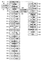
建屋の昇降路10にエレベータを設置するときの着工の開始から引渡しまでの全体の作業工程の流れを図9に示してある。図9のステップ3に示すように、昇降路10内には揚重装置が設置され、この揚重装置を用いてゴンドラ装置1の搬入や吊下げなどの作業が行なわれる。そしてステップ31で示す昇降路10内でのかごの組み立てが行なわれる前にゴンドラ装置1の縮小や搬出の作業が行なわれる。   FIG. 9 shows the flow of the entire work process from the start of construction to delivery when the elevator is installed in the hoistway 10 of the building. As shown in step 3 of FIG. 9, a lifting device is installed in the hoistway 10, and operations such as loading and hanging of the gondola device 1 are performed using this lifting device. Then, before the car is assembled in the hoistway 10 shown in step 31, the operation of reducing or carrying out the gondola device 1 is performed.

この発明の一実施形態に係るゴンドラ装置の拡張時の状態を示す側面図。The side view which shows the state at the time of expansion of the gondola apparatus which concerns on one Embodiment of this invention. ゴンドラ装置を前側から見た正面図。The front view which looked at the gondola apparatus from the front side. ゴンドラ装置の縮小時の状態を示す側面図。The side view which shows the state at the time of reduction of a gondola apparatus. ゴンドラ装置のゴンドラ本体に対する前側手摺枠部、継ぎ足し手摺枠部、後側手摺枠部の結合構造を示す平面図。The top view which shows the coupling | bonding structure of the front side handrail frame part with respect to the gondola main body of a gondola apparatus, an additional handrail frame part, and a rear handrail frame part. ゴンドラ装置の跳ね出し足場の支持構造を示す側面図。The side view which shows the support structure of the jumping scaffold of a gondola apparatus. ゴンドラ装置の支え装置の構造を示す側面図。The side view which shows the structure of the support apparatus of a gondola apparatus. ゴンドラ装置の支え装置の構造を示す正面図。The front view which shows the structure of the support apparatus of a gondola apparatus. エレベータを昇降路に設置する際の着工開始からその完了までの作業工程を順に示すフローチャート。The flowchart which shows the work process from the start of construction at the time of installing an elevator in a hoistway to the completion thereof in order.

符号の説明Explanation of symbols

1…ゴンドラ装置
2…ゴンドラ本体
3…床枠部
6…手摺枠
8…電動ウインチ
9…駆動ロープ
10…昇降路
15…伸縮支柱
17…保護天井
22…前側手摺枠部
23…鋼材
25…手摺枠
26…締結部材
27…制御盤
29…跳ね出し足場
35…チェーン
38…支え装置
48…継ぎ足し手摺枠部
52…手摺枠
53…締結部材
55…後側手摺枠部
60…手摺枠
61…締結部材
63…足場板
DESCRIPTION OF SYMBOLS 1 ... Gondola apparatus 2 ... Gondola main body 3 ... Floor frame part 6 ... Handrail frame 8 ... Electric winch 9 ... Drive rope 10 ... Hoistway 15 ... Telescopic support 17 ... Protective ceiling 22 ... Front handrail frame part 23 ... Steel material 25 ... Handrail frame DESCRIPTION OF SYMBOLS 26 ... Fastening member 27 ... Control board 29 ... Jumping scaffold 35 ... Chain 38 ... Supporting device 48 ... Additional handrail frame part 52 ... Handrail frame 53 ... Fastening member 55 ... Rear handrail frame part 60 ... Handrail frame 61 ... Fastening member 63 ... scaffolding board

Claims (4)

電動ウインチを有する吊下げ昇降機構を備え、その吊下げ昇降機構によりエレベータの昇降路内に吊下げられ、かつ前記電動ウインチによる駆動で前記昇降路内を上下に移動して昇降路内にエレベータ用品を据え付けるために使用されるゴンドラ装置であって、
前記吊下げ昇降機構により前記昇降路内に吊下げられるゴンドラ本体と、このゴンドラ本体の前部にその前方に向く水平方向に伸縮可能に設けられた前側手摺枠部と、前記ゴンドラ本体の後部にその後方に向く水平方向に伸縮可能に設けられた継ぎ足し手摺枠部と、この継ぎ足し手摺枠部の後部に脱着可能に取り付けられて該継ぎ足し手摺枠部の後方側に延びる後側手摺枠部とを備えることを特徴とするエレベータ用品据え付け用ゴンドラ装置。
A lifting / lowering mechanism having an electric winch is provided, which is suspended in an elevator hoistway by the lifting / lowering mechanism, and is moved up and down in the hoistway by driving by the electric winch to be an elevator article in the hoistway. A gondola device used for installing
A gondola main body suspended in the hoistway by the suspension elevating mechanism, a front handrail frame portion provided in the front portion of the gondola main body so as to be extendable in the horizontal direction, and a rear portion of the gondola main body. An additional handrail frame portion that is provided to extend horizontally in the rearward direction, and a rear handrail frame portion that is detachably attached to the rear portion of the additional handrail frame portion and extends to the rear side of the additional handrail frame portion. A gondola device for installing elevator equipment, comprising:
前記ゴンドラ本体の底部には、該ゴンドラ本体の後方に向く水平方向に伸縮可能な支え装置が設けられ、前記継ぎ足し手摺枠部を前記ゴンドラ本体からその後方側に伸長させたときに、前記支え装置を前記ゴンドラ本体からその後方側に伸長させて前記継ぎ足し手摺枠部を下から支えて支持することが可能なことを特徴とする請求項1に記載のエレベータ用品据え付け用ゴンドラ装置。   At the bottom of the gondola body is provided a support device that can be expanded and contracted in the horizontal direction toward the rear of the gondola body, and when the additional handrail frame is extended from the gondola body to the rear side, the support device The elevator gondola device according to claim 1, characterized in that it can be extended from the gondola main body to the rear side to support and support the handrail frame portion from below. 前記前側手摺枠部の前部には、ゴンドラ装置への乗り降りの際に使用する跳ね出し足場が前記前側手摺枠部の内部に対して収納可能に設けられていることを特徴とする請求項1又は2に記載のエレベータ用品据え付け用ゴンドラ装置。   2. A jumping scaffold used for getting on and off the gondola device is provided at a front portion of the front handrail frame portion so as to be housed in the front handrail frame portion. Or the gondola apparatus for elevator article installation of 2. 請求項1乃至3のいずれかに記載のゴンドラ装置を前記昇降路内に搬入し、前記昇降路内において前記前側手摺枠部及び継ぎ足し手摺枠部を伸長し、かつその継ぎ足し手摺枠部に後側手摺枠部を取り付けてゴンドラ装置を拡張し、この状態でゴンドラ装置を前記吊下げ機構により前記昇降路内に吊下げ、かつゴンドラ装置内に作業員が乗り込み、前記電動ウインチを制御してゴンドラ装置を上下に移動させながら前記昇降路内にエレベータ用品を据え付けることを特徴とするエレベータ用品据え付け作業方法。   The gondola device according to claim 1 is carried into the hoistway, the front handrail frame portion and the additional handrail frame portion are extended in the hoistway, and the rear side of the additional handrail frame portion is rearward. A gondola device is expanded by attaching a handrail frame portion. In this state, the gondola device is suspended in the hoistway by the suspension mechanism, and an operator enters the gondola device to control the electric winch to control the gondola device. An elevator article installation work method, wherein an elevator article is installed in the hoistway while moving the elevator up and down.
JP2006122452A 2006-04-26 2006-04-26 Elevator equipment gondola device and elevator equipment installation work method Active JP5132080B2 (en)

Priority Applications (1)

Application Number Priority Date Filing Date Title
JP2006122452A JP5132080B2 (en) 2006-04-26 2006-04-26 Elevator equipment gondola device and elevator equipment installation work method

Applications Claiming Priority (1)

Application Number Priority Date Filing Date Title
JP2006122452A JP5132080B2 (en) 2006-04-26 2006-04-26 Elevator equipment gondola device and elevator equipment installation work method

Publications (2)

Publication Number Publication Date
JP2007290835A true JP2007290835A (en) 2007-11-08
JP5132080B2 JP5132080B2 (en) 2013-01-30

Family

ID=38761850

Family Applications (1)

Application Number Title Priority Date Filing Date
JP2006122452A Active JP5132080B2 (en) 2006-04-26 2006-04-26 Elevator equipment gondola device and elevator equipment installation work method

Country Status (1)

Country Link
JP (1) JP5132080B2 (en)

Cited By (2)

* Cited by examiner, † Cited by third party
Publication number Priority date Publication date Assignee Title
KR101280916B1 (en) * 2008-10-07 2013-07-02 김송강 The construction workbench for an elevator infrastructure establishment
JP7380819B1 (en) 2022-12-06 2023-11-15 フジテック株式会社 Elevator work car device

Citations (9)

* Cited by examiner, † Cited by third party
Publication number Priority date Publication date Assignee Title
JPS51112050A (en) * 1975-03-26 1976-10-04 Toshiba Corp Gondola structure for elevator installation
JPS5847783A (en) * 1981-09-14 1983-03-19 三菱電機株式会社 Device for installing elevator
JPS59163282A (en) * 1983-03-09 1984-09-14 株式会社日立ビルシステムサ−ビス Work floor device for installing elevator
JPH02186063A (en) * 1989-01-13 1990-07-20 Hitachi Ltd Scaffolding device for installing elevator
JPH07117994A (en) * 1993-10-29 1995-05-09 Nippon Sharyo Seizo Kaisha Ltd Vehicle for high lift work
JPH08231200A (en) * 1994-12-27 1996-09-10 Nippon Sharyo Seizo Kaisha Ltd Vehicle for high lift work
JPH11165965A (en) * 1997-12-02 1999-06-22 Fujitec Co Ltd Work floor device for installing elevator
JP2000177952A (en) * 1998-12-17 2000-06-27 Hitachi Building Systems Co Ltd Work floor device for elevator installation
JP2005023699A (en) * 2003-07-04 2005-01-27 Ohbayashi Corp Gondola and gondola moving method

Patent Citations (9)

* Cited by examiner, † Cited by third party
Publication number Priority date Publication date Assignee Title
JPS51112050A (en) * 1975-03-26 1976-10-04 Toshiba Corp Gondola structure for elevator installation
JPS5847783A (en) * 1981-09-14 1983-03-19 三菱電機株式会社 Device for installing elevator
JPS59163282A (en) * 1983-03-09 1984-09-14 株式会社日立ビルシステムサ−ビス Work floor device for installing elevator
JPH02186063A (en) * 1989-01-13 1990-07-20 Hitachi Ltd Scaffolding device for installing elevator
JPH07117994A (en) * 1993-10-29 1995-05-09 Nippon Sharyo Seizo Kaisha Ltd Vehicle for high lift work
JPH08231200A (en) * 1994-12-27 1996-09-10 Nippon Sharyo Seizo Kaisha Ltd Vehicle for high lift work
JPH11165965A (en) * 1997-12-02 1999-06-22 Fujitec Co Ltd Work floor device for installing elevator
JP2000177952A (en) * 1998-12-17 2000-06-27 Hitachi Building Systems Co Ltd Work floor device for elevator installation
JP2005023699A (en) * 2003-07-04 2005-01-27 Ohbayashi Corp Gondola and gondola moving method

Cited By (2)

* Cited by examiner, † Cited by third party
Publication number Priority date Publication date Assignee Title
KR101280916B1 (en) * 2008-10-07 2013-07-02 김송강 The construction workbench for an elevator infrastructure establishment
JP7380819B1 (en) 2022-12-06 2023-11-15 フジテック株式会社 Elevator work car device

Also Published As

Publication number Publication date
JP5132080B2 (en) 2013-01-30

Similar Documents

Publication Publication Date Title
JP5264581B2 (en) Self-climbing lift
JP4796195B1 (en) Work scaffold equipment
JP2009051574A (en) Scaffolding for construction work of elevator, and scaffolding installing method using the same
JP5039374B2 (en) Working device in mechanical parking device and its working method
US11731857B2 (en) Movable machine room, elevator arrangement and method for constructing elevator
CA3081409A1 (en) Hoist platform system for multi-floor building construction
KR20110137864A (en) Lift for construction work
JP4140036B2 (en) Trolley-type work scaffolding
JP2006299559A (en) Self climbing scaffold and self climbing method by use of it
JP5132080B2 (en) Elevator equipment gondola device and elevator equipment installation work method
JP4921810B2 (en) Elevator installation apparatus and installation method using the same
JP2008222382A (en) Method for moving lifting device for installation
KR20170129422A (en) Multi-type lifting scaffold
JP4898255B2 (en) Mobile scaffolding and powerless descent device
JP4316514B2 (en) Working device in mechanical parking device and its working method
JP4520454B2 (en) Cargo elevator for building components
JP2000145129A (en) Staging provided with load lifter
KR200430674Y1 (en) High place working gondola in building
JP4952014B2 (en) Building demolition method and maintenance method, curing scaffold descent device
JPH0270688A (en) Temporary crane device for construction work
JP2008214062A (en) Lifting device and structural material mounting method
KR101800622B1 (en) Multi-type lifting scaffold
KR100925864B1 (en) Working platform for high place working gondola in building
JP2004143677A (en) Carrying in/out device of construction machine and material
JP4245315B2 (en) Moving scaffold for elevator installation and elevator installation method

Legal Events

Date Code Title Description
A621 Written request for application examination

Free format text: JAPANESE INTERMEDIATE CODE: A621

Effective date: 20090331

A131 Notification of reasons for refusal

Free format text: JAPANESE INTERMEDIATE CODE: A131

Effective date: 20111115

A977 Report on retrieval

Free format text: JAPANESE INTERMEDIATE CODE: A971007

Effective date: 20111117

A521 Written amendment

Free format text: JAPANESE INTERMEDIATE CODE: A523

Effective date: 20120110

RD04 Notification of resignation of power of attorney

Free format text: JAPANESE INTERMEDIATE CODE: A7424

Effective date: 20120529

A131 Notification of reasons for refusal

Free format text: JAPANESE INTERMEDIATE CODE: A131

Effective date: 20120724

A521 Written amendment

Free format text: JAPANESE INTERMEDIATE CODE: A523

Effective date: 20120921

TRDD Decision of grant or rejection written
A01 Written decision to grant a patent or to grant a registration (utility model)

Free format text: JAPANESE INTERMEDIATE CODE: A01

Effective date: 20121016

A01 Written decision to grant a patent or to grant a registration (utility model)

Free format text: JAPANESE INTERMEDIATE CODE: A01

A61 First payment of annual fees (during grant procedure)

Free format text: JAPANESE INTERMEDIATE CODE: A61

Effective date: 20121106

FPAY Renewal fee payment (event date is renewal date of database)

Free format text: PAYMENT UNTIL: 20151116

Year of fee payment: 3

R150 Certificate of patent or registration of utility model

Free format text: JAPANESE INTERMEDIATE CODE: R150

Ref document number: 5132080

Country of ref document: JP

Free format text: JAPANESE INTERMEDIATE CODE: R150

S531 Written request for registration of change of domicile

Free format text: JAPANESE INTERMEDIATE CODE: R313531

R350 Written notification of registration of transfer

Free format text: JAPANESE INTERMEDIATE CODE: R350