JP2007287657A - Lighting system using light guide - Google Patents
Lighting system using light guide Download PDFInfo
- Publication number
- JP2007287657A JP2007287657A JP2006345544A JP2006345544A JP2007287657A JP 2007287657 A JP2007287657 A JP 2007287657A JP 2006345544 A JP2006345544 A JP 2006345544A JP 2006345544 A JP2006345544 A JP 2006345544A JP 2007287657 A JP2007287657 A JP 2007287657A
- Authority
- JP
- Japan
- Prior art keywords
- light
- insert
- light guide
- illumination system
- light source
- Prior art date
- Legal status (The legal status is an assumption and is not a legal conclusion. Google has not performed a legal analysis and makes no representation as to the accuracy of the status listed.)
- Withdrawn
Links
Images


Classifications
-
- G—PHYSICS
- G02—OPTICS
- G02B—OPTICAL ELEMENTS, SYSTEMS OR APPARATUS
- G02B6/00—Light guides; Structural details of arrangements comprising light guides and other optical elements, e.g. couplings
- G02B6/0001—Light guides; Structural details of arrangements comprising light guides and other optical elements, e.g. couplings specially adapted for lighting devices or systems
- G02B6/0096—Light guides; Structural details of arrangements comprising light guides and other optical elements, e.g. couplings specially adapted for lighting devices or systems the lights guides being of the hollow type
-
- G—PHYSICS
- G02—OPTICS
- G02B—OPTICAL ELEMENTS, SYSTEMS OR APPARATUS
- G02B6/00—Light guides; Structural details of arrangements comprising light guides and other optical elements, e.g. couplings
- G02B6/0001—Light guides; Structural details of arrangements comprising light guides and other optical elements, e.g. couplings specially adapted for lighting devices or systems
- G02B6/0011—Light guides; Structural details of arrangements comprising light guides and other optical elements, e.g. couplings specially adapted for lighting devices or systems the light guides being planar or of plate-like form
- G02B6/0033—Means for improving the coupling-out of light from the light guide
- G02B6/005—Means for improving the coupling-out of light from the light guide provided by one optical element, or plurality thereof, placed on the light output side of the light guide
- G02B6/0053—Prismatic sheet or layer; Brightness enhancement element, sheet or layer
-
- G—PHYSICS
- G02—OPTICS
- G02B—OPTICAL ELEMENTS, SYSTEMS OR APPARATUS
- G02B6/00—Light guides; Structural details of arrangements comprising light guides and other optical elements, e.g. couplings
- G02B6/0001—Light guides; Structural details of arrangements comprising light guides and other optical elements, e.g. couplings specially adapted for lighting devices or systems
- G02B6/0011—Light guides; Structural details of arrangements comprising light guides and other optical elements, e.g. couplings specially adapted for lighting devices or systems the light guides being planar or of plate-like form
- G02B6/0033—Means for improving the coupling-out of light from the light guide
- G02B6/0058—Means for improving the coupling-out of light from the light guide varying in density, size, shape or depth along the light guide
- G02B6/0061—Means for improving the coupling-out of light from the light guide varying in density, size, shape or depth along the light guide to provide homogeneous light output intensity
Abstract
Description
本発明は、内面及び外面の一方又は両方を所定形状とした光ガイドを活用した照明システムに関するものである。 The present invention relates to an illumination system using a light guide having a predetermined shape on one or both of an inner surface and an outer surface.
光を遠距離まで比較的少ない伝送損失で導光することができる光ガイドを用いた照明システムが良く知られているが、この光導管、光パイプ、光チューブとも呼ばれる光ガイドを用いた照明システムは、装飾用や所定の機能向けに、比較的広い領域にわたって効果的に分配した光を発生させるために利用される。 An illumination system using a light guide that can guide light to a long distance with a relatively small transmission loss is well known, but this illumination system using a light guide, also called a light conduit, a light pipe, or a light tube Is used to generate light that is effectively distributed over a relatively large area for decoration or for certain functions.
通常の光ガイドは、透明な重合体物質で構成された光学ライティングフィルム(Optical lighting film;OLF)をチューブ形態にロール加工し、これを透明アクリルパイプの内部に固定して得られる。このような光学ライティングフィルム(OLF)は、内面が平滑である一方、外面には、一定の方向に沿って複数の三角形の溝を形成した線形プリズムアレイが形成されている。このような構造上の特徴により、光ガイドは、所定の角度範囲内で光ガイド内に入力された光を全反射によって内部に拘束し、該光ガイドの長手(軸)方向へ伝送する。当該典型的な光ガイドは、特許文献1に開示されており、本願に参考文献として引用する。 A normal light guide is obtained by rolling an optical lighting film (OLF) made of a transparent polymer material into a tube shape and fixing the tube inside a transparent acrylic pipe. Such an optical writing film (OLF) has a smooth inner surface, and a linear prism array in which a plurality of triangular grooves are formed along a certain direction on the outer surface. Due to such structural features, the light guide constrains light input into the light guide within a predetermined angle range by total reflection and transmits the light in the longitudinal (axial) direction of the light guide. The typical light guide is disclosed in Patent Document 1 and is cited in this application as a reference.
以下、上記構造を持つ光ガイドの反射及び伝送原理を本発明の理解に必要な範囲内で添付図面を参照して説明する。 Hereinafter, the reflection and transmission principles of the light guide having the above structure will be described within the scope necessary for understanding the present invention with reference to the accompanying drawings.
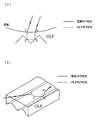
図1(a)は、光ガイドにおける光の反射及び伝送を説明するために光学ライティングフィルムの一部分を示した断面図で、図1(b)は、光ガイドにおける光の反射及び伝送を説明するために光学ライティングフィルムの一部分を示した斜視図である。但し、理解の便宜上、平滑な内面を上側とし、プリズム形状を施した外面を下側として示した。 FIG. 1A is a cross-sectional view showing a part of an optical writing film for explaining the reflection and transmission of light in the light guide, and FIG. 1B explains the reflection and transmission of light in the light guide. FIG. 4 is a perspective view showing a part of an optical writing film. However, for convenience of understanding, the smooth inner surface is shown as the upper side, and the prism-shaped outer surface is shown as the lower side.
図1(a)及び(b)を参照すれば、光源(未図示)からの光は矢印のように、平滑内面から屈折して光学ライティングフィルム内に入射し(第1地点)、当該外側へ向かう光は外面のプリズム形状の二側面で反射され(第2地点及び第3地点)、そして、光ライティングフィルムの内面で屈折して(第4地点)、光ガイド内部に再入力される。このような全反射過程の繰り返しに従って光は、実質的に光ガイドの長手方向に沿って進んでいくことになる。したがって、光学ライティングフィルムを活用すれば、光源による光の伝送能力を向上させることができる。
上記のような従来の照明システムにおける光ガイドは、光学ライティングフィルムを活用して光源による光の伝送能力を向上させているが、光源からの距離に応じて照度に顕著な差が出ることが知られている。即ち、従来の照明システムにおける光ガイドは、その内部の光伝達と外部への光放出との関係を適切に制御することが難しく、光ガイドの長手方向に沿って均一な輝度を得ることが難しいという改善点がある。 The light guide in the conventional illumination system as described above uses an optical lighting film to improve the light transmission capability of the light source, but it is known that there is a significant difference in illuminance depending on the distance from the light source. It has been. In other words, it is difficult for the light guide in the conventional illumination system to properly control the relationship between the light transmission inside and the light emission to the outside, and it is difficult to obtain uniform brightness along the longitudinal direction of the light guide. There is an improvement point.
本発明はこのような課題を解決するためのものであり、長手方向に沿って均一に光を分配することができる構造を持つ光ガイド及びこれを用いた照明システムを提供することを目的とする。また、内外両面に所定形状をもつ光学ライティングフィルムを製造する方法及び装置を提供することを別の目的とする。 The present invention is intended to solve such problems, and an object thereof is to provide a light guide having a structure capable of uniformly distributing light along the longitudinal direction and an illumination system using the same. . Another object is to provide a method and apparatus for manufacturing an optical writing film having a predetermined shape on both the inside and outside surfaces.
本発明の照明システムは、光源部から内側に入力された光を内部伝送しつつ外面から放出する筒状の光ガイドを含んで構成され、その光ガイドは、中空の外側パイプと、該外側パイプ内に挿入され、内外面の少なくとも一方に、長手方向に沿って延び且つ互いに並行に配列された多数のプリズム形状が形成されている中空の挿入体と、を含んで構成されることを特徴とする。 The illumination system according to the present invention includes a cylindrical light guide that internally transmits light input from the light source unit and emits the light from the outer surface, and the light guide includes a hollow outer pipe and the outer pipe. And a hollow insert formed on at least one of the inner and outer surfaces extending in the longitudinal direction and having a number of prism shapes arranged in parallel to each other. To do.
また、本発明の照明システムは、光源部から内側に入力された光を内部伝送しつつ外面から放出する筒状の光ガイドを含んで構成され、その光ガイドは、中空の外側パイプと、該外側パイプ内に挿入され、内外面の一方が多数のプリズム形状を形成した面とされると共に他方が反射パターンを有する平滑面とされている中空の挿入体と、を含んで構成されることを特徴とする。 In addition, the illumination system of the present invention includes a cylindrical light guide that internally transmits light input from the light source unit and emits it from the outer surface, and the light guide includes a hollow outer pipe, A hollow insert that is inserted into the outer pipe, and one of the inner and outer surfaces is a surface having a number of prism shapes, and the other is a smooth surface having a reflection pattern. Features.
本発明によれば、長手(軸)方向に沿って均一に光を分配できる構造をもつ光ガイド及びこれを用いた照明システムを得ることができる。また、本発明によれば、内外両面に所定形状をもつ光学ライティングフィルムを連続工程で製造できる。 ADVANTAGE OF THE INVENTION According to this invention, the light guide which has a structure which can distribute light uniformly along a longitudinal (axis) direction, and an illumination system using the same can be obtained. Further, according to the present invention, an optical writing film having a predetermined shape on both the inner and outer surfaces can be manufactured in a continuous process.
以下、添付図面を参照して本発明の好ましい実施形態について詳細に説明する。図面中、同一又は対応する部分については同じ符号を付し、重複説明は省略する。 Hereinafter, preferred embodiments of the present invention will be described in detail with reference to the accompanying drawings. In the drawings, the same or corresponding parts are denoted by the same reference numerals, and redundant description is omitted.
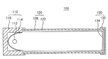
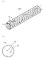
図2は、本発明の一実施形態に係る照明システムの斜視図で、図3は、図2の断面線I−Iに沿って見た要部断面図である。また、図4(a)及び(b)は、図3の挿入体の形状例を示した斜視図及び断面図である。 2 is a perspective view of an illumination system according to an embodiment of the present invention, and FIG. 3 is a cross-sectional view of a main part viewed along a cross-sectional line II in FIG. FIGS. 4A and 4B are a perspective view and a cross-sectional view showing an example of the shape of the insert shown in FIG.
図2及び図3を参照すれば、照明システム100は、光源部110、光ガイド120及び反射キャップ130を含んで構成されている。
2 and 3, the
光源部110は、電源装置(未図示)から電源の供給を受けて光を発生し、該光源部110と光学的に連結された光ガイド120へ提供する。本例の光源部110は、光を発生する光源112、光源112の背面側に配置された反射鏡114、これら光源112及び反射鏡114を収納するハウジング116を含んで構成されている。光源112は、電源装置による給電を受けて所定波長の光を発生するもので、照明システム100が設けられる環境を考慮して周知の各種光源を使用することができる。例えば、ハロゲンランプ、発光ダイオード、メタルハライドランプ、プラズマライティングを採用できる。反射鏡114は、光源112の背面側に配置され、光源112で発生した光を光ガイド120の方へ反射させる。当該反射鏡114の形状は、光を入力する光ガイド120の長さによって可変であるが、非球面反射鏡を使用するのが好ましい。このような反射鏡114は、加工性に優れた金属またはプラスチック材質から製作することができる。この場合、少なくとも反射鏡114の表面について、アルミニウムや銀のように光反射率に優れた金属物質からなる被膜を備えることが好ましい。
The
ハウジング116は、内部に形成した空間に光源112及び反射鏡114を収納し、外部環境からこれらを保護する。このようなハウジング116は、強度に優れ、放熱特性及び加工性に優れた材質、例えば、金属を使用して製作することが好ましい。当該ハウジング116の終端に光ガイド120が着脱可能に連結され、これにより、光源部110と光ガイド120とが光学的に連結される。
The
光源112で発生した光は光ガイド120の内部に入力され、この光ガイド120が、入力光をその長手方向に沿って伝送すると共に外部へ分配する。本例の光ガイド120は、外側パイプ126及び挿入体122を含んで構成されている。
The light generated by the
外側パイプ126は、中空のチューブであり、挿入体122を内部に収容して支持する。外側パイプ126の材質は、透光率が良好で、機械的性質(特に耐衝撃性)、耐熱性及び電気的安定性に優れた熱可塑性樹脂物質を使用するのが好ましい。具体的には、ポリエチレンテレフタルレート(PET)、ポリカーボネート(PC)、ポリメチルメタクリレート(PMMA)などを使用することができる。最適には、外側パイプ126をポリカーボネート、挿入体122をポリメチルメタクリレートとする組み合わせがよい。ポリメチルメタクリレートは強度が高く、壊れにくく且つ変形しにくい。また、可視光線透過率が高く、光ガイドの素材として好適である。
The
挿入体122は、内外両面にいずれも所定の形状を形成したパイプ状の光学ライティングフィルム(Optical Lighting Film;OLF)、もしくは光パイプである。図4(a)及び(b)を参照すれば、第1実施形態に係る挿入体122は、透明媒体、例えば空気が内部に充填された円状断面の中空光パイプまたはパイプ状の光学ライティングフィルムである。当該挿入体122は、光源部110から入力された光をその長手方向に沿って伝送するのに好適な構造を持つ。すなわち挿入体122は、その長手(軸)方向に沿って延び且つ互いに並行に配列された略二等辺三角形断面の多数のプリズム形状23を外面22に形成してある。さらに、本例の挿入体122は、内面24にも、長手方向に沿って延び且つ互いに並行に配列された略二等辺三角形断面の多数のプリズム形状25を形成してある。
The
このように、当該実施形態に係る挿入体122の特徴は、内面24及び外面22の両方にプリズム形状が形成されているものであり、言い換えれば、挿入体122の外面22及び内面24に、三角形状の溝が多数並列に配置されている。且つ、外面22のプリズム形状23の部位に対応する内面24の部位には溝が位置し、外面22の溝の部位に対応する内面24の部位にはプリズム形状25が位置する。
Thus, the feature of the
挿入体122を光パイプで製作する場合、透光性、機械的、熱的安定性に優れた物質、例えば、ポリカーボネート、ポリメチルメタクリレート、アクリル、ポリプロフィレン、ポリスチレン、ポリ塩化ビニルで製作することができる。中でもポリメチルメタクリレートが適している。このような光パイプの挿入体122は、上記形状に加工された押出モールドを通して長手方向に押出成形することによって、別途の付加的な作業を要せずに一体成形することができる。
When the
一方、挿入体122を光学ライティングフィルムで製作する場合、透光率が良く、機械的性質(特に耐衝撃性)、耐熱性及び電気的安定性を有する熱可塑性樹脂、例えば、ポリメチルメタクリレート(PMMA)を利用し、これをまず連続シートの形態で製作した後に外側パイプ126に対応する長さに切断して使うことができる。切断後、チューブ(パイプ)形態にロール加工し、外側パイプ126内に挿入し固定する。
On the other hand, when the
このような構造の挿入体122における光の伝送及び分配について説明する。本明細書で“入射角”とは、媒体中を進行する光が他の媒体との境界面に達したときに、この境界面の法線となす角を意味する。
The transmission and distribution of light in the
まず、挿入体122の内部に入力された光が、挿入体122と挿入体122内の媒体との屈折率の比による所定の臨界角θc以上の入射角を有したとき、周知のスネルの法則に則った全反射条件によって光は反射される。この場合における挿入体122の外側へ向かう光は、挿入体122の内側へ反射されて拘束されて実質的に挿入体122の長手方向へ進む。このとき、挿入体122内に充填されている媒体が空気であるため、光はほとんど損失することなく挿入体122の内側で導波しうる。
First, when the light input into the
一方、前記臨界角θcを下回る入射角で入射する光は、挿入体122の外面を介して外へ出射することになる。すなわち、挿入体122の内部に入力された光は、挿入体122の長手方向に伝送されつつ外部へ放出される。
On the other hand, light incident at an incident angle lower than the critical angle θc is emitted to the outside through the outer surface of the
本発明の技術思想は、上記第1実施形態に係る挿入体122の構造に制限されるものではなく、多様に変形しうるものである。以下では、挿入体122に対するいくつかの変形例について説明する。
The technical idea of the present invention is not limited to the structure of the
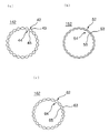
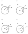
図5(a)〜(c)に、図3の挿入体の別の形態について断面図で示す。 FIGS. 5A to 5C are cross-sectional views showing other forms of the insert shown in FIG.
図5(a)を参照すれば、挿入体142は、長手方向に沿って延び且つ互いに並行に配列された略二等辺三角形断面をもつ多数のプリズム形状43を外面42に形成してある。さらに内面44にも、長手方向に沿って延び且つ互いに並行に配列された略二等辺三角形断面をもつプリズム形状45を形成してある。言い換えると、外面42及び内面44の両方に、多数の三角形状の溝が並列に設けられている。第1実施形態との違いは、外面42におけるプリズム形状43の部位に対応する内面44の部位にプリズム形状45が位置し、外面42における溝の部位に対応する内面44の部位に溝が位置することである。
Referring to FIG. 5 (a), the
図5(b)を参照すれば、挿入体152は、長手方向に沿って延び且つ互いに並行に配列された略台形形状断面をもつ多数のプリズム形状53を外面52に形成してある。そして内面54には、長手方向に沿って延び且つ互いに並行に配列された略二等辺三角形断面をもつ多数の溝55を含む。外面52に配列されたプリズム形状53の間には三角形状の溝が並列に形成されている。この例では、外面52におけるプリズム形状53の部位に対応する内面54の部位に溝55が位置し、外面52における溝の部位に対応する内面54の部位にプリズム形状が位置する。
Referring to FIG. 5 (b), the
図5(c)を参照すれば、挿入体162は、長手方向に沿って延び且つ互いに並行に配列された略台形形状断面をもつ多数のプリズム形状63を外面62に形成してある。そして内面64には、長手方向に沿って延び且つ互いに並行に配列された略二等辺三角形断面をもつ多数のプリズム形状65を形成してある。上記同様、外面62におけるプリズム形状63の間には三角形状の溝が形成され、内面64におけるプリズム形状65の間にも三角形状の溝が形成されている。本例においては、外面62におけるプリズム形状63の部位に対応する内面64の部位にプリズム形状65が位置し、外面62における溝の部位に対応する内面64の部位に溝が位置している。
Referring to FIG. 5C, the
図6(a)〜(d)に、図3の挿入体のさらに別の実施形態を断面図で示す。 FIGS. 6A to 6D are sectional views showing still another embodiment of the insert shown in FIG.
図6(a)を参照すれば、挿入体172は、長手方向に沿って延びる略三角形断面をもつ多数のプリズム形状73を並列に形成した外面72と、長手方向に沿って延びる台形形状断面をもつ多数の溝75を並列に形成した内面74と、を含んでいる。本例の場合、外面72におけるプリズム形状73の部位に対応する内面74の部位に溝75が位置する。
Referring to FIG. 6A, the
図6(b)を参照すれば、挿入体182は、長手方向に沿って延びる略三角形断面をもつ多数の溝83を並列に形成した外面82と、長手方向に沿って延びる略台形形状断面をもつ多数の溝85を並列に形成した内面84と、を含んでいる。本例の場合、外面82における溝83の部位に対応する内面84の部位に溝85が位置する。
Referring to FIG. 6B, the
図6(c)を参照すれば、挿入体192は、長手方向に沿って延びる略台形状断面をもつ多数のプリズム形状93を並列に形成した外面92と、長手方向に沿って延びる略台形状断面をもつ多数の溝95を並列に形成した内面94と、を含んでいる。本例の場合、外面92におけるプリズム形状93の部位に対応する内面94の部位に溝95が位置する。
Referring to FIG. 6C, the
図6(d)を参照すれば、挿入体202は、長手方向に沿って延びる略台形状断面をもつ多数のプリズム形状103を並列に形成した外面102と、長手方向に沿って延びる略台形状断面をもつ多数の溝105を並列に形成した内面104と、を含んでいる。本例の場合、外面102におけるプリズム形状103の間に形成された溝の部位に対応する内面104の部位に溝105が位置する。
Referring to FIG. 6D, the
図2及び図3に示す光ガイド120の終端には、反射キャップ130が着脱可能に設けられる。反射キャップ130は、光ガイド120の終端まで伝えられた光を反射して再使用することによって、光の利用効率を向上させ、光ガイド120の終端部での輝度を向上させて照度分布の均一性を向上させる。このような反射キャップ130は、キャップ部132と、キャップ部132の内側に固定された反射鏡134と、を含む。
A
キャップ部132は、反射鏡134が光ガイド120の終端に位置するように光ガイド120と着脱可能に結合される。反射鏡134は、反射キャップ130の内側に配置され、光ガイド120の終端に到達した光を反射する。このために反射鏡134の表面は、光反射度に優れた物質、例えば、アルミニウムや銀のような金属物質からなる被膜を備えていてもよい。また、反射鏡134は、平面または球面反射鏡の形態に構成することができる。反射鏡134を球面反射鏡で構成する場合、曲率が0.001以下の凹面鏡が好ましい。
The
次に、本発明に係る照明システムについて、他の実施形態を説明する。 Next, other embodiments of the illumination system according to the present invention will be described.
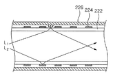
図7(a)は、図2の断面線I−Iに沿った切断図相当で示した照明システムの要部断面図、図7(b)は、図2の断面線II−IIに沿った断面図相当で示した光ガイドの要部断面図、図7(c)は、図7(a)及び(b)の挿入体の一部を示した部分斜視図である。また、図8は、図7の光ガイド内を光が伝わって分配される様相を説明するための図面である。 7A is a cross-sectional view of an essential part of the illumination system corresponding to a cutaway view taken along a cross-sectional line II in FIG. 2, and FIG. 7B is a cross-sectional view taken along a cross-sectional line II-II in FIG. FIG. 7C is a partial perspective view showing a part of the insertion body shown in FIGS. 7A and 7B. FIG. FIG. 8 is a view for explaining a state in which light is transmitted and distributed in the light guide of FIG.
図2及び図7(a)を参照すれば、本実施例に係る照明システム200は、光源部110、光ガイド220及び反射キャップ130を含んで構成される。このうち、光源部110及び反射キャップ130の構成は、前述の実施形態に係る照明システム100と同様なので、以下では説明を省略し、光ガイド220について説明する。
Referring to FIGS. 2 and 7A, the
図7(a)〜(c)を参照すれば、光ガイド220は、外側パイプ226及び挿入体222を含む。外側パイプ226は、中空のチューブであり、挿入体222を内部に収容して支持する。外側パイプ226の材質は、透光率が良好で、機械的性質(特に耐衝撃性)、耐熱性及び電気的安定性を有する熱可塑性樹脂物質が好ましい。具体的には、外側パイプ226は、ポリエチレンテレフタルレート(PET)、ポリカーボネート(PC)、ポリメチルメタクリレート(PMMA)から構成することができる。最適には、外側パイプ126をポリカーボネート、挿入体222をポリメチルメタクリレートで構成するのが良い。ポリメチルメタクリレートは強度が高く、壊れにくく且つ変形しにくい。また、可視光線透過率が高く、光源素材として好適である。
Referring to FIGS. 7A to 7C, the
挿入体222は、光学ライティングフィルムまたは光パイプとすることができる。当該挿入体222は、透明媒体、例えば空気が内部に充填された円形断面(楕円や多角形断面も可)の中空光パイプまたはパイプ状とした光学ライティングフィルムである。挿入体222は、光源部110から入力された光を長手方向に沿って伝送するのに好適な構造を持つ。
The
挿入体222の内面222bには、多数の微小プリズム形状223が長手方向に沿って形成され、微細なピッチで配列されている。各プリズム形状223の断面は、二等辺三角形、不等辺三角形、正三角形とすることができ、好ましくは、頂角が略90°の二等辺三角形がよい。一方の挿入体222の外面222aは、光ガイド220に入力された光を出射する平滑面としてあるが、当該外面222aには、光を反射できる物質、例えば、反射度に優れたAgまたはAlなどの金属物質から構成した反射パターン224を形成している。たとえば反射パターン224は、挿入体222から出ようとする光を反射し得るようなドットパターンで形成でき、このような反射パターン224は、光を反射して光ガイド220内に拘束する。これにより、挿入体222を通る光の一部は光ガイド220に沿って導光され、一部は光ガイド220の外へ出射されるので、光ガイド220の全面から従来より均等に光が出射され得る。
On the
好ましくは、挿入体222の外面222aにおいて反射パターン224が占有する面積は、光量の多い光源部110に近い方でより多く、光量の少ない反射キャップ130に近い方でより少なくするとよい。即ち、挿入体222の外面222aにおける反射パターン224の占有面積は、光源部110から距離が離れるほど減少していくようにすることができる。これにより、光源部110から遠く離れた領域に比べて相対的に光量の多い光源部110に近接する領域で、より多くの光が反射パターン224により光ガイド220の内部に拘束されるので、光源部110からの距離に関係なく光ガイド220の全領域で、均一に光が放出されるようになる。
Preferably, the area occupied by the
場合によっては、挿入体222の外面222aにプリズム形状をつくり、内面222bを平滑面とし且つ上記の反射パターン224を形成する構造も可能である。
In some cases, a structure in which a prism shape is formed on the
図7(a)〜(c)及び図8を参照すれば、まず、給電によりランプ112が発光すると、その光は光ガイド220へ入力され、また一部は背面側に配置された反射鏡114で反射されて光ガイド220へ入力される。
Referring to FIGS. 7A to 7C and FIG. 8, first, when the
光ガイド220に入った光の一部L1は、挿入体222における内面222bのプリズム形状223で屈折し、挿入体222の外面222aにおける反射パターン224が形成されていない部分に到達する。このように反射パターン224の非形成部分に向かう一部光L1は、反射により光ガイド220の内部へ戻るものと、散乱により光ガイド220の外へ放出されるものになる。
Part of the light L1 entering the
光ガイド220に入った光の残りL2は、挿入体222における内面222bのプリズム形状223で屈折し、挿入体222の外面222aにおける反射パターン224が形成されている部分に到達する。このように反射パターン224の形成部分に向かう残り光L2は、ほとんどが反射により光ガイド220の内部へ戻り、ごく一部だけが散乱により光ガイド220の外へ放出される。
The remaining light L <b> 2 entering the
以上の説明のように、本形態の反射パターン224は、光を反射して光ガイド220内部に拘束する役割で設けられている。従って、光量を考慮して、光源部110に近い領域ほど反射パターン224をたくさん形成し、光源部110から離れるほど反射パターン224を少なくすれば、光ガイド220から出射される光量が全体的に均一となりうる。
As described above, the
光ガイド220の長手方向に沿って伝送されていった光L1,L2の一部は、光ガイド220の終端に設けられた反射キャップ130の反射鏡134によって反射され、再び逆方向へ伝送される。この過程で、当該反射光も光ガイド220から外へ放出され得る。
A part of the light L1 and L2 transmitted along the longitudinal direction of the
当該実施形態に係る照明システム200では、光ガイド220内を伝わる光量と光ガイド220から外へ放出される光量とを、挿入体222に形成した反射パターン224により制御することができる。従って、光源部110からの距離に起因した照度の差を克服し、光ガイド220全領域にわたって均一な輝度を得ることが可能となる。
In the
本発明に係る照明システムについて、さらなる実施形態を説明する。 Further embodiments of the illumination system according to the present invention will be described.
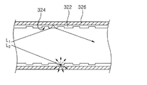
図9(a)は、図2の断面線I−Iに沿った断面図相当で示した照明システムの要部断面図、図9(b)は、図2の断面線II−IIに沿った断面図相当で示した光ガイドの要部断面図、図9(c)は、図9(a)及び(b)の挿入体の外面を概略的に示した図面である。また、図10は、図9の光ガイドを伝わって分配される光の様子を説明するための部分断面図である。 9A is a cross-sectional view of an essential part of the illumination system corresponding to a cross-sectional view taken along a cross-sectional line II in FIG. 2, and FIG. 9B is a cross-sectional view taken along a cross-sectional line II-II in FIG. FIG. 9C is a schematic cross-sectional view of the main part of the light guide shown in the cross-sectional view, and schematically shows the outer surface of the insert shown in FIGS. 9A and 9B. FIG. 10 is a partial cross-sectional view for explaining the state of light distributed through the light guide of FIG.
図2及び図9(a)〜(c)を参照すれば、本実施形態に係る照明システム300は、光源部110、光ガイド320及び反射キャップ130を含んで構成されている。光源部110及び反射キャップ130の構成は、上記実施形態に係る照明システムと同じでよいので、以下では説明を省略し、光ガイド320について説明する。
Referring to FIGS. 2 and 9A to 9C, the
図9(a)〜(c)を参照すれば、光ガイド320は、外側パイプ326及び挿入体322を含んで構成されている。外側パイプ326は中空のチューブであり、挿入体322を内部に収容して支持する。外側パイプ326の材質は、透光率が良好で、機械的性質(特に耐衝撃性)、耐熱性及び電気的安定性に優れた熱可塑性樹脂物質が好ましい。具体的には、ポリエチレンテレフタルレート(PET)、ポリカーボネート(PC)、ポリメチルメタクリレート(PMMA)を使用することができる。最適には、外側パイプ326はポリカーボネート、挿入体322はポリメチルメタクリレートで構成するのがよい。ポリメチルメタクリレートは強度が高く、壊れにくく且つ変形しにくい。また、可視光線透過率が高く、光源素材として好適である。
9A to 9C, the
挿入体322は、光学ライティングフィルムまたは光パイプを使用して形成することができる。当該挿入体322は、透明媒体、例えば空気を内部に充填した実質的円形断面の中空光パイプまたはパイプ状とした光学ライティングフィルムである。
The
挿入体322は、光源部110から入力された光を長手方向に沿って伝送するのに好適な構造を持つ。すなわち、挿入体322の外面には多数の線形プリズム形状323が微細ピッチで配列されている。また、挿入体322の内面には多数の凹部324が形成されており、本例の挿入体322は両面に所定のプリズム形状を有している。外面の各プリズム形状323の断面は、頂角が略90°で且つ頂角に隣接する両辺の長さが等しい二等辺三角形の断面とするのが好ましい。ただし、場合によっては正三角形、他の二等辺三角形、不等辺三角形であってもよい。
The
一方、挿入体322の内面に形成する凹部324は、一例として図9(c)に示すように四角形とすることができ、光源112から離れるほどにその開口径が次第に大きくなるように形成する。この凹部324は、光ガイド320に沿って導光される光を散乱させることによって、光ガイド320の外へ光を放出する役割を果たす。従って、凹部324の大きさを光源112からの距離に応じて変化させれば、光源112に近いほど挿入体322による伝送光量を多くし、光源112から離れるほどに挿入体322の外へ放出される放出光量を多くすることができる。
On the other hand, the
この照明システム300では、まず、給電により光源112が発光すると、その光は光ガイド320の内部に入力され、また一部は背面側の反射鏡114で反射されて光ガイド320内に入力される。光ガイド320に入力された光は、挿入体323によって、光ガイド320の長手方向へ伝送されると共に光ガイド320の外へ放出される。
In the
具体的に説明すると、図10に示されるように、凹部324に関わらない光L1は、挿入体322の外面に形成された複数の線形プリズム形状323により全反射されて光ガイド320の長手方向へ伝送され、一方、挿入体322の内面に形成された複数の凹部324にあたった光L2は、散乱により光ガイド320の外へ放出されて照明光となる。この凹部324は、光源112から離れるほど開口径が大きくなるので、光が凹部324にあたる確率は、光源112から離れるほど増大することになる。従って、光源112から遠くなるほどガイド内伝送光量は少なくなるけれども相対的にガイド外放出光量が増えるので、光源112からの距離に起因する輝度差を低減することができる。
More specifically, as shown in FIG. 10, the light L <b> 1 that is not related to the
光ガイド320の終端まで伝送された光は、該終端に設けられた反射キャップ130の反射鏡134によって反射され、再び逆方向へ伝送される。当該反射光も、光ガイド320の外部に放出され得る。
The light transmitted to the end of the
この照明システム300では、内外両面に所定形状を形成した挿入体322を利用することにより、光ガイド320の長手方向に沿った伝送光量と外への放出光量とを制御することができる。従って、光源部110からの距離に起因した照度の差を克服して、光ガイド320全領域にわたって均一な輝度を得ることができる。
In the
凹部形状を形成した挿入体の別の例について説明する。 Another example of the insert having a concave shape will be described.
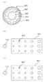
図11(a)は、挿入体の別の例を示した図9(b)相当の断面図、図11(b)及び(c)は、さらにその他の例を示した図9(c)相当の図面である。 11A is a cross-sectional view corresponding to FIG. 9B showing another example of the insert, and FIGS. 11B and 11C are equivalent to FIG. 9C showing another example. It is a drawing of.
図9に示す実施形態では、挿入体322の外面に多数の線形プリズム形状323を形成し且つ内面に多数の凹部324を形成するようにロール加工構造を採用しているが、図11(a)に示すように、内外面の構造を逆にすることもできる。すなわち、光ガイド420は、多数の線形プリズム形状422が内面に形成され、多数の凹部424が外面に形成された挿入体422を、支持パイプ(外側パイプ)426の内側に挿入して固定したものである。
In the embodiment shown in FIG. 9, a roll processing structure is adopted so that a large number of linear prism shapes 323 are formed on the outer surface of the
また、挿入体322又は挿入体422において形成される凹部324,424について、図9(c)に示した形状及び配列以外にも、図11(b)に示すような円形凹部524や、図11(c)に示すような不規則形状の凹部624とした挿入体522,622を使用することもできる。
Further, regarding the
これら実施形態においては、凹部324,424,524,624について、光源112から遠くなるにつれて開口径が変わるように構成しているが、凹部324,424,524,624の開口径は同じにしておいて、その分布度が変わるように構成することも可能である。即ち、光源112から遠くなるほど凹部324,424,524,624の密度を上げることによって、光量が相対的に豊富な光源112近くの領域と光量が相対的に少ない光源112から遠い領域とで輝度差を低減することができる。
In these embodiments, the
次に、上述のような挿入体を光学ライティングフィルムで製造する場合の製造方法及びその製造装置について図12を参照して説明する。図12は、光学ライティングフィルムを製造する一連の製造ラインを概略的に示した図面である。 Next, a manufacturing method and manufacturing apparatus for manufacturing the insert as described above with an optical writing film will be described with reference to FIG. FIG. 12 is a drawing schematically showing a series of production lines for producing an optical writing film.
この例の製造ラインは、熱可塑性樹脂2及び添加剤3を含む原料を加熱及び溶融し、ダイDを通しシート形態として熱可塑性樹脂シート4を連続的に押出す押出機Mと、該押出機Mから押出した熱可塑性樹脂シート4を、一定の厚さの熱可塑性樹脂フィルム4’に圧延する複数のカレンダーロールRと、この圧延した熱可塑性樹脂フィルム4’の表裏両面にパターンを形成して光学ライティングフィルム5を得るためのパターンロールPと、を含んでいる。
The production line in this example includes an extruder M that heats and melts a raw material including the thermoplastic resin 2 and the additive 3 and continuously extrudes the
製造時間の短縮のために、添加剤3として、赤外線硬化剤及び/又は紫外線硬化剤を添加することができるが、この場合、カレンダーロールRとパターンロールPとの間に配置され、熱可塑性樹脂フィルム4’の表裏両面に赤外線を照射する複数の赤外線ランプL1と、パターンロールPの後方に配置され、パターンロールPによって表裏両面にパターンが形成された熱可塑性樹脂フィルム4’(光学ライティングフィルム5)に紫外線を照射する複数の紫外線ランプL2と、を含むことができる。このような光硬化添加剤及びランプL1,L2は、硬化時間を短縮するために用いられる。 In order to shorten the manufacturing time, an infrared curing agent and / or an ultraviolet curing agent can be added as the additive 3. In this case, the thermoplastic resin is disposed between the calendar roll R and the pattern roll P. A plurality of infrared lamps L1 that irradiate infrared light on both the front and back surfaces of the film 4 'and a thermoplastic resin film 4' (optical writing film 5) that is disposed behind the pattern roll P and has a pattern formed on the front and back surfaces by the pattern roll P. And a plurality of ultraviolet lamps L2 for irradiating ultraviolet rays. Such photo-curing additives and lamps L1, L2 are used to shorten the curing time.
熱可塑性樹脂フィルム4’の安定した移送のために、カレンダーロールRとパターンロールPとの間に、複数の移送ロールGを配置してあってもよい。
A plurality of transfer rolls G may be arranged between the calendar roll R and the pattern roll P for stable transfer of the
本例の光学ライティングフィルム5は、熱可塑性樹脂2を使用して製作される。その熱可塑性樹脂2は、例えば、ポリカーボネートである。熱可塑性樹脂2は押出機Mにおいて周知の手法で加熱溶融され、ダイDを通してシートの形態として連続的に押出される。ダイDとしては、一般的なT−ダイを使用してもよい。 The optical writing film 5 of this example is manufactured using the thermoplastic resin 2. The thermoplastic resin 2 is, for example, polycarbonate. The thermoplastic resin 2 is heated and melted in the extruder M by a well-known method, and continuously extruded through the die D as a sheet. As the die D, a general T-die may be used.
ダイDを通して押出された熱可塑性樹脂シート4は、カレンダーロールRにより一定の厚さに圧延され、薄型の熱可塑性樹脂フィルム4’となる。ダイDを通して押出された熱可塑性樹脂シート4をカレンダーロールRで圧延する場合、2個以上のロールを使用する限り、カレンダーロールRの数は制限されない。図12に示した装置では、3個のカレンダーロールR1,R2,R3を使っている。即ち、ダイDを通して押出された熱可塑性樹脂シート4は、まず、第1カレンダーロールR1及び第2カレンダーロールR2によって一次的に圧延され、継いで、第2カレンダーロールR2及び第3カレンダーロールR3によって二次的に圧延される。
The
熱可塑性樹脂2を加熱溶融して押出成形する場合、光硬化添加剤、例えば、赤外線硬化添加剤や紫外線硬化添加剤を利用すれば、硬化に必要とする時間を短縮して光学ライティングフィルム5の製造時間を節減することができる。添加剤3として赤外線硬化添加剤を使用する場合、熱可塑性樹脂フィルム4’の表裏両面をパターンロールPで加工する前段に赤外線ランプL1を配置し、熱可塑性樹脂フィルム4’の表裏両面に赤外線を照射することによって熱可塑性樹脂フィルム4’を半硬化させ、パターンを転写するのに適した状態とすることができる。
When extrusion molding is performed by heating and melting the thermoplastic resin 2, if a photo-curing additive, for example, an infrared curing additive or an ultraviolet curing additive is used, the time required for curing is shortened and the optical writing film 5 is formed. Manufacturing time can be saved. When an infrared curing additive is used as the additive 3, an infrared lamp L1 is arranged before the front and back surfaces of the
半硬化状態の熱可塑性樹脂フィルム4’は、移送ロールGに沿って移動し、パターンロールP1,P2の間に挟み込まれて、パターンロールP1,P2の各表面に刻印されたパターンが熱可塑性樹脂フィルム4’の表裏両面に転写される。光学ライティングフィルム5は、例えば、図9(b)に示したような内外面(表面)構造をもつもので、外面に線形プリズム形状322のアレイを形成し且つ内面に凹部324を形成するものである。すなわち、パターンロールP1の表面には線形プリズム形状322に対応するパターンが刻まれており、パターンロールP2の表面には凹部324に対応するパターンが刻まれている。これらパターンロールP1,P2に挟持された熱可塑性樹脂フィルム4’は、パターンロールP1,P2の回転により前方(後段)へ移動していき、これに伴ってパターンロールP1,P2の表面に刻印されたパターンが熱可塑性樹脂フィルム4’の表裏両面に転写されていく。
The semi-cured
添加剤3として紫外線硬化添加剤を使用する場合、熱可塑性樹脂フィルム4’の表裏両面をパターンロールPで加工する段階の後に、紫外線ランプL2を配置して、熱可塑性樹脂フィルム4’の表裏両面に紫外線を照射することによって硬化させることができる。完全に硬化した熱可塑性樹脂フィルム4’は、連続シート形態の光学ライティングフィルム5となって取り出される。
When an ultraviolet curing additive is used as the additive 3, after the step of processing the front and back surfaces of the
本製造方法によれば、表裏両面に所定形状を形成した光学ライティングフィルム5を、連続シート形態で製作できる長所がある。 According to this manufacturing method, there is an advantage that the optical writing film 5 having a predetermined shape on both the front and back surfaces can be manufactured in the form of a continuous sheet.
以上説明の実施形態は、本発明の例示の目的で開示したものであり、本分野で通常の知識を有した当業者であれば、本発明の思想と範囲内で様々な修正、変更、付加が可能である。すなわち、このような修正、変更及び付加は本発明の特許請求の範囲に属するものである。 The embodiments described above are disclosed for the purpose of illustrating the present invention, and those skilled in the art having ordinary knowledge in this field will be able to make various modifications, changes and additions within the spirit and scope of the present invention. Is possible. In other words, such modifications, changes, and additions belong to the scope of the claims of the present invention.
100 照明システム
110 光源部
112 光源
114 反射鏡
116 ハウジング
120 光ガイド
122 挿入体
126 外側パイプ
130 反射キャップ
132 キャップ部
134 反射鏡
DESCRIPTION OF
Claims (21)
前記光ガイドは、
中空の外側パイプと、
該外側パイプ内に挿入され、内外面の少なくとも一方に、長手方向に沿って延び且つ互いに並行に配列された多数のプリズム形状が形成されている中空の挿入体と、
を含んで構成されることを特徴とする照明システム。 It includes a cylindrical light guide that emits from the outer surface while internally transmitting light input from the light source unit,
The light guide is
A hollow outer pipe,
A hollow insert that is inserted into the outer pipe and has a plurality of prism shapes formed on at least one of the inner and outer surfaces extending in the longitudinal direction and arranged in parallel with each other;
A lighting system comprising:
該プリズム形状が前記挿入体の内外面で互いに異なっていることを特徴とする請求項1に記載の照明システム。 A number of prism shapes extending along the longitudinal direction and arranged in parallel to each other are formed on both the inner and outer surfaces of the insert,
The illumination system according to claim 1, wherein the prism shapes are different from each other on the inner and outer surfaces of the insert.
前記光ガイドは、
中空の外側パイプと、
該外側パイプ内に挿入され、内外面の一方が多数のプリズム形状を形成した面とされると共に他方が反射パターンを有する平滑面とされている中空の挿入体と、
を含んで構成されることを特徴とする照明システム。 It includes a cylindrical light guide that emits from the outer surface while internally transmitting light input from the light source unit,
The light guide is
A hollow outer pipe,
A hollow insert inserted into the outer pipe, wherein one of the inner and outer surfaces is a surface having a number of prism shapes and the other is a smooth surface having a reflection pattern;
A lighting system comprising:
Applications Claiming Priority (3)
| Application Number | Priority Date | Filing Date | Title |
|---|---|---|---|
| KR1020060033586A KR101233199B1 (en) | 2006-04-13 | 2006-04-13 | Light pipe with structured inside and outside surface |
| KR1020060053199A KR100794351B1 (en) | 2006-06-13 | 2006-06-13 | Illuminating system utilizing light guide |
| KR1020060066761A KR20080007741A (en) | 2006-07-18 | 2006-07-18 | Optical lighting film, method and apparatus for manufacturing the same, and illuminating system having the same |
Publications (1)
| Publication Number | Publication Date |
|---|---|
| JP2007287657A true JP2007287657A (en) | 2007-11-01 |
Family
ID=37885897
Family Applications (1)
| Application Number | Title | Priority Date | Filing Date |
|---|---|---|---|
| JP2006345544A Withdrawn JP2007287657A (en) | 2006-04-13 | 2006-12-22 | Lighting system using light guide |
Country Status (4)
| Country | Link |
|---|---|
| US (1) | US7658514B2 (en) |
| EP (1) | EP1845304B1 (en) |
| JP (1) | JP2007287657A (en) |
| CA (1) | CA2571929C (en) |
Cited By (3)
| Publication number | Priority date | Publication date | Assignee | Title |
|---|---|---|---|---|
| KR100988627B1 (en) | 2008-05-20 | 2010-10-18 | 엘지전자 주식회사 | An optical film and a illuminating device comprising the same |
| JP2015076279A (en) * | 2013-10-09 | 2015-04-20 | パナソニックIpマネジメント株式会社 | Lighting fixture |
| JP2016518685A (en) * | 2013-04-10 | 2016-06-23 | スリーエム イノベイティブ プロパティズ カンパニー | Remote illumination light duct |
Families Citing this family (18)
| Publication number | Priority date | Publication date | Assignee | Title |
|---|---|---|---|---|
| KR100891305B1 (en) * | 2007-04-04 | 2009-04-06 | 엘지전자 주식회사 | Illumination device |
| US8322881B1 (en) | 2007-12-21 | 2012-12-04 | Appalachian Lighting Systems, Inc. | Lighting fixture |
| KR100988621B1 (en) * | 2008-05-07 | 2010-10-20 | 엘지전자 주식회사 | Optical pipe and illuminating apparatus comprising the same |
| KR100988623B1 (en) * | 2008-05-08 | 2010-10-20 | 엘지전자 주식회사 | Optical pipe and illuminating apparatus comprising the same |
| US8075167B2 (en) * | 2008-05-20 | 2011-12-13 | Lg Electronics Inc. | Optical film and illuminating device having the same |
| KR101370917B1 (en) * | 2009-08-14 | 2014-03-24 | 엘지전자 주식회사 | Illuminator |
| US8827504B2 (en) * | 2010-06-18 | 2014-09-09 | Rambus Delaware Llc | Light bulb using solid-state light sources |
| TW201326675A (en) * | 2011-12-19 | 2013-07-01 | Dongguan Masstop Liquid Crystal Display Co Ltd | Lighting fixture |
| US9091411B2 (en) | 2012-11-02 | 2015-07-28 | Osram Sylvania Inc. | Illumination techniques and devices |
| US10302275B2 (en) | 2013-06-19 | 2019-05-28 | Bright View Technologies Corporation | Microstructure-based diffusers for creating batwing lighting patterns |
| US10072816B2 (en) | 2013-06-19 | 2018-09-11 | Bright View Technologies Corporation | Microstructure-based optical diffusers for creating batwing and other lighting patterns |
| US9765949B2 (en) | 2013-07-26 | 2017-09-19 | Bright View Technologies Corporation | Shaped microstructure-based optical diffusers for creating batwing and other lighting patterns |
| US9046637B1 (en) * | 2014-02-25 | 2015-06-02 | 3M Innovative Properties Company | Tubular lighting systems with inner and outer structured surfaces |
| US10161593B2 (en) | 2014-02-25 | 2018-12-25 | 3M Innovative Properties Company | Solid state lighting device with virtual filament(s) |
| US20160327241A1 (en) * | 2015-05-04 | 2016-11-10 | 3M Innovative Properties Company | Luminaire assembly |
| CN207164302U (en) * | 2017-09-29 | 2018-03-30 | 京东方科技集团股份有限公司 | Light guide plate, backlight module and display module |
| US10900627B1 (en) * | 2020-03-31 | 2021-01-26 | Jay N. Cullimore | Apparatus and method for simulated 3D flame effect |
| CN111677974A (en) * | 2020-05-15 | 2020-09-18 | 河南兴兴管道工程技术有限公司 | Pipeline non-excavation repairing method and repairing system |
Family Cites Families (30)
| Publication number | Priority date | Publication date | Assignee | Title |
|---|---|---|---|---|
| US2175067A (en) * | 1938-04-23 | 1939-10-03 | Holophane Co Inc | Prismatic reflector |
| US2334005A (en) * | 1941-08-05 | 1943-11-09 | Pittsburgh Reflector Company | Illuminating fixture |
| US3583786A (en) * | 1969-09-23 | 1971-06-08 | Bell Telephone Labor Inc | Optical waveguide formed of cylinders with optically smooth interfaces therebetween |
| US3902879A (en) * | 1972-08-28 | 1975-09-02 | American Optical Corp | Method of making optical fiber with porous cladding |
| DE7706786U1 (en) * | 1977-03-05 | 1977-06-08 | Jenaer Glaswerk Schott & Gen., 6500 Mainz | FIBER OPTIC WITH CROSS-LIGHT |
| US4422719A (en) * | 1981-05-07 | 1983-12-27 | Space-Lyte International, Inc. | Optical distribution system including light guide |
| US4615579A (en) * | 1983-08-29 | 1986-10-07 | Canadian Patents & Development Ltd. | Prism light guide luminaire |
| US4806289A (en) * | 1987-01-16 | 1989-02-21 | The Dow Chemical Company | Method of making a hollow light pipe |
| US4787708A (en) * | 1987-05-08 | 1988-11-29 | Tir Systems Ltd. | Apparatus for continuously controlled emission of light from prism light guide |
| US4996632A (en) * | 1988-10-07 | 1991-02-26 | Gulton Industries, Inc. | Multi-color illuminating system |
| US5233679A (en) * | 1990-04-10 | 1993-08-03 | Nobuo Oyama | Striated light diffuser and method of forming the same |
| US5258896A (en) * | 1992-06-04 | 1993-11-02 | Minnesota Mining And Manufacturing Company | Line light source |
| JPH06235918A (en) | 1993-02-09 | 1994-08-23 | Ohtsu Tire & Rubber Co Ltd :The | Light guide device |
| US5345531A (en) * | 1993-02-26 | 1994-09-06 | Fiberstars, Inc. | Optical fiber lighting apparatus and method |
| US5475785A (en) * | 1993-04-30 | 1995-12-12 | Johanson; Walter A. | Illumination devices and methods of forming same |
| US5784517A (en) * | 1993-04-30 | 1998-07-21 | Johanson; Walter A. | Illumination devices and methods of forming same |
| US5481637A (en) * | 1994-11-02 | 1996-01-02 | The University Of British Columbia | Hollow light guide for diffuse light |
| US5746502A (en) * | 1996-10-02 | 1998-05-05 | Huang; Tseng-Tsai | Receptacle structure for fluorescent lamp |
| EP0953800A1 (en) * | 1998-04-29 | 1999-11-03 | Johannes Mag. Huter | Apparatus for controlling the light emitted by an elongated light source |
| US6285814B1 (en) * | 1999-09-30 | 2001-09-04 | 3M Innovative Properties Company | Light guide luminaire |
| JP3243466B2 (en) * | 2000-01-21 | 2002-01-07 | 有限会社 トップ電子 | Lighting equipment |
| KR100356505B1 (en) * | 2000-01-22 | 2002-10-31 | 엘지전자 주식회사 | Epicycloidal light guide and illuminating facility |
| US6621973B1 (en) * | 2000-03-16 | 2003-09-16 | 3M Innovative Properties Company | Light guide with protective outer sleeve |
| US6612729B1 (en) | 2000-03-16 | 2003-09-02 | 3M Innovative Properties Company | Illumination device |
| US6637924B2 (en) * | 2000-11-15 | 2003-10-28 | Teledyne Lighting And Display Products, Inc. | Strip lighting apparatus and method |
| JP4701509B2 (en) | 2001-02-09 | 2011-06-15 | 株式会社Gsユアサ | lighting equipment |
| US6954575B2 (en) * | 2001-03-16 | 2005-10-11 | Imra America, Inc. | Single-polarization high power fiber lasers and amplifiers |
| USD472667S1 (en) * | 2001-12-24 | 2003-04-01 | Acuity Brands, Inc. | Lighting fixture housing |
| USD472668S1 (en) * | 2001-12-24 | 2003-04-01 | Acuity Brands, Inc. | Lighting fixture housing |
| US7273300B2 (en) * | 2004-08-06 | 2007-09-25 | Lumination Llc | Curvilinear LED light source |
-
2006
- 2006-12-11 US US11/636,553 patent/US7658514B2/en not_active Expired - Fee Related
- 2006-12-12 EP EP06025723.5A patent/EP1845304B1/en not_active Expired - Fee Related
- 2006-12-20 CA CA002571929A patent/CA2571929C/en not_active Expired - Fee Related
- 2006-12-22 JP JP2006345544A patent/JP2007287657A/en not_active Withdrawn
Cited By (3)
| Publication number | Priority date | Publication date | Assignee | Title |
|---|---|---|---|---|
| KR100988627B1 (en) | 2008-05-20 | 2010-10-18 | 엘지전자 주식회사 | An optical film and a illuminating device comprising the same |
| JP2016518685A (en) * | 2013-04-10 | 2016-06-23 | スリーエム イノベイティブ プロパティズ カンパニー | Remote illumination light duct |
| JP2015076279A (en) * | 2013-10-09 | 2015-04-20 | パナソニックIpマネジメント株式会社 | Lighting fixture |
Also Published As
| Publication number | Publication date |
|---|---|
| EP1845304A2 (en) | 2007-10-17 |
| CA2571929C (en) | 2009-10-27 |
| CA2571929A1 (en) | 2007-10-13 |
| EP1845304A3 (en) | 2010-06-09 |
| US20070242473A1 (en) | 2007-10-18 |
| EP1845304B1 (en) | 2015-04-15 |
| US7658514B2 (en) | 2010-02-09 |
Similar Documents
| Publication | Publication Date | Title |
|---|---|---|
| JP2007287657A (en) | Lighting system using light guide | |
| KR100988621B1 (en) | Optical pipe and illuminating apparatus comprising the same | |
| US7565050B2 (en) | Light pipe having an improved structure of prisms | |
| US11772342B2 (en) | 3D printed reflector and method for its manufacture | |
| KR100988623B1 (en) | Optical pipe and illuminating apparatus comprising the same | |
| US20080037943A1 (en) | Light pipe having a structure of enhancing an emission of a light | |
| KR100794350B1 (en) | Illuminating system using optical guide | |
| CN101055061B (en) | Light guide, method and apparatus for manufacturing the same, and illuminating system having the same | |
| KR100988626B1 (en) | Light pipe and illuminating device comprising the same | |
| KR100816015B1 (en) | Illuminating system using optical guide | |
| JP2008288050A (en) | Lighting apparatus | |
| KR100794351B1 (en) | Illuminating system utilizing light guide | |
| KR20080007741A (en) | Optical lighting film, method and apparatus for manufacturing the same, and illuminating system having the same | |
| KR100775844B1 (en) | Illuminating system utilizing half-mirror | |
| KR20090008861A (en) | An illuminating system including reflecting cap capable of increasing extract efficiency | |
| KR100775845B1 (en) | Illuminating system utilizing light guide | |
| KR101793322B1 (en) | Bulb type light device having Fresnel lens in light-incident part and light-emitting part of light cylinder | |
| KR100816014B1 (en) | Illuminating system using optical guide | |
| KR20100073628A (en) | Optical pipe and illuminating apparatus comprising the same | |
| KR100988627B1 (en) | An optical film and a illuminating device comprising the same | |
| KR101793321B1 (en) | Fluorescent light type light device having Fresnel lens in light-incident part and light-emitting part of light cylinder | |
| KR101793323B1 (en) | Light cylinder with light-emitting hole and light device using the same | |
| JP2003185846A (en) | Linear light emitter and method of manufacturing the same | |
| KR20090129204A (en) | Optical pipe and illuminating apparatus comprising the same |
Legal Events
| Date | Code | Title | Description |
|---|---|---|---|
| A300 | Application deemed to be withdrawn because no request for examination was validly filed |
Free format text: JAPANESE INTERMEDIATE CODE: A300 Effective date: 20100302 |