JP2007287362A - Fuel cell component and its manufacturing method - Google Patents
Fuel cell component and its manufacturing method Download PDFInfo
- Publication number
- JP2007287362A JP2007287362A JP2006110389A JP2006110389A JP2007287362A JP 2007287362 A JP2007287362 A JP 2007287362A JP 2006110389 A JP2006110389 A JP 2006110389A JP 2006110389 A JP2006110389 A JP 2006110389A JP 2007287362 A JP2007287362 A JP 2007287362A
- Authority
- JP
- Japan
- Prior art keywords
- layer
- metal layer
- plating
- nickel
- fuel cell
- Prior art date
- Legal status (The legal status is an assumption and is not a legal conclusion. Google has not performed a legal analysis and makes no representation as to the accuracy of the status listed.)
- Pending
Links
Images
Classifications
-
- Y—GENERAL TAGGING OF NEW TECHNOLOGICAL DEVELOPMENTS; GENERAL TAGGING OF CROSS-SECTIONAL TECHNOLOGIES SPANNING OVER SEVERAL SECTIONS OF THE IPC; TECHNICAL SUBJECTS COVERED BY FORMER USPC CROSS-REFERENCE ART COLLECTIONS [XRACs] AND DIGESTS
- Y02—TECHNOLOGIES OR APPLICATIONS FOR MITIGATION OR ADAPTATION AGAINST CLIMATE CHANGE
- Y02E—REDUCTION OF GREENHOUSE GAS [GHG] EMISSIONS, RELATED TO ENERGY GENERATION, TRANSMISSION OR DISTRIBUTION
- Y02E60/00—Enabling technologies; Technologies with a potential or indirect contribution to GHG emissions mitigation
- Y02E60/30—Hydrogen technology
- Y02E60/50—Fuel cells
-
- Y—GENERAL TAGGING OF NEW TECHNOLOGICAL DEVELOPMENTS; GENERAL TAGGING OF CROSS-SECTIONAL TECHNOLOGIES SPANNING OVER SEVERAL SECTIONS OF THE IPC; TECHNICAL SUBJECTS COVERED BY FORMER USPC CROSS-REFERENCE ART COLLECTIONS [XRACs] AND DIGESTS
- Y02—TECHNOLOGIES OR APPLICATIONS FOR MITIGATION OR ADAPTATION AGAINST CLIMATE CHANGE
- Y02P—CLIMATE CHANGE MITIGATION TECHNOLOGIES IN THE PRODUCTION OR PROCESSING OF GOODS
- Y02P70/00—Climate change mitigation technologies in the production process for final industrial or consumer products
- Y02P70/50—Manufacturing or production processes characterised by the final manufactured product
Abstract
Description
本発明は、アルミニウム系材料からなるアルミ基材の表面の少なくとも一部に耐食性被膜を有する燃料電池構成部品と、そのような燃料電池構成部品の製造方法とに関する。 The present invention relates to a fuel cell component having a corrosion-resistant coating on at least a part of the surface of an aluminum substrate made of an aluminum-based material, and a method for manufacturing such a fuel cell component.
一般に燃料電池は、電池セルとセパレータとを交互に配置・積層したものを端子板及び絶縁板を介して一対のエンドプレート間に挟着保持してなる燃料電池スタックから構成されている。固体高分子型燃料電池の場合、電池セルは、プロトン透過性の高分子材料からなる固体高分子膜を、ガス透過性及び導電性を兼備した空気側電極及び水素側電極の間に挟んで構成されている。また、燃料電池スタック内には、セパレータ等によってガス流通路が区画形成されている。燃料電池の運転に伴って、電池セルから腐食性物質(例えばフッ化水素)が揮発し又はその一部が水分に溶け込むことにより、腐食ガスや腐食液(酸性を帯びた水)が発生し、それらがガス流通路を構成する金属製部品を腐食させることが知られている。このため、燃料電池を構成する金属製部品においてガス等との接触部位の耐食性を向上させることが、重要な技術的課題となっている。 In general, a fuel cell is composed of a fuel cell stack in which battery cells and separators are alternately arranged and stacked and held between a pair of end plates via a terminal plate and an insulating plate. In the case of a polymer electrolyte fuel cell, the battery cell is configured by sandwiching a solid polymer membrane made of a proton-permeable polymer material between an air-side electrode and a hydrogen-side electrode that have both gas permeability and conductivity. Has been. In the fuel cell stack, a gas flow passage is defined by a separator or the like. With the operation of the fuel cell, corrosive substances (for example, hydrogen fluoride) are volatilized from the battery cell or part of it is dissolved in moisture, and corrosive gas and corrosive liquid (acidic water) are generated. It is known that they corrode the metal parts that make up the gas flow path. For this reason, improving the corrosion resistance of the contact part with gas etc. in the metal parts constituting the fuel cell is an important technical problem.
従来、燃料電池を構成する金属製部品の基材(母材)として、例えばステンレス鋼のような一定の耐食性を有する鉄系材料が検討されてきた。しかし、一般に鉄系材料は比重が大きいため、車載用燃料電池のように軽量化を図りたい場合には本質的に不利である。それ故、アルミニウムのような比較的安価な軽金属を用いて燃料電池構成部品を作製することが検討されているが、アルミニウムには一般に酸などに侵されやすく耐食性が低いという欠点がある。アルミ材の耐食性を改善する手法としてアルマイト処理(陽極酸化処理)が知られているが、アルマイト層(即ちアルミニウムの酸化膜)単独では、燃料電池内部の過酷な腐食性環境に耐えるだけの十分な耐食性を確保できない。このため、アルミニウム系材料を基材とする燃料電池構成部品にあっては、基材の陽極酸化で得られたアルマイト層の上に更に高分子被膜を形成することが提案されている。 Conventionally, an iron-based material having a certain corrosion resistance such as stainless steel has been studied as a base material (base material) of a metal part constituting a fuel cell. However, since iron-based materials generally have a large specific gravity, they are inherently disadvantageous when it is desired to reduce the weight, such as in-vehicle fuel cells. Therefore, it has been studied to produce a fuel cell component using a relatively inexpensive light metal such as aluminum. However, aluminum generally has a drawback that it is easily corroded by an acid or the like and has low corrosion resistance. Alumite treatment (anodizing treatment) is known as a technique for improving the corrosion resistance of aluminum materials, but an alumite layer (ie, an aluminum oxide film) alone is sufficient to withstand the severe corrosive environment inside the fuel cell. Corrosion resistance cannot be ensured. For this reason, in a fuel cell component having an aluminum-based material as a base material, it has been proposed to further form a polymer film on the alumite layer obtained by anodizing the base material.
特許文献1は、アルミニウム又はその合金からなるセパレータ基材の表面に陽極酸化法等によってアルマイト被膜を形成し、更にそのアルマイト被膜上に高分子耐熱性被膜(例えばビニル樹脂やポリイミド)を形成してなる燃料電池用セパレータを開示する。特許文献1によれば、アルマイト被膜上に高分子耐熱性被膜を形成することで、水蒸気等によるアルマイト被膜の劣化が抑制され、セパレータの耐食性が向上するとのことである。 In Patent Document 1, an alumite film is formed on the surface of a separator substrate made of aluminum or an alloy thereof by an anodic oxidation method, and a polymer heat resistant film (for example, vinyl resin or polyimide) is further formed on the alumite film. A fuel cell separator is disclosed. According to Patent Document 1, by forming a polymer heat resistant coating on the alumite coating, deterioration of the alumite coating due to water vapor or the like is suppressed, and the corrosion resistance of the separator is improved.
特許文献2は、アルミニウム表面のアルマイトの上にポリイミド被膜を電着により形成する「ポリイミド被膜を有する被覆アルマイト」を開示する。特許文献2によれば、アルマイトにその多孔の中まで侵入したポリイミド膜を構成したものを提供することにより、耐食性及び絶縁性に優れたアルマイト製品を提供できるとのことである。 Patent Document 2 discloses a “coated anodized layer having a polyimide coating” in which a polyimide coating is formed by electrodeposition on an anodized aluminum surface. According to Patent Document 2, it is possible to provide an alumite product excellent in corrosion resistance and insulation by providing an alumite having a polyimide film that penetrates into the porosity.
特許文献2は、アルマイトの上にポリイミド樹脂層を電着によって形成することを提案するが、アルマイト自体の導電性が非常に悪いため、電着法によってアルマイト上に必要な膜厚のポリイミド樹脂層を均一に形成することがそもそも難しい。ちなみに本願発明者らの実験によれば、アルマイトの表面に電着によってポリイミド樹脂層を直接形成した場合に得られるポリイミドの膜厚は10μmにも満たなかった(後記比較例1参照)。従って、特許文献2に準じてアルマイト層及びポリイミド樹脂層からなる耐食性被膜をアルミ基材上に形成したとしても、ポリイミド樹脂層はその膜厚や均一性が不十分なものしか得られず、実際には所期の目的を達成することが難しいという根本的な問題がある。本発明はかかる事情に鑑みてなされたものである。 Patent Document 2 proposes to form a polyimide resin layer on the alumite by electrodeposition, but since the conductivity of the anodized itself is very poor, the polyimide resin layer having a necessary film thickness on the alumite by the electrodeposition method. It is difficult in the first place to form a uniform. Incidentally, according to the experiments of the present inventors, the polyimide film thickness obtained when the polyimide resin layer was directly formed on the alumite surface by electrodeposition was less than 10 μm (see Comparative Example 1 described later). Therefore, even if a corrosion-resistant coating composed of an alumite layer and a polyimide resin layer is formed on an aluminum substrate according to Patent Document 2, only a polyimide resin layer with insufficient film thickness and uniformity can be obtained. Has the fundamental problem that it is difficult to achieve the intended purpose. The present invention has been made in view of such circumstances.
本発明の目的は、アルミニウム系材料からなるアルミ基材の表面の少なくとも一部に、アルマイト層及びポリイミド樹脂層を含む耐食性被膜を有する燃料電池構成部品を製造する方法であって、アルマイト層の上方に十分な膜厚のポリイミド樹脂層をほぼ均一に形成可能な燃料電池構成部品の製造方法を提供することにある。また、アルミニウム系材料からなるアルミ基材の表面の少なくとも一部に、燃料電池内部の過酷な腐食性環境に耐え得るだけの十分な耐食性を持った耐食性被膜を有してなる燃料電池構成部品を提供することにある。 An object of the present invention is a method of manufacturing a fuel cell component having a corrosion-resistant coating film including an alumite layer and a polyimide resin layer on at least a part of the surface of an aluminum base material made of an aluminum-based material, and above the anodized layer Another object of the present invention is to provide a method of manufacturing a fuel cell component capable of forming a polyimide resin layer having a sufficient film thickness almost uniformly. In addition, a fuel cell component having a corrosion-resistant coating having sufficient corrosion resistance to withstand a severe corrosive environment inside the fuel cell is provided on at least a part of the surface of an aluminum base material made of an aluminum-based material. It is to provide.
本発明は、アルミニウム系材料からなるアルミ基材の表面の少なくとも一部に耐食性被膜を有する燃料電池構成部品を製造する方法であって、前記アルミ基材に対し陽極酸化を施すことにより、そのアルミ基材の表面にアルマイト層を形成する陽極酸化工程と、陽極酸化が施されたアルミ基材に対し亜鉛めっきを施すことにより、前記アルマイト層の上に亜鉛めっき層を形成する亜鉛めっき工程と、亜鉛めっきが施されたアルミ基材に対しニッケル主体のめっきを施すことにより、前記亜鉛めっき層の上にニッケルを主要成分として含む中間金属層を形成する中間金属層形成工程と、ニッケル主体のめっきが施されたアルミ基材に対し貴金属のめっき又はスパッタリングを施すことにより、前記中間金属層の上に貴金属層を形成する貴金属層形成工程と、貴金属のめっき又はスパッタリングが施されたアルミ基材に対しポリイミド電着塗料を用いた電着塗装を施すことにより、前記貴金属層の上にポリイミド樹脂層を形成するポリイミド電着工程とを順次実行することを特徴とする燃料電池構成部品の製造方法である。 The present invention relates to a method for producing a fuel cell component having a corrosion-resistant coating on at least a part of the surface of an aluminum base material made of an aluminum-based material, and the aluminum base material is subjected to anodization. An anodic oxidation step of forming an alumite layer on the surface of the substrate, and a galvanization step of forming a galvanization layer on the anodized layer by galvanizing the anodized aluminum substrate; An intermediate metal layer forming step of forming an intermediate metal layer containing nickel as a main component on the zinc plating layer by performing nickel-based plating on the galvanized aluminum base, and nickel-based plating A noble metal layer that forms a noble metal layer on the intermediate metal layer by performing plating or sputtering of the noble metal on the aluminum base material to which the metal is applied And a polyimide electrodeposition step of forming a polyimide resin layer on the noble metal layer by applying an electrodeposition coating using a polyimide electrodeposition coating to an aluminum substrate subjected to noble metal plating or sputtering, and Are sequentially performed. A method for manufacturing a fuel cell component.
なお、この製造方法において、前記貴金属層形成工程は、ニッケル主体のめっきが施された前記アルミ基材に対して金(Au)めっきを施すことにより、前記中間金属層の上に金めっき層を形成する金めっき工程であることは好ましい。また、前記ポリイミド電着工程では、膜厚が少なくとも20μmのポリイミド樹脂層を形成することが望ましい。 In this manufacturing method, the noble metal layer forming step performs gold (Au) plating on the aluminum base material plated with nickel, thereby forming a gold plating layer on the intermediate metal layer. It is preferable that it is a gold plating process to be formed. In the polyimide electrodeposition process, it is desirable to form a polyimide resin layer having a thickness of at least 20 μm.
更に本発明は、アルミニウム系材料からなるアルミ基材の表面の少なくとも一部に耐食性被膜を有する燃料電池構成部品であって、前記耐食性被膜は、陽極酸化によって前記アルミ基材の表面に形成されたアルマイト層と、前記アルマイト層の上に形成された亜鉛めっき層と、前記亜鉛めっき層の上に形成された、ニッケルを主要成分として含む中間金属層と、前記中間金属層の上に形成された貴金属層と、前記貴金属層の上に形成された、膜厚が少なくとも20μmのポリイミド樹脂層とを積層したものであることを特徴とする燃料電池構成部品である。なお、前記貴金属層が金めっき層であることは好ましい。 Furthermore, the present invention is a fuel cell component having a corrosion-resistant coating on at least a part of the surface of an aluminum substrate made of an aluminum-based material, wherein the corrosion-resistant coating is formed on the surface of the aluminum substrate by anodic oxidation. An anodized layer, a galvanized layer formed on the anodized layer, an intermediate metal layer formed on the galvanized layer and containing nickel as a main component, and formed on the intermediate metal layer A fuel cell component comprising a noble metal layer and a polyimide resin layer having a film thickness of at least 20 μm formed on the noble metal layer. The noble metal layer is preferably a gold plating layer.
なお、本発明における各構成要件の意義、本発明の更に好ましい態様や追加的構成要件については、後記「発明を実施するための最良の形態」の欄で更に説明する。 The significance of each constituent element in the present invention, further preferred aspects of the present invention, and additional constituent elements will be further described in the section of “Best Mode for Carrying Out the Invention” below.
本発明の燃料電池構成部品の製造方法によれば、陽極酸化によってアルミ基材の表面に形成されたアルマイト層の上層に、亜鉛めっき層、ニッケルを主要成分として含む中間金属層及び貴金属層からなる複層の金属層を形成した後、ポリイミド電着塗料を用いた電着塗装を施している。即ち、ポリイミド電着時には、前記複層の金属層によってアルミ基材表面の導電性が十分に確保され、ポリイミド電着塗料の電着が円滑且つ確実に行われる。従って、本発明の方法によれば、アルマイト層の上方に十分な膜厚のポリイミド樹脂層をほぼ均一に形成することができ、その結果、アルミ基材の表面の少なくとも一部に、アルマイト層及び十分な膜厚のポリイミド樹脂層を含む耐食性被膜を有する燃料電池構成部品を確実に製造することができる。 According to the method of manufacturing a fuel cell component of the present invention, the upper layer of the alumite layer formed on the surface of the aluminum base material by anodic oxidation includes a galvanized layer, an intermediate metal layer containing nickel as a main component, and a noble metal layer. After forming a multi-layered metal layer, electrodeposition coating using a polyimide electrodeposition coating is applied. That is, at the time of polyimide electrodeposition, the conductivity of the surface of the aluminum substrate is sufficiently ensured by the multilayer metal layer, and the electrodeposition of the polyimide electrodeposition paint is performed smoothly and reliably. Therefore, according to the method of the present invention, a polyimide resin layer having a sufficient thickness can be formed almost uniformly above the alumite layer. As a result, the alumite layer and the alumite layer are formed on at least a part of the surface of the aluminum substrate. A fuel cell component having a corrosion-resistant coating including a sufficiently thick polyimide resin layer can be reliably produced.
本発明の燃料電池構成部品によれば、陽極酸化によってアルミ基材の表面に形成されたアルマイト層の上に更に、亜鉛めっき層、ニッケルを主要成分として含む中間金属層及び貴金属層からなる複層の金属層、並びに、膜厚が少なくとも20μmのポリイミド樹脂層を積層して耐食性被膜を構成している。つまり、アルミ基材表面の耐食性被膜は、最上層に位置する十分な膜厚のポリイミド樹脂層、その直下の複層の金属層(これらの中でも特に貴金属層)、更にはその下のアルマイト層といった三重の耐食性バリヤーを具備する。従って、本発明の燃料電池構成部品によれば、燃料電池内部の過酷な腐食性環境に耐え得るだけの十分な耐食性を発揮することができる。 According to the fuel cell component of the present invention, a multilayer comprising an alumite layer formed on the surface of an aluminum substrate by anodization, and further comprising a zinc plating layer, an intermediate metal layer containing nickel as a main component, and a noble metal layer The metal layer and a polyimide resin layer having a film thickness of at least 20 μm are laminated to form a corrosion-resistant film. In other words, the corrosion-resistant film on the surface of the aluminum base material is a polyimide resin layer having a sufficient thickness located in the uppermost layer, a multi-layer metal layer (especially a noble metal layer among them), and an alumite layer below it. It has a triple corrosion resistant barrier. Therefore, according to the fuel cell component of the present invention, it is possible to exhibit sufficient corrosion resistance that can withstand the severe corrosive environment inside the fuel cell.
本発明の燃料電池構成部品は、アルミニウム系材料からなるアルミ基材の表面の少なくとも一部に耐食性被膜を有するものである。燃料電池構成部品としては、燃料電池スタックを構成するためのセパレータ、ターミナルプレート(端子板)、エンドプレート、あるいは、燃料電池用のガス等の配管部品を例示することができる。なお、「アルミ基材の表面の少なくとも一部」とは、アルミ基材表面の一部又は全部をいう。 The fuel cell component of the present invention has a corrosion-resistant coating on at least a part of the surface of an aluminum substrate made of an aluminum-based material. Examples of the fuel cell component include a separator for configuring a fuel cell stack, a terminal plate (terminal plate), an end plate, or piping components such as gas for a fuel cell. The “at least part of the surface of the aluminum base” means part or all of the surface of the aluminum base.
アルミ基材を構成するアルミニウム系材料としては、純アルミニウム(Al)、Al−Mg系、Al−Si系、Al−Mg−Si系、Al−Mn系、Al−Zn系を例示することができる。なお、アルミ基材は、アルミニウム系材料の圧延材はもちろんのこと、鋳物であってもよい。また、アルミ基材は、その形状が限定されるものではなく、平板状、湾曲板状、円盤状、環状、筒状あるいはパイプ状等どのような形状であってもよい。 Examples of the aluminum-based material constituting the aluminum substrate include pure aluminum (Al), Al—Mg, Al—Si, Al—Mg—Si, Al—Mn, and Al—Zn. . The aluminum base material may be a casting as well as a rolled material of an aluminum-based material. The shape of the aluminum base material is not limited, and may be any shape such as a flat plate shape, a curved plate shape, a disc shape, an annular shape, a cylindrical shape, or a pipe shape.
アルミ基材の表面の少なくとも一部を占める耐食性被膜は、陽極酸化工程と、複層の金属層を形成する工程(亜鉛めっき工程、中間金属層形成工程及び貴金属層形成工程)と、ポリイミド電着工程とを順に経て形成される。 Corrosion-resistant coating that occupies at least a part of the surface of the aluminum substrate includes an anodizing step, a step of forming a multi-layered metal layer (zinc plating step, intermediate metal layer forming step and noble metal layer forming step), and polyimide electrodeposition It forms through a process in order.
陽極酸化工程:アルミ基材に対する陽極酸化は、アルミ基材及び対向電極を酸又はアルカリの溶液中に浸漬した状態で、アルミ基材を陽極とし対向電極を陰極とする電解処理を行うことで達成される。陽極酸化を施すことでアルミ基材の表面における酸化膜(アルマイト層)の形成が促進される。陽極酸化によりアルミ基材の表面に平均膜厚が1〜20μm(マイクロメートル)のアルマイト層を形成することが好ましい。アルマイト層の平均膜厚が1μm未満では、大気下で自然形成されるアルミ基材表面の酸化膜の膜厚との有意差がなく、基材構成金属の溶出防止にあまり貢献できない。他方、アルマイト層の平均膜厚が20μmを超えても、陽極酸化に時間を要するばかりで、基材構成金属の溶出防止効果は20μm以下の場合と比べて大差ない。 Anodization process: Anodization of aluminum substrate is achieved by electrolytic treatment with aluminum substrate as anode and counter electrode as cathode while aluminum substrate and counter electrode are immersed in acid or alkali solution. Is done. By anodizing, formation of an oxide film (alumite layer) on the surface of the aluminum substrate is promoted. It is preferable to form an alumite layer having an average film thickness of 1 to 20 μm (micrometer) on the surface of the aluminum substrate by anodization. When the average film thickness of the alumite layer is less than 1 μm, there is no significant difference from the film thickness of the oxide film on the surface of the aluminum base material that is naturally formed in the atmosphere, and it does not contribute much to the prevention of elution of the metal constituting the base material. On the other hand, even if the average film thickness of the alumite layer exceeds 20 μm, it only takes time for anodization, and the elution prevention effect of the base metal constituting metal is not much different from that in the case of 20 μm or less.
なお、前記アルマイト層は、アルミ基材の陽極酸化によって作られたものであるため、陽極酸化に特有の表面の粗さ(つまり微細な孔構造)を伴っている。この段階でアルマイト層に対する封孔処理は行わず、微細な細孔が残されたままのアルマイト層が、次の工程に提供される。 Since the alumite layer is formed by anodizing an aluminum base material, it has a surface roughness (that is, a fine pore structure) peculiar to anodization. At this stage, the alumite layer is not sealed, and an alumite layer with fine pores remaining is provided for the next step.
亜鉛めっき工程:陽極酸化が施されたアルミ基材に対し亜鉛めっきを施すことにより、前記アルマイト層の上に亜鉛めっき層が形成される。この亜鉛めっき層は、アルマイトの上に金属層の積層を可能とするための介在層又は密着強化層である。即ち、アルミ基材の表面に形成された酸化膜(アルマイト層)は、無電解めっき又は電解めっきによって金属めっき層を積層形成する際の疎外要因になる。このため例えば、亜鉛めっき用処理液で基材表面を処理してアルミニウム酸化物と亜鉛(Zn)との間で置換反応を誘発することにより、亜鉛めっき層をアルマイト層の表面に形成する。かかる亜鉛めっき層(亜鉛置換めっき層)ができることで、その上に各種の金属層を無電解めっき又は電解めっきによって容易に形成することができる。 Zinc plating step: A zinc plating layer is formed on the anodized layer by applying zinc plating to the anodized aluminum base material. This galvanized layer is an intervening layer or an adhesion reinforcing layer for enabling a metal layer to be laminated on the alumite. That is, the oxide film (alumite layer) formed on the surface of the aluminum substrate becomes a marginal factor when the metal plating layer is formed by electroless plating or electrolytic plating. Therefore, for example, the surface of the substrate is treated with a treatment solution for galvanizing to induce a substitution reaction between aluminum oxide and zinc (Zn), thereby forming a galvanized layer on the surface of the alumite layer. By forming such a zinc plating layer (zinc displacement plating layer), various metal layers can be easily formed thereon by electroless plating or electrolytic plating.
中間金属層形成工程:亜鉛めっきが施されたアルミ基材に対しニッケル主体のめっきを施すことにより、前記亜鉛めっき層の上にニッケルを主要成分として含む中間金属層が形成される。 Intermediate metal layer forming step: An intermediate metal layer containing nickel as a main component is formed on the zinc plated layer by performing nickel-based plating on the zinc-plated aluminum base material.
亜鉛めっき層上の中間金属層はニッケル(Ni)を主要成分として含む層である。「ニッケルを主要成分として含む」とは、中間金属層がニッケル若しくはその合金又はニッケル固溶体で形成されている場合はもちろんのこと、中間金属層がニッケル層と他金属の層との多層構造からなる場合をも含む意味である。かかる中間金属層の基本的役割は、その直下の亜鉛めっき層と、直上の貴金属層との間に介在して、両層間の密着強度を改善することにある。即ち、亜鉛めっき層の上に直接、貴金属層を積層しても、両層の境界又は界面で層間剥離が生じ易く、十分な密着強度が得られないという事情がある。このため、亜鉛及び貴金属の双方に対して一定の密着力を発揮するニッケルを主要成分として含む中間金属層を介在させている。また、ニッケルは他の金属に比べてレベリング性が良好であるため、ニッケルを主要成分として含む層を電気めっきにより形成した場合には、硬くて平滑度の高い表面を形成することができる。中間金属層の上面の硬度及び平滑度が高いと、中間金属層の上に形成される貴金属層の膜厚を必要最小限度にとどめることができ、貴金属の使用量を減らして製造コストの低減を図ることが容易になる。 The intermediate metal layer on the galvanized layer is a layer containing nickel (Ni) as a main component. “Nickel is included as a main component” means that the intermediate metal layer is formed of a multilayer structure of a nickel layer and another metal layer as well as the intermediate metal layer formed of nickel or an alloy thereof or a nickel solid solution. It is meant to include cases. The basic role of the intermediate metal layer is to improve the adhesion strength between the two layers by being interposed between the galvanized layer immediately below it and the noble metal layer directly above. That is, even if a noble metal layer is laminated directly on the galvanized layer, delamination is likely to occur at the boundary or interface between the two layers, and sufficient adhesion strength cannot be obtained. For this reason, an intermediate metal layer containing nickel as a main component, which exhibits a certain adhesion to both zinc and noble metal, is interposed. Further, since nickel has better leveling properties than other metals, when a layer containing nickel as a main component is formed by electroplating, a hard and highly smooth surface can be formed. If the hardness and smoothness of the upper surface of the intermediate metal layer are high, the film thickness of the noble metal layer formed on the intermediate metal layer can be kept to the minimum necessary level, and the amount of noble metal used can be reduced to reduce manufacturing costs. It becomes easy to plan.
なお、上記中間金属層を、亜鉛めっき層の上に形成された銅層と、その銅層の上に形成されたニッケル層との二層構造とすることは好ましい。つまり、亜鉛めっき層とニッケル層との間に銅層を介在させるのである。銅(Cu)は亜鉛(Zn)及びニッケル(Ni)の双方に対する親和性が高いため、亜鉛めっき層の上に直接ニッケル層を形成する場合に比べてZn/Cu/Niの積層構造とする方が、亜鉛めっき層と中間金属層との間の密着強度がより高まる。中間金属層を銅層及びニッケル層の二層構造とする場合、銅層及びニッケル層の各々を電気めっきの一種であるストライクメッキによって形成することは好ましい。ストライクメッキによれば、金属イオンの無電解めっき的な付着が抑制され、電解めっき的な付着の割合が増大するため、各めっき層の金属純度が高まる。 The intermediate metal layer preferably has a two-layer structure of a copper layer formed on the galvanized layer and a nickel layer formed on the copper layer. That is, the copper layer is interposed between the galvanized layer and the nickel layer. Since copper (Cu) has a high affinity for both zinc (Zn) and nickel (Ni), it has a Zn / Cu / Ni laminated structure compared to the case where a nickel layer is formed directly on a galvanized layer. However, the adhesion strength between the galvanized layer and the intermediate metal layer is further increased. When the intermediate metal layer has a two-layer structure of a copper layer and a nickel layer, it is preferable to form each of the copper layer and the nickel layer by strike plating which is a kind of electroplating. According to strike plating, adhesion of metal ions like electroless plating is suppressed and the rate of adhesion like electrolytic plating increases, so that the metal purity of each plating layer increases.
また、中間金属層がニッケル層を含む場合、ニッケル層は、金属拡散を抑制するバリアー層としても機能し得る。即ち、ニッケル層よりも下の層では亜鉛や銅の金属原子の拡散が生じ得るが、ニッケル層には亜鉛や銅の拡散を阻止するバリヤー性があるため、下層の亜鉛や銅がニッケル層を超えて上層の貴金属層に拡散することが防止される。このため、貴金属層を構成する貴金属の純度又は金属組成が拡散金属によって乱されることがほとんどなく、貴金属層は期待された耐食効果を長期にわたり維持可能となる。 When the intermediate metal layer includes a nickel layer, the nickel layer can also function as a barrier layer that suppresses metal diffusion. That is, diffusion of zinc or copper metal atoms may occur in layers below the nickel layer, but since the nickel layer has a barrier property that prevents the diffusion of zinc or copper, the lower layer of zinc or copper may be The diffusion to the upper noble metal layer is prevented. Therefore, the purity or metal composition of the noble metal constituting the noble metal layer is hardly disturbed by the diffusion metal, and the noble metal layer can maintain the expected corrosion resistance effect for a long time.
なお、上記中間金属層がニッケル層からなる場合の当該ニッケル層、並びに、上記中間金属層が銅層及びニッケル層の二層からなる場合の当該ニッケル層については、硫黄(S)含有量の異なるニッケル皮膜を複数重ねた「多層ニッケルめっき層」で構成されてもよい。この多層ニッケルめっき層の構成形態としては、第1層(下層)にほとんど硫黄を含まない半光沢ニッケルの層を配置すると共にその上の第2層(上層)に少量の硫黄を含む光沢ニッケルの層を配置してなる二層構造のニッケルめっき層と、半光沢ニッケルの第1層(下層)と光沢ニッケルの第2層(上層)との間に高硫黄含有ニッケルストライク層を介在させた三層構造のニッケルめっき層とを例示できる。ちなみに、高硫黄含有ニッケルストライクの硫黄含有量は0.1%のオーダーであり、光沢ニッケルの硫黄含有量は0.01%のオーダーであり、半光沢ニッケルの硫黄含有量は0.001%のオーダー以下である。 In addition, about the said nickel layer in case the said intermediate metal layer consists of nickel layers, and the said nickel layer in case the said intermediate metal layer consists of two layers, a copper layer and a nickel layer, sulfur (S) content differs. You may comprise with the "multilayer nickel plating layer" which piled up several nickel membranes. As a configuration form of this multilayer nickel plating layer, a semi-bright nickel layer containing almost no sulfur is arranged in the first layer (lower layer) and a bright nickel containing a small amount of sulfur in the second layer (upper layer) thereabove. A nickel plating layer having a two-layer structure in which layers are arranged, and a high sulfur content nickel strike layer interposed between a first layer (lower layer) of semi-bright nickel and a second layer (upper layer) of bright nickel A nickel plating layer having a layer structure can be exemplified. By the way, the sulfur content of high-sulfur nickel strike is on the order of 0.1%, the sulfur content of bright nickel is on the order of 0.01%, and the sulfur content of semi-bright nickel is 0.001%. Below order.
一般にニッケル皮膜にあっては、硫黄含有量が多くなるほど自然電位が低くなる傾向にある。このため、二層構造のニッケルめっき層の場合、仮に腐食領域が下層の半光沢ニッケルに達したとしても、光沢ニッケルと半光沢ニッケルとの間の電位関係により、下層の半光沢ニッケルは光沢ニッケルによるアノード防食をうけ、素地方向への腐食が緩和される。また、三層構造のニッケルめっき層の場合、三層間の自然電位は、中層(高硫黄含有ニッケルストライク)<上層(光沢ニッケル)<下層(半光沢ニッケル)の関係にあるため、仮に腐食領域が下層の半光沢ニッケルに達したとしても、最も卑な高硫黄含有ニッケルストライクの優先腐食によって下層(半光沢ニッケル)の腐食が大幅に緩和される。このように、中間金属層を構成するニッケル層を多層ニッケルめっき層として構成することで、耐食性能を更に向上させることができる。 Generally, in a nickel coating, the natural potential tends to decrease as the sulfur content increases. For this reason, in the case of a nickel plating layer having a two-layer structure, even if the corrosion area reaches the lower semi-bright nickel, the lower semi-bright nickel is bright nickel due to the potential relationship between the bright nickel and the semi-bright nickel. Corrosion in the direction of the substrate is mitigated due to the anode corrosion protection. In the case of a nickel plating layer with a three-layer structure, the natural potential between the three layers has a relationship of middle layer (high sulfur-containing nickel strike) <upper layer (bright nickel) <lower layer (semi-bright nickel). Even if it reaches the lower-layer semi-bright nickel, the corrosion of the lower layer (semi-bright nickel) is greatly mitigated by the preferential corrosion of the most basic high sulfur content nickel strike. Thus, the corrosion resistance can be further improved by configuring the nickel layer constituting the intermediate metal layer as a multilayer nickel plating layer.
貴金属層形成工程:ニッケル主体のめっきが施されたアルミ基材に対し貴金属のめっき又はスパッタリングを施すことにより、前記中間金属層の上に貴金属層が形成される。なお、めっき方法としては、無電解めっき又は電解めっき(電解めっきの一種であるストライクめっきを含む)があげられる。 Precious metal layer forming step: A precious metal layer is formed on the intermediate metal layer by performing precious metal plating or sputtering on an aluminum base material plated with nickel. Examples of the plating method include electroless plating or electrolytic plating (including strike plating which is a kind of electrolytic plating).
貴金属層を構成する貴金属としては、金(Au)、白金(Pt)、ルテニウム(Ru)、ロジウム(Rh)、パラジウム(Pd)、オスミウム(Os)、イリジウム(Ir)等があげられる。貴金属層を構成する貴金属としては特に、金(Au)又は白金(Pt)が好ましく、中でも金(Au)が最も好ましい。これらの貴金属は、酸などの腐食性物質に侵されにくい耐食性金属である。このため、ポリイミド樹脂層の直下に位置する貴金属層は、ポリイミド樹脂の有する耐食性能とあいまって更に優れた耐食性を燃料電池構成部品に付与する。更に、金(Au)又は白金(Pt)から選択される貴金属のめっき層は良導電体であるため、ポリイミド樹脂層を電着によって形成する際に非常に好都合な電着環境を提供し、ポリイミド樹脂層の厚膜化に大きく貢献する。 Examples of the noble metal constituting the noble metal layer include gold (Au), platinum (Pt), ruthenium (Ru), rhodium (Rh), palladium (Pd), osmium (Os), iridium (Ir), and the like. As the noble metal constituting the noble metal layer, gold (Au) or platinum (Pt) is particularly preferable, and gold (Au) is most preferable. These noble metals are corrosion resistant metals that are not easily attacked by corrosive substances such as acids. For this reason, the noble metal layer located directly under the polyimide resin layer, combined with the corrosion resistance of the polyimide resin, imparts further excellent corrosion resistance to the fuel cell component. Further, since the plating layer of noble metal selected from gold (Au) or platinum (Pt) is a good conductor, it provides a very convenient electrodeposition environment when the polyimide resin layer is formed by electrodeposition. This greatly contributes to the thickening of the resin layer.
ちなみに、陽極酸化により形成されるアルマイト層の平均膜厚が1〜20μmの場合、亜鉛めっき層の膜厚は、好ましくは0.005〜0.1μm(5〜100nm)であり、中間金属層の膜厚は、好ましくは0.1〜10μmであり、貴金属層の膜厚は、好ましくは0.001〜0.1μm(1〜100nm)である。 Incidentally, when the average thickness of the anodized layer formed by anodic oxidation is 1 to 20 μm, the thickness of the galvanized layer is preferably 0.005 to 0.1 μm (5 to 100 nm). The film thickness is preferably 0.1 to 10 μm, and the film thickness of the noble metal layer is preferably 0.001 to 0.1 μm (1 to 100 nm).
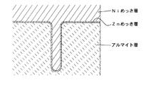
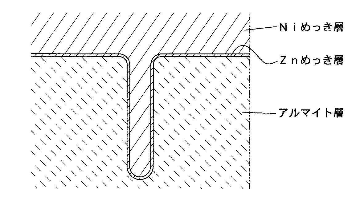
なお、前述のように前記アルマイト層は陽極酸化に特有の表面の粗さ(つまり微細な孔構造)を伴っているが、かかるアルマイト層に対して上記亜鉛めっき及びニッケル主体のめっきを施すことで、アルマイトの微細な孔内には、亜鉛めっき層及びニッケルを主要成分として含む中間金属層が進入・形成され、このことが、複層金属層のアルマイト層に対するアンカー効果を生み出す。それ故、アルマイト層の上に、亜鉛めっき層、ニッケルを主要成分として含む中間金属層及び貴金属層の三層を段階的に積層することによる化学的なアプローチに基づく密着強化に加えて、上記アンカー効果による物理的(又は機械的)な密着強化が図られるため、アルマイト層に対する複層の金属層の密着性は非常に高い。この意味で、アルミ基材の陽極酸化後に一連のめっき処理によって複層の金属層を形成することは非常に合理的といえる。 As described above, the anodized layer is accompanied by a surface roughness (that is, a fine pore structure) peculiar to anodization. By applying the zinc plating and nickel-based plating to the anodized layer, In addition, an intermediate metal layer containing zinc as a main component enters and forms in the fine holes of the alumite, and this creates an anchor effect for the alumite layer of the multilayer metal layer. Therefore, in addition to adhesion strengthening based on a chemical approach by layering three layers of a zinc plating layer, an intermediate metal layer containing nickel as a main component, and a noble metal layer on the anodized layer, the anchor Since physical (or mechanical) adhesion reinforcement due to the effect is achieved, the adhesion of the multilayer metal layer to the alumite layer is very high. In this sense, it can be said that it is very reasonable to form a multi-layered metal layer by a series of plating processes after anodizing of the aluminum base.
ポリイミド電着工程:貴金属のめっき又はスパッタリングが施されたアルミ基材に対しポリイミド電着塗料を用いた電着塗装を施すことにより、前記貴金属層の上にポリイミド樹脂層が形成される。 Polyimide electrodeposition process: A polyimide resin layer is formed on the noble metal layer by applying an electrodeposition coating using a polyimide electrodeposition coating to an aluminum base material plated or sputtered with a noble metal.
電着塗装の方法として、貴金属のめっき又はスパッタリングが施されたアルミ基材(被塗物)に負電圧を印加し、正に分極したポリイミド電着塗料を前記貴金属層の表面に析出させるカチオン電着塗装法を採用することは非常に好ましい。 As an electrodeposition coating method, a negative voltage is applied to an aluminum base material (coating object) that has been plated or sputtered with a noble metal, and a positively polarized polyimide electrodeposition paint is deposited on the surface of the noble metal layer. It is very preferable to use a coating method.
電着塗装に使用するポリイミド電着塗料としては、化学式1に示すような化学構造のポリイミドを主成分とするカチオン型ポリイミド電着塗料が最も好ましい。化学式1中、Rはアルキル鎖を、Arは芳香族構造をそれぞれ意味する。このカチオン型ポリイミド電着塗料の絶縁破壊電圧は約1000Vであり、極めて高い電気絶縁性を有している。また、このカチオン型ポリイミド電着塗料のガラス転移温度は約200℃(DSC測定)、5%質量減少温度は約400℃(TGA測定)であり、有機ポリマーとしては極めて高い耐熱性を有するものである。 As a polyimide electrodeposition paint used for electrodeposition coating, a cationic polyimide electrodeposition paint mainly composed of polyimide having a chemical structure as shown in Chemical Formula 1 is most preferable. In Chemical Formula 1, R means an alkyl chain, and Ar means an aromatic structure. The dielectric breakdown voltage of this cationic polyimide electrodeposition coating is about 1000 V, and has extremely high electrical insulation. Moreover, the glass transition temperature of this cationic polyimide electrodeposition coating is about 200 ° C. (DSC measurement), and the 5% mass reduction temperature is about 400 ° C. (TGA measurement). As an organic polymer, it has extremely high heat resistance. is there.
貴金属のめっき又はスパッタリングが施されたアルミ基材に対しカチオン型ポリイミド電着塗料を用いてカチオン電着塗装を施した後、そのポリイミド電着塗料を被塗物(基材)に加熱定着させることは好ましい。なお、電着塗装の条件や、被塗物の前処理及び後処理の方法、電着塗料の加熱定着条件等は、使用する電着塗料の種類や性質に応じて適宜選択される。 Cationic electrodeposition coating using a cationic polyimide electrodeposition coating on a precious metal plated or sputtered aluminum substrate, and then heat-fixing the polyimide electrodeposition coating to the substrate (substrate) Is preferred. The conditions for electrodeposition coating, the pre-treatment and post-treatment methods for the object to be coated, and the heat-fixing conditions for the electrodeposition paint are appropriately selected according to the type and properties of the electrodeposition paint used.
ポリイミド(PI)樹脂はそれ自体で高い耐食性を有するものであるが、ポリイミド樹脂層とその直下の貴金属層とが協働することで耐食性が更に高められる。ましてや本発明では、ポリイミド電着時の被塗物であるアルミ基材の表面には比較的導電性に優れた複層の金属層が予め形成され、この金属層の存在によりポリイミド電着が円滑且つ確実に行われて十分な膜厚のポリイミド樹脂層がほぼ均一に形成されるので、アルミ基材の耐食性は従来に比べて飛躍的に高められる。 Polyimide (PI) resin itself has high corrosion resistance, but the corrosion resistance is further enhanced by the cooperation of the polyimide resin layer and the noble metal layer directly therebelow. Furthermore, in the present invention, a multilayer metal layer having relatively excellent conductivity is formed in advance on the surface of the aluminum base material to be coated during polyimide electrodeposition, and the presence of this metal layer facilitates the polyimide electrodeposition. And since it is performed reliably and the polyimide resin layer of sufficient film thickness is formed substantially uniformly, the corrosion resistance of an aluminum base material is improved remarkably compared with the past.
なお、ポリイミド樹脂層の膜厚は少なくとも20μm必要である。その一方で、ポリイミド樹脂層の膜厚の実用上の上限値は40μmであり、好ましくは35μm以下である。即ちポリイミド樹脂層の膜厚は20〜40μm(好ましくは20〜35μm)である。 In addition, the film thickness of a polyimide resin layer needs at least 20 micrometers. On the other hand, the practical upper limit of the film thickness of the polyimide resin layer is 40 μm, preferably 35 μm or less. That is, the film thickness of the polyimide resin layer is 20 to 40 μm (preferably 20 to 35 μm).
上記一連の工程(陽極酸化工程、亜鉛めっき工程、中間金属層形成工程及び貴金属層形成工程)を経て作られる燃料電池構成部品の耐食性被膜は、陽極酸化によってアルミ基材の表面に形成されたアルマイト層と、そのアルマイト層の上に形成された亜鉛めっき層と、その亜鉛めっき層の上に形成されたニッケルを主要成分として含む中間金属層と、その中間金属層の上に形成された貴金属層と、その貴金属層の上に形成された膜厚が少なくとも20μmのポリイミド樹脂層とを積層してなるものである。つまり、アルミ基材表面の耐食性被膜は、最上層に位置する十分な膜厚のポリイミド樹脂層、その直下の複層の金属層(これらの中でも特に貴金属層)、更にはその下のアルマイト層といった三重の耐食性バリヤーを具備するものであるから、燃料電池内部の過酷な腐食性環境に耐え得るだけの十分な耐食性を発揮することができる。 The corrosion resistant coating of fuel cell components made through the above series of steps (anodizing step, galvanizing step, intermediate metal layer forming step and noble metal layer forming step) is anodized on the surface of the aluminum substrate by anodization. A layer, a galvanized layer formed on the anodized layer, an intermediate metal layer containing nickel as a main component formed on the galvanized layer, and a noble metal layer formed on the intermediate metal layer And a polyimide resin layer having a film thickness of at least 20 μm formed on the noble metal layer. In other words, the corrosion-resistant film on the surface of the aluminum base material is a polyimide resin layer having a sufficient thickness located in the uppermost layer, a multi-layer metal layer (especially a noble metal layer among them), and an alumite layer below it. Since it has a triple corrosion resistant barrier, it can exhibit sufficient corrosion resistance to withstand the severe corrosive environment inside the fuel cell.
本発明の具体例である実施例1を比較例1及び2と対比しながら説明する。なお、以下に述べる板状アルミ基材は、燃料電池構成部品を想定した耐食試験片である。 Example 1 which is a specific example of the present invention will be described in comparison with Comparative Examples 1 and 2. In addition, the plate-like aluminum base material described below is a corrosion resistance test piece assuming a fuel cell component.
[実施例1]
JIS:A1100系アルミニウムの圧延材である板状アルミ基材(縦90mm×横50mm×厚さ1mm)を準備し、この板状アルミ基材に対し、以下に述べるような条件で陽極酸化、多層金属めっき及びポリイミド電着を順次施すことにより、実施例1の耐食試験片を得た。
[Example 1]
JIS: A plate-like aluminum base material (90 mm long x 50 mm wide x 1 mm thick), which is a rolled material of A1100 series aluminum, is prepared, anodized and multilayered under the conditions described below. Corrosion resistance test pieces of Example 1 were obtained by sequentially performing metal plating and polyimide electrodeposition.
(1)陽極酸化
15%硫酸水溶液に少量の界面活性剤を加えてなる電解浴を準備し、その浴温を約20℃に調整した。この電解浴中に上記板状アルミ基材とカーボン製対向電極とを浸漬した。そして、板状アルミ基材を直流電源の陽極(+極)に、対向電極を直流電源の陰極(−極)にそれぞれ接続し、両極間に15ボルトの電圧を25分間印加することで陽極酸化を行った。この陽極酸化により、板状アルミ基材の表面に膜厚が5μmの酸化被膜(アルマイト層)を形成した。なお、陽極酸化後の基材は、イオン交換水で十分に水洗したのみであり、アルマイト層の封孔処理などは行っていない。
(1) Anodization An electrolytic bath was prepared by adding a small amount of a surfactant to a 15% sulfuric acid aqueous solution, and the bath temperature was adjusted to about 20 ° C. The plate-like aluminum substrate and the carbon counter electrode were immersed in this electrolytic bath. The plate-like aluminum substrate is connected to the anode (+ electrode) of the DC power supply, the counter electrode is connected to the cathode (−electrode) of the DC power supply, and a voltage of 15 volts is applied between the electrodes for 25 minutes. Went. By this anodic oxidation, an oxide film (alumite layer) having a film thickness of 5 μm was formed on the surface of the plate-like aluminum substrate. In addition, the base material after anodic oxidation is only sufficiently washed with ion-exchanged water, and the sealing treatment of the alumite layer is not performed.
(2)多層金属めっき
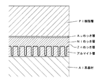
第1のめっき工程として、表面にアルマイト層が形成された板状アルミ基材を、亜鉛めっき処理液(酸化亜鉛、水酸化ナトリウム、ロッシェル塩などを含有する水溶液)に浸漬することにより、前記アルマイト層の表面に亜鉛置換めっきを施してZnめっき層を形成した。第2のめっき工程として、亜鉛置換めっきを施した板状アルミ基材を、ニッケルめっき処理液(スルファミン酸ニッケル、塩化ニッケル、硼酸などを含有する水溶液)に浸漬することにより、前記Znめっき層の上にニッケルめっきを施してNiめっき層を形成した。第3のめっき工程として、ニッケルめっきを施した板状アルミ基材を、金めっき処理液(シアン化金、シアン化ナトリウム、炭酸カリウムなどを含有する水溶液)に浸漬することにより、前記Niめっき層の上に金めっきを施してAuめっき層を形成した。こうして、板状アルミ基材の酸化被膜(アルマイト層)の表面に、Zn(膜厚:50nm)/Ni(膜厚:5μm)/Au(膜厚:10nm)の三層からなる多層金属めっき層を形成した(図1及び図2参照)。なお、多層金属めっき完了後の基材は、イオン交換水で十分に水洗した。
(2) Multi-layer metal plating As a first plating step, a plate-like aluminum substrate having an alumite layer formed on the surface is immersed in a galvanizing solution (an aqueous solution containing zinc oxide, sodium hydroxide, Rochelle salt, etc.). As a result, zinc substitution plating was performed on the surface of the alumite layer to form a Zn plating layer. As a second plating step, the plate-like aluminum substrate subjected to zinc substitution plating is immersed in a nickel plating treatment solution (an aqueous solution containing nickel sulfamate, nickel chloride, boric acid, etc.), so that the Zn plating layer is formed. A nickel plating layer was formed by performing nickel plating on the top. As a third plating step, the Ni plating layer is obtained by immersing a nickel-plated plate-like aluminum substrate in a gold plating treatment solution (an aqueous solution containing gold cyanide, sodium cyanide, potassium carbonate, etc.). An Au plating layer was formed by performing gold plating on the substrate. Thus, a multilayer metal plating layer comprising three layers of Zn (film thickness: 50 nm) / Ni (film thickness: 5 μm) / Au (film thickness: 10 nm) on the surface of the oxide film (alumite layer) of the plate-like aluminum base material. (See FIGS. 1 and 2). In addition, the base material after completion of multilayer metal plating was sufficiently washed with ion-exchanged water.
(3)ポリイミド電着
電着槽にカチオン型ポリイミド電着塗料(株式会社シミズ製商品:エレコートPI)をイオン交換水で適度な濃度に希釈した水浴を準備し、その浴温を約25℃に調整した。このポリイミド電着塗料水浴中に上記多層金属めっき後の板状アルミ基材を浸漬し、板状アルミ基材を直流電源装置の負極(−極)に接続すると共に、水浴中に浸したカーボン製対向電極を直流電源装置の正極(+極)に接続し、電流密度:5mA/cm2、電圧:200ボルトにて約2分間、電着を施した。その後、電着槽から取り出した板状アルミ基材を水洗し、エアーブロー後に予備乾燥(約110℃で15分間)を行った。そして、それを加熱装置に移し、ポリイミド電着塗料の焼付け処理(約210℃で30分間)を行った。こうして、前記多層金属めっきの最上層にあたるAuめっき層の上にポリイミド(PI)樹脂層(膜厚:30μm)を形成した(図1参照)。
(3) Polyimide electrodeposition Prepare a water bath in which a cationic polyimide electrodeposition paint (Shimizu Corporation product: Elecoat PI) is diluted to an appropriate concentration with ion-exchanged water in an electrodeposition bath, and the bath temperature is about 25 ° C. It was adjusted. The polyimide electrodeposition coating water bath is immersed in the plate-like aluminum base material after the above-mentioned multilayer metal plating, and the plate-like aluminum base material is connected to the negative electrode (-electrode) of the DC power supply device and is made of carbon soaked in the water bath. The counter electrode was connected to the positive electrode (+ electrode) of the DC power supply, and electrodeposition was performed at a current density of 5 mA / cm 2 and a voltage of 200 volts for about 2 minutes. Then, the plate-shaped aluminum base material taken out from the electrodeposition tank was washed with water, and pre-dried (about 110 ° C. for 15 minutes) after air blowing. And it moved to the heating apparatus, and the baking process (about 210 degreeC for 30 minutes) of the polyimide electrodeposition coating material was performed. Thus, a polyimide (PI) resin layer (film thickness: 30 μm) was formed on the Au plating layer which is the uppermost layer of the multilayer metal plating (see FIG. 1).
このようにして得られた実施例1の耐食試験片は、アルミ基材の表面に、アルマイト層(膜厚:5μm)、Znめっき層、Niめっき層、Auめっき層及びポリイミド樹脂層(膜厚:30μm)が積層形成されたものである。 The corrosion resistance test piece of Example 1 obtained in this way was formed on the surface of an aluminum base material with an alumite layer (film thickness: 5 μm), a Zn plating layer, a Ni plating layer, an Au plating layer, and a polyimide resin layer (film thickness). : 30 μm).
[比較例1]
実施例1と同じA1100系アルミニウム製の板状アルミ基材を準備し、この板状アルミ基材に対して実施例1と同条件にて陽極酸化を施した。そして、この陽極酸化が施された板状アルミ基材に対し、実施例1と同様にしてポリイミド電着を施した。なお、実施例1と同じ電着条件の下で、膜厚が8μmのポリイミド樹脂層が基材の酸化被膜(アルマイト層)上に形成された。このようにして得られた比較例1の耐食試験片は、アルミ基材の表面に、アルマイト層(膜厚:5μm)及びポリイミド樹脂層(膜厚:8μm)が積層形成されたものである。
[Comparative Example 1]
A plate-like aluminum substrate made of the same A1100 series aluminum as in Example 1 was prepared, and this plate-like aluminum substrate was anodized under the same conditions as in Example 1. Then, polyimide electrodeposition was applied to the plate-like aluminum base material subjected to this anodic oxidation in the same manner as in Example 1. Note that, under the same electrodeposition conditions as in Example 1, a polyimide resin layer having a film thickness of 8 μm was formed on the base oxide film (alumite layer). The corrosion resistance test piece of Comparative Example 1 obtained in this way is obtained by laminating an alumite layer (film thickness: 5 μm) and a polyimide resin layer (film thickness: 8 μm) on the surface of an aluminum base material.
[比較例2]
実施例1と同じA1100系アルミニウム製の板状アルミ基材を準備し、この板状アルミ基材に対して直接、実施例1と同様にしてポリイミド電着を施した。なお、実施例1と同じ電着条件の下で、膜厚が28μmのポリイミド樹脂層が基材上に形成された。このようにして得られた比較例2の耐食試験片は、アルミ基材の表面に、ポリイミド樹脂層(膜厚:28μm)が単層で形成されたものである。
[Comparative Example 2]
A plate-like aluminum substrate made of the same A1100 aluminum as in Example 1 was prepared, and polyimide electrodeposition was directly applied to the plate-like aluminum substrate in the same manner as in Example 1. A polyimide resin layer having a film thickness of 28 μm was formed on the substrate under the same electrodeposition conditions as in Example 1. The corrosion resistance test piece of Comparative Example 2 obtained in this way is obtained by forming a polyimide resin layer (film thickness: 28 μm) as a single layer on the surface of an aluminum substrate.
[酸腐食耐久試験]
実施例1並びに比較例1及び2の各試験片に対して、次のような試験を行った。即ち、透明な試験用水槽中に低濃度フッ酸水溶液を準備し、フッ酸水溶液の温度が80℃に保たれるように温度管理を行った。そして、各試験片をフッ酸水溶液中に浸漬してから試験片の表面被膜にブリスター(膨れ)の発生が目視で認められるまでの時間を測定した。ブリスターとは、アルミ基材とポリイミド樹脂層との間にフッ酸水溶液が進入して水素ガスが発生した結果生ずる被膜の膨れである。そして、比較例2におけるブリスター発生までの時間を基準値「1」として、実施例1及び比較例1の各々におけるブリスター発生までの時間が比較例2の何倍にあたるかを数字で示す相対評価を行った。その相対評価の結果をポリイミド樹脂層の膜厚の測定値とともに表1に示す。
[Acid corrosion durability test]
The following tests were performed on the test pieces of Example 1 and Comparative Examples 1 and 2. That is, a low concentration hydrofluoric acid aqueous solution was prepared in a transparent test water tank, and temperature control was performed so that the temperature of the hydrofluoric acid aqueous solution was maintained at 80 ° C. Then, the time from when each test piece was immersed in an aqueous hydrofluoric acid solution until the occurrence of blister (swelling) in the surface coating of the test piece was visually observed was measured. A blister is a bulge of a coating produced as a result of hydrogen gas being generated as a hydrofluoric acid aqueous solution enters between an aluminum substrate and a polyimide resin layer. Then, the relative evaluation indicating the number of times until the blister occurrence in each of Example 1 and Comparative Example 1 as a reference value “1” as a reference value “1” as a reference value “1”. went. The relative evaluation results are shown in Table 1 together with the measured values of the thickness of the polyimide resin layer.
表1中の比較例1と比較例2の膨れの相対評価を比べてわかるように、ポリイミド樹脂層の膜厚の大小にかかわらず、アルミ基材の表面にポリイミド樹脂層を単層形成した場合よりも、アルミ基材の表面にアルマイト層及びポリイミド樹脂層を積層形成した場合の方が、明らかにフッ酸に対する耐食性が高い。更に、実施例1と比較例1の膨れの相対評価を比べてわかるように、アルミ基材の表面にアルマイト層及びポリイミド樹脂層の二層を積層形成した場合よりも、アルマイト層とポリイミド樹脂層との間に複層の金属層(Zn/Ni/Au)を追加形成した場合の方が、フッ酸に対する耐食性が更に向上している。実施例1が比較例1よりも優れた耐食効果を示したのは、アルマイト層の上に導電性の高い複層の金属層(Zn/Ni/Au)を形成したことで電着によって形成されるポリイミド樹脂層の膜厚が比較例1の場合よりも大幅に厚膜化したこと、及び、ポリイミド樹脂層の直下に位置するAuめっき層が耐食性能の向上に役立っていることの二つの要因の相乗効果によるものと考えられる。 As can be seen by comparing the relative evaluation of the swelling of Comparative Example 1 and Comparative Example 2 in Table 1, when a single layer of polyimide resin layer is formed on the surface of the aluminum substrate, regardless of the thickness of the polyimide resin layer Rather, the corrosion resistance to hydrofluoric acid is clearly higher when the alumite layer and the polyimide resin layer are laminated on the surface of the aluminum substrate. Further, as can be seen by comparing the relative evaluation of the swelling of Example 1 and Comparative Example 1, an alumite layer and a polyimide resin layer are formed in comparison with the case where two layers of an alumite layer and a polyimide resin layer are formed on the surface of an aluminum substrate. In the case where a multilayer metal layer (Zn / Ni / Au) is additionally formed therebetween, the corrosion resistance against hydrofluoric acid is further improved. The reason why the corrosion resistance of Example 1 was superior to that of Comparative Example 1 was formed by electrodeposition by forming a multi-layer metal layer (Zn / Ni / Au) having high conductivity on the alumite layer. Two factors are that the film thickness of the polyimide resin layer is significantly thicker than in the case of Comparative Example 1 and that the Au plating layer located directly under the polyimide resin layer is useful for improving the corrosion resistance. This is considered to be due to the synergistic effect of.
Claims (5)
前記アルミ基材に対し陽極酸化を施すことにより、そのアルミ基材の表面にアルマイト層を形成する陽極酸化工程と、
陽極酸化が施されたアルミ基材に対し亜鉛めっきを施すことにより、前記アルマイト層の上に亜鉛めっき層を形成する亜鉛めっき工程と、
亜鉛めっきが施されたアルミ基材に対しニッケル主体のめっきを施すことにより、前記亜鉛めっき層の上にニッケルを主要成分として含む中間金属層を形成する中間金属層形成工程と、
ニッケル主体のめっきが施されたアルミ基材に対し貴金属のめっき又はスパッタリングを施すことにより、前記中間金属層の上に貴金属層を形成する貴金属層形成工程と、
貴金属のめっき又はスパッタリングが施されたアルミ基材に対しポリイミド電着塗料を用いた電着塗装を施すことにより、前記貴金属層の上にポリイミド樹脂層を形成するポリイミド電着工程と
を順次実行することを特徴とする燃料電池構成部品の製造方法。 A method of manufacturing a fuel cell component having a corrosion-resistant coating on at least a part of the surface of an aluminum base material made of an aluminum-based material,
Anodizing the aluminum substrate to form an alumite layer on the surface of the aluminum substrate;
A galvanizing step for forming a galvanized layer on the anodized layer by galvanizing the anodized aluminum base;
An intermediate metal layer forming step of forming an intermediate metal layer containing nickel as a main component on the galvanized layer by performing nickel-based plating on the galvanized aluminum substrate;
A noble metal layer forming step of forming a noble metal layer on the intermediate metal layer by plating or sputtering a noble metal on an aluminum base material plated with nickel;
A polyimide electrodeposition step of forming a polyimide resin layer on the noble metal layer is sequentially performed by applying an electrodeposition coating using a polyimide electrodeposition coating to an aluminum base material plated or sputtered with a noble metal. A method of manufacturing a fuel cell component.
陽極酸化によって前記アルミ基材の表面に形成されたアルマイト層と、
前記アルマイト層の上に形成された亜鉛めっき層と、
前記亜鉛めっき層の上に形成された、ニッケルを主要成分として含む中間金属層と、
前記中間金属層の上に形成された貴金属層と、
前記貴金属層の上に形成された、膜厚が少なくとも20μmのポリイミド樹脂層と
を積層したものであることを特徴とする燃料電池構成部品。 A fuel cell component having a corrosion-resistant coating on at least a part of the surface of an aluminum substrate made of an aluminum-based material, wherein the corrosion-resistant coating is
An anodized layer formed on the surface of the aluminum substrate by anodization;
A galvanized layer formed on the alumite layer;
An intermediate metal layer formed on the galvanized layer and containing nickel as a main component;
A noble metal layer formed on the intermediate metal layer;
A fuel cell component comprising a polyimide resin layer having a film thickness of at least 20 μm formed on the noble metal layer.
Priority Applications (1)
| Application Number | Priority Date | Filing Date | Title |
|---|---|---|---|
| JP2006110389A JP2007287362A (en) | 2006-04-13 | 2006-04-13 | Fuel cell component and its manufacturing method |
Applications Claiming Priority (1)
| Application Number | Priority Date | Filing Date | Title |
|---|---|---|---|
| JP2006110389A JP2007287362A (en) | 2006-04-13 | 2006-04-13 | Fuel cell component and its manufacturing method |
Publications (1)
| Publication Number | Publication Date |
|---|---|
| JP2007287362A true JP2007287362A (en) | 2007-11-01 |
Family
ID=38758964
Family Applications (1)
| Application Number | Title | Priority Date | Filing Date |
|---|---|---|---|
| JP2006110389A Pending JP2007287362A (en) | 2006-04-13 | 2006-04-13 | Fuel cell component and its manufacturing method |
Country Status (1)
| Country | Link |
|---|---|
| JP (1) | JP2007287362A (en) |
Cited By (2)
| Publication number | Priority date | Publication date | Assignee | Title |
|---|---|---|---|---|
| FR3047357A1 (en) * | 2016-01-28 | 2017-08-04 | Snecma | IMPROVED FUEL CELL STRUCTURE |
| WO2021049235A1 (en) * | 2019-09-13 | 2021-03-18 | 昭和電工株式会社 | Layered body and production method therefor |
Citations (5)
| Publication number | Priority date | Publication date | Assignee | Title |
|---|---|---|---|---|
| JPH0266317A (en) * | 1988-08-31 | 1990-03-06 | Taiho Kogyo Co Ltd | Slide bearing |
| JP2000106197A (en) * | 1998-09-30 | 2000-04-11 | Aisin Takaoka Ltd | Fuel cell and separator for fuel cell |
| JP2003123782A (en) * | 2001-10-17 | 2003-04-25 | Showa Denko Kk | Separator for fuel cell, its manufacturing method, and fuel cell |
| JP2004031166A (en) * | 2002-06-26 | 2004-01-29 | Kansai Paint Co Ltd | Electrostatic coating composite for fuel cell metal separator |
| JP2004047397A (en) * | 2002-05-15 | 2004-02-12 | Dainippon Printing Co Ltd | Separator member for polymer electrolyte type flat fuel cell, and polymer electrolyte type fuel cell using it |
-
2006
- 2006-04-13 JP JP2006110389A patent/JP2007287362A/en active Pending
Patent Citations (5)
| Publication number | Priority date | Publication date | Assignee | Title |
|---|---|---|---|---|
| JPH0266317A (en) * | 1988-08-31 | 1990-03-06 | Taiho Kogyo Co Ltd | Slide bearing |
| JP2000106197A (en) * | 1998-09-30 | 2000-04-11 | Aisin Takaoka Ltd | Fuel cell and separator for fuel cell |
| JP2003123782A (en) * | 2001-10-17 | 2003-04-25 | Showa Denko Kk | Separator for fuel cell, its manufacturing method, and fuel cell |
| JP2004047397A (en) * | 2002-05-15 | 2004-02-12 | Dainippon Printing Co Ltd | Separator member for polymer electrolyte type flat fuel cell, and polymer electrolyte type fuel cell using it |
| JP2004031166A (en) * | 2002-06-26 | 2004-01-29 | Kansai Paint Co Ltd | Electrostatic coating composite for fuel cell metal separator |
Cited By (2)
| Publication number | Priority date | Publication date | Assignee | Title |
|---|---|---|---|---|
| FR3047357A1 (en) * | 2016-01-28 | 2017-08-04 | Snecma | IMPROVED FUEL CELL STRUCTURE |
| WO2021049235A1 (en) * | 2019-09-13 | 2021-03-18 | 昭和電工株式会社 | Layered body and production method therefor |
Similar Documents
| Publication | Publication Date | Title |
|---|---|---|
| JP4667202B2 (en) | Aluminum material with corrosion resistant insulation coating for fuel cell components | |
| RU2326991C2 (en) | Electrode for gas extraction and method of its manufacturing | |
| JP4341838B2 (en) | Electrode cathode | |
| JP5896882B2 (en) | Composite multilayer nickel electroplating layer and electroplating method thereof | |
| US20230008403A1 (en) | Electrolysis electrode | |
| WO2010075998A2 (en) | Coated product for use in an electrochemical device and a method for producing such a product | |
| TWI600207B (en) | Fuel cell collector plate and method of manufacturing the same | |
| JP2022548205A (en) | Electrodes and methods of making and using the same | |
| Buming et al. | Effect of the current density on electrodepositing alpha-lead dioxide coating on aluminum substrate | |
| JP2007257883A (en) | Fuel cell separator and its manufacturing method | |
| JP2007287362A (en) | Fuel cell component and its manufacturing method | |
| JP2009099548A (en) | Silver-clad composite material for movable contact and its manufacturing method | |
| KR101199669B1 (en) | Method of Anode Coating for Electrolysis Equipments | |
| CN112048744B (en) | Process for improving platinum plating uniformity on surface of titanium substrate | |
| JP5336797B2 (en) | Manufacturing method of heat transfer tube and header tube of open rack type vaporizer | |
| TWI802731B (en) | Electrode for the electroplating or electrodeposition of a metal | |
| JP2006172720A (en) | Separator for fuel cell and its manufacturing method | |
| JP2011208175A (en) | Method for producing plated article, and plated article | |
| US20220178034A1 (en) | Electrode for electrolysis, and method for producing electrode for electrolysis | |
| JP2009099550A5 (en) | ||
| JP4558823B2 (en) | Silver-coated composite material for movable contact and method for producing the same | |
| JP2009099550A (en) | Silver-clad composite material for movable contact and its manufacturing method | |
| JP2009280891A (en) | Electrode plate and metal manufacturing method | |
| TWI818057B (en) | Electrode for electrolytic plating | |
| JP2018178237A (en) | Laminated plating-coated material including ruthenium |
Legal Events
| Date | Code | Title | Description |
|---|---|---|---|
| RD02 | Notification of acceptance of power of attorney |
Free format text: JAPANESE INTERMEDIATE CODE: A7422 Effective date: 20070628 |
|
| RD02 | Notification of acceptance of power of attorney |
Free format text: JAPANESE INTERMEDIATE CODE: A7422 Effective date: 20070830 |
|
| A072 | Dismissal of procedure |
Free format text: JAPANESE INTERMEDIATE CODE: A073 Effective date: 20071203 |
|
| A621 | Written request for application examination |
Free format text: JAPANESE INTERMEDIATE CODE: A621 Effective date: 20081121 |
|
| A977 | Report on retrieval |
Free format text: JAPANESE INTERMEDIATE CODE: A971007 Effective date: 20120125 |
|
| A131 | Notification of reasons for refusal |
Free format text: JAPANESE INTERMEDIATE CODE: A131 Effective date: 20120131 |
|
| A02 | Decision of refusal |
Free format text: JAPANESE INTERMEDIATE CODE: A02 Effective date: 20120529 |