JP2007285307A - Inverter-drive rotary compressor - Google Patents
Inverter-drive rotary compressor Download PDFInfo
- Publication number
- JP2007285307A JP2007285307A JP2007206039A JP2007206039A JP2007285307A JP 2007285307 A JP2007285307 A JP 2007285307A JP 2007206039 A JP2007206039 A JP 2007206039A JP 2007206039 A JP2007206039 A JP 2007206039A JP 2007285307 A JP2007285307 A JP 2007285307A
- Authority
- JP
- Japan
- Prior art keywords
- calculation
- inverter
- discharge pressure
- compressor
- control
- Prior art date
- Legal status (The legal status is an assumption and is not a legal conclusion. Google has not performed a legal analysis and makes no representation as to the accuracy of the status listed.)
- Pending
Links
Images


Abstract
Description
本発明はインバータ駆動スクリュー圧縮機に係わり、特に被圧縮気体の消費量の増減に対し吐出圧力を一定に制御するようにしたインバータ駆動スクリュー圧縮機に関する。 The present invention relates to an inverter-driven screw compressor, and more particularly to an inverter-driven screw compressor in which a discharge pressure is controlled to be constant with respect to increase / decrease in consumption of compressed gas.
特開昭55−164792号公報にはインバータによりスクリュー圧縮機の回転数を制御し容量を可変とする方法が示されている。この従来技術のものは負荷データ検出センサで負荷量を検出し、フィードバック制御に利用するものである。負荷データ検出センサは圧縮機本体の温度,圧力等のデータを読み取り、制御回路にデータを転送することが述べられている。 Japanese Patent Application Laid-Open No. 55-164792 discloses a method in which the rotational speed of a screw compressor is controlled by an inverter so that the capacity is variable. In this prior art, the load amount is detected by a load data detection sensor and used for feedback control. It is stated that the load data detection sensor reads data such as the temperature and pressure of the compressor body and transfers the data to the control circuit.
特開平7−269486号公報にはインバータ・PID制御による圧縮機の駆動方法が示されている。この従来例にはインバータ・PID制御により駆動モータの回転数を自動制御し、圧縮圧力を設定圧力に近づける制御について述べられている。 Japanese Patent Application Laid-Open No. 7-269486 discloses a method of driving a compressor by inverter / PID control. This conventional example describes control for automatically controlling the rotational speed of the drive motor by inverter / PID control so that the compression pressure approaches the set pressure.
上記特開昭55−164792号公報のものには、センサ類の種類や配置あるいは制御装置の具体的な構成(すなわちハードウェア)、圧力制御及び他の制御に対する演算方法(すなわちソフトウェア)については述べられていない。 In JP-A-55-164792, the kind and arrangement of sensors, the specific configuration of the control device (ie, hardware), the pressure control and the calculation method (ie, software) for other controls are described. It is not done.
また、特開平7−269486号公報のものにも、制御装置の具体的な構成、インバータ・PID制御の応答性や安定性についての演算方法や最適な設定値等については述べられていない。 Also, Japanese Patent Application Laid-Open No. 7-269486 does not describe the specific configuration of the control device, the calculation method for the response and stability of the inverter / PID control, the optimum set value, and the like.
インバータ駆動スクリュー圧縮機は、吐出圧力をフィードバックし外部から与えられた指示圧力と比較し、その偏差を基にしてその値を0に近付けるようPID制御やPI制御することが多い。前記PID制御やPI制御を行う制御装置は演算増幅器を中心に電子回路で構成されたアナログ電子回路を使用することが多い。インバータ駆動スクリュー圧縮機に関するPID制御におけるフィードバック制御の基本構成は、前記偏差をそれぞれ比例(P)、積分(I)、微分(D)の3つの演算を行ない、それぞれの演算結果を加算した後インバータへ電源周波数指令として出力する。この指令を基にインバータからモータへ電源周波数を出力し、圧縮機の吐出空気量を可変させ、吐出圧力を一定にする。
Inverter-driven screw compressors often perform PID control and PI control so that the discharge pressure is fed back and compared with an indicated pressure given from the outside, and the
比例、積分、微分の3つの演算(PID制御)を行なうことにより、高度な制御が可能となるが、PID制御はアナログ電子回路による演算方法であったため、演算の各乗数設定も固定されてしまい、また制御全域で同じ演算を行なうため制御特性を全体的に改善することは困難であった。そこで、制御装置をマイコンを使用したデジタル計算方式にすることにより上記不具合を解決することも実施されている。また、デジタル計算を行なうことによって、各々個々の検知データ及び出力を効率良く利用する多機能な制御装置ともなる。しかしその反面、デジタル計算により前記PID制御やPI制御を行う制御装置を使用する場合、該制御装置の入力にA/Dコンバータ、出力にD/Aコンバータを用いるが、該A/Dコンバータ及びD/Aコンバータの精度は一般的に前記アナログ電子回路の入出力よりも悪く、また分解能の高い多ビット入力のA/D、D/Aコンバータは非常に高価であり、分解能の高くないA/D、D/Aコンバータを使用すると制御特性が悪化する欠点があった。 By performing three operations (PID control): proportional, integral, and differential, advanced control is possible. However, since PID control is an arithmetic method using an analog electronic circuit, each multiplier setting for the operation is also fixed. Moreover, since the same calculation is performed in the entire control area, it is difficult to improve the control characteristics as a whole. Therefore, it is also practiced to solve the above problems by adopting a digital calculation method using a microcomputer as a control device. Further, by performing digital calculation, it becomes a multi-functional control device that efficiently uses each detection data and output. However, when using a control device that performs the PID control or PI control by digital calculation, an A / D converter is used as an input of the control device and a D / A converter is used as an output. The accuracy of the A / A converter is generally worse than the input / output of the analog electronic circuit, and the high resolution multi-bit input A / D and D / A converters are very expensive, and the resolution is not high. When the D / A converter is used, the control characteristics are deteriorated.
本発明の目的は、制御装置によるデジタル制御の多機能性を保ちつつ、信頼性の高い、高性能なインバータ駆動スクリュー圧縮機を得ることにある。 An object of the present invention is to obtain a highly reliable and high-performance inverter-driven screw compressor while maintaining the multi-functionality of digital control by a control device.
本発明の他の目的は、吐出量の急激な増減変化時、及び増減の少ない安定時のいづれに対しても、吐出圧力の変化を一定以内にすることができ、高い制御特性を維持することのできるインバータ駆動スクリュー圧縮機を得ることにある。 Another object of the present invention is to maintain a high control characteristic by making it possible to keep the discharge pressure within a certain range regardless of whether the discharge amount suddenly increases or decreases, and when the discharge amount is stable. The object is to obtain an inverter-driven screw compressor capable of
上記目的を達成するため、本発明の第1の特徴は、圧縮機と、該圧縮機から吐出された気体の吐出圧力を検出する圧力検出手段と、この検出された吐出圧力に応じて前記圧縮機を駆動する電動機の回転速度をインバータにより可変速制御する制御装置とを備えたインバータ駆動回転型圧縮機において、前記制御装置は、デジタル計算制御を行うものであって、前記吐出圧力を一定に制御するためのPID演算及びPID演算に対する比例不感帯処理、積分不感帯処理、微分不感帯処理の各演算機能を備えたことにある。 In order to achieve the above object, a first feature of the present invention is that a compressor, pressure detection means for detecting a discharge pressure of gas discharged from the compressor, and the compression in accordance with the detected discharge pressure. In an inverter-driven rotary compressor having a control device that controls the rotational speed of an electric motor that drives the motor with an inverter, the control device performs digital calculation control, and the discharge pressure is kept constant. It is provided with respective calculation functions of PID calculation for control and proportional dead band processing, integral dead band processing, and differential dead band processing for PID calculation.
本発明の第2の特徴は、圧縮機と、該圧縮機から吐出された気体の吐出圧力を検出する圧力検出手段と、この検出された吐出圧力に応じて前記圧縮機を駆動する電動機の回転速度をインバータにより可変速制御する制御装置とを備えたインバータ駆動回転型圧縮機において、前記制御装置は、デジタル計算制御を行うものであって、前記吐出圧力を一定に制御するためのPID演算及びPID演算に対する比例不感帯処理、積分不感帯処理、微分不感帯処理、比例演算分割処理、積分演算範囲限定処理の各演算機能を備え、吐出量の急激な増減状態時または増減の少ない安定状態時のとき前記各演算を実行して前記吐出圧力の変化を一定以内にすることにある。 The second feature of the present invention is that the compressor, pressure detection means for detecting the discharge pressure of the gas discharged from the compressor, and rotation of the electric motor that drives the compressor according to the detected discharge pressure. In an inverter-driven rotary compressor provided with a control device that controls the speed with an inverter by a variable speed, the control device performs digital calculation control, and performs a PID calculation for controlling the discharge pressure to be constant; Providing proportional dead zone processing, integral dead zone processing, differential dead zone processing, proportional calculation division processing, integral calculation range limiting processing for PID calculation, when the discharge amount is in a sudden increase / decrease state or in a stable state with little increase / decrease Each calculation is executed to keep the change in the discharge pressure within a certain range.
なお、上記発明において、I(積分)演算は、吐出圧力を一定値以内に制御することができるような使用空気率の範囲以内に、前記積分演算の積分値の割合を抑えると良い。 In the above invention, the I (integral) calculation may be performed by suppressing the ratio of the integral value of the integral calculation within the range of the operating air rate that allows the discharge pressure to be controlled within a certain value.
また、前記圧縮機はスクリュ−圧縮機であって、前記制御装置における演算は8ビットマイコンで行い、かつPID演算における比例演算倍率は20〜40倍であることがコスト及び性能の面で良い。 In addition, the compressor is a screw compressor, the calculation in the control device is performed by an 8-bit microcomputer, and the proportional calculation magnification in the PID calculation is 20 to 40 times in terms of cost and performance.
さらに、前記吐出圧力が目標圧力から離れる場合には微妙な吐出圧力の変化に対しても電源周波数指令を他の場合に比較し割合として大きく変化させると良い。 Furthermore, when the discharge pressure deviates from the target pressure, the power supply frequency command may be changed greatly as a ratio compared to other cases even for a subtle change in the discharge pressure.
本発明の第3の特徴は、スクリューロータを電動機により回転させ気体を圧縮するスクリュー圧縮機と、圧縮された前記気体の吐出圧力を検出する圧力検出器と、前記検出された吐出圧力に応じて前記電動機の回転速度をインバータにより可変速制御する制御装置とを備えたインバータ駆動回転型圧縮機において、前記制御装置は、デジタル計算制御により前記吐出圧力を一定に制御するようにPID演算を行なうものであって、P(比例演算)とI(積分演算)の増減が逆の場合には前記比例演算を分割して出力し、かつ前記比例演算と積分演算に不感帯を設けて吐出圧力の目標圧力付近での微妙な圧力変化を無視した制御を行なうことにある。 According to a third aspect of the present invention, a screw compressor that rotates a screw rotor with an electric motor to compress gas, a pressure detector that detects a discharge pressure of the compressed gas, and the detected discharge pressure An inverter-driven rotary compressor having a control device that controls the rotational speed of the electric motor with a variable speed by an inverter, wherein the control device performs a PID operation so as to control the discharge pressure constant by digital calculation control When the increase / decrease in P (proportional calculation) and I (integral calculation) are reversed, the proportional calculation is divided and output, and a dead zone is provided in the proportional calculation and integral calculation to set the target pressure of the discharge pressure. The purpose is to perform control ignoring subtle changes in pressure in the vicinity.
この発明において、前記比例演算の分割数は、圧縮機から下流側の空気配管容量によって0〜99分割の範囲で決定され、配管容量が大きいほど分割数も多くなるようにし、前記制御装置は吐出圧力の変動状況に応じて最適な分割数の設定を行なうと良い。 In this invention, the division number of the proportional calculation is determined in a range of 0 to 99 divisions depending on the air pipe capacity downstream from the compressor, and the division number increases as the pipe capacity increases. It is good to set the optimal number of divisions according to the pressure fluctuation situation.
本発明の第4の特徴は、スクリューロータを電動機により回転させ気体を圧縮するスクリュー圧縮機と、圧縮された前記気体の吐出圧力を検出する圧力検出器と、前記検出された吐出圧力に応じて前記電動機の回転速度をインバータにより可変速制御する制御装置とを備えたインバータ駆動回転型圧縮機において、前記制御装置は、デジタル計算制御により前記吐出圧力を一定に制御するようにPID演算を行なうものであって、吐出圧力が目標圧力付近で安定している場合でかつ吐出圧力が目標圧力から微妙に離れる時、僅かな吐出圧力の変化では電源周波数が変化しないようにP(比例),I(積分)の各演算にそれぞれ不感帯を設けたことにある。 According to a fourth aspect of the present invention, a screw compressor that rotates a screw rotor with an electric motor to compress gas, a pressure detector that detects a discharge pressure of the compressed gas, and the detected discharge pressure An inverter-driven rotary compressor having a control device that controls the rotational speed of the electric motor with a variable speed by an inverter, wherein the control device performs a PID operation so as to control the discharge pressure constant by digital calculation control When the discharge pressure is stable in the vicinity of the target pressure and when the discharge pressure slightly deviates from the target pressure, P (proportional) and I ( A dead zone is provided for each calculation of integration.
この発明において、比例演算値の最少変化量が、積分、微分の各演算値の最少変化量よりも大きい場合、比例演算不感帯の幅より積分、微分演算不感帯の幅を狭めると良い。 In the present invention, when the minimum change amount of the proportional calculation value is larger than the minimum change amount of the integral and derivative calculation values, the width of the integration and differentiation calculation dead band may be narrower than the width of the proportional calculation dead zone.
本発明の第5の特徴は、圧縮機と、該圧縮機から吐出された気体の吐出圧力を検出する圧力検出手段と、この検出された吐出圧力に応じて前記圧縮機を駆動する電動機の回転速度をインバータにより可変速制御する制御装置とを備えたインバータ駆動回転型圧縮機において、前記制御装置は、デジタル計算制御により前記吐出圧力を一定に制御するようにPID演算を行なうものであって、この各PID演算に対しそれぞれP(比例)不感帯、I(積分)不感帯、D(微分)不感帯を設け、かつ前記I(積分)演算にはさらに別の不感帯処理である積分演算範囲限定aを設け、積分演算値が上限値以上または下限値以下となったとき積分演算を行なわず、現状の積分演算値を保持することにある。 According to a fifth aspect of the present invention, there is provided a compressor, pressure detection means for detecting a discharge pressure of gas discharged from the compressor, and rotation of an electric motor that drives the compressor in accordance with the detected discharge pressure. In an inverter-driven rotary compressor provided with a control device that controls the speed by an inverter with a variable speed, the control device performs a PID operation so as to control the discharge pressure constant by digital calculation control, Each PID calculation is provided with a P (proportional) dead band, an I (integral) dead band, and a D (differential) dead band, and the I (integration) calculation is provided with an integral calculation range limitation a which is another dead band process. When the integral calculation value is equal to or higher than the upper limit value or lower than the lower limit value, the integration calculation is not performed and the current integral calculation value is held.
この発明において、前記積分演算に対してはさらに、実際に使用される空気の使用率の範囲に対し、積分値の割合の幅を、前記使用空気率と同等の幅に設定すると良い。 In the present invention, for the integral calculation, the width of the ratio of the integral value may be set to a width equivalent to the used air rate with respect to the range of the actually used air used rate.
本発明の第6の特徴は、スクリューロータをケーシング内に内蔵し電動機により前記スクリューロータを回転させて気体を圧縮するスクリュー圧縮機と、圧縮された前記気体の吐出圧力を検出しその圧力値を出力する圧力検出手段と、商用電力を異なった周波数の電力に変換するインバータと、前記検出された吐出圧力に応じて前記電動機の回転速度を可変速制御し吐出量を増減させて前記吐出圧力を一定に制御する制御装置とを備えたインバータ駆動回転型圧縮機において、前記制御装置はデジタル計算制御により行うものであって、前記吐出圧力を一定に制御する為のPID演算、及びPID演算に対する比例不感帯処理、積分不感帯処理、微分不感帯処理、比例演算分割処理、積分演算範囲限定処理の各演算機能を備え、前記制御装置へ圧力値入力のためのADコンバータの入力ビット数及び前記制御装置からのインバータへの電源周波数出力のためのDAコンバータの入力ビット数が少ない場合でも、吐出量の急激な増減状態または増減の少ない安定状態に対して、前記各演算を実行することにより演算による制御の遅れを最小限にし、安定した電源周波数指令を制御装置からインバータへ出力し、吐出圧力の変化を一定以内にすることにある。 The sixth feature of the present invention is that the screw rotor is housed in the casing and the screw rotor is rotated by an electric motor to compress the gas, and the discharge pressure of the compressed gas is detected and the pressure value is detected. A pressure detecting means for outputting, an inverter for converting commercial power into power of a different frequency, and a variable speed control of the rotation speed of the electric motor according to the detected discharge pressure to increase / decrease the discharge amount to thereby increase the discharge pressure. In an inverter-driven rotary compressor provided with a control device that is controlled to be constant, the control device performs digital calculation control, and is proportional to the PID calculation for controlling the discharge pressure constant and the PID calculation. Each of the control devices includes calculation functions of dead zone processing, integral dead zone processing, differential dead zone processing, proportional calculation division processing, and integral calculation range limiting processing. Even when the number of input bits of the AD converter for pressure value input and the number of input bits of the DA converter for outputting the power supply frequency to the inverter from the control device is small, the discharge amount suddenly increases or decreases or is stable with little increase or decrease By executing each of the above-mentioned calculations for the state, the control delay due to the calculation is minimized, a stable power frequency command is output from the control device to the inverter, and the change in the discharge pressure is within a certain range.
この発明において、前記制御装置はデータを記憶し保持する機能を有し、吐出圧力や吐出圧力の変化量と変化時間等を演算することにより圧縮機から末端までの全配管容量及び圧縮気体の使用量を把握し、使用する状況に見合った前記複数の各演算式の各乗数を自動設定し記憶する機能を有すると良い。 In this invention, the control device has a function of storing and holding data, and calculates the discharge pressure, the change amount of the discharge pressure, the change time, etc., and the total pipe capacity from the compressor to the end and the use of the compressed gas. It is preferable to have a function of grasping the quantity and automatically setting and storing each multiplier of each of the plurality of arithmetic expressions corresponding to the use situation.
本発明の第7の特徴は、スクリュ−圧縮機と、該圧縮機から吐出された気体の吐出圧力を検出する圧力検出手段と、この検出された吐出圧力に応じて前記圧縮機を駆動する電動機の回転速度をインバータにより可変速制御する制御装置とを備えたインバータ駆動回転型圧縮機において、前記制御装置は、8ビットマイコンによるデジタル計算制御を行うものであって、前記吐出圧力を一定に制御するためのPID演算及びPID演算に対する比例不感帯処理、積分不感帯処理、微分不感帯処理、比例演算分割処理、積分演算範囲限定処理の各演算機能を備え、I(積分)演算は、吐出圧力を一定値以内に制御することができるような使用空気率の範囲以内に、前記積分演算の積分値の割合を抑え、かつPID演算における比例演算倍率は20〜40倍であり、さらに前記吐出圧力が目標圧力から離れる場合には微妙な吐出圧力の変化に対しても電源周波数指令を他の場合に比較し割合として大きく変化させることにある。 According to a seventh aspect of the present invention, there are provided a screw compressor, pressure detection means for detecting a discharge pressure of gas discharged from the compressor, and an electric motor that drives the compressor in accordance with the detected discharge pressure. Inverter-driven rotary compressor equipped with a control device for variable speed control of the rotation speed of an inverter by an inverter, the control device performs digital calculation control by an 8-bit microcomputer, and controls the discharge pressure to be constant PID calculation and proportional deadband processing, integral deadband processing, differential deadband processing, differential deadband processing, proportional calculation division processing, and integral calculation range limiting processing are provided. The ratio of the integral value of the integral calculation is suppressed within the range of the operating air rate that can be controlled within the range, and the proportional calculation magnification in the PID calculation is 20 Is 40 times, further the discharge pressure is significantly alter the even power frequency command with respect to subtle changes in the discharge pressure in the case away from the target pressure as a percentage compared to the other cases.
なお、制御装置は、PID制御を含む吐出圧力の変化を一定以内にする制御、及び危険を避けるための温度や圧力等の監視制御を主として行い、安全優先のために前記監視制御の演算時間を低速にせず、前記吐出圧力の制御演算時間が低速になる場合でも、PIDを含む前記複数の演算を行なうことにより、またインバータに電源周波数指令に対する電源周波数出力のための加減速時間機能を有していることにより、高度な制御が可能となる。 The control device mainly performs control for controlling the change in discharge pressure including PID control within a certain range and monitoring control for temperature, pressure, etc. to avoid danger, and sets the calculation time of the monitoring control for safety priority. Even if the control calculation time of the discharge pressure is low without reducing the speed, the inverter has an acceleration / deceleration time function for outputting the power frequency in response to the power frequency command by performing the plurality of calculations including the PID. Therefore, advanced control is possible.
本発明によれば、制御装置によるデジタル制御の多機能性を保ちつつ、信頼性の高い、高性能なインバータ駆動スクリュー圧縮機を得ることができる。 ADVANTAGE OF THE INVENTION According to this invention, a highly reliable and high performance inverter drive screw compressor can be obtained, maintaining the multifunctionality of the digital control by a control apparatus.
また、吐出量の急激な増減変化時や、増減の少ない安定時のいづれに対しても、吐出圧力の変化を一定以内に安定化させることができ、高い制御特性を維持することができる。 In addition, the discharge pressure change can be stabilized within a certain range regardless of whether the discharge amount is suddenly increased or decreased or when the discharge amount is stable, and high control characteristics can be maintained.
さらに、被圧縮気体の使用量が変動し回転速度が不安定な時でも応答性の良い運転を続け、使用量がほぼ一定で回転速度が安定している時には安定性の良い運転を続けることができる。 Furthermore, even when the amount of compressed gas used fluctuates and the rotation speed is unstable, the operation with good responsiveness can be continued, and when the amount used is almost constant and the rotation speed is stable, the operation with good stability can be continued. it can.
インバータ駆動スクリュー圧縮機の一般的なものを図6に示す。図において、圧縮機からの吐出圧力pはフィードバックされ外部から与えられた指示圧力piと比較されて、その偏差Δpを基にしてその値を0に近付けるようPID制御やPI制御される。前記PID制御やPI制御を行う制御装置は、演算増幅器を中心に電子回路で構成されたアナログ電子回路を使用することが多い。インバータ駆動スクリュー圧縮機に関するPID制御におけるフィードバック制御の基本構成はこの図6に示すように、前記偏差Δpをそれぞれ比例、積分、微分の3つの演算を行ない、それぞれの演算結果を加算した後インバータへ電源周波数指令として出力する。この指令を基にインバータからモータへ電源周波数を出力し、圧縮機の吐出空気量を可変させ、吐出圧力pが一定になるように制御される。 A typical inverter-driven screw compressor is shown in FIG. In the figure, the discharge pressure p from the compressor is fed back and compared with an indicated pressure pi given from the outside, and PID control or PI control is performed so that the value approaches 0 based on the deviation Δp. The control device that performs the PID control and the PI control often uses an analog electronic circuit composed of an electronic circuit centering on an operational amplifier. As shown in FIG. 6, the basic configuration of the feedback control in the PID control related to the inverter-driven screw compressor performs three operations of proportionality, integration and differentiation for the deviation Δp, and adds the respective calculation results to the inverter. Output as power frequency command. Based on this command, the power supply frequency is output from the inverter to the motor, the discharge air amount of the compressor is varied, and the discharge pressure p is controlled to be constant.
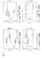
図7(a)はPID演算を行なわないで制御をした場合を示すもので、吐出圧力pが指示圧力piに近づくにつれて偏差は比例して少なくなり、限りなく0に近づくため、吐出圧力pを指示圧力piに近づけるためには非常に時間がかかってしまう。これに対し、(b)図に示すように、P(比例)演算をすることにより偏差Δpを比例倍するため、吐出圧力pが指示圧力piにある程度近づくまでは大きな出力が残るので、指示圧力pi付近まで吐出圧力pを速く上昇させることができる。また、偏差Δpに対して比例倍しているため指示圧力piから吐出圧力pが離れようとしても指示圧力piに速く戻すことができる。空気使用量が0%の場合にのみ吐出圧力pは指示圧力piに限りなく近づく。少しでも空気の使用があった場合には吐出圧力も下がる方向にあるため、偏差Δpを比例倍する
だけでは出力が不足してしまい、吐出圧力pは指示圧力piには到達しない。例えばモータの電源周波数が60Hzで、3.7m3/min, 7.0 kgf/cm2gの圧縮空気を吐出する圧縮機では、空気使用量が100%までは吐出圧力は 7.0 kgf/cm2gに維持できる。しかし、インバータ駆動の圧縮機で比例演算のみで制御した場合、吐出圧力が指示圧力 7.0 kgf/cm2gになると電源周波数は0になってしまう。空気使用量が0%なら電源周波数が0になっても吐出圧力は 7.0 kgf/cm2gになるが、空気使用量が少しでもあった場合、その分吐出圧力は指示圧力 7.0 kgf/cm2gより低くなり、支持圧力に到達しない。このような欠点があるため、積分演算を追加(PI制御)することにより、偏差Δpが0になったとしても、偏差Δpが0になった時点の積分演算値が保持されるため、比例演算だけでは到達しなかった指示圧力piまで吐出圧力pを到達させることができる。すなわち、「積分演算値の比率=空気使用量の比率」とも言える。しかし、比例演算と積分演算だけでは、特に積分演算は積分時間がかかるため、空気使用量の変化に対して電源周波数の変化が遅れてしまい、(C)図に示すように、吐出圧力pは指示圧力pi付近で昇降(オーバーシュート)してしまい、安定性に欠けてしまう。この欠点に対して、微分演算を追加(PID制御)することにより、前記オーバーシュートを抑えることができ、オーバーシュートの速さに対して微分演算の比率も変化するため、比例,積分,微分の3つの演算(PID制御)を行なうことにより高度な制御が可能となる。しかし、上記のPID制御はアナログ電子回路による演算方法であり、演算の各乗数設定も固定されてしまい、また制御全域で同じ演算を行なうため制御特性を全体的に改善することは非常に難しい。
FIG. 7A shows a case where control is performed without performing the PID calculation. The deviation decreases proportionally as the discharge pressure p approaches the command pressure pi, and approaches zero as much as possible. It takes a very long time to approach the command pressure pi. On the other hand, as shown in (b), since the deviation Δp is proportionally multiplied by calculating P (proportional), a large output remains until the discharge pressure p approaches the commanded pressure pi to some extent. The discharge pressure p can be increased rapidly to near pi. Further, since it is proportionally multiplied with respect to the deviation Δp, even if the discharge pressure p tends to be separated from the command pressure pi, it can be quickly returned to the command pressure pi. Only when the amount of air used is 0%, the discharge pressure p approaches the indicated pressure pi as much as possible. When air is used even a little, the discharge pressure is also in the direction of lowering. Therefore, the output is insufficient only by multiplying the deviation Δp proportionally, and the discharge pressure p does not reach the command pressure pi. For example, in a compressor that discharges compressed air of 3.7 m 3 / min, 7.0 kgf / cm 2 g with a motor power frequency of 60 Hz, the discharge pressure is maintained at 7.0 kgf / cm 2 g up to 100% air consumption. it can. However, when the inverter-driven compressor is controlled only by proportional calculation, the power supply frequency becomes zero when the discharge pressure reaches the indicated pressure of 7.0 kgf / cm 2 g. If the air consumption is 0%, the discharge pressure will be 7.0 kgf / cm 2 g even if the power supply frequency becomes 0. If the air consumption is even a little, the discharge pressure will be the indicated pressure 7.0 kgf / cm 2. g lower than the support pressure. Because of these disadvantages, by adding integral calculation (PI control), even if the deviation Δp becomes zero, the integral calculation value at the time when the deviation Δp becomes zero is retained, so the proportional calculation The discharge pressure p can be reached up to the command pressure pi that has not been reached by itself. That is, it can be said that “the ratio of the integral calculation value = the ratio of the air consumption”. However, with only the proportional calculation and the integral calculation, especially the integration calculation takes an integration time, so that the change in the power supply frequency is delayed with respect to the change in the air consumption, and as shown in FIG. It moves up and down (overshoot) in the vicinity of the command pressure pi and lacks stability. For this drawback, by adding differential calculation (PID control), the overshoot can be suppressed, and the ratio of differential calculation changes with respect to the speed of overshoot. By performing three operations (PID control), advanced control is possible. However, the PID control described above is an arithmetic method using an analog electronic circuit, each multiplier setting of the operation is fixed, and since the same operation is performed in the entire control area, it is very difficult to improve the control characteristics as a whole.
図8は制御装置A及び制御装置Bを備えたインバータ駆動スクリュー圧縮機の例を示すもので、この圧縮機では次のように制御される。◆
アフタークーラ9の入口圧力pは圧力センサ13で検知され、目標圧力(指示圧力)piとの偏差Δpが生じると、制御装置Bがインバータ3に加速あるいは減速を指示し、インバータ3は電力の周波数を変えて電動機4の回転数を変化させる。電動機4により駆動される圧縮機7はその吐出量が変化し、吐出圧力が目標に近づく。吸込フィルタ5から吸入された気体は吸込絞り弁6を通過し圧縮機7で圧縮されてオイルセパレータ8に入り、その後アフタークーラ9で冷却され圧縮機ユニットから吐出される。この気体の流れに対し、吐出温度センサ10,11により圧縮機7の吐出温度とオイルセパレータ8における吐出温度を検知し、圧力スイッチ12によりアフタークーラ9の入口圧力を、圧力スイッチ17により吸込絞り弁での吸込圧力を検知し、制御装置Aに入力される。また、インバータ3の運転状況等も制御装置Aに入力される。
FIG. 8 shows an example of an inverter-driven screw compressor provided with a control device A and a control device B. This compressor is controlled as follows. ◆
The inlet pressure p of the aftercooler 9 is detected by the
吸込絞り弁6は、運転時に制御装置Aにより放気電磁弁14を作動し、停止時に放気電磁弁14を停止する。検知したデータを制御装置Aで演算し、各機器に対して指令を行う。制御装置Aは、保護器16を介して電源を取り入れ、この保護器16を介し、または制御装置Aから直接にインバータ3へ電源及び信号を送り、故障時にはインバータ3を停止させるようになっている。
The
上記制御装置は、制御装置Aと制御装置Bの2つ分かれていて、各々個々に制御していたために制御系が複雑となり、制御装置Aと制御装置Bとのデータの交換が困難で多機能にすることができなかった。 The control device is divided into two, control device A and control device B. Since each control device is individually controlled, the control system becomes complicated, and it is difficult to exchange data between control device A and control device B. I could not.
この2つの制御装置をデジタル計算方式にし、さらに1つの制御装置にすることにより上記不具合を解決することができる。しかし、1つの制御装置にし、デジタル計算を行なうことによって、各々個々の検知データ及び出力を効率良く利用する多機能な制御装置とはなるが、その反面次の欠点がある。即ち、デジタル計算により前記PID制御やPI制御を行う制御装置を使用する場合、該制御装置の入力にA/Dコンバータ、出力にD/Aコンバータを用いるが、該A/Dコンバータ及びD/Aコンバータの精度は一般的に前記アナログ電子回路の入出力よりも悪く、また分解能の高い多ビット入力のA/D、D/Aコンバータは非常に高価であるため一般には仕使用できず、分解能の高くないA/D、D/Aコンバータを使用することになるため、制御特性は悪化する。 The above-mentioned problems can be solved by adopting a digital calculation system for these two control devices and a single control device. However, by using a single control device and performing digital calculation, it becomes a multi-functional control device that efficiently uses each detection data and output, but has the following disadvantages. That is, when a control device that performs the PID control or PI control by digital calculation is used, an A / D converter is used as an input of the control device and a D / A converter is used as an output. The accuracy of the converter is generally worse than the input / output of the analog electronic circuit, and the high resolution multi-bit input A / D and D / A converters are so expensive that they cannot generally be used. Since A / D and D / A converters that are not high are used, the control characteristics deteriorate.
上記のことに鑑み本発明では、スクリュー圧縮機本体の下流側に、吐出気体の圧力検出手段12,13、吐出気体の温度検出手段10、オイルセパレータ内に充てんされた気体の温度検出手段11を備え、圧縮機上流側に設けた吸込フィルタの2次側(下流側)には吸入気体の圧力(負圧)を検知する圧力検出手段17を備える。各圧力検出手段及び温度検出手段は感知した圧力値や温度値を電気信号などの形で出力する機能を有し、出力は通信配線などの伝達手段により制御装置の入力端子へ接続される。 In view of the above, in the present invention, the pressure detection means 12 and 13 for the discharge gas, the temperature detection means 10 for the discharge gas, and the temperature detection means 11 for the gas filled in the oil separator are provided downstream of the screw compressor body. The pressure detection means 17 for detecting the pressure (negative pressure) of the suction gas is provided on the secondary side (downstream side) of the suction filter provided on the upstream side of the compressor. Each pressure detection means and temperature detection means have a function of outputting the sensed pressure value and temperature value in the form of an electrical signal or the like, and the output is connected to the input terminal of the control device by a transmission means such as communication wiring.
制御装置には、前記圧力検出手段による実際の吐出圧力の値p、外部から与えられる目標吐出圧力の指示値pi、温度検出手段による実際の吐出温度t1及びt2の少なくとも4種のデ−タが入力される。制御装置内部は圧力指示値piと吐出圧力pの差である偏差Δpを求める演算ソフトウェアを有する。さらに偏差Δpに複数の演算方式を用いてインバータに指示する周波数として出力する機能を備える。また、制御装置には必要に応じて、各々個々の入力されたデータを目的に応じてそれぞれ演算し、出力するようなソフトウェアも有する。 The control device includes at least four kinds of data, that is, an actual discharge pressure value p by the pressure detection means, a target discharge pressure indication value pi given from the outside, and actual discharge temperatures t1 and t2 by the temperature detection means. Entered. The control device has calculation software for obtaining a deviation Δp which is a difference between the pressure command value pi and the discharge pressure p. Furthermore, a function of outputting the deviation Δp as a frequency instructed to the inverter using a plurality of calculation methods is provided. The control device also has software for calculating and outputting each input data according to the purpose, if necessary.
このように構成し、1個の制御装置によりデジタル計算を行うことにより、制御系がまとまり、より複雑な処理を行える様になり、情報入力も多くできることから、製品全体の詳細な情報管理も容易に行なうことができる。 By configuring in this way and performing digital calculations with a single control device, the control system is integrated, more complex processing can be performed, and more information can be input, making it easy to manage detailed information for the entire product. Can be done.
また、PID制御やPI制御を複数の演算処理で補助することにより、高い制御特性を得ることができる。 Further, high control characteristics can be obtained by assisting PID control and PI control with a plurality of arithmetic processes.
さらに、デジタル計算による制御装置の入出力精度はアナログ回路の入出力精度と比べ一般的に劣るが、複数の演算処理で修正を行うことにより、安定した出力を制御装置から出力することができ、圧縮機の吐出圧力の変化を一定値以内にすることができる。 In addition, the input / output accuracy of the control device by digital calculation is generally inferior to the input / output accuracy of the analog circuit, but by correcting with multiple arithmetic processes, a stable output can be output from the control device, The change in the discharge pressure of the compressor can be kept within a certain value.
以下、本発明の実施の形態を具体的実施例に基づき説明する。◆
(実施例1)◆
図1は本発明の実施例のインバータ駆動スクリュー圧縮機の制御系を示すブロック図、図2は図1の制御フロー図、図3は図1の制御装置のブロック図、図4は図2の回転速度制御の制御ブロック図、図5は図4の制御フローチャート、図6はインバータ駆動スクリュー圧縮機に関するPID制御におけるフィードバック制御の基本構成図である。
Hereinafter, embodiments of the present invention will be described based on specific examples. ◆
(Example 1) ◆
1 is a block diagram showing a control system of an inverter driven screw compressor according to an embodiment of the present invention, FIG. 2 is a control flow diagram of FIG. 1, FIG. 3 is a block diagram of the control device of FIG. 1, and FIG. FIG. 5 is a control flowchart of the rotation speed control, FIG. 5 is a control flowchart of FIG. 4, and FIG. 6 is a basic configuration diagram of feedback control in PID control related to the inverter-driven screw compressor.
以下、これらの図を用いて本発明の具体的実施例を説明する。◆
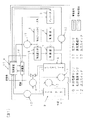
この実施例で示す圧縮機は空気圧縮用のインバータ駆動スクリュー圧縮機である。図1において、Aは制御装置、3はインバータ、4は電動機、5は吸込フィルタ、6は吸込絞り弁、7は圧縮機、8はオイルセパレータ、9はアフタークーラ、10は吐出温度センサ、11は吐出温度センサ、12は圧力スイッチ、13は圧力センサ、14は放気電磁弁、15は始動盤、16は保護器、17は圧力スイッチである。また、実線の矢印は電気信号、破線は空気の流れを示す。
Hereinafter, specific examples of the present invention will be described with reference to these drawings. ◆
The compressor shown in this embodiment is an inverter driven screw compressor for air compression. In FIG. 1, A is a control device, 3 is an inverter, 4 is an electric motor, 5 is a suction filter, 6 is a suction throttle valve, 7 is a compressor, 8 is an oil separator, 9 is an after cooler, 10 is a discharge temperature sensor, 11 Is a discharge temperature sensor, 12 is a pressure switch, 13 is a pressure sensor, 14 is an air release solenoid valve, 15 is a start panel, 16 is a protector, and 17 is a pressure switch. Solid arrows indicate electrical signals, and broken lines indicate air flow.
圧縮機7から吐出された圧縮空気の圧力は圧力センサ13により検出され、始動盤15内の制御装置Aに入力される。制御装置A内に記憶しているP(比例)、I(積分)、D(微分)等の制御動作のための各係数及び目標圧力値を演算式の変数として読み取り、入力された空気圧力値と目標圧力値との偏差から制御量をPID及び複数の演算をする。この複数の演算については後で詳述する。
The pressure of the compressed air discharged from the compressor 7 is detected by the
制御装置Aは故障検出手段である吐出温度センサ10,11、または始動盤15内の保護器16やインバータ3などから入力された故障情報を故障か否か判断し、故障と判断した場合には圧縮機の運転を停止させる。また、制御装置Aはスイッチ類の押/離情報を入力し、それに対する処理を行なう。
The control device A determines whether or not the failure information input from the
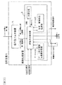
図3に示すように、制御装置Aは、操作部と表示部を備えた装置aと、実際に制御を行なう制御処理装置bの2つから構成され、制御処理装置bは、演算増幅器を中心に抵抗やコンデンサなどの素子で構成したアナログ回路と、CPUやROM、RAMなどのICで構成したデジタル回路を兼ねた制御装置で、制御装置Aの入出力信号は全てアナログ信号として扱われ、制御装置内の演算処理はデジタル信号として扱われる。 As shown in FIG. 3, the control device A is composed of two devices: a device a having an operation unit and a display unit, and a control processing device b that actually performs control. The control processing device b is centered on an operational amplifier. A control device that combines an analog circuit composed of elements such as resistors and capacitors and a digital circuit composed of an IC such as a CPU, ROM, RAM, etc., and all input / output signals of the control device A are treated as analog signals. Arithmetic processing in the apparatus is treated as a digital signal.
PID及び前記複数の演算に係わる圧力検出からインバータ3への電源周波数指令出力までの過程は、圧縮機7の運転中に制御装置Aが常に一定なインターバルで演算処理することにより高い応答性が得られる。
The process from the pressure detection related to the PID and the plurality of calculations to the output of the power supply frequency command to the
制御装置Aは、回転速度制御に係わる吐出圧力検出、PID及びPID等の制御動作のための前記複数の各係数の読み取り、目標圧力値の読み取り、PID及び前記複数の演算、インバータへの指令値出力までの過程をデジタル演算処理を行ない、また故障検知,警報検知,スイッチ類の押/離確認,運転状況把握等の情報入力も行なう。 The control device A detects the discharge pressure related to the rotational speed control, reads the plurality of coefficients for the control operation such as PID and PID, reads the target pressure value, PID and the plurality of calculations, and the command value to the inverter The process up to the output is digitally processed, and information such as failure detection, alarm detection, switch push / release confirmation, and operation status grasp is also input.
インバータ駆動圧縮機に関するPID制御におけるフィードバック制御の基本構成は図6に示す通りで、図中の制御装置内のPID演算を基本とし図2に示すように、吐出圧力検出は電圧信号等のアナログ値で制御装置に入力され、制御装置内でA/D(アナログ/デジタル)変換を行なってデジタル値で演算処理を行ない、さらにD/A(デジタル/アナログ)変換を行なって電圧信号等のアナログ値をインバータへ電源周波数指令出力を行なう。 The basic configuration of the feedback control in the PID control for the inverter driven compressor is as shown in FIG. 6, and based on the PID calculation in the control device in the figure, the discharge pressure is detected as an analog value such as a voltage signal. In the control device, A / D (analog / digital) conversion is performed in the control device to perform arithmetic processing with a digital value, and D / A (digital / analog) conversion is further performed to obtain an analog value such as a voltage signal. The power frequency command is output to the inverter.
また、制御装置Aはデジタル値をデジタル信号として直接出力する機能も有し、制御装置Aからインバータ3への電源周波数指令出力をデジタル値で出力し、インバータ側のデジタル演算制御回路に直接入力も可能な構造となっている。
The control device A also has a function of directly outputting a digital value as a digital signal. The control device A outputs a power frequency instruction output from the control device A to the
以下、図4及び図5を用いて前述した複数の演算について詳細に説明する。◆
アナログPID制御によるインバータ駆動スクリュー圧縮機の制御は、抵抗やコンデンサなどの素子で構成したアナログ回路で行なうため、主にP・I・Dの各回路とその合成回路でしか演算できず、目標圧力値と空気圧力値との偏差Δpから演算した制御量がインバータで必要とする電源周波数指令の上限・下限値を大きく超えてしまう状況があり、この範囲内に指令値が戻るとき、指令値の行き過ぎによる戻りの遅れが出てしまい、応答性に限界があった。
Hereinafter, the plurality of operations described above will be described in detail with reference to FIGS. 4 and 5. ◆
Control of the inverter driven screw compressor by analog PID control is performed by an analog circuit composed of elements such as a resistor and a capacitor. There is a situation where the control amount calculated from the deviation Δp between the air pressure value and the air pressure value greatly exceeds the upper and lower limits of the power frequency command required by the inverter, and when the command value returns within this range, There was a delay in return due to overshoot, and there was a limit to responsiveness.
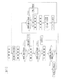
インバータ駆動スクリュー圧縮機で吐出空気圧力Pを一定以内に制御できる使用空気率Aが、定格の30〜100%で、これに対するインバータの電動機への出力電源周波数割合Bが、定格の30〜100%以内の場合、出力電源周波数割合が30〜100%外になるような指令をしてしまう演算結果が出てしまうとき、演算を中止し30〜100%以内に戻るまでそれまでに演算した値を保持することにより、制御の応答性を最大限に速くすることができ、吐出空気圧力の変動幅を最小限にすることができる機能を備えている。P(比例)演算は偏差Δpに対し比例倍するだけであるため応答性への影響はあまり無いが、I(積分)演算は偏差Δpの値を積分しその値を蓄えてしまう。吐出圧力Pが目標圧力値に限り無く近づいて安定した場合偏差Δpは0になる。この場合、P(比例)、D(微分)の値は0になり、I(積分)の値だけが残る。このI(積分)の値の範囲が出力電源周波数割合Bと一致する場合、使用空気率Aが積分の値の割合と同等になる。吐出圧力が目標圧力値から急激に離れ使用空気率Aが変化した後安定した時、積分値が必要以上になり使用空気率Aと同等の割合まで戻るまで時間がかかってしまい、目標圧力値に対しての吐出圧力のオーバーシュートが大きくなってしまう。積分時間を必要以上に短くすると応答性は良くなる反面安定性が悪くなってしまう。積分時間を短くしなくても積分値の範囲を使用空気率A以内にすることにより、応答性、安定性を共に向上することができる。この機能は図4中の積分演算範囲限定(1)でおこなう(詳細説明は後述)。 The operating air rate A that can control the discharge air pressure P within a certain range with an inverter driven screw compressor is 30 to 100% of the rating, and the output power frequency ratio B to the motor of the inverter is 30 to 100% of the rating. If the calculation result that gives a command that causes the output power supply frequency ratio to be outside the range of 30 to 100%, the calculation is stopped and the value calculated so far is returned to within 30 to 100%. By holding, it is possible to maximize the control responsiveness and minimize the fluctuation range of the discharge air pressure. Since the P (proportional) calculation is only proportionally multiplied with respect to the deviation Δp, there is not much influence on the responsiveness, but the I (integral) calculation integrates the value of the deviation Δp and stores the value. When the discharge pressure P becomes close to the target pressure value and stabilizes, the deviation Δp becomes zero. In this case, the values of P (proportional) and D (differential) are 0, and only the value of I (integration) remains. When the range of the value of I (integration) matches the output power supply frequency ratio B, the operating air ratio A is equivalent to the ratio of the integration value. When the discharge pressure suddenly deviates from the target pressure value and stabilizes after the change in the operating air rate A, it takes time for the integrated value to become more than necessary and to return to a rate equivalent to the operating air rate A. On the other hand, the overshoot of the discharge pressure becomes large. If the integration time is shortened more than necessary, the responsiveness is improved, but the stability is deteriorated. Even if the integration time is not shortened, the response value and the stability can be improved by setting the range of the integrated value within the operating air ratio A. This function is performed by limiting the integral calculation range (1) in FIG. 4 (details will be described later).
吐出圧力値pを制御装置Aに入力する場合、またインバータ3への電源周波数指令を制御装置Aから出力する場合、制御装置でそれぞれA/D変換及びD/A変換を行なうが、A/D、D/Aコンバータの入力ビット数は多くない。圧縮機7の回転速度制御をPID制御で行なう場合、安定性、応答性共に良くないと吐出圧力pが目標圧力piから大きく離れたり、ハンチングを繰返したりしてしまうため、積分,微分よりも比例の割合が非常に高くなるように設定されている。A/Dコンバータの入力ビット数が8ビットの場合、分解能1/256以下で入力が変化した場合には、吐出圧力入力0〜10kgf/cm2Gに対して約0.039kgf/cm2変化したことになり、この値を制御装置内で比例演算のみで30倍演算すると、D/Aコンバータの入力ビット数が8ビットの場合、分解能1/256×30倍でインバータへ出力すると、電源周波数指令18〜60Hzに対して約4.9Hz変化してしまう。比例演算の30倍は、インバータ駆動スクリュー圧縮機で使用するPID制御のP(比例演算倍率)の最適値であり、圧縮機を駆動するためのモータの定格出力の違いにより若干差はあるものの、20〜40倍が最適な修正幅である。
When the discharge pressure value p is input to the control device A and when the power supply frequency command to the
吐出圧力pが目標圧力(指示圧力)piから離れるときはインバータ3の電源周波数を急激に変化させた方が応答性は良くなるため、微妙な吐出圧力の変化に対しても電源周波数指令を大きく変化させる。
When the discharge pressure p departs from the target pressure (indicated pressure) pi, the response is better when the power supply frequency of the
しかし、吐出圧力pが目標圧力piに近づく場合は、積分演算値と比例演算値の増減が逆になり、積分,微分演算値の最小変化量と比例演算値の最小変化量の差が大きいため電源周波数指令が歯形の様な出力波形になり、圧縮機や電動機等から異音が発生し、操作員に不安感を与え、インバータトリップ(過電流保護)による停止も起こりやすくなる。また、吐出圧力が目標圧力付近で安定している場合でも、吐出圧力の僅かな変化に対して電源周波数指令が大きく変化してしまうため、吐出圧力及びインバータ電源周波数が脈動してしまう。そこで、本実施例では積分演算と比例演算の増減が逆の場合のみ比例演算を分割して出力し、比例演算と積分演算に不感帯を設けて吐出圧力の目標圧力付近での微妙な変化を無視させることにより、上記の問題を解決している。 However, when the discharge pressure p approaches the target pressure pi, the increase and decrease of the integral calculation value and the proportional calculation value are reversed, and the difference between the minimum change amount of the integral and differential calculation values and the minimum change amount of the proportional calculation value is large. The power supply frequency command becomes an output waveform like a tooth profile, abnormal noise is generated from the compressor, electric motor, etc., giving the operator anxiety, and stopping due to inverter trip (overcurrent protection) is also likely to occur. Further, even when the discharge pressure is stable near the target pressure, the power supply frequency command greatly changes with a slight change in the discharge pressure, so that the discharge pressure and the inverter power supply frequency pulsate. Therefore, in this embodiment, proportional calculation is divided and output only when the increase / decrease of integral calculation and proportional calculation is reversed, and a dead zone is provided for proportional calculation and integral calculation to ignore subtle changes in the vicinity of the target pressure of discharge pressure. This solves the above problem.
PID及び複数の回転速度制御のためのデジタル演算は一定周期(例えば0.1秒周期)で演算するため、積分演算と比例演算の増減が逆の時、比例演算値の変化ΔK/0.1sec.を分割する。10分割すると、1分割につき0.1sec.必要とするため、ΔK/10を1.0sec.にわたり10回カウントすることにより、制御装置の出力精度は一時的に10倍になり、積分,微分演算値の最小変化量と比例演算値の最小変化量の差が大きい場合の問題は解消される。この10分割は、圧縮機から末端の配管までの間の空気が使用される空気配管容量の場合の吐出圧力変化に対する最適値であり、前記空気配管容量が極端に少ない場合は0分割、極端に多い場合は99分割まで設定変更できるように設計されている。また、制御装置Aはこの分割回数を設定し記憶する機能を持ち、吐出圧力の変動状況に応じて最適な設定を行なうことができる。 Since the digital calculation for PID and a plurality of rotational speed control is performed at a constant cycle (for example, 0.1 second cycle), when the increase / decrease of the integral calculation and the proportional calculation is reversed, the change of the proportional calculation value ΔK / 0.1 sec. Split. Since 10 divisions require 0.1 sec. Per division, counting ΔK / 10 10 times over 1.0 sec. Temporarily increases the output accuracy of the control device by a factor of 10 and The problem when the difference between the minimum change amount and the minimum change amount of the proportional calculation value is large is solved. This 10 division is the optimum value for the discharge pressure change in the case of the air pipe capacity in which the air from the compressor to the terminal pipe is used. When the air pipe capacity is extremely small, it is divided into 0, In many cases, it is designed so that the setting can be changed up to 99 divisions. Further, the control device A has a function of setting and storing the number of divisions, and can optimally set according to the fluctuation state of the discharge pressure.
前述した比例演算値の分割処理は、比例,積分演算値の増減が逆で吐出圧力が目標圧力に近づく場合に効果的である。吐出圧力が目標圧力付近で安定している場合でさらに吐出圧力が目標圧力から微妙に離れる時には、比例演算値分割処理は行なわれず、僅かな吐出圧力の変化では電源周波数を変化させないようにして安定性を持たせるている。このため、図4に示すように比例,積分各演算にそれぞれ前記の不感帯±pf、±if、及び微分演算に不感帯±dfを設けている。また、制御装置Aは比例,積分,微分各演算の不感帯の幅を設定し記憶する機能を持つ。この各設定値は同等の値に固定されていても良いが、吐出圧力の変化量により最適な設定値を設定できるようにするとなおよい。 The division process of the proportional calculation value described above is effective when the proportional and integral calculation values increase and decrease and the discharge pressure approaches the target pressure. When the discharge pressure is stable near the target pressure and the discharge pressure deviates slightly from the target pressure, proportional calculation value division processing is not performed, and the power supply frequency is not changed by a slight change in the discharge pressure. Have sex. Therefore, as shown in FIG. 4, the dead zones ± pf and ± if are provided for the proportional and integral operations, and the dead zones ± df are provided for the differential operation. Further, the control device A has a function of setting and storing the dead band width of each of the proportional, integral and derivative operations. Each set value may be fixed to an equivalent value, but it is more preferable that an optimum set value can be set according to the change amount of the discharge pressure.
比例演算値の最小変化量が積分,微分演算値の最小変化量よりも多い場合、比例演算不感帯の幅よりも積分,微分演算不感帯の幅を狭めることにより、吐出圧力が目標圧力付近で微妙な変化をした時に比例演算値を0のまま積分,微分演算のみで目標圧力に対する吐出圧力の補正を行なうことができるので、安定性のよい制御が可能となる。 If the minimum change amount of the proportional calculation value is larger than the minimum change value of the integral / differential calculation value, the discharge pressure becomes subtle near the target pressure by narrowing the width of the integral / differential calculation dead zone rather than the width of the proportional calculation dead zone. When the change is made, it is possible to correct the discharge pressure with respect to the target pressure by only integrating and differentiating with the proportional calculation value kept at 0, so that stable control can be performed.
また、制御装置A内の積分演算にはもう一つの不感帯処理(図4中の積分演算範囲限定(2))を設け、積分演算値がある値以上(上限値)かある値以下(下限値)になったとき、積分演算を行なわずに積分演算値を保持するようにし、この上限,下限値を設定し記憶する。これは積分時間が短い場合、積分演算を行なう範囲を限定することにより、積分演算値の過大または過少による戻りの遅れを最小限に抑えることができる。 Also, another dead band process (integral calculation range limitation (2) in FIG. 4) is provided for the integral calculation in the control device A, and the integral calculation value is greater than a certain value (upper limit value) or less than a certain value (lower limit value). ), The integral calculation value is held without performing the integral calculation, and the upper and lower limits are set and stored. In the case where the integration time is short, by limiting the range in which the integration operation is performed, the return delay due to the excessive or insufficient integration operation value can be minimized.
また、上述したように制御装置A内には積分演算にもう一つの不感帯処理(図4中の積分演算範囲限定(1))が設けられている。これは上述した使用空気率Aが積分の値の割合と同等になると述べたが、実際に使用される空気の使用率が限られる場合、その使用空気率と同等の積分値の割合の幅を設定することにより、前記積分演算範囲限定(2)と同等の効果を持つ。この2つの積分不感帯処理を行なうことにより、より細かな積分不感帯処理を可能とする。 Further, as described above, another dead zone process (integral calculation range limitation (1) in FIG. 4) is provided in the control apparatus A for the integral calculation. It has been stated that the above-mentioned air use rate A is equivalent to the ratio of the integral value. However, when the use rate of the air actually used is limited, the width of the ratio of the integral value equivalent to the use air rate is set. Setting this has the same effect as the integral calculation range limitation (2). By performing these two integral dead-zone processes, finer integral dead-band processes are possible.
(実施例2)◆
次に、本発明の実施例2を説明する。実施例2において実施例1と共通する部分については説明を省略する。◆
制御装置のPID演算及び回転速度制御のための複数のデジタル演算の周期時間を、温度検知等の他の制御を行なうために高速にできない場合、1周期での偏差の変化量が増加し、インバータへの電源周波数指令値の変化量の増加による回転速度制御の乱れが生じる。これに対し本実施例では比例演算値の分割処理を行ない、インバータへの電源周波数指令値の変化量を分割して指令することができようにし、これにより指令値の必要以上の増加を最小限にすることができる。
(Example 2) ◆
Next, a second embodiment of the present invention will be described. In the second embodiment, description of portions common to the first embodiment is omitted. ◆
When the period time of a plurality of digital calculations for PID calculation and rotational speed control of the control device cannot be made high speed to perform other control such as temperature detection, the amount of change in deviation in one period increases, and the inverter The rotational speed control is disturbed due to an increase in the amount of change in the power supply frequency command value. On the other hand, in this embodiment, the division processing of the proportional calculation value is performed so that the change amount of the power supply frequency command value to the inverter can be divided and commanded, thereby minimizing the increase of the command value more than necessary. Can be.
また、インバータ内に、電源周波数指令に対する電源周波数出力への加減速時間を設定できるようにし、制御装置Aからインバータへの電源周波数指令値変化量が多い場合でも、その変化量に対し加減速(積分)を行なうことにより滑らかな電源周波数出力にできるため、安定性の高い回転速度制御が可能となる。 Also, the acceleration / deceleration time for the power supply frequency output with respect to the power supply frequency command can be set in the inverter, and even when the power supply frequency command value change amount from the control device A to the inverter is large, the acceleration / deceleration ( By performing the integration, a smooth power supply frequency output can be obtained, so that a highly stable rotation speed control can be performed.
上記の構成とすることにより、制御装置の演算処理時間を短くできない場合でも高度な回転速度制御が行なえる効果がある。 With the above configuration, there is an effect that advanced rotation speed control can be performed even when the calculation processing time of the control device cannot be shortened.
(実施例3)◆
次に、本発明の実施例3を説明する。実施例3において実施例1,2と共通する部分については説明を省略する。◆
PID及び複数の演算式の各設定値は、吐出圧力や、吐出圧力の変化量と変化時間等の違いにより最適値が決定する。しかし、圧縮機の最大空気吐出量(製品の定格出力)や空気槽の容量等で設定値が変わるため、これらの環境条件に応じて設定値を変えなければならない。
(Example 3) ◆
Next, a third embodiment of the present invention will be described. In the third embodiment, description of portions common to the first and second embodiments is omitted. ◆
The optimum values for the set values of the PID and the plurality of arithmetic expressions are determined depending on the discharge pressure, the amount of change in the discharge pressure, and the change time. However, since the set value changes depending on the maximum air discharge amount (product rated output) of the compressor, the capacity of the air tank, etc., the set value must be changed according to these environmental conditions.
そこで本実施例においては、制御装置Aにおいて、インバータ駆動スクリュー圧縮機を一度運転し、その時の吐出圧力や、吐出圧力の変化量と変化時間等を演算し、この演算結果に基づき最適設定値を求めて記憶しておくことにより、どのような環境条件の変化に対しても最適設定値に自動的に設定することが可能となる。 Therefore, in this embodiment, in the control device A, the inverter-driven screw compressor is operated once, the discharge pressure at that time, the change amount and change time of the discharge pressure, etc. are calculated, and the optimum set value is calculated based on the calculation result. By obtaining and storing the value, it becomes possible to automatically set the optimum setting value for any change in environmental conditions.
また、制御装置Aは、常に吐出圧力や、吐出圧力の変化量と変化時間等を演算するようにし、最適設定値を継続して求めるようにすることにより、被圧縮気体の使用量の変動割合が変わるような場合でも常に最適な制御を行なえるようにできる。 In addition, the control device A always calculates the discharge pressure, the change amount and change time of the discharge pressure, and continuously obtains the optimum set value, thereby changing the rate of change in the amount of compressed gas used. Even when the value changes, optimal control can always be performed.
A…制御装置、B…制御装置、3…インバータ、4…電動機、5…吸込フィルタ、6…吸込絞り弁、7…圧縮機、8…オイルセパレータ、9…アフタークーラ、10…吐出温度センサ、11…吐出温度センサ、12…圧力スイッチ、13…圧力センサ、14…放気電磁弁、15…始動盤、16…保護器、17…圧力スイッチ。
A ... Control device, B ... Control device, 3 ... Inverter, 4 ... Electric motor, 5 ... Suction filter, 6 ... Suction throttle valve, 7 ... Compressor, 8 ... Oil separator, 9 ... After cooler, 10 ... Discharge temperature sensor, DESCRIPTION OF
Claims (14)
前記制御装置は、デジタル計算制御を行うものであって、前記吐出圧力を一定に制御するためのPID演算及びPID演算に対する比例不感帯処理、積分不感帯処理、微分不感帯処理の各演算機能を備えたことを特徴とするインバータ駆動回転型圧縮機。 Compressor, pressure detection means for detecting discharge pressure of gas discharged from the compressor, and control for variable speed control of the rotation speed of the electric motor driving the compressor according to the detected discharge pressure by an inverter Inverter-driven rotary compressor equipped with a device,
The control device performs digital calculation control, and has PID calculation for controlling the discharge pressure to be constant, and a proportional dead band process, an integral dead band process, and a differential dead band process for the PID calculation. An inverter-driven rotary compressor characterized by
前記制御装置は、デジタル計算制御を行うものであって、前記吐出圧力を一定に制御するためのPID演算及びPID演算に対する比例不感帯処理、積分不感帯処理、微分不感帯処理、比例演算分割処理、積分演算範囲限定処理の各演算機能を備え、
吐出量の急激な増減状態時または増減の少ない安定状態時のとき前記各演算を実行して前記吐出圧力の変化を一定以内にすることを特徴とするインバータ駆動回転型圧縮機。 Compressor, pressure detection means for detecting discharge pressure of gas discharged from the compressor, and control for variable speed control of the rotation speed of the electric motor driving the compressor according to the detected discharge pressure by an inverter Inverter-driven rotary compressor equipped with a device,
The control device performs digital calculation control, and controls PID calculation for controlling the discharge pressure to be constant and proportional deadband processing, integral deadband processing, differential deadband processing, differential deadband processing, proportional calculation division processing, and integral calculation for the PID calculation. It has each calculation function of the range limitation process,
An inverter-driven rotary compressor characterized in that, when the discharge amount is suddenly increased or decreased or when the discharge amount is stable and the increase or decrease is small, the calculation is performed to keep the change in the discharge pressure within a certain range.
前記制御装置は、デジタル計算制御により前記吐出圧力を一定に制御するようにPID演算を行なうものであって、P(比例演算)とI(積分演算)の増減が逆の場合には前記比例演算を分割して出力し、かつ前記比例演算と積分演算に不感帯を設けて吐出圧力の目標圧力付近での微妙な圧力変化を無視した制御を行なうことを特徴とするインバータ駆動回転型圧縮機。 A screw compressor that rotates a screw rotor with an electric motor to compress gas, a pressure detector that detects a discharge pressure of the compressed gas, and an inverter that allows the rotation speed of the electric motor to be controlled according to the detected discharge pressure. Inverter-driven rotary compressor provided with a control device that performs shift control,
The control device performs PID calculation so that the discharge pressure is controlled to be constant by digital calculation control, and when the increase (decrease) in P (proportional calculation) and I (integral calculation) is opposite, the proportional calculation is performed. An inverter-driven rotary compressor characterized in that control is performed while ignoring subtle pressure changes near the target pressure of the discharge pressure by providing a dead zone in the proportional calculation and integral calculation.
前記制御装置は、デジタル計算制御により前記吐出圧力を一定に制御するようにPID演算を行なうものであって、吐出圧力が目標圧力付近で安定している場合でかつ吐出圧力が目標圧力から微妙に離れる時、僅かな吐出圧力の変化では電源周波数が変化しないようにP(比例),I(積分)の各演算にそれぞれ不感帯を設けたことを特徴とするインバータ駆動回転型圧縮機。 A screw compressor that rotates a screw rotor with an electric motor to compress gas, a pressure detector that detects a discharge pressure of the compressed gas, and an inverter that allows the rotation speed of the electric motor to be controlled according to the detected discharge pressure. Inverter-driven rotary compressor provided with a control device that performs shift control,
The control device performs PID calculation so that the discharge pressure is controlled to be constant by digital calculation control, and the discharge pressure is subtle from the target pressure when the discharge pressure is stable near the target pressure. An inverter-driven rotary compressor characterized in that a dead zone is provided in each of the P (proportional) and I (integral) calculations so that the power supply frequency does not change with a slight change in discharge pressure when leaving.
前記制御装置は、デジタル計算制御により前記吐出圧力を一定に制御するようにPID演算を行なうものであって、この各PID演算に対しそれぞれP(比例)不感帯、I(積分)不感帯、D(微分)不感帯を設け、かつ前記I(積分)演算にはさらに別の不感帯処理である積分演算範囲限定aを設け、積分演算値が上限値以上または下限値以下となったとき積分演算を行なわず、現状の積分演算値を保持することを特徴とするインバータ駆動回転型圧縮機。 Compressor, pressure detection means for detecting discharge pressure of gas discharged from the compressor, and control for variable speed control of the rotation speed of the electric motor driving the compressor according to the detected discharge pressure by an inverter Inverter-driven rotary compressor equipped with a device,
The control device performs PID calculation so as to control the discharge pressure to be constant by digital calculation control, and for each PID calculation, P (proportional) dead zone, I (integral) dead zone, D (differential) ) A dead band is provided, and the I (integration) calculation is further provided with an integral calculation range limit a which is another dead band process, and when the integral calculation value is equal to or higher than the upper limit value or lower limit value, the integral calculation is not performed. An inverter-driven rotary compressor that retains the current integral calculation value.
前記制御装置はデジタル計算制御により行うものであって、前記吐出圧力を一定に制御する為のPID演算、及びPID演算に対する比例不感帯処理、積分不感帯処理、微分不感帯処理、比例演算分割処理、積分演算範囲限定処理の各演算機能を備え、
前記制御装置へ圧力値入力のためのADコンバータの入力ビット数及び前記制御装置からのインバータへの電源周波数出力のためのDAコンバータの入力ビット数が少ない場合でも、吐出量の急激な増減状態または増減の少ない安定状態に対して、前記各演算を実行することにより演算による制御の遅れを最小限にし、安定した電源周波数指令を制御装置からインバータへ出力し、吐出圧力の変化を一定以内にすることを特徴とするインバータ駆動回転型圧縮機。 A screw compressor having a screw rotor built in the casing and rotating the screw rotor by an electric motor to compress gas; pressure detecting means for detecting a discharge pressure of the compressed gas and outputting the pressure value; and commercial power And an inverter that converts the electric power into electric power of a different frequency, and a control device that controls the rotation speed of the electric motor in a variable speed according to the detected discharge pressure and controls the discharge pressure to be constant by increasing or decreasing the discharge amount. Inverter-driven rotary compressor
The control device performs digital calculation control, and controls PID calculation for controlling the discharge pressure constant, proportional dead band processing for PID calculation, integral dead band processing, differential dead band processing, proportional calculation division processing, integral calculation It has each calculation function of the range limitation process,
Even if the number of input bits of the AD converter for pressure value input to the control device and the number of input bits of the DA converter for power frequency output to the inverter from the control device are small, By executing each of the above calculations for a stable state with little increase / decrease, the control delay due to the calculation is minimized, and a stable power supply frequency command is output from the control device to the inverter to keep the discharge pressure change within a certain range. An inverter-driven rotary compressor characterized by that.
前記制御装置は、8ビットマイコンによるデジタル計算制御を行うものであって、前記吐出圧力を一定に制御するためのPID演算及びPID演算に対する比例不感帯処理、積分不感帯処理、微分不感帯処理、比例演算分割処理、積分演算範囲限定処理の各演算機能を備え、
I(積分)演算は、吐出圧力を一定値以内に制御することができるような使用空気率の範囲以内に、前記積分演算の積分値の割合を抑え、
かつPID演算における比例演算倍率は20〜40倍であり、
さらに、前記吐出圧力が目標圧力から離れる場合には微妙な吐出圧力の変化に対しても電源周波数指令を他の場合に比較し割合として大きく変化させることを特徴とするインバータ駆動回転型圧縮機。 A screw compressor, a pressure detection means for detecting the discharge pressure of the gas discharged from the compressor, and a rotation speed of the electric motor that drives the compressor in accordance with the detected discharge pressure is controlled by an inverter. Inverter-driven rotary compressor equipped with a control device
The control device performs digital calculation control by an 8-bit microcomputer, and performs PID calculation for controlling the discharge pressure to be constant, proportional dead band processing for the PID calculation, integral dead band processing, differential dead band processing, proportional calculation division Each function of processing, integration calculation range limitation processing,
In the I (integration) calculation, the ratio of the integral value of the integral calculation is suppressed within the range of the operating air rate such that the discharge pressure can be controlled within a certain value,
And the proportional calculation magnification in PID calculation is 20 to 40 times,
Further, when the discharge pressure deviates from the target pressure, the inverter-driven rotary compressor is characterized in that the power supply frequency command is largely changed as a ratio even in a subtle change in the discharge pressure as compared with other cases.
Priority Applications (1)
| Application Number | Priority Date | Filing Date | Title |
|---|---|---|---|
| JP2007206039A JP2007285307A (en) | 2007-08-08 | 2007-08-08 | Inverter-drive rotary compressor |
Applications Claiming Priority (1)
| Application Number | Priority Date | Filing Date | Title |
|---|---|---|---|
| JP2007206039A JP2007285307A (en) | 2007-08-08 | 2007-08-08 | Inverter-drive rotary compressor |
Related Parent Applications (1)
| Application Number | Title | Priority Date | Filing Date |
|---|---|---|---|
| JP06248796A Division JP4031842B2 (en) | 1996-03-19 | 1996-03-19 | Inverter-driven rotary compressor |
Publications (2)
| Publication Number | Publication Date |
|---|---|
| JP2007285307A true JP2007285307A (en) | 2007-11-01 |
| JP2007285307A5 JP2007285307A5 (en) | 2007-12-20 |
Family
ID=38757296
Family Applications (1)
| Application Number | Title | Priority Date | Filing Date |
|---|---|---|---|
| JP2007206039A Pending JP2007285307A (en) | 2007-08-08 | 2007-08-08 | Inverter-drive rotary compressor |
Country Status (1)
| Country | Link |
|---|---|
| JP (1) | JP2007285307A (en) |
Cited By (3)
| Publication number | Priority date | Publication date | Assignee | Title |
|---|---|---|---|---|
| WO2015082432A1 (en) * | 2013-12-05 | 2015-06-11 | Knorr-Bremse Systeme für Schienenfahrzeuge GmbH | Compressor system for a rail vehicle and method for operating the compressor system with safe emergency operation |
| WO2015082430A1 (en) * | 2013-12-05 | 2015-06-11 | Knorr-Bremse Systeme für Schienenfahrzeuge GmbH | Compressor system and method for operating the compressor system in dependence on the operating state of the rail vehicle |
| CN106609754A (en) * | 2015-07-24 | 2017-05-03 | 池州汉诺威机电设备科技有限公司 | Screw rod air compressor frequency conversion control system |
Citations (5)
| Publication number | Priority date | Publication date | Assignee | Title |
|---|---|---|---|---|
| JPH04501A (en) * | 1990-04-17 | 1992-01-06 | Toshiba Corp | Process controller |
| JPH06156299A (en) * | 1992-11-27 | 1994-06-03 | Aisin Seiki Co Ltd | Automated auxiliary steering device of vehicle |
| JPH0720904A (en) * | 1993-07-05 | 1995-01-24 | Toshiba Corp | Limiter setting device of process controller |
| JPH0735079A (en) * | 1993-07-27 | 1995-02-03 | Hitachi Ltd | Packaged screw compressor |
| JPH07286584A (en) * | 1994-04-19 | 1995-10-31 | Hitachi Ltd | Inverter-driven screw compressor |
-
2007
- 2007-08-08 JP JP2007206039A patent/JP2007285307A/en active Pending
Patent Citations (5)
| Publication number | Priority date | Publication date | Assignee | Title |
|---|---|---|---|---|
| JPH04501A (en) * | 1990-04-17 | 1992-01-06 | Toshiba Corp | Process controller |
| JPH06156299A (en) * | 1992-11-27 | 1994-06-03 | Aisin Seiki Co Ltd | Automated auxiliary steering device of vehicle |
| JPH0720904A (en) * | 1993-07-05 | 1995-01-24 | Toshiba Corp | Limiter setting device of process controller |
| JPH0735079A (en) * | 1993-07-27 | 1995-02-03 | Hitachi Ltd | Packaged screw compressor |
| JPH07286584A (en) * | 1994-04-19 | 1995-10-31 | Hitachi Ltd | Inverter-driven screw compressor |
Cited By (10)
| Publication number | Priority date | Publication date | Assignee | Title |
|---|---|---|---|---|
| WO2015082432A1 (en) * | 2013-12-05 | 2015-06-11 | Knorr-Bremse Systeme für Schienenfahrzeuge GmbH | Compressor system for a rail vehicle and method for operating the compressor system with safe emergency operation |
| WO2015082430A1 (en) * | 2013-12-05 | 2015-06-11 | Knorr-Bremse Systeme für Schienenfahrzeuge GmbH | Compressor system and method for operating the compressor system in dependence on the operating state of the rail vehicle |
| CN105934583A (en) * | 2013-12-05 | 2016-09-07 | 克诺尔轨道车辆系统有限公司 | Compressor system and method for operating the compressor system in dependence on the operating state of the rail vehicle |
| CN105940221A (en) * | 2013-12-05 | 2016-09-14 | 克诺尔轨道车辆系统有限公司 | A compressor system for a rail vehicle and method for operating the compressor system with safe emergency operation |
| AU2014359381B2 (en) * | 2013-12-05 | 2017-09-14 | Knorr-Bremse Systeme Fur Schienenfahrzeuge Gmbh | Compressor system for a rail vehicle and method for operating the compressor system with safe emergency operation |
| AU2014359379B2 (en) * | 2013-12-05 | 2017-09-28 | Knorr-Bremse Systeme Fur Schienenfahrzeuge Gmbh | Compressor system and method for operating the compressor system in dependence on the operating state of the rail vehicle |
| RU2638231C1 (en) * | 2013-12-05 | 2017-12-12 | Кнорр-Бремзе Зюстеме Фюр Шиненфарцойге Гмбх | Compressor system and method of compressor system operation depending on rail vehicle operation mode |
| RU2646988C2 (en) * | 2013-12-05 | 2018-03-13 | Кнорр-Бремзе Зюстеме Фюр Шиненфарцойге Гмбх | Compressor system for a rail vehicle and method of a compressor system operation with emergency speed safe mode |
| US10207695B2 (en) * | 2013-12-05 | 2019-02-19 | Knorr-Bremse Systeme Fur Schienenfahrzeuge Gmbh | Compressor system and method for operating the compressor system in dependence on the operating state of the rail vehicle |
| CN106609754A (en) * | 2015-07-24 | 2017-05-03 | 池州汉诺威机电设备科技有限公司 | Screw rod air compressor frequency conversion control system |
Similar Documents
| Publication | Publication Date | Title |
|---|---|---|
| US8278864B2 (en) | Compressor control | |
| US9903378B2 (en) | Method of operating a pumping system | |
| JP4031842B2 (en) | Inverter-driven rotary compressor | |
| JP5337662B2 (en) | Apparatus and method for operating hydraulic pump in hydraulic system | |
| JP2008019746A (en) | Compressed-air production facility | |
| US7999502B2 (en) | Pumping system | |
| US8264176B2 (en) | Fan arrangement | |
| WO2006114843A1 (en) | Servo motor controller | |
| JP2013108357A (en) | Compression apparatus | |
| JP2007285307A (en) | Inverter-drive rotary compressor | |
| JP4685715B2 (en) | Power system stabilization method and power system stabilization system using the method | |
| TWI477345B (en) | Coolant system for machine tools | |
| WO2021084821A1 (en) | Compressor, monitoring system, and method of monitoring compressor | |
| CN112283086B (en) | Method for controlling a motor-driven pump in a fluid system | |
| JPH07286584A (en) | Inverter-driven screw compressor | |
| JP2004263631A (en) | Screw compressor and method for operating the same | |
| US20180367082A1 (en) | Vacuum pump drive with star-delta switchover | |
| KR20130028451A (en) | Control apparatus for hydraulic system | |
| EP2529119A1 (en) | Compressor control method and system | |
| JP2001333589A (en) | Overload state detector for motor | |
| JP5111064B2 (en) | Compressor | |
| JPH0851793A (en) | Protection of inverter | |
| JP2004046763A (en) | Automatic controller using computer | |
| JPS62284908A (en) | Helper driving device for turbine | |
| JPS6325198B2 (en) |
Legal Events
| Date | Code | Title | Description |
|---|---|---|---|
| A521 | Written amendment |
Effective date: 20070808 Free format text: JAPANESE INTERMEDIATE CODE: A523 |
|
| A521 | Written amendment |
Free format text: JAPANESE INTERMEDIATE CODE: A523 Effective date: 20070907 |
|
| A621 | Written request for application examination |
Effective date: 20070907 Free format text: JAPANESE INTERMEDIATE CODE: A621 |
|
| A521 | Written amendment |
Free format text: JAPANESE INTERMEDIATE CODE: A523 Effective date: 20070907 |
|
| A977 | Report on retrieval |
Effective date: 20100610 Free format text: JAPANESE INTERMEDIATE CODE: A971007 |
|
| A131 | Notification of reasons for refusal |
Free format text: JAPANESE INTERMEDIATE CODE: A131 Effective date: 20100615 |
|
| A521 | Written amendment |
Effective date: 20100809 Free format text: JAPANESE INTERMEDIATE CODE: A523 |
|
| A02 | Decision of refusal |
Effective date: 20100824 Free format text: JAPANESE INTERMEDIATE CODE: A02 |