JP2007282933A - Method and apparatus for finishing clothes having edge part free from trimming - Google Patents
Method and apparatus for finishing clothes having edge part free from trimming Download PDFInfo
- Publication number
- JP2007282933A JP2007282933A JP2006115123A JP2006115123A JP2007282933A JP 2007282933 A JP2007282933 A JP 2007282933A JP 2006115123 A JP2006115123 A JP 2006115123A JP 2006115123 A JP2006115123 A JP 2006115123A JP 2007282933 A JP2007282933 A JP 2007282933A
- Authority
- JP
- Japan
- Prior art keywords
- finishing
- fabric
- pressing
- hem
- mold
- Prior art date
- Legal status (The legal status is an assumption and is not a legal conclusion. Google has not performed a legal analysis and makes no representation as to the accuracy of the status listed.)
- Granted
Links
- 238000000034 method Methods 0.000 title claims abstract description 8
- 238000009966 trimming Methods 0.000 title abstract 2
- 239000004744 fabric Substances 0.000 claims abstract description 153
- 238000003825 pressing Methods 0.000 claims abstract description 51
- 239000000463 material Substances 0.000 claims description 26
- 238000009415 formwork Methods 0.000 claims description 25
- XAGFODPZIPBFFR-UHFFFAOYSA-N aluminium Chemical compound [Al] XAGFODPZIPBFFR-UHFFFAOYSA-N 0.000 claims description 6
- 229910052782 aluminium Inorganic materials 0.000 claims description 5
- 229920000742 Cotton Polymers 0.000 claims description 3
- 239000002131 composite material Substances 0.000 claims description 3
- 238000004140 cleaning Methods 0.000 claims 3
- 229920001971 elastomer Polymers 0.000 abstract 2
- 239000000806 elastomer Substances 0.000 abstract 2
- 230000037303 wrinkles Effects 0.000 description 8
- 229910052751 metal Inorganic materials 0.000 description 6
- 239000002184 metal Substances 0.000 description 6
- 238000005520 cutting process Methods 0.000 description 4
- 238000001035 drying Methods 0.000 description 4
- 239000000675 fabric finishing Substances 0.000 description 4
- 238000009962 finishing (textile) Methods 0.000 description 4
- 239000000835 fiber Substances 0.000 description 3
- 238000009940 knitting Methods 0.000 description 3
- 238000004519 manufacturing process Methods 0.000 description 3
- 229920002635 polyurethane Polymers 0.000 description 3
- 239000004814 polyurethane Substances 0.000 description 3
- 230000006835 compression Effects 0.000 description 2
- 238000007906 compression Methods 0.000 description 2
- 238000003795 desorption Methods 0.000 description 2
- 230000006866 deterioration Effects 0.000 description 2
- 238000009998 heat setting Methods 0.000 description 2
- 238000010438 heat treatment Methods 0.000 description 2
- 229920000728 polyester Polymers 0.000 description 2
- 239000012209 synthetic fiber Substances 0.000 description 2
- 229920002994 synthetic fiber Polymers 0.000 description 2
- 239000000853 adhesive Substances 0.000 description 1
- 230000001070 adhesive effect Effects 0.000 description 1
- 230000005540 biological transmission Effects 0.000 description 1
- 238000006073 displacement reaction Methods 0.000 description 1
- 238000004043 dyeing Methods 0.000 description 1
- 210000004177 elastic tissue Anatomy 0.000 description 1
- 238000007730 finishing process Methods 0.000 description 1
- 230000001788 irregular Effects 0.000 description 1
- 230000000379 polymerizing effect Effects 0.000 description 1
- 238000009991 scouring Methods 0.000 description 1
- 238000003466 welding Methods 0.000 description 1
- 239000002759 woven fabric Substances 0.000 description 1
Images


Landscapes
- Treatment Of Fiber Materials (AREA)
Abstract
Description
本発明は、後始末不要な縁部を有する筒状の身頃用生地を適宜の仕上げ用型枠に被せて熱セットする際、裾部の生地歪みや皺などの発生を未然に防止するようにした衣類の仕上げ方法並びに装置に関する。 The present invention prevents the occurrence of fabric distortion and wrinkles at the hem when a cylindrical body material having an unnecessary edge is placed on an appropriate finishing form and heat-set. The present invention relates to a method and apparatus for finishing garments.
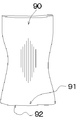
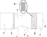
従来、後始末不要な縁部を有する筒状の身頃用生地(成形筒状編生地)90を適宜の仕上げ用型枠を用いて熱セットする際、身頃用生地90がフリーの状態で熱セットされるために、生地が熱収縮現象を生じ、図2の如く、特に直線状の裾部91の生地端縁92が、凹凸状に変形して生地歪みが発生し、しかも裾部91の締め付け感がなくなる恐れがあった。また仕上げ用型枠が、アルミニュウムの金属板で形成されているために、高温に曝された金属板に身頃用生地90が、直接接触すると、後始末不要な縁部、即ち身頃用生地90に編み込まれているポリウレタンなどの伸縮性に富んだ弾性糸が、熱により変質して生地の品質劣化を招き、裾部91の伸縮性が低下する欠点があった。
Conventionally, when a tubular body fabric 90 (molded tubular knitted fabric) 90 having an edge that does not need to be cleaned is heat-set using an appropriate finishing formwork, the
尚、上記後始末不要な身頃用生地の製造法は、従来周知の方法で行なわれるもので、具体的には、先ず筒状成形丸編機により筒状生地を編成する際、例えばポリエステル系繊維などの合成繊維とポリウレタン系弾性繊維などの熱融着性糸条を適宜に交編若しくは引揃えて編成し、適宜の精練、染色加工などを施した後、更に湿熱または乾熱による熱処理を介して該熱融着性糸を該熱融着糸以外の糸に溶着させ、長尺の筒状成形編地全体に解れ止め加工を施すのである。更に長尺の筒状成形編生地を適宜の長さ毎に裁断することにより、身頃用の生地が得られ、同身頃用生地をどの位置においても、或いはどの部位で裁断しても編糸が解れることがないので、格別の解れ防止策を講じる必要がなく、衣服の製造を容易に行うことができるようにしてある。尚、上記身頃用生地の上辺部を適宜裁断して衿部や袖付部を形成して、肌着などの適宜の衣服を製造することができるのである。 The manufacturing method for the body material that is unnecessary to clean up is performed by a conventionally known method. Specifically, when a tubular fabric is first knitted by a tubular forming circular knitting machine, for example, a polyester fiber Synthetic fibers such as polyurethane elastic yarns such as polyurethane-based elastic fibers are appropriately knitted or aligned and subjected to appropriate scouring and dyeing processes, followed by heat treatment with wet heat or dry heat. Then, the heat-fusible yarn is welded to a yarn other than the heat-welding yarn, and the entire long tubular molded knitted fabric is subjected to unwinding processing. Further, by cutting a long cylindrical shaped knitted fabric into appropriate lengths, a body material can be obtained. The knitting yarn can be obtained by cutting the body material at any position or at any part. Since it cannot be unraveled, it is not necessary to take any special measures to prevent unraveling, and clothing can be easily manufactured. In addition, an appropriate garment such as an underwear can be manufactured by appropriately cutting the upper side portion of the body fabric to form a heel portion and a sleeve-attached portion.
解決しようとする問題点は、前記の如く、後始末不要な縁部を有する身頃用生地を仕上げ用型枠に被せて熱セットする際、身頃生地がフリーの状態におかれ、且つ熱セット時に身頃用生地には束縛ないしは緊張感が付与されないために、身頃用生地が加熱室内で自由に熱収縮現象を生じ、特に直線状の裾部側端縁においては、大きな生地歪みを招き、生地の伸縮性低下や品質低下を招く欠点がある。また仕上げ用型枠が、アルミニュウム等の金属板で形成されているので、熱セット時に身頃用生地が、高温の金属板に直接接触するために、ポリウレタン系弾性繊維などの熱融着性糸条が、劣化若しくは脆化して強伸度が低下し、且つ裾部側端縁が、伸び切りの状態になってフィット性が低下し、衣服類としての機能性低下を招き、品質の改善が十分になされていない点にある。 The problem to be solved is that, as described above, when the body fabric having an unnecessary edge is placed on the finishing form and heat-set, the body fabric is left in a free state and the heat-set Since the fabric for the body is not bound or tensioned, the fabric for the body is freely heat-shrinkable in the heating chamber, particularly at the edge of the straight hem side, causing a large fabric distortion, There is a drawback that causes a reduction in stretchability and quality. In addition, since the finishing form is made of a metal plate such as aluminum, the body fabric is in direct contact with the hot metal plate during heat setting. However, deterioration or embrittlement causes a decrease in the strength and elongation, and the hem side edge is in a fully stretched state, resulting in a decrease in fit, resulting in a decrease in functionality as clothing, and a sufficient improvement in quality. There is a point that has not been made.
本発明では、仕上げ用型枠の下方部位に裾部係止用弾性体を設け、且つ同型枠全体に筒状生地を被覆して同生地上に身頃用生地を被せると共に、身頃用生地の裾部を前記裾部係止用弾性体の位置で係止し、更に裾部側被覆用筒状生地を身頃用生地の裾部上に被せ、一方、押圧用型枠を仕上げ用型枠の表裏面側に夫々回動、押圧自在に設けて仕上げ用型枠の表裏面を押圧可能とすると共に、同押圧用型枠の下方部位に押圧用弾性体を設け、同押圧用弾性体を介して裾部側被覆用筒状生地を押圧するようにしたことにより、身頃用生地を束縛ないしは緊張下の状態で熱セットすることができ、従って裾部側端縁に従来のような皺や生地歪みを生じることがなくなるのである。また仕上げ用型枠に筒状生地を被覆したことにより、身頃用生地に編込んである熱融着性糸が、型枠の高温により、劣化若しくは脆化することがなく、伸縮性などに優れた衣服を得ることができるものである。 In the present invention, an elastic body for locking the hem portion is provided at a lower part of the finishing formwork, and the entire formwork is covered with a tubular cloth so that the cloth for the body is covered on the cloth, and the hem of the cloth for the body The hem portion is locked at the position of the elastic body for hem portion locking, and the tubular fabric for covering the hem portion side is placed on the hem portion of the garment body fabric, while the pressing mold is placed on the surface of the finishing mold. It is provided on the back side so that it can be rotated and pressed freely, and the front and back surfaces of the finishing mold can be pressed, and a pressing elastic body is provided below the pressing mold, and the pressing elastic body is interposed therebetween. By pressing the cylindrical fabric for covering the hem side, the garment fabric can be heat-set in a restrained or tensioned state, so the hem side edge can be worn with conventional wrinkles and fabric distortion. Will not occur. In addition, by covering the finishing formwork with a cylindrical fabric, the heat-fusible yarn knitted into the bodywork fabric does not deteriorate or become brittle due to the high temperature of the formwork, and has excellent stretchability. You can get the clothes you want.
本発明では、仕上げ用型枠の下方部位に裾部係止用弾性体を設け、且つ同型枠全体に筒状生地を被覆して同生地上に身頃用生地を被せると共に、裾部の端縁部を前記裾部係止用弾性体の位置で係止し、更に裾部側被覆用筒状生地を身頃用生地の裾部上に被せ、一方、押圧用型枠を仕上げ用型枠の表裏面側に夫々回動、押圧自在に設けて仕上げ用型枠の表裏面側を押圧可能にすると共に、同押圧用型枠の下方部位に押圧用弾性体を設け、同押圧用弾性体を介して裾部側被覆用筒状生地を押圧することにより、身頃用生地の裾部側を束縛ないしは緊張下の状態で熱セットすることができ、また仕上げ用型枠に係止用筒状生地を被覆したことにより、身頃用生地が同型枠側に直接接触することがないので、融着性糸が、型枠の高温により、劣化若しくは脆化することがなくなり、品質の向上が図られるのである。 In the present invention, the bottom part of the finishing formwork is provided with an elastic body for locking the bottom part, and the entire same formwork is covered with the tubular cloth so that the body cloth is covered on the cloth, and the edge of the bottom part The hem portion is locked at the position of the elastic body for hem portion locking, and the tubular fabric for covering the hem portion side is placed on the hem portion of the garment body fabric, while the pressing mold is placed on the surface of the finishing mold. It is provided on the back side so that it can be rotated and pressed freely, so that the front and back sides of the finishing mold can be pressed, and a pressing elastic body is provided in the lower part of the pressing mold, and the pressing elastic body is interposed therebetween. By pressing the hem side covering tubular fabric, the skirt side of the body fabric can be heat-set in a restrained or under tension state, and the locking tubular fabric is attached to the finishing formwork. By covering, the fabric for the body does not come into direct contact with the same formwork side, so the fusible yarn may deteriorate due to the high temperature of the formwork. We prevent that is brittle, is the improvement in quality is achieved.
本発明は、身頃用生地を緊張下で、且つ安定化した状態で熱セットすることにより、裾部側端縁に従来のような皺や生地歪みを生じることがなくなり、また仕上げ用型枠に筒状生地を被覆したことにより、高温の型枠に身頃用生地が直接接触することがなくなり、従って、熱融着性糸が劣化若しくは脆化することがなく、伸縮性など品質に優れた身頃用生地を得ることができるのである。 In the present invention, the garment fabric is heat-set under tension and in a stable state, so that the hem side edge does not cause wrinkles or fabric distortion as in the prior art. By covering the cylindrical fabric, the garment fabric does not come into direct contact with the hot formwork, so the heat-fusible yarn does not deteriorate or become brittle, and the garment has excellent quality such as stretchability. The dough can be obtained.
本発明は、後始末不要な身頃用生地を適宜の仕上げ用型枠を用いて仕上げ加工し、皺が発生せず、伸縮性など品質の優れた身頃用生地が得られるようにしたもので、以下図例に基づいて説明する。 The present invention is to finish a body fabric that is unnecessary for finishing using an appropriate finishing formwork, so that wrinkles do not occur, and a body fabric with excellent quality such as stretchability can be obtained. This will be described below with reference to the drawings.
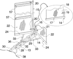
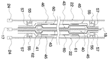
図3において、13は移動用フレームで、適宜の楕円状に設けた図示略のレール上を走行可能とし、且つ従来周知のチェンや伝動歯車などを介して移動、走行自在に設けてあり、14,15,16は、夫々同フレーム13に固定した支軸で、同支軸14には支持片17を回動自在に設けると共に、同支持片17に仕上げ用型枠18を固定してあり、19は支軸14に回動自在に設けた回動片で、同片に仕上げ用型枠18を固定してあり、且つ同型枠18自体は、常にフリーの状態で、回動自在となっている。
In FIG. 3,
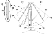
20,21は夫々支軸15,16に回動自在に設けた回動片で、同回動片20,21に夫々押圧用型枠22、22を固定してあり、24、24は夫々押圧用型枠22、22の下端部に固定した支持片である。28、29は夫々前記移動用フレーム13上に固定した固定片で、同固定片28、29間にスライド軸30を摺動自在に設けてある。32は同スライド軸30に固定した固定子で、同固定子32の左右側には、ロッド33、33を回動自在に連結してあり、更に同ロッド33、33を夫々押圧用型枠22、22の下方端部に固定した支持片24、24側に夫々回動自在に連結してある。36は引張り用バネで固定片28と固定子32間に連結、固定してあり、38は従来周知の固定カムで、引張り用バネ36を介してスライド軸30の先端部を固定カム38側に接圧するようにしてあり、且つスライド軸30の前後動により、ロッド33、33を介して押圧用型枠22、22を図4の如く、夫々位置X−Y、X−Y間で開閉回動自在となるようにしてあり、更に押圧用型枠22、22の中間に位置する仕上げ用型枠18は、同押圧用型枠22、22により、表裏面から押圧されるようにしてある。
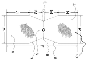
図5において、仕上げ用型枠18は、アルミニウムなどの金属性板で形成されており、4は同型枠18の上側部位、5は胴側部位で、6、7は夫々凹状側辺部,8は凹状側辺部6,7間における垂線部位、9は裾側部位である。尚、仕上げ用型枠18の形状寸法として、実施例では、型枠18の全長Fが980mm、厚みが3mm、上側部位4及び裾側部位9の幅Pが夫々370mm、上側部位4の側辺の長さNが270mm、胴側部位5の凹状側辺部6,7における夫々の側辺の垂線の長さM、Mは190mm、凹状側辺部6,7間における側辺の長さLは20mm、側辺部8−8間の巾Qは230mm、裾側部位における側辺の長さJが310mmとなっている。
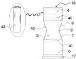
In FIG. 5, the
図6、図11において、仕上げ用型枠18の表裏面側において、上側部位4並びに胴側部位5の夫々の下方部位に、凸状の上辺部係止用弾性体40及び裾部係止用弾性体41を夫々接着、固定してあり、身頃用生地60の上辺部61並びに裾部62を夫々同弾性体40、41側に確実に係止して身頃用生地60の緊張、安定化を図り、仕上げセット時の生地の熱収縮による皺や生地歪みの発生を未然に防止するもので、特に身頃用生地60の上辺部61や裾部62の端縁部の生地歪みなどを防止するようにしてある。尚、前記弾性体40、41の素材の実施例としては、例えばダブルラッセル編機により、ポリエステル系繊維などの合成繊維を適宜用いて編成した従来周知の三層構造による多層生地を複数枚重合し、且つ接着剤などを介して加熱圧着して得られた立体的な多層複合生地42が好ましく、また多層複合生地42の圧縮率の実施例として、例えば150g/cm2荷重時の圧縮率が、15〜25%の範囲が、上辺部及び裾部係止用弾性体40、41用として好適な範囲である。
6 and 11, on the front and back sides of the
また仕上げ用型枠18の表裏面側において、図6、図11の如く、上側部位4における下半分側の位置に凸状の上辺部係止用弾性体40を接着、固定してあり、且つ同弾性体40の形状の実施例としては、厚さが10mm、幅が型枠18の幅よりも若干狭くて320mm、縦方向の長さが40mm以上のものを用いるようにしている。更に仕上げ用型枠18の胴側部位5において下方側位置、即ち凹状側辺部7、7の裾部係止用弾性体41を接着、固定したもので、また同弾性体41の形状としては、厚さが10mm、生地幅が型枠18の幅よりも若干狭くて320mm、縦方向の長さが20mmのものを用いるようにしている。
Further, on the front and back sides of the
図7において、凸状の上辺部並びに裾部係止用弾性体40、41を夫々表裏面側に接着、固定してある仕上げ用型枠18に筒状生地43を全面に被覆するようにしたもので、同筒状生地43の素材としては、筒状の織物地や編物地が好ましく、特に綿糸100%による筒状メリヤス生地のように高温に対して耐久性があり、且つ生地表面が耐摩擦性に優れ、毛羽立っている素材が好ましいのである。また図8において、筒状の身頃用生地60を仕上げ用型枠18に被せ、且つ筒状生地43表面に重合、被覆する際、重合された身頃用生地60と毛羽だった筒状生地43の両者が完全に密着して固定化、安定化され、仕上げセット時に身頃用生地60の上辺部61や裾部62の端縁部63における皺発生や生地歪みが完全に防止できるのである。
In FIG. 7, the upper and lower convex
また前記の如く、身頃用生地60の上辺部61側と裾部62側が、夫々凸状の上辺部及び裾部係止用弾性体40、41の位置で確実に係止されるようにしたことにより、身頃用生地60の緊張、安定化が図られ、更に身頃生地60と筒状生地43の両者が完全に密着して固定化、安定化されるので、仕上げセット時の身頃用生地60の上辺部61や裾部62の端縁部63における皺発生や生地歪みなどの発生が、未然に防止されるのである。尚、身頃用生地60を製品化する際に、同上辺部61を適当に裁断して襟部や袖部を構成し、適宜の衣服を製造する場合もあり、上辺部61の裁断方法は、製品化の目的によって異なるのである。
Further, as described above, the
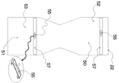
図10において、押圧用型枠22は、アルミニウム製などの金属板により構成されており、且つ同枠22の形状及び寸法は、前記仕上げ用型枠18と同様の構造で構成されており、更に前記仕上げ用型枠18の表裏面側を左右の押圧用型枠22、22で押圧するようにしている。50、51は、夫々押圧用型枠22の上方部位並びに下方部位を示したもので、同上方部位50における上方側位置52並びに下方部位51における上方側位置53の夫々の部位において、固着片55、55を夫々固定してある。尚、同固着片55、55は、その両端縁部を内側に折り曲げた状態に形成してあり、且つ同片55、55の上面側には、前記の弾性体40、41と同様の素材で形成した押圧用弾性体57、57を夫々接着、固定するようにしてある。また固着片55の構成として、実施例では、厚さ3mmのアルミニウムなどの金属板を両端部で折り曲げて、幅が370mm、長さが40mm、高さが25mmからなる折曲げ片で形成するようにしてある。
In FIG. 10, the
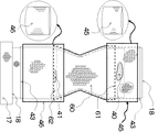
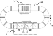
また図9、図11において、身頃用生地60の表面に更に筒状の上部側被覆用筒状生地45を被覆、重合するにあたり、筒状生地43の上方端縁部近辺から上辺部係止用弾性体40の下方端縁部付近の部位にかけて、上部側被覆用筒状生地45を被覆するようにしてある。即ち身頃用生地60の上方端縁部付近に同被覆用筒状生地45を被覆し、身頃用生地60の上辺部61の生地ズレや汚れなどを防止するようにしたものである。更に裾部側被覆用筒状生地46を身頃用生地60の裾部62側に被覆、重合するにあたり、身頃用生地60の裾部62の部位から筒状生地43の下方位置にかけて、裾部側被覆用筒状生地46を被覆し、身頃用生地60の裾部62の生地ズレや汚れなどを防止するようにしたものである。更に身頃用生地60の連続的な生地仕上げを行う手段としては、例えば図12の如き蒸気セット仕上げ装置80の概略装置において、移動用フレーム13を適宜に走行或いは停止させながら、生地仕上げを行うのである。尚、図12において、Aは身頃用生地60の脱着作業区域で、Bは蒸気セット室、Cは乾燥室で、身頃用生地60の脱着作業から蒸気セット及び乾燥を連続的に行うようにしたものである。
Further, in FIGS. 9 and 11, when the cylindrical upper side covering
次いで身頃用生地60を仕上げ用型枠18に被せて生地仕上げをする手段について述べると、先ず図8、図11の如く、表裏面に上辺部並びに裾部係止用弾性体40、41を夫々有する仕上げ用型枠18全体に綿糸などの適宜の繊維で編成した筒状編地による筒状生地43を被覆した状態で、身頃用生地60を仕上げ用型枠18に被せるもので、具体的には、身頃用生地60の上方端縁部61を上辺部係止用弾性体40の部位に位置させると共に、身頃用生地60の裾部端縁部63を裾部係止用弾性体41の部位に位置させるのである。
Next, a means for finishing the cloth by covering the
次いで図9、図11の如く、身頃用生地60の上辺部61及び裾部63側に更に上部側及び裾部側被覆用筒状生地45、46を夫々被覆、重合するにあたり、筒状生地43の上方端縁部付近から上辺部係止用弾性体40の下方端縁部の位置にかけて、上部側被覆用筒状生地45を身頃用生地60の上辺部61近辺に被覆するのである。更に裾部側被覆用筒状生地46を裾部係止用弾性体41の上方位置、即ち身頃用生地60の裾部62近辺の部位から筒状生地43の下方端縁部の位置にかけて被覆するもので、このようにして身頃用生地60の裾部62近辺を同被覆用筒状生地46により被覆するのである。
Next, as shown in FIGS. 9 and 11, the
次いで図4、図11及び図12の如く、脱着作業区域Aにおいて、仕上げ用型枠18の表裏面側で、押圧用型枠22,22を押圧する、即ち、図4の如く、押圧用型枠22,22を夫々位置Yから位置Xの部位まで回動させ、同枠22、22を夫々仕上げ用型枠18の表裏面側に圧着して身頃用生地60を圧着保持するのである。即ち押圧用型枠22に設けた上方位置にある押圧用弾性体57を上辺部係止用弾性体40の部位よりも上方位置で、即ち身頃用生地60の上辺部61よりも上方の位置で上辺部被覆用筒状生地45を圧着保持するのである。更に押圧用型枠22に設けた下方位置にある押圧用弾性体57を裾部係止用弾性体41の部位よりも下方の位置で、即ち身頃用生地60の裾部62よりも下方の位置で裾部側被覆用筒状生地46を圧着保持するもので、このようにして上辺部並びに裾部側被覆用筒状生地45、46を圧着保持することにより、熱セット仕上げ時に、同被覆用筒状生地45、46を介して身頃用生地60が確実に圧着保持されて熱セットされるのである。尚、身頃用生地60の上辺部61及び裾部62は、夫々前記被覆用筒状生地45、46により、完全に被覆されるので、汚れや皺などの発生が防止されるのである。
Next, as shown in FIG. 4, FIG. 11 and FIG. 12, in the attachment / detachment work area A, the
次いで移動用フレーム13を公知の手段で移送しながら、仕上げ用型枠18及び押圧用型枠22,22間で圧着、保持された身頃用生地60を蒸気セット室Bの位置まで搬送して蒸気セットを行い、次いで乾燥室Cにおいて、身頃用生地60の乾燥を行い、更に脱着作業区域Aに達すると、押圧用型枠22,22を夫々元の位置Xから位置Yの部位まで回動され、同型枠22、22が、夫々仕上げ用型枠18から離反するのである。
Next, while the moving
即ち、脱着作業がし易いように同型枠22、22を押し拡げ、この状態で、仕上げ用型枠18に装着され、熱セット仕上げされた身頃用生地60を同型枠18から取り外すのである。次いで熱セット用の新たな身頃用生地60を仕上げ用型枠18に装着し、次いで押圧用型枠22,22を位置Yから元の位置Xの部位まで回動させて、仕上げ用型枠18の表裏面側に押圧用型枠22,22を押圧し、この状態で移動用フレーム13を公知の手段で移送し、前記の如く、蒸気セット室B、乾燥室Cの各工程で連続的に生地仕上げ処理が施されるのである。また蒸気セットによる生地仕上げを行うにあたり、蒸気セット温度としては115〜125℃の範囲が好ましく、また蒸気セット時間は30〜90秒の範囲が好ましいのである。
That is, the
尚、押圧用型枠22に設けた下方部の押圧用弾性体57を裾部係止用弾性体41の部位と同じ部位に位置させる、即ち身頃用生地60の裾部62近辺に前記押圧用弾性体57を位置させ、同弾性体57を介して裾部側被覆用筒状生地46及び身頃用生地60の裾部62を押圧するようにしてもよいのである。従って身頃用生地60の裾部62を圧着保持することにより、同裾部62の汚れや皺などの発生を防止できるのである。
The lower pressing
身頃用生地60の上辺部61及び裾部62付近を上部側及び裾部側被覆用筒状生地45、46介して夫々被覆するようにしてあるが、上部側及び裾部側被覆用筒状生地45、46の分割された2枚の生地の代わりに1枚生地で構成するようにしてもよいのである。
The
18 仕上げ用型枠
22 押圧用型枠
40 上辺部係止用弾性体
41 裾部係止用弾性体
57 押圧用弾性体
43 筒状生地
45 上部側被覆用筒状生地
46 裾部側被覆用筒状生地
60 身頃用生地
18 Finishing
Claims (6)
Priority Applications (1)
| Application Number | Priority Date | Filing Date | Title |
|---|---|---|---|
| JP2006115123A JP4895665B2 (en) | 2006-04-19 | 2006-04-19 | Finishing method and apparatus for clothing having unnecessary edge |
Applications Claiming Priority (1)
| Application Number | Priority Date | Filing Date | Title |
|---|---|---|---|
| JP2006115123A JP4895665B2 (en) | 2006-04-19 | 2006-04-19 | Finishing method and apparatus for clothing having unnecessary edge |
Publications (2)
| Publication Number | Publication Date |
|---|---|
| JP2007282933A true JP2007282933A (en) | 2007-11-01 |
| JP4895665B2 JP4895665B2 (en) | 2012-03-14 |
Family
ID=38755230
Family Applications (1)
| Application Number | Title | Priority Date | Filing Date |
|---|---|---|---|
| JP2006115123A Expired - Fee Related JP4895665B2 (en) | 2006-04-19 | 2006-04-19 | Finishing method and apparatus for clothing having unnecessary edge |
Country Status (1)
| Country | Link |
|---|---|
| JP (1) | JP4895665B2 (en) |
Citations (4)
| Publication number | Priority date | Publication date | Assignee | Title |
|---|---|---|---|---|
| JPS63286193A (en) * | 1987-05-19 | 1988-11-22 | 富士車輌株式会社 | Undershirt presser |
| JPH0397947U (en) * | 1990-01-25 | 1991-10-09 | ||
| JPH0747196A (en) * | 1993-05-04 | 1995-02-21 | Macpi Spa | Ironing equipment |
| JP2000185200A (en) * | 1998-12-22 | 2000-07-04 | Tokyo Sensen Kikai Seisakusho:Kk | Garment press |
-
2006
- 2006-04-19 JP JP2006115123A patent/JP4895665B2/en not_active Expired - Fee Related
Patent Citations (4)
| Publication number | Priority date | Publication date | Assignee | Title |
|---|---|---|---|---|
| JPS63286193A (en) * | 1987-05-19 | 1988-11-22 | 富士車輌株式会社 | Undershirt presser |
| JPH0397947U (en) * | 1990-01-25 | 1991-10-09 | ||
| JPH0747196A (en) * | 1993-05-04 | 1995-02-21 | Macpi Spa | Ironing equipment |
| JP2000185200A (en) * | 1998-12-22 | 2000-07-04 | Tokyo Sensen Kikai Seisakusho:Kk | Garment press |
Also Published As
| Publication number | Publication date |
|---|---|
| JP4895665B2 (en) | 2012-03-14 |
Similar Documents
| Publication | Publication Date | Title |
|---|---|---|
| JP5711862B2 (en) | Industrial fabric containing spirally wound strip material | |
| RU2015124800A (en) | TECHNICAL FABRIC AND METHOD FOR WELDING THE SEAM AREA USING ULTRASONIC WELDING | |
| HK1040889A1 (en) | Method of forming irregularities on cloth of garment and garment | |
| KR20140001064A (en) | Fabric stack structure and clothes, bedding | |
| ES2691076T3 (en) | Industrial fabric that includes spirally wound material strips with reinforcement | |
| JP2012218437A (en) | Three-dimensional shaped textile element and method of manufacturing the same | |
| KR101029327B1 (en) | Manufacturing method of double-sided raised fabric having piles on both sides of fabric and double-sided raised fabric having double-sided pile manufactured thereby | |
| JP4895665B2 (en) | Finishing method and apparatus for clothing having unnecessary edge | |
| GB2175026A (en) | Contractile non-woven interlinings and process for their manufacture | |
| JP4355524B2 (en) | Felt for papermaking | |
| JP2000345417A (en) | Method of forming irregularities on clothes fabric | |
| CN113040457B (en) | Assembled textile product | |
| JP3194799U (en) | Triple structure fabric | |
| FI20190036A1 (en) | Mop cloth and floor maintenance device | |
| TWI428487B (en) | Elastic silicone rubber belt and method of manufacturing the same | |
| JP2018024956A (en) | Layering knitted fabric composite, manufacturing method therefor, and body mounting fixture using the layering knitted fabric composite | |
| JP2005154145A5 (en) | ||
| TWI626346B (en) | Belt or sleeve for use in nonwoven production and method for forming the same | |
| KR101795314B1 (en) | A Method for Producing a Elastic Seamless Fabric Eco-Friendly | |
| PT1941092E (en) | A needled belt with high thickness and elasticity | |
| KR20110033371A (en) | Quilt using Meriya's fabric and its manufacturing method | |
| JP3845793B2 (en) | Fabric product forming method with surface thermoforming part from fabric | |
| KR101451773B1 (en) | The folds of the fabric laminate molding method and the resulting fabric wrinkles | |
| JP2006219766A (en) | Continuously knitted knit fabric and unit clothes produced from the same fabric and method for producing the same | |
| JP2007137993A (en) | Heat-resistant transport belt and method for producing the same |
Legal Events
| Date | Code | Title | Description |
|---|---|---|---|
| A621 | Written request for application examination |
Free format text: JAPANESE INTERMEDIATE CODE: A621 Effective date: 20090401 |
|
| A977 | Report on retrieval |
Free format text: JAPANESE INTERMEDIATE CODE: A971007 Effective date: 20110224 |
|
| A131 | Notification of reasons for refusal |
Free format text: JAPANESE INTERMEDIATE CODE: A131 Effective date: 20110412 |
|
| A521 | Written amendment |
Free format text: JAPANESE INTERMEDIATE CODE: A523 Effective date: 20110607 |
|
| RD03 | Notification of appointment of power of attorney |
Free format text: JAPANESE INTERMEDIATE CODE: A7423 Effective date: 20110607 |
|
| TRDD | Decision of grant or rejection written | ||
| A01 | Written decision to grant a patent or to grant a registration (utility model) |
Free format text: JAPANESE INTERMEDIATE CODE: A01 Effective date: 20111220 |
|
| A01 | Written decision to grant a patent or to grant a registration (utility model) |
Free format text: JAPANESE INTERMEDIATE CODE: A01 |
|
| A61 | First payment of annual fees (during grant procedure) |
Free format text: JAPANESE INTERMEDIATE CODE: A61 Effective date: 20111220 |
|
| R150 | Certificate of patent (=grant) or registration of utility model |
Free format text: JAPANESE INTERMEDIATE CODE: R150 |
|
| FPAY | Renewal fee payment (prs date is renewal date of database) |
Free format text: PAYMENT UNTIL: 20150106 Year of fee payment: 3 |
|
| FPAY | Renewal fee payment (prs date is renewal date of database) |
Free format text: PAYMENT UNTIL: 20150106 Year of fee payment: 3 |
|
| LAPS | Cancellation because of no payment of annual fees |