JP2007282918A - Individual package and manufacturing method thereof - Google Patents
Individual package and manufacturing method thereof Download PDFInfo
- Publication number
- JP2007282918A JP2007282918A JP2006114809A JP2006114809A JP2007282918A JP 2007282918 A JP2007282918 A JP 2007282918A JP 2006114809 A JP2006114809 A JP 2006114809A JP 2006114809 A JP2006114809 A JP 2006114809A JP 2007282918 A JP2007282918 A JP 2007282918A
- Authority
- JP
- Japan
- Prior art keywords
- applicator
- packaging
- sheet
- substantially flat
- opening
- Prior art date
- Legal status (The legal status is an assumption and is not a legal conclusion. Google has not performed a legal analysis and makes no representation as to the accuracy of the status listed.)
- Granted
Links
- 238000004519 manufacturing process Methods 0.000 title claims description 35
- 230000002745 absorbent Effects 0.000 claims abstract description 25
- 239000002250 absorbent Substances 0.000 claims abstract description 25
- 238000004806 packaging method and process Methods 0.000 claims description 164
- 238000005304 joining Methods 0.000 claims description 30
- 238000000034 method Methods 0.000 claims description 13
- 238000003780 insertion Methods 0.000 claims description 10
- 230000037431 insertion Effects 0.000 claims description 10
- 239000005022 packaging material Substances 0.000 description 29
- 238000004049 embossing Methods 0.000 description 26
- 239000011295 pitch Substances 0.000 description 16
- 238000003860 storage Methods 0.000 description 15
- 238000012360 testing method Methods 0.000 description 14
- 238000007789 sealing Methods 0.000 description 11
- 239000004698 Polyethylene Substances 0.000 description 10
- 239000000853 adhesive Substances 0.000 description 10
- 230000001070 adhesive effect Effects 0.000 description 10
- 238000005520 cutting process Methods 0.000 description 10
- -1 polypropylene Polymers 0.000 description 8
- 239000006096 absorbing agent Substances 0.000 description 7
- 239000004743 Polypropylene Substances 0.000 description 6
- 238000005452 bending Methods 0.000 description 6
- 229920001155 polypropylene Polymers 0.000 description 6
- 238000012545 processing Methods 0.000 description 6
- 210000001124 body fluid Anatomy 0.000 description 5
- 230000000052 comparative effect Effects 0.000 description 5
- 238000011156 evaluation Methods 0.000 description 5
- 229920000573 polyethylene Polymers 0.000 description 5
- 230000003746 surface roughness Effects 0.000 description 5
- 239000000463 material Substances 0.000 description 4
- 239000010839 body fluid Substances 0.000 description 3
- 239000012943 hotmelt Substances 0.000 description 3
- 239000004745 nonwoven fabric Substances 0.000 description 3
- 229920005989 resin Polymers 0.000 description 3
- 239000011347 resin Substances 0.000 description 3
- 238000011282 treatment Methods 0.000 description 3
- 210000001215 vagina Anatomy 0.000 description 3
- 239000008280 blood Substances 0.000 description 2
- 210000004369 blood Anatomy 0.000 description 2
- 238000004364 calculation method Methods 0.000 description 2
- 229920001903 high density polyethylene Polymers 0.000 description 2
- 239000004700 high-density polyethylene Substances 0.000 description 2
- 239000005001 laminate film Substances 0.000 description 2
- 229920001684 low density polyethylene Polymers 0.000 description 2
- 239000004702 low-density polyethylene Substances 0.000 description 2
- 239000003550 marker Substances 0.000 description 2
- 230000002175 menstrual effect Effects 0.000 description 2
- 230000001953 sensory effect Effects 0.000 description 2
- 229920000742 Cotton Polymers 0.000 description 1
- 229920010126 Linear Low Density Polyethylene (LLDPE) Polymers 0.000 description 1
- 229920000297 Rayon Polymers 0.000 description 1
- XUIMIQQOPSSXEZ-UHFFFAOYSA-N Silicon Chemical compound [Si] XUIMIQQOPSSXEZ-UHFFFAOYSA-N 0.000 description 1
- BZHJMEDXRYGGRV-UHFFFAOYSA-N Vinyl chloride Chemical compound ClC=C BZHJMEDXRYGGRV-UHFFFAOYSA-N 0.000 description 1
- 238000010521 absorption reaction Methods 0.000 description 1
- 230000015572 biosynthetic process Effects 0.000 description 1
- 238000003851 corona treatment Methods 0.000 description 1
- 238000010586 diagram Methods 0.000 description 1
- 239000000835 fiber Substances 0.000 description 1
- 230000004927 fusion Effects 0.000 description 1
- 238000010438 heat treatment Methods 0.000 description 1
- 238000009776 industrial production Methods 0.000 description 1
- 239000010410 layer Substances 0.000 description 1
- 238000002844 melting Methods 0.000 description 1
- 230000008018 melting Effects 0.000 description 1
- 230000005906 menstruation Effects 0.000 description 1
- 238000007719 peel strength test Methods 0.000 description 1
- 239000002964 rayon Substances 0.000 description 1
- 230000001105 regulatory effect Effects 0.000 description 1
- 230000035807 sensation Effects 0.000 description 1
- 229910052710 silicon Inorganic materials 0.000 description 1
- 239000010703 silicon Substances 0.000 description 1
- 239000002356 single layer Substances 0.000 description 1
- 238000005507 spraying Methods 0.000 description 1
- 229920003002 synthetic resin Polymers 0.000 description 1
- 239000000057 synthetic resin Substances 0.000 description 1
- 229920001169 thermoplastic Polymers 0.000 description 1
- 229920005992 thermoplastic resin Polymers 0.000 description 1
- 239000004416 thermosoftening plastic Substances 0.000 description 1
Images


Classifications
-
- A—HUMAN NECESSITIES
- A61—MEDICAL OR VETERINARY SCIENCE; HYGIENE
- A61F—FILTERS IMPLANTABLE INTO BLOOD VESSELS; PROSTHESES; DEVICES PROVIDING PATENCY TO, OR PREVENTING COLLAPSING OF, TUBULAR STRUCTURES OF THE BODY, e.g. STENTS; ORTHOPAEDIC, NURSING OR CONTRACEPTIVE DEVICES; FOMENTATION; TREATMENT OR PROTECTION OF EYES OR EARS; BANDAGES, DRESSINGS OR ABSORBENT PADS; FIRST-AID KITS
- A61F13/00—Bandages or dressings; Absorbent pads
- A61F13/15—Absorbent pads, e.g. sanitary towels, swabs or tampons for external or internal application to the body; Supporting or fastening means therefor; Tampon applicators
- A61F13/20—Tampons, e.g. catamenial tampons; Accessories therefor
-
- A—HUMAN NECESSITIES
- A61—MEDICAL OR VETERINARY SCIENCE; HYGIENE
- A61F—FILTERS IMPLANTABLE INTO BLOOD VESSELS; PROSTHESES; DEVICES PROVIDING PATENCY TO, OR PREVENTING COLLAPSING OF, TUBULAR STRUCTURES OF THE BODY, e.g. STENTS; ORTHOPAEDIC, NURSING OR CONTRACEPTIVE DEVICES; FOMENTATION; TREATMENT OR PROTECTION OF EYES OR EARS; BANDAGES, DRESSINGS OR ABSORBENT PADS; FIRST-AID KITS
- A61F13/00—Bandages or dressings; Absorbent pads
- A61F13/15—Absorbent pads, e.g. sanitary towels, swabs or tampons for external or internal application to the body; Supporting or fastening means therefor; Tampon applicators
- A61F13/551—Packaging before or after use
- A61F13/55175—Packaging before or after use packaging of tampons
-
- A—HUMAN NECESSITIES
- A61—MEDICAL OR VETERINARY SCIENCE; HYGIENE
- A61F—FILTERS IMPLANTABLE INTO BLOOD VESSELS; PROSTHESES; DEVICES PROVIDING PATENCY TO, OR PREVENTING COLLAPSING OF, TUBULAR STRUCTURES OF THE BODY, e.g. STENTS; ORTHOPAEDIC, NURSING OR CONTRACEPTIVE DEVICES; FOMENTATION; TREATMENT OR PROTECTION OF EYES OR EARS; BANDAGES, DRESSINGS OR ABSORBENT PADS; FIRST-AID KITS
- A61F13/00—Bandages or dressings; Absorbent pads
- A61F13/15—Absorbent pads, e.g. sanitary towels, swabs or tampons for external or internal application to the body; Supporting or fastening means therefor; Tampon applicators
- A61F13/551—Packaging before or after use
- A61F13/55175—Packaging before or after use packaging of tampons
- A61F13/5518—Packaging before or after use packaging of tampons after use
-
- A—HUMAN NECESSITIES
- A61—MEDICAL OR VETERINARY SCIENCE; HYGIENE
- A61F—FILTERS IMPLANTABLE INTO BLOOD VESSELS; PROSTHESES; DEVICES PROVIDING PATENCY TO, OR PREVENTING COLLAPSING OF, TUBULAR STRUCTURES OF THE BODY, e.g. STENTS; ORTHOPAEDIC, NURSING OR CONTRACEPTIVE DEVICES; FOMENTATION; TREATMENT OR PROTECTION OF EYES OR EARS; BANDAGES, DRESSINGS OR ABSORBENT PADS; FIRST-AID KITS
- A61F13/00—Bandages or dressings; Absorbent pads
- A61F13/15—Absorbent pads, e.g. sanitary towels, swabs or tampons for external or internal application to the body; Supporting or fastening means therefor; Tampon applicators
- A61F13/551—Packaging before or after use
- A61F13/55175—Packaging before or after use packaging of tampons
- A61F13/55185—Packaging before or after use packaging of tampons in combination with the applicator
-
- A—HUMAN NECESSITIES
- A61—MEDICAL OR VETERINARY SCIENCE; HYGIENE
- A61F—FILTERS IMPLANTABLE INTO BLOOD VESSELS; PROSTHESES; DEVICES PROVIDING PATENCY TO, OR PREVENTING COLLAPSING OF, TUBULAR STRUCTURES OF THE BODY, e.g. STENTS; ORTHOPAEDIC, NURSING OR CONTRACEPTIVE DEVICES; FOMENTATION; TREATMENT OR PROTECTION OF EYES OR EARS; BANDAGES, DRESSINGS OR ABSORBENT PADS; FIRST-AID KITS
- A61F15/00—Auxiliary appliances for wound dressings; Dispensing containers for dressings or bandages
- A61F15/001—Packages or dispensers for bandages, cotton balls, drapes, dressings, gauze, gowns, sheets, sponges, swabsticks or towels
- A61F15/003—Packages or dispensers for bandages, cotton balls, drapes, dressings, gauze, gowns, sheets, sponges, swabsticks or towels dispensers for catamenial tampons
-
- B—PERFORMING OPERATIONS; TRANSPORTING
- B65—CONVEYING; PACKING; STORING; HANDLING THIN OR FILAMENTARY MATERIAL
- B65D—CONTAINERS FOR STORAGE OR TRANSPORT OF ARTICLES OR MATERIALS, e.g. BAGS, BARRELS, BOTTLES, BOXES, CANS, CARTONS, CRATES, DRUMS, JARS, TANKS, HOPPERS, FORWARDING CONTAINERS; ACCESSORIES, CLOSURES, OR FITTINGS THEREFOR; PACKAGING ELEMENTS; PACKAGES
- B65D75/00—Packages comprising articles or materials partially or wholly enclosed in strips, sheets, blanks, tubes or webs of flexible sheet material, e.g. in folded wrappers
- B65D75/04—Articles or materials wholly enclosed in single sheets or wrapper blanks
-
- B—PERFORMING OPERATIONS; TRANSPORTING
- B65—CONVEYING; PACKING; STORING; HANDLING THIN OR FILAMENTARY MATERIAL
- B65D—CONTAINERS FOR STORAGE OR TRANSPORT OF ARTICLES OR MATERIALS, e.g. BAGS, BARRELS, BOTTLES, BOXES, CANS, CARTONS, CRATES, DRUMS, JARS, TANKS, HOPPERS, FORWARDING CONTAINERS; ACCESSORIES, CLOSURES, OR FITTINGS THEREFOR; PACKAGING ELEMENTS; PACKAGES
- B65D75/00—Packages comprising articles or materials partially or wholly enclosed in strips, sheets, blanks, tubes or webs of flexible sheet material, e.g. in folded wrappers
- B65D75/52—Details
- B65D75/58—Opening or contents-removing devices added or incorporated during package manufacture
- B65D75/5827—Tear-lines provided in a wall portion
Landscapes
- Health & Medical Sciences (AREA)
- Engineering & Computer Science (AREA)
- General Health & Medical Sciences (AREA)
- Public Health (AREA)
- Heart & Thoracic Surgery (AREA)
- Vascular Medicine (AREA)
- Life Sciences & Earth Sciences (AREA)
- Animal Behavior & Ethology (AREA)
- Veterinary Medicine (AREA)
- Biomedical Technology (AREA)
- Epidemiology (AREA)
- Mechanical Engineering (AREA)
- Absorbent Articles And Supports Therefor (AREA)
- Packages (AREA)
- Containers And Plastic Fillers For Packaging (AREA)
- Bag Frames (AREA)
- Packaging Of Annular Or Rod-Shaped Articles, Wearing Apparel, Cassettes, Or The Like (AREA)
Abstract
【課題】アプリケータ付タンポンの取り扱いを容易にした個包装体を提供する。
【解決手段】個包装体は、外筒及び内筒を有するアプリケータとこのアプリケータから押し出し可能に収納される吸収体とからなるタンポンと、所定のシート状部材により形成される略縦長状の略扁平袋体と、を備える。略扁平袋体は、略扁平状における一方側にタンポンを取り出し可能に形成される開封部と、略扁平袋体の長手方向に開閉可能な蓋部と、を備える。そして、蓋部は、開封部を覆うように設けられる。
【選択図】図1An object of the present invention is to provide an individual package that facilitates handling of a tampon with an applicator.
An individual wrapping body has a substantially vertically long shape formed by a tampon comprising an applicator having an outer cylinder and an inner cylinder, and an absorbent body that can be pushed out from the applicator, and a predetermined sheet-like member. A substantially flat bag body. The substantially flat bag body includes an opening portion formed so that the tampon can be taken out on one side of the substantially flat shape, and a lid portion that can be opened and closed in the longitudinal direction of the substantially flat bag body. And a cover part is provided so that an opening part may be covered.
[Selection] Figure 1
Description
本発明は、個包装体およびその製造方法に関する。特に、アプリケータ付のタンポンを個別に収容する個包装体およびその製造方法に関する。 The present invention relates to an individual package and a manufacturing method thereof. In particular, the present invention relates to an individual package that individually accommodates tampon with an applicator and a method for manufacturing the same.
従来より、生理中の女性が膣腔内に挿入して使用する吸収性物品として、体液等を吸収する吸収体と、この吸収体の後端部に設けられる紐と、を備える、いわゆる生理用タンポンが広く知られている。このような生理用タンポンには、アプリケータの内部に収納しておき、このアプリケータを用いて吸収体を体内に挿入するものと、アプリケータを用いずに指で吸収体を体内に挿入するものとがある。例えば、アプリケータを用いた生理用タンポンは、吸収体が収納されたアプリケータを膣腔内の所定の位置まで挿入し、アプリケータから吸収体を押出すことにより、吸収体をより確実に膣腔奥部へ挿入することを可能としている。(例えば、特許文献1)。
しかしながら、特許文献1に開示された生理用タンポンに用いられるアプリケータは、前述したように直接体内に挿入して使用されるため、使用後は経血等の体液が表面に付着した状態となり処理に困るという問題を有していた。
However, since the applicator used in the sanitary tampon disclosed in
特に、使用済みのアプリケータを開封済みの包装袋に戻して処分しようとする場合、従来の包装袋は、包装袋の長手方向の両側における一方側のみをシールした形状を有し、一端部に設けられた切り欠き状の切れ目から包装袋を長手方向に切り裂くことにより開封するため、開封時における開封口の大きさ等が安定せず、アプリケータを戻しにくいという問題があった。また、上記切れ目から包装袋の一部が分離し、余計なごみを出してしまうおそれもあった。さらには、包装袋の長手方向における両側をシールすることにより、包装袋を形成した場合においては、フィルム同士が貼りつきやすく、間口をうまく開くことができないという問題を有していた。そして、これらが本発明の課題といってよい。 In particular, when the used applicator is to be returned to the opened packaging bag for disposal, the conventional packaging bag has a shape in which only one side on both sides in the longitudinal direction of the packaging bag is sealed, Since the packaging bag is opened by tearing in the longitudinal direction from the cut-out cut provided, there is a problem that the size of the opening at the time of opening is not stable and the applicator is difficult to return. In addition, a part of the packaging bag is separated from the cut, and there is a possibility that extra garbage is taken out. Furthermore, when the packaging bag is formed by sealing both sides in the longitudinal direction of the packaging bag, there is a problem that the films are easily stuck to each other and the frontage cannot be opened well. And these may be the subject of the present invention.
本発明は、以上のような課題に鑑みてなされたものであり、アプリケータ付タンポンの取り扱いを容易にした個包装体を提供することを目的とする。 This invention is made | formed in view of the above subjects, and it aims at providing the individual package which made easy handling of the tampon with an applicator.
本発明者らは、上記目的を達成するため、両側部の一部をシールした略扁平袋の内部表面に凹凸加工を施し、開封部に長手方向に開閉可能な蓋部を設けることにより、開口形状の安定した間口が得られることを見出し、本発明を完成するに至った。具体的には、本発明は以下のような個包装体およびその製造方法を提供する。 In order to achieve the above-mentioned object, the present inventors perform uneven processing on the inner surface of a substantially flat bag with a part of both sides sealed, and provide a lid that can be opened and closed in the longitudinal direction at the opening. The inventors have found that a frontage with a stable shape can be obtained, and have completed the present invention. Specifically, the present invention provides the following individual package and a method for producing the same.
(1) 外筒及び内筒を有するアプリケータと、前記アプリケータから押し出し可能に収納される吸収体と、を備えるタンポンが、所定のシート状部材により形成される略縦長状の略扁平袋体に個別に封入される個包装体であって、前記略扁平袋体は、略扁平状における一方側に形成され、前記タンポンを取り出し可能に形成される開封部と、前記一方側に設けられ、前記略扁平袋体の長手方向に開閉可能な蓋部と、を備え、前記開封部は、前記蓋部に覆われてなる個包装体。 (1) A substantially vertically long, substantially flat bag body in which a tampon including an outer cylinder and an applicator having an inner cylinder and an absorbent body that can be pushed out from the applicator is formed by a predetermined sheet-like member. The substantially flat bag body is formed on one side of the substantially flat shape, and is provided on the one side with an opening portion formed so that the tampon can be taken out, A lid portion that can be opened and closed in a longitudinal direction of the substantially flat bag body, and the opening portion is covered with the lid portion.
(1)の発明によれば、個包装体は、外筒及び内筒を有するアプリケータとこのアプリケータから押し出し可能に収納される吸収体とからなるタンポンと、所定のシート状部材により形成される略縦長状の略扁平袋体と、を備える。略扁平袋体は、略扁平状における一方側にタンポンを取り出し可能に形成される開封部と、略扁平袋体の長手方向に開閉可能な蓋部と、を備える。そして、蓋部は、開封部を覆うように設けられる。なお、略扁平袋体とは、伸長時におけるアプリケータの長さの少なくとも1/3以上の長さを包むことが可能なものを含む。 According to the invention of (1), the individual wrapping body is formed by a tampon including an applicator having an outer cylinder and an inner cylinder, and an absorbent body that can be pushed out from the applicator, and a predetermined sheet-like member. A substantially vertically long, substantially flat bag body. The substantially flat bag body includes an opening portion formed so that the tampon can be taken out on one side of the substantially flat shape, and a lid portion that can be opened and closed in the longitudinal direction of the substantially flat bag body. And a cover part is provided so that an opening part may be covered. In addition, a substantially flat bag body contains what can wrap the length of at least 1/3 or more of the length of the applicator at the time of expansion | extension.
このように、略扁平袋体の略扁平状における一方側にタンポンを取り出し可能に形成される開封部と、略扁平袋体の長手方向に開閉可能な蓋部と、を設けることにより、開封部において、開口形状の安定した間口を得ることが可能になる。また、開封部を蓋部が覆う構成とするため、開封部において蓋部が隆起し、開封部の位置が分り易くなる。また、例えば、開封部の形状を山形に形成した場合においては、開封部における間口が広がりやすくなり、使用済みのアプリケータが入れやすくなる。また、蓋部を設けたことにより、使用済みのアプリケータを収納した後に、蓋をすることが可能となるため、開封後の略扁平袋体を清潔に保つことが可能になる。さらに、例えば、蓋部に再接着が可能な接着手段を用いて接着させておくことにより、開封後においても再度蓋部を接着することが可能になり、開封後の略扁平状袋体を清潔に保つことができる。 Thus, by providing the opening part formed so that the tampon can be taken out on one side in the substantially flat shape of the substantially flat bag body, and the lid part that can be opened and closed in the longitudinal direction of the substantially flat bag body, the opening part In this case, it is possible to obtain a frontage having a stable opening shape. Moreover, since it is set as the structure which a cover part covers an opening part, a cover part protrudes in an opening part and it becomes easy to understand the position of an opening part. In addition, for example, when the shape of the opening portion is formed in a mountain shape, the front opening in the opening portion is likely to spread, and a used applicator can be easily placed. Further, since the lid portion is provided, it is possible to cover the used applicator after the used applicator is accommodated, so that the substantially flat bag body after opening can be kept clean. Furthermore, for example, by adhering to the lid using an adhesive means capable of re-adhesion, the lid can be adhered again even after opening, and the substantially flat bag body after opening is cleaned. Can be kept in.
なお、所定のシート状部材とは、例えば、熱可塑性の軟質フィルムが挙げられるが、本発明においてはこれに限らず、例えば、生分解性フィルム、不織布、ラミネートフィルム、和紙等の単体又はこれらを組み合わせたものも用いることができる。軟質フィルムを使用した場合においては、例えば、携帯時及び開封時において、フィルム同士が擦れて生じる不快な音を減少させることが可能になり、触感も向上させることができる。 The predetermined sheet-like member includes, for example, a thermoplastic flexible film, but is not limited to this in the present invention, for example, a biodegradable film, a nonwoven fabric, a laminate film, a Japanese paper or the like alone or these Combinations can also be used. When a soft film is used, for example, it is possible to reduce unpleasant noise caused by rubbing between the films when carrying and opening, and the tactile sensation can also be improved.
(2) 前記蓋部は、前記開封部と連続して形成されており、該開封部は、前記蓋部と切り離し可能なミシン目状に形成されてなる(1)に記載の個包装体。 (2) The individual packaging body according to (1), wherein the lid portion is formed continuously with the opening portion, and the opening portion is formed in a perforated shape that is separable from the lid portion.
(2)の発明によれば、開封部は、蓋部と連続して形成されると共に、蓋部と切り離し可能なミシン目状に形成される。これにより、開封部の開封が蓋部の長手方向に向かう開封操作によるものとなる。また、ミシン目状の開封部は常時蓋部で覆われており、ミシン目を破るまで開封部の間口は開かないため、略扁平袋体に封入されているタンポンが直接外気に触れる事がなくなり、清潔に保つことができる。 According to the invention of (2), the opening portion is formed continuously with the lid portion and is formed in a perforated shape that can be separated from the lid portion. Thereby, opening of an opening part becomes by opening operation which goes to the longitudinal direction of a cover part. In addition, the perforated opening is always covered with a lid, and the opening of the opening does not open until the perforation is broken, so that the tampon enclosed in the flat bag body does not directly touch the outside air. Can be kept clean.
(3) 前記蓋部は、該蓋部と一体に形成された把持部を有する(1)または(2)に記載の個包装体。 (3) The individual packaging body according to (1) or (2), wherein the lid portion includes a grip portion formed integrally with the lid portion.
(3)の発明によれば、蓋部は、この蓋部と一体に形成された把持部を有する。これにより、開封時において、把持部を用いて開封することが可能になるため、略扁平袋体の開封が容易になる。ここで、一体に形成されるとは、例えば、蓋部の一部を把持部として使用することを含む。また、把持部は、蓋部を形成するシート状部材を折り返して形成してもよい。このように折り返して把持部を形成することにより、把持部が隆起し、立体的に形成されるため、さらに開封部を容易に知ることが可能となる。 According to the invention of (3), the lid portion has a grip portion formed integrally with the lid portion. Thereby, since it becomes possible to open using a holding part at the time of opening, opening of a substantially flat bag body becomes easy. Here, being integrally formed includes, for example, using a part of the lid part as a grip part. The gripping part may be formed by folding back a sheet-like member that forms the lid part. By forming the grip portion by folding back in this way, the grip portion rises and is formed in a three-dimensional manner, so that it is possible to easily know the opening portion.
(4) 前記略扁平袋体は、内面に凹凸加工が施されてなる(1)から(3)のいずれか記載の個包装体。 (4) The said substantially flat bag body is an individual package body in any one of (1) to (3) by which uneven | corrugated processing is given to the inner surface.
(4)の発明によれば、略扁平袋体は、アプリケータ付タンポンが収容される収納部の内面側を形成する面に凹凸加工、例えば、エンボス加工が施されている。これにより、略扁平袋体を形成するシート状部材同士の接触面積が減り、シート状部材同士が貼り付きにくくなると同時に、はがれ易くなる。また、シート状部材の表面に凹凸が存在することで、シート状部材の剛軟度に差異、すなわち、比較的軟らかな部分と比較的剛質な部分が生じる。これにより、軟らかな部分が剛質な部分から力を受けることによりシール状部材が曲がり易くなる。したがって、略扁平袋体の開封が容易になると共に、開封時において所定の空間部を形成し易くなる。 According to invention of (4), as for the substantially flat bag body, uneven | corrugated processing, for example, embossing, is given to the surface which forms the inner surface side of the accommodating part in which the tampon with an applicator is accommodated. Thereby, the contact area of the sheet-like members that form the substantially flat bag body is reduced, and the sheet-like members are less likely to stick to each other, and at the same time, they are easily peeled off. Further, the presence of unevenness on the surface of the sheet-like member causes a difference in the bending resistance of the sheet-like member, that is, a relatively soft portion and a relatively rigid portion are generated. Accordingly, the seal-like member is easily bent when the soft portion receives a force from the rigid portion. Therefore, it becomes easy to open the substantially flat bag body, and it becomes easy to form a predetermined space at the time of opening.
なお、エンボス加工は、略扁平袋体を形成するシート状部材の表面に形成されていてもよい。すなわち、少なくとも略扁平袋体の内面に凹凸加工が施されていればよく、内面及び表面に施されていてもよい。略扁平袋体の表面上に凹凸加工が施されることで、開封時における滑り止めとすることができる。 In addition, the embossing may be formed on the surface of the sheet-like member that forms a substantially flat bag body. That is, at least the inner surface of the substantially flat bag body only needs to be processed to be uneven, and may be applied to the inner surface and the surface. By applying uneven processing on the surface of the substantially flat bag body, it is possible to prevent slippage at the time of opening.
(5) 前記略扁平袋体は、該略扁平袋体の長手方向における側部に、内側に突出するように形成され、互いに向かい合う前記シート状部材を接合してなるシール部を備える(1)から(4)のいずれか記載の個包装体。 (5) The substantially flat bag body includes a seal portion formed on the side portion in the longitudinal direction of the substantially flat bag body so as to protrude inwardly and joining the sheet-like members facing each other (1). To an individual package according to any one of (4).
(5)の発明によれば、略扁平袋体には、長手方向の側部にこの略扁平袋体の内側に突出するように形成され、互いに向かい合うシート状部材を接合するシール部が設けられている。シール部は、少なくとも1つ形成されていればよく、複数個を形成してもよい。また、略扁平袋体の長手方向における両側部に形成してもよく、一方の側部に形成してもよい。なお、ここでいう内側とは、略扁平袋体の長手方向における略中心軸に向かう方向を含む。 According to the invention of (5), the substantially flat bag body is provided with a seal portion that is formed on the side portion in the longitudinal direction so as to protrude inside the substantially flat bag body and joins the sheet-like members facing each other. ing. It is sufficient that at least one seal portion is formed, and a plurality of seal portions may be formed. Moreover, you may form in the both sides in the longitudinal direction of a substantially flat bag body, and may form in one side part. In addition, the inside here includes the direction which goes to the substantially central axis in the longitudinal direction of a substantially flat bag body.
このように、略扁平袋体の側部にシール部を形成することにより、接合されたシート状部材同士が一体化し、シール部の剛性が高くなる。このため、シール部におけるシート状部材は動きにくくなり、開封部の間口の幅に比べてシール部におけるシート状部材の可動範囲が狭くなる。このようなシート状部材の可動範囲の差異により、シート状部材をスライドさせたときに生じる幅広なたくりが間口側に生じ、間口に空間が生じ易くなる。これにより、タンポン使用後のアプリケータは、間口に空間が生じた略扁平袋体に入れ易くなる。また、シール部は持ち手として使用することも可能であるため、取り扱いも容易になる。 Thus, by forming a seal part in the side part of a substantially flat bag body, the joined sheet-like members are integrated and the rigidity of a seal part becomes high. For this reason, the sheet-like member in the seal portion becomes difficult to move, and the movable range of the sheet-like member in the seal portion becomes narrower than the width of the opening portion. Due to the difference in the movable range of the sheet-like member, a wide punch generated when the sheet-like member is slid is generated on the frontage side, and a space is easily generated in the frontage. Thereby, it becomes easy to put the applicator after using the tampon into a substantially flat bag body having a space in the frontage. Further, since the seal portion can be used as a handle, it is easy to handle.
なお、シート状部材の接合方法は、例えば、加熱、接着剤、超音波等が挙げられるが、これらに限られず、各シート状部材の接合部におけるピール強度が所定以上有するものであればよく、互いに接合可能であればよい。 In addition, the bonding method of the sheet-like member includes, for example, heating, adhesive, ultrasonic waves, etc., but is not limited thereto, as long as the peel strength at the joint portion of each sheet-like member has a predetermined value or more, What is necessary is just to be able to join each other.
(6) 前記シール部は、略半円状に形成される(1)から(5)のいずれか記載の個包装体。 (6) The individual packaging body according to any one of (1) to (5), wherein the seal portion is formed in a substantially semicircular shape.
(6)の発明によれば、シール部は、略扁平袋体の長手方向に対して略半円形状に突出するように形成される。すなわち、シール部の形状は、角部を有さない角切り処理が施してある。これにより、例えば、この略扁平袋体にアプリケータ若しくはアプリケータ付タンポンを挿入する場合において、アプリケータの内筒または外筒が、シール部に突き当たっても角切り処理を施してあるため、引っかかることなく速やかに略扁平袋体の内部に挿入することが可能になる。また、略扁平袋体の両方の側部にこのシール部が形成されている場合においては、シール部がアプリケータ若しくはアプリケータ付タンポンを略中央部に誘導し、安定させることが可能になる。 According to the invention of (6), the seal portion is formed so as to protrude in a substantially semicircular shape with respect to the longitudinal direction of the substantially flat bag body. That is, the shape of the seal portion is subjected to a corner cutting process that does not have a corner portion. As a result, for example, when an applicator or a tampon with an applicator is inserted into the substantially flat bag body, the applicator is caught even if the inner cylinder or the outer cylinder hits the seal portion, so that it is caught. It becomes possible to insert it into the inside of a substantially flat bag body promptly without. Further, in the case where the seal portions are formed on both sides of the substantially flat bag body, the seal portion can guide the applicator or the tampon with applicator to the substantially central portion and can be stabilized.
(7) 前記開封部は、前記略扁平袋体の幅方向に横切る線に沿って形成されると共に、前記略扁平袋体の長手方向と所定の角度を有するように形成されており、前記シール部は、前記略扁平袋体の両方の側縁にそれぞれ設けられると共に、各シール部同士を結ぶ線が前記横切る線と並行になるように形成される(1)から(6)のいずれか記載の個包装体。 (7) The opening portion is formed along a line crossing the width direction of the substantially flat bag body, and has a predetermined angle with the longitudinal direction of the substantially flat bag body, and the seal The portions are provided on both side edges of the substantially flat bag body, and are formed such that a line connecting the seal portions is parallel to the transverse line. Individual packaging.
(7)の発明によれば、開封部は、略扁平袋体の長手方向と所定の角度を有するように形成されている。すなわち、長手方向に対して、斜め方向に形成されている。これにより、長手方向と直行するように形成する場合に比べて、開封部における間口を広くとることができる。また、各シール部は、それぞれのシール部同士が形成する幅方向における傾斜角がこの開封部と同角度をなすように互いに離間して設けられている。これにより、各シール部が両方の側部において互いに対向して設けられる場合に比べて、シール部同士の幅方向における距離を長くとることが可能になる。すなわち、当該箇所における略扁平袋体の内部空間を維持することが可能になる。したがって、各シール部を対向して設けた場合は、アプリケータを挿入する略扁平袋体の内部における空間に狭くなる箇所が生じるが、長手方向に対して離間して設けた場合においては、対向して設けた場合に比べて当該箇所を広くとることが可能になる。これにより、使用済みのアプリケータを開封済みの前記略扁平袋にさらに容易に入れることが可能になる。さらに、開封部と同角度をなすことにより、開封部を開封する際に、例えば、開封部に力が伝わりやすくなる。なお、シール部は、好ましくは、略扁平袋体の長手方向において、開封部から約15mm後端の範囲にあることが好ましい。 According to invention of (7), the opening part is formed so that it may have a predetermined angle with the longitudinal direction of a substantially flat bag body. That is, it is formed obliquely with respect to the longitudinal direction. Thereby, compared with the case where it forms so that it may orthogonally cross with a longitudinal direction, the frontage in an opening part can be taken widely. Further, the respective seal portions are provided apart from each other so that the inclination angle in the width direction formed by the respective seal portions forms the same angle as this opening portion. This makes it possible to increase the distance between the seal portions in the width direction as compared with the case where the seal portions are provided to face each other on both sides. That is, it becomes possible to maintain the internal space of the substantially flat bag body in the said location. Therefore, when the seal portions are provided facing each other, a narrowed portion occurs in the space inside the substantially flat bag body into which the applicator is inserted. Compared with the case where it provides, the said location can be taken widely. This makes it possible to more easily put the used applicator into the opened substantially flat bag. Furthermore, by making the same angle as the opening portion, when opening the opening portion, for example, force is easily transmitted to the opening portion. In addition, it is preferable that a seal part exists in the range of a back end about 15 mm from an opening part preferably in the longitudinal direction of a substantially flat bag body.
(8) 前記略扁平袋体の幅方向における長さは、前記アプリケータの最大外径の180%以上の範囲にある(1)から(7)のいずれかに記載の個包装体。 (8) The individual package body according to any one of (1) to (7), wherein a length of the substantially flat bag body in a width direction is in a range of 180% or more of a maximum outer diameter of the applicator.
(8)の発明によれば、略扁平袋体の幅方向における長さをアプリケータの外筒の最大外径によりも幅広に形成する。具体的には、最大外径の180%から320%の範囲に形成する。これにより、略扁平袋体の幅方向における長さがアプリケータの外形よりも広くなるため、間口が広くなり使用後のアプリケータを略扁平袋体入れ易くなると共に、アプリケータに付着した体液等が略扁平袋体の開封部の近傍につきにくくなる。したがって、使用後のアプリケータを開封済みの略扁平袋体に入れる事が容易になり、かつ、手を汚すことなく快適にアプリケータを廃棄できる。 According to the invention of (8), the length in the width direction of the substantially flat bag body is formed wider than the maximum outer diameter of the outer cylinder of the applicator. Specifically, it is formed in the range of 180% to 320% of the maximum outer diameter. As a result, the length in the width direction of the substantially flat bag body is wider than the outer shape of the applicator, so that the frontage is widened, and the used applicator can be easily put into the substantially flat bag body, and body fluid adhered to the applicator, etc. However, it becomes difficult to get near the opening part of a substantially flat bag body. Therefore, it becomes easy to put the used applicator in the opened substantially flat bag body, and the applicator can be disposed of comfortably without soiling the hands.
(9) 外筒及び内筒を有するアプリケータと、前記アプリケータから押し出し可能に収納される吸収体と、を備えるタンポンが、所定のシート状部材により形成される略縦長状の略扁平袋体に個別に封入される個包装体の製造システムであって、包装シートを一定方向に供給するシート供給手段と、該シート供給手段により供給された前記包装シートに対して、所定位置にミシン目を形成するミシン目形成手段と、前記包装シートの一部を折り込むことにより、所定位置に把持部を形成する把持部形成手段と、前記包装シートを所定位置で折り返す折り返し手段と、該折り返し手段により折り返された前記包装シートの幅方向の少なくとも一部を所定の間隔で接着する接着手段と、該接着手段により接着された前記包装シートを所定間隔で切り離す切り離し手段と、開口に生理用タンポンを挿入するタンポン挿入手段と、前記開口を接合する開口接合手段と、含む個包装体の製造システム。 (9) A substantially flat bag body having a substantially longitudinal shape in which a tampon including an outer cylinder and an applicator having an inner cylinder and an absorbent body that is accommodated so as to be extruded from the applicator is formed by a predetermined sheet-like member. And a sheet supply means for supplying a packaging sheet in a certain direction, and a perforation at a predetermined position with respect to the packaging sheet supplied by the sheet supply means. A perforation forming means to be formed, a gripping portion forming means for forming a gripping portion at a predetermined position by folding a part of the packaging sheet, a folding means for folding the packaging sheet at a predetermined position, and folded by the folding means. Bonding means for bonding at least a part of the packaging sheet in the width direction at a predetermined interval; and the packaging sheet bonded by the bonding means at a predetermined interval. Manufacturing system and disconnecting means, a tampon inserting means for inserting a sanitary tampon into the opening, the opening joining means for joining the opening, including individual package away Ri.
(9)の発明によれば、個包装体の製造システムは、包装シートを一定方向に供給するシート供給手段と、該シート供給手段により供給された前記包装シートに対して、所定位置にミシン目を形成するミシン目形成手段と、前記包装シートの一部を折り込むことにより、所定位置に把持部を形成する把持部形成手段と、前記包装シートを所定位置で折り返す折り返し手段と、該折り返し手段により折り返された前記包装シートの幅方向の少なくとも一部を所定の間隔で接着する接着手段と、該接着手段により接着された前記包装シートを所定間隔で切り離す切り離し手段と、開口に生理用タンポンを挿入するタンポン挿入手段と、前記開口を接合する開口接合手段と、を有する。これにより、使用済みのアプリケータを開封済みの略扁平袋体に容易に入れることが可能であり、手を汚すことなく快適にアプリケータを処理できる個包装体の製造システムを提供することができる。 According to the invention of (9), the individual package manufacturing system includes a sheet supply means for supplying a packaging sheet in a certain direction, and a perforation at a predetermined position with respect to the packaging sheet supplied by the sheet supply means. A perforation forming means for forming a gripping part, a gripping part forming means for forming a gripping part at a predetermined position by folding a part of the packaging sheet, a folding means for folding the packaging sheet at a predetermined position, and the folding means. Adhering means for adhering at least a part of the folded packaging sheet in the width direction at a predetermined interval, a separating means for separating the packaging sheet adhered by the adhering means at a predetermined interval, and a sanitary tampon inserted in the opening Tampon insertion means, and opening joining means for joining the openings. Thereby, it is possible to easily put a used applicator into an unsealed substantially flat bag body, and it is possible to provide a manufacturing system of an individual package body that can comfortably process the applicator without getting hands dirty. .
(10) 前記接着手段は、所定形状に形成されたシール部を形成するシール部形成手段を備える(9)に記載の製造システム。 (10) The manufacturing system according to (9), wherein the adhesion unit includes a seal part forming unit that forms a seal part formed in a predetermined shape.
(10)の発明によれば、個包装体の製造システムは、接着手段として、所定形状に形成されたシール部を形成するシール部形成手段をさらに備える。これにより、使用済みのアプリケータを開封済みの略扁平袋体に容易に入れることが可能であり、手を汚すことなく快適にアプリケータを処理できる個包装体の製造システムを提供することができる。 According to the invention of (10), the individual packaging body manufacturing system further includes seal part forming means for forming a seal part formed in a predetermined shape as the adhesive means. Thereby, it is possible to easily put a used applicator into an unsealed substantially flat bag body, and it is possible to provide a manufacturing system of an individual package body that can comfortably process the applicator without getting hands dirty. .
(11) 外筒及び内筒を有するアプリケータと、前記アプリケータから押し出し可能に収納される吸収体と、を備えるタンポンが、所定のシート状部材により形成される略縦長状の略扁平袋体に個別に封入される個包装体の製造方法であって、シート供給工程により供給された前記包装シートに対して、所定位置にミシン目を形成するミシン目形成工程と、前記包装シートの一部を折り込むことにより、所定位置に把持部を形成する把持部形成工程と、前記包装シートを所定位置で折り返し蓋部を形成する蓋部形成工程と、該蓋部形成工程により折り返された前記包装シートを接合する接合工程と、所定形状に形成されたシール部を形成するシール部形成工程と、開口に生理用タンポンを挿入するタンポン挿入工程と、前記開口を接合する開口部接合工程と、を含む個包装体の製造方法。 (11) A substantially flat bag body having a substantially longitudinal shape in which a tampon including an outer cylinder and an applicator having an inner cylinder and an absorbent body that is accommodated to be pushed out from the applicator is formed by a predetermined sheet-like member. A perforation forming step for forming a perforation at a predetermined position with respect to the packaging sheet supplied by the sheet supply step, and a part of the packaging sheet. A gripping portion forming step of forming a gripping portion at a predetermined position by folding, a lid portion forming step of folding the packaging sheet at a predetermined position, and the packaging sheet folded back by the lid portion forming step Joining step, joining a sealing portion forming step for forming a seal portion formed in a predetermined shape, inserting a sanitary tampon into the opening, and joining the opening Manufacturing method of the individual packaging body comprising a mouth portion joining step.
(11)の発明によれば、個包装体の製造方法は、シート供給工程により供給された前記包装シートに対して、所定位置にミシン目を形成するミシン目形成工程と、前記包装シートの一部を折り込むことにより、所定位置に把持部を形成する把持部形成工程と、前記包装シートを所定位置で折り返し蓋部を形成する蓋部形成工程と、該蓋部形成工程により折り返された前記包装シートを接合する接合工程と、所定形状に形成されたシール部を形成するシール部形成工程と、開口に生理用タンポンを挿入するタンポン挿入工程と、前記開口を接合する開口部接合工程と、を有する。これにより、使用済みのアプリケータを開封済みの略扁平袋体に容易に入れることが可能であり、手を汚すことなく快適にアプリケータを処理できる個包装体の製造方法を提供することができる。 According to the invention of (11), a method for manufacturing an individual package includes a perforation forming step of forming a perforation at a predetermined position with respect to the packaging sheet supplied by the sheet supply step, and one of the packaging sheets. A gripping portion forming step of forming a gripping portion at a predetermined position by folding the portion; a lid portion forming step of folding the packaging sheet at a predetermined position; and the packaging folded by the lid portion forming step A joining step for joining sheets, a seal portion forming step for forming a seal portion formed in a predetermined shape, a tampon insertion step for inserting a sanitary tampon into an opening, and an opening portion joining step for joining the openings. Have. Thereby, it is possible to easily put the used applicator into the opened substantially flat bag body, and it is possible to provide a method for manufacturing an individual package body that can comfortably process the applicator without soiling the hands. .
本発明によれば、アプリケータ付タンポンの取り扱いを容易にした個包装体を提供することができる。 ADVANTAGE OF THE INVENTION According to this invention, the individual packaging body which made easy handling of the tampon with an applicator can be provided.
以下、本発明の実施形態について図面を参照しながら説明する。なお、本発明の実施形態は、下記の実施例に何ら限定されることなく、本発明の技術的範囲は、これに限定されるものではない。 Hereinafter, embodiments of the present invention will be described with reference to the drawings. In addition, embodiment of this invention is not limited to the following Example at all, and the technical scope of this invention is not limited to this.
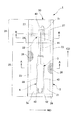
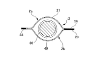
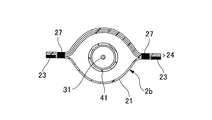
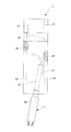
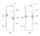
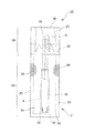
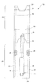
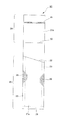
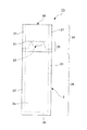
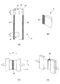
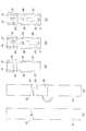
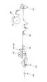
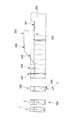
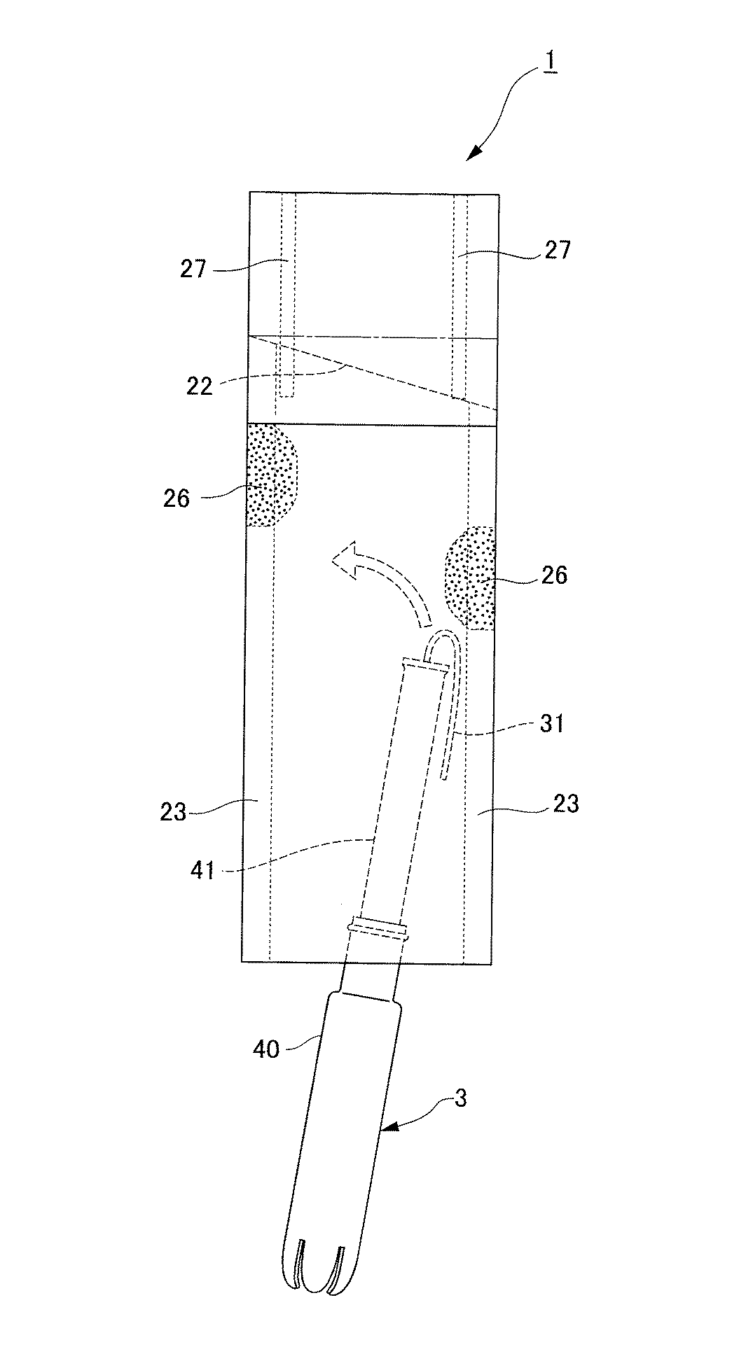
図1は、本発明の第1実施形態に係る個包装体の正面図である。図2は、図1における個包装体のA−A断面図である。図3は、図1における個包装体のB−B断面図である。図4は、図1における個包装体の開封状態を示す正面図である。図5は、本発明の実施形態に係るサイドシールとタンポン挿入の関係を示す個包装体の正面図である。図6は、シール部の位置関係を示す個包装体の正面図である。図7は、エンボスパターンを示す概略図である。図8は、エンボスパターンを説明するための蓋部の概略図である。図9は、エンボスパターンを示す概略図である。図10は、エンボスパターンを示す概略図である。 FIG. 1 is a front view of an individual package according to the first embodiment of the present invention. FIG. 2 is a cross-sectional view taken along line AA of the individual package in FIG. 3 is a cross-sectional view taken along the line BB of the individual package in FIG. FIG. 4 is a front view showing an opened state of the individual package in FIG. FIG. 5 is a front view of the individual package showing the relationship between the side seal and the tampon insertion according to the embodiment of the present invention. FIG. 6 is a front view of the individual package showing the positional relationship of the seal portions. FIG. 7 is a schematic view showing an emboss pattern. FIG. 8 is a schematic view of a lid for explaining the emboss pattern. FIG. 9 is a schematic view showing an emboss pattern. FIG. 10 is a schematic view showing an emboss pattern.
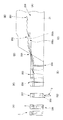
図11は、本発明の第2実施形態における個包装体の正面図である。図12は、図11における個包装体の開封状態を示す正面図である。図13は、本発明の第3実施形態における個包装体の正面図である。図14は、本発明の第4実施形態のおける個包装体の正面図である。図15は、図14における個包装体の開封状態を示す正面図である。図16は、本発明の第5実施形態における個包装体の正面図である。図17は、本発明の第6実施形態における個包装体の正面図である。図18は、ピール強度の試験状態を説明する図である。図19は、個包装体の製造方法を示す概略図である。図20は、個包装体が製造される状態を示す概略図である。図21は、個包装体の製造システムを示す概略図である。図22は、第4実施形態のおける個包装体が製造される状態を示す概略図である。 FIG. 11 is a front view of an individual package in the second embodiment of the present invention. FIG. 12 is a front view showing an unsealed state of the individual package in FIG. 11. FIG. 13 is a front view of an individual package in the third embodiment of the present invention. FIG. 14 is a front view of an individual package in the fourth embodiment of the present invention. FIG. 15 is a front view showing an unsealed state of the individual package in FIG. FIG. 16 is a front view of an individual package in the fifth embodiment of the present invention. FIG. 17 is a front view of an individual package in the sixth embodiment of the present invention. FIG. 18 is a diagram for explaining a peel strength test state. FIG. 19 is a schematic view showing a method for manufacturing an individual package. FIG. 20 is a schematic view showing a state in which an individual package is manufactured. FIG. 21 is a schematic view showing a system for manufacturing an individual package. FIG. 22 is a schematic view showing a state in which the individual package in the fourth embodiment is manufactured.
[第1実施形態]
(1)全体構成
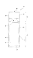
図1から図4に示すように、個包装体1は、外筒40及び内筒41を有するアプリケータ4を含むアプリケータ付タンポン3と、シート状部材である包装シート21により形成される略縦長状の略扁平袋体である包装袋2と、を備える。包装袋2は、収納部25を有し、アプリケータ付タンポン3は、この収納部25に収納されている。また、包装袋2は、ミシン目状に形成された開封部22と、この開封部22と連続し、開封部22を覆うように形成された蓋部24とを有する。蓋部24は、この蓋部24と一体に形成された把持部28を備える。収納部25の長手方向における両側部には、略半円状に形成され、内側に突出するように形成されたシール部26が形成されている。シール部26は、互いに向かい合う包装シート21を接合する。なお、本実施形態においては、シール部26を設けたが、本発明においてはこれに限らず、シール部26を設けない構成のものも用いることができる。
[First Embodiment]
(1) Overall Configuration As shown in FIGS. 1 to 4, the
(2)個包装体
(a)全長
この個包装体1の長手方向における長さは、例えば、アプリケータ4の全長に対して10mmから40mmを加えた長さが好ましい。具体的には、ロングタイプと持ち運びに便利なコンパクトタイプについて規定すると、ロングタイプにおいては、アプリケータ4の全長が145mmであるライト(ユニ・チャーム社製)は155mmから185mm、アプリケータ4の全長が116.5mmであるレギュラー(ユニ・チャーム社製)は127mmから157mm、アプリケータ4の全長が119.5mmであるスーパー(ユニ・チャーム社製)は130mmから160mm、アプリケータ4の全長が126mmである他の実施品は136mmから166mmを例示できる。また、コンパクトタイプにおいては、アプリケータ4の全長が85mmであるレギュラー(ユニ・チャーム社製)は95mmから125mm、アプリケータ4の全長が88mmであるスーパー(ユニ・チャーム社製)は、98mmから128mmを例示できる。
(2) Individual package (a) Full length The length in the longitudinal direction of the
(b)収納部長さ
個包装体1の収納部長さは、例えば、アプリケータの外筒の長さ以上であって、アプリケータ4の全長に対して10mm加えた長さ以下であればよい。具体的には、ロングタイプにおいては、外筒40の長さが101mm、アプリケータの全長が145mmであるライト(ユニ・チャーム社製)は101mmから155mm、外筒40の長さが68.5mm、アプリケータの全長が116.5mmであるレギュラー(ユニ・チャーム社製)は68.5mmから126.5mm、外筒40の長さが71.2mm、アプリケータの全長が119.5mm外であるスーパー(ユニ・チャーム社製)は71.2mmから129.5mm、外筒40の長さが71.8mm、アプリケータの全長が126mmである他の実施品は71.8mmから136mm、を例示できる。また、コンパクトタイプにおいては、外筒40の長さが63.5mm、アプリケータの全長が85mmであるレギュラー(ユニ・チャーム社製)は63.5mmから95mm、外筒40の長さが64mm、アプリケータの全長が88mmであるスーパー(ユニ・チャーム社製)は、64mmから98mm、を例示できる。
(B) Storage part length The storage part length of the
(c)幅
個包装体1の幅方向における長さは、例えば、アプリケータ4の外筒40の外径の180%から320%の範囲にあることが好ましい。さらに好ましくは、270%程度が好ましい。具体的には、ロングタイプにおいては、外筒40の外径が12.9mmであるライト(ユニ・チャーム社製)は23mmから41mm、好ましくは29mm。外筒40の外径が13.4mmであるレギュラー(ユニ・チャーム社製)は24mmから43mm、好ましくは、30mm。外筒40の外径が16.4mmであるスーパー(ユニ・チャーム社製)は30mmから52mm、好ましくは、36mm、外筒40の外径が17.6mmである他の実施品は23mmから56mm、好ましくは39mmを例示できる。また、コンパクトタイプにおいては、外筒40の外径が13.4mmであるレギュラー(ユニ・チャーム社製)は24mmから43mm、好ましくは、30mm。外筒40の外径が16mmであるスーパー(ユニ・チャーム社製)は、29mmから51mm、好ましくは、36mmを例示できる。
(C) Width The length of the
(d)サイドシール幅
個包装体1の長手方向における両側部のサイドシール幅は、例えば、3mmから6mmを例示できる。
(D) Side seal width The side seal width of the both side parts in the longitudinal direction of the
(e)蓋部
蓋部24に長手方向における長さは、例えば、個包装体1の全長に対して、この全長から収納部長さを引いたものを例示できる。具体的には、ロングタイプにおいては、個包装体1の全長が155mmから185mmであるライト(ユニ・チャーム社製)は20mmから104mm、個包装体1の全長が127mmから157mmであるレギュラー(ユニ・チャーム社製)は20mmから107mm、個包装体1の全長が130mmから160mmであるスーパー(ユニ・チャーム社製)は20mmから109mm、個包装体1の全長が136mmから166mmである他の実施品は80mmから115mmを例示できる。また、コンパクトタイプにおいては、個包装体1の全長が95mmから115mmであるレギュラー(ユニ・チャーム社製)は20mmから81.5mm、個包装体1の全長が98mmから118mmであるスーパー(ユニ・チャーム社製)は、20mmから84mmを例示できる。
(E) Lid part The length in the longitudinal direction of the
(f)把持部
蓋部24における把持部28は、例えば、5mmから20mmを例示できる。
(F) Gripping part The
(3)アプリケータ付タンポン
アプリケータ付タンポン3は、吸収体30と、この吸収体30の後端部から延びる紐31と、吸収体30及び紐31とを収納するアプリケータ4と、を備える。吸収体30は、例えば、コットンやレーヨンなどの親水性繊維を圧縮して、表面を不織布などの液透過性シートで包んだものである。吸収体30は、生理中の女性の膣腔内に挿入されると、経血等の体液を吸収し、膨張する。吸収体30を膣腔内に挿入しているときには、紐31を膣腔体から体外へ出しておき、この紐31を引くことにより使用後の吸収体30を膣内から取り出すことができる。
(3) Tampon with applicator The tampon with
アプリケータ4は、合成樹脂材料で形成されているものであり、吸収体30を収納している外筒40と、吸収体30の後端部に対向して外筒40に対して摺動自在に挿入された内筒41と、を有している。外筒40の先端部には、複数の花弁42が互いに分割されて一体に形成されている。また、吸収体30の後端部から延びる紐31は、内筒41内に挿通されて内筒41の後端部43から後方へ突出している。このアプリケータ付タンポン3を使用するときには、アプリケータ4の外筒40を膣腔内に挿入し、内筒41を外筒40の内部に押し込む。このとき、内筒41によって外筒40内の吸収体30が押し出され、外筒40の先端部分の花弁42が開くように変形されて、吸収体30が膣内に挿入される。
The
(4)包装袋
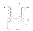
包装袋2は、包装シート21を折り返し部50において折り曲げることにより、一方側である一方の面2a及び他方側である他方の面2bを有する略扁平状に形成されている。互いに向かい合う一方及び他方の面2a、2bは、長手方向における両側部であるサイドシール部23において、接合されている。また、折り返し部50と対向する端部であるボトムシール部29においても、一方及び他方の面2a、2bは、接合されている。包装袋2の一方の面2aには、他方の面2bから折り返して形成される折り返し部50の近傍に蓋部24が設けられている。蓋部24には、この蓋部24の一部を内面、すなわち一方の面2a側に折り返して形成される把持部28が設けられている。また、一方の面2aには、開封部22が設けられおり、開封部22と、蓋部24及び把持部28は、包装シート21において連続して一体に形成されており、開封部22は、蓋部24に覆われた状態で形成されている。
(4) Packaging bag The
開封部22は、ミシン目状に形成されている。開封部22は、このミシン目により蓋部24と切り離し可能となっている。すなわち、蓋部24は、開封部22のミシン目を破ることにより長手方向に開閉可能となる。ミシン目は、例えば、レーザー装置(Keyence社製 CO2LASER MARKER ML−G930)を用いることにより形成することができる。なお、開封部22は、第1実施形態においては、包装袋2の幅方向に横切る直線的なミシン目によって形成されているが、本発明においてはこれに限らず、半円状、波状、山型状等に形成してもよい。また、長手方向に対して直行する方向に設けられてもよい。好ましくは、所定の角度を有する斜め方向に形成されることが好ましい。斜め方向に形成された場合には、開封部22の間口が広くなり、より使用済みのアプリケータ4を入れやすくなる。さらに、開封部22は、ミシン目により形成されていなくてもよく、規定した線の通りに切り離し可能な形状であればよい。
The opening
蓋部24は、把持部28を有する。把持部28は、蓋部24を一方の面2a側に折り返すことにより形成されている。具体的には、蓋部24の山折り部52を包装シート21の内面側に山折りし、谷折り部51を他方の面2b側に折り返すことにより形成される。なお、第1実施形態においては、把持部28は、略矩形状に形成されているが、本発明においてはこれに限らず、略半円形状に形成されていてもよい。
The
長手方向における蓋部24の両側部には、蓋部24と他方の面2bとを接着する蓋部接着部27が設けられている。各蓋部接着部27は、蓋部24の長手方向における両側端部に設けられてもよい。また、蓋部接着部27は、把持部28の少なくとも一部を含んで接着されてもよい。包装袋2の蓋部24と長手方向において対向する下端部には、一方及び他方の面2a、2bを接合するボトムシール部29が形成されている。収納部25の長手方向における両縁部には、一方及び他方の面2a、2bの包装シート21が接合されたサイドシール部23が形成されている。
On both side portions of the
このサイドシール部23には、一方及び他方の面2a、2bの包装シート21の一部を接合し、包装袋2の長手方向における中心軸に向かって突出するように略半円状に形成されたシール部26が設けられている。シール部26は、略半円形に形成されており、それぞれが包装袋2の内側に突出するように形成されている。なお、本実施形態においては、シール部26は、略半円状に形成されるが、本発明においてはこれに限らず、角切り処理を施した形状であればよい。具体的には、例えば、角切り処理を施した台形等の形状であってもよい。これにより、図5に示すように、製造工程時のアプリケータ付タンポン3挿入において、アプリケータ付タンポン3がシール部26に突き当たっても、角きり処理を施しているため、引っかかることなく速やかに挿入することが可能になる。
A part of the
また、使用済みのアプリケータ4を開封口から入れる場合においても、アプリケータ4の外筒40がシール部26に突き当たった場合においても、引っかかることなく包装袋2に挿入することが可能になる。さらに、アプリケータ付タンポン3を略中心部において安定させることも可能になる。この場合において、長手方向に互いに離間して設けた場合には、収納部25の幅を広く取ることが可能になる(図6参照)。
In addition, even when the used
個包装体1は、包装シート21により形成されており、内面にはエンボス加工が施されている。包装シート21としては、例えば、高密度ポリエチレン(HDPE)、低密度ポリエチレン(LDPE)、直鎖状低密度ポリエチレン(LLDPE)、およびこれらの配合からなるフィルムを用いることができる。好ましくは、目付が20g/m2から35g/m2の上記材料を用いることができる。また、これらは、単層であってもよく、複数層からなっていてもよい。なお、包装シートは、上記に限られることなく、例えば、ポリプロピレン(PP)、EVA樹脂(EVA)、PET樹脂(PET)、塩化ビニル樹脂(PVC)などの熱可塑性樹脂、生分解性フィルム、不織布、ラミネートフィルム、及び和紙等の単体、又はこれらを組み合わせたものを用いてもよい。
The
包装シート21は、この包装シート21を袋状の個包装状態にしたときに向き合うフィルムの内面にコロナ処理やシリコン処理等のリケイ処理を一部または全体に施したものでもよい。これらの処理を行うことにより、包装シートの摩擦係数が低くなり、包装シート同士が貼り付きにくくなるためである。
The
包装シート21の表面粗さは、摩擦係数の変動を示すMMD値が0.03から0.06であることが好ましい(KES表面粗さ試験)。MMD値が低すぎると、各包装シート21の接地面積が多く、摩擦も起こりにくく、滑りにくくなるためである。また、MMD値が高すぎると、向き合った内面の凹凸が噛み合ってしまい、滑りにくくなるためである。
As for the surface roughness of the
包装シート21の曲げ剛性は、1cm2あたりの曲げ剛性値を示すB値が0.005×10⁻⁴Nm/mから0.040×10−4Nm/m(KES曲げ剛性試験)であることが好ましい。
Flexural rigidity of the
包装シート21は、この包装シート21を袋状の個包装状態にしたときに向き合うフィルムの内面にエンボス加工が施されている。エンボス加工としては、例えば、エンボスロールを用い、エンボス温度が常温から4℃であって、丸型のパターンを千鳥配列し、フィルム成形後のパターンの高さが90μmのものを用いることができる。また、エンボス加工は、エンボス加工後の包装シートの厚みが0.07mmから0.13mmであることが好ましい。
The
ここで、包装袋2におけるサイドシール部23、蓋部接着部27、およびボトムシール部29におけるエンボス状のパターン加工されたヒートシール加工について説明する。ヒートシール加工は、例えば、シール温度が80℃から110℃、圧力が15kgf/cm2から30kgf/cm2の範囲を例示できる。
Here, the embossed pattern-processed heat sealing process in the
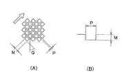
また、ヒートシールのエンボスパターンとしては、図7に示すように、サイドシール部23においては、溝深さMが1.0mm、天口Nが0.8×0.8mm、ピッチPが1.5mm、傾斜角Qが45°のものが用いられ、形状は、千鳥格子を例示できる。蓋部接着部27においては、溝深さMが1.0mm、天口Nが0.6×0.6mm、ピッチPが1.5mm、傾斜角Qが45°のものが用いられ、形状は、千鳥格子が例示できる。ボトムシール部29においては、溝深さMが1.0mm、天口Nが0.8×0.8mm、ピッチPが1.2mm、傾斜角Qが45°のものが用いられ、形状は、千鳥格子が例示できる。なお、蓋部接着部27は、エンボスパターンとして、溝深さMが1.0mm、天口Nが0.3×1.2mm、ピッチPが1.0mm、傾斜角Qが45°であって、形状が長方形のものを用いることもできる。このように、エンボスの形状を長方形にすることで蓋部24をはがし易くすることができる。
Moreover, as an embossing pattern for heat sealing, as shown in FIG. 7, in the
包装シート21は、ヒートシールの温度が高い場合、包装シート21同士が溶融により剥がれにくくなることがある。したがって、蓋部24においては、図8に示すように、蓋部接着部27の略中央部と内側の端部とをパターンの異なるピッチR、Sにすることで、例えば、長方形状のエンボスと非エンボスとの境目から破れることが容易となり、蓋部24を剥がれ易くすることができる。蓋部24を剥がれ易いように形成することにより、長手方向に開封し易くなる。
When the temperature of heat sealing is high, the
具体的には、例えば、図9に示すようなエンボスパターンを例示できる。図9は、略中央部に溝深さM(図7(B)参照)が1mm、天口Nが0.6×0.6mm、ピッチPが1.4mm、傾斜角Q(図7(A)参照)が45°であって、形状は、千鳥格子状に形成したパターンAを有する。そして、内側の端部には、ピッチSが1mmで、一辺が0.6mmの略三角形であるパターンBを有する。このように、内側の端部のピッチSが1mmであるのに対し、中央部のピッチRが2mmとすることにより、内側端部のピッチが狭くなり、蓋部24が長手方向に開封し易くなる。
Specifically, for example, an emboss pattern as shown in FIG. 9 can be exemplified. In FIG. 9, the groove depth M (see FIG. 7B) is 1 mm, the top N is 0.6 × 0.6 mm, the pitch P is 1.4 mm, and the inclination angle Q (see FIG. 7A). ) Reference) is 45 °, and the shape has a pattern A formed in a staggered pattern. The inner end portion has a pattern B which is a substantially triangular shape having a pitch S of 1 mm and a side of 0.6 mm. Thus, while the pitch S of the inner end portion is 1 mm, the pitch R of the inner end portion is narrowed by setting the pitch R of the central portion to 2 mm, and the
また、図10に示すように、内側の端部は、中央部におけるパターンAに加え、端部にピッチSが1mmで、1.0×2.0mmの長手方向に延びる長方形であるパターンDを用いる。これにより、内側の端部のピッチSが1mmであるのに対し、中央部のピッチRが2mmとすることにより、内側端部のピッチが狭くなり、蓋部24を長手方向に開封し易くなる。
Further, as shown in FIG. 10, in addition to the pattern A in the central portion, the inner end portion has a pattern D that is a rectangle having a pitch S of 1 mm and extending in the longitudinal direction of 1.0 × 2.0 mm at the end portion. Use. Thereby, while the pitch S of the inner end portion is 1 mm, the pitch R of the inner end portion is narrowed by setting the pitch R of the central portion to 2 mm, and the
[第2実施形態]
第2実施形態に示す個包装体1Aは、第1実施形態における個包装体1と類似する。以下、第2実施形態における個包装体1Aを、第1実施形態における個包装体1との相違点を中心に説明する。
[Second Embodiment]
An
図11及び図12に示すように、第2実施形態に係る個包装体1Aは、開封部22が山型に形成されている。すなわち、ミシン目が山型に形成されている。具体的には、蓋部24側及び収納部25側に形成される開封部22の略中央部に山型が形成される。一方、収納部25側に形成される開封部22の一部は、谷折り部51において折り返されている。このそれぞれの山型形状がミシン目により形成され、接続されている。このように、開封部22のミシン目が山型に形成されることにより、間口が開きやすくなる。これにより、使用済みのアプリケータを入れ戻しやすくなる。
As shown in FIG.11 and FIG.12, the
また、第2実施形態においては、シール部26のそれぞれは、対向して設けられている。このように、シール部26が対向して設けられることにより、アプリケータ付タンポン3を略中央部において安定した状態で保持することができる。また、例えば、開口部に対して略並行にそれぞれのシール部26を設けることにより、安定した形状の間口を形成し易くなる。
Moreover, in 2nd Embodiment, each of the
[第3実施形態]
第3実施形態に示す個包装体1Bは、第1実施形態における個包装体1と類似する。以下、第3実施形態における個包装体1Bを、第1実施形態における個包装体1との相違点を中心に説明する。
[Third Embodiment]
The
図13に示すように、第3実施形態に係る個包装体1Bは、蓋部24に設けられる把持部28が略円形状に形成される。このように、蓋部24に設けられる把持部28は、矩形のみでなく、角きり処理の施された略半円形等を用いることができる。
As shown in FIG. 13, in the
[第4実施形態]
第4実施形態に示す個包装体1Cは、第1実施形態における個包装体1と類似する。以下、第4実施形態における個包装体1Cを、第1実施形態における個包装体1との相違点を中心に説明する。
[Fourth Embodiment]
An individual package 1C shown in the fourth embodiment is similar to the
図14及び図15に示すように、第4実施形態に係る個包装体1Cは、一方及び他方の面を形成する包装シート21a、21bが別体に設けられて形成されている。すなわち、一方の面を構成する包装シート21aと、他方の面を構成する包装シート21bとを用い、互いに対向させ、長手方向における両側部を接合させることにより、略扁平袋体を形成する。蓋部24は、折り返し部50において折り返されることにより形成されている。蓋部24の長手方向における端部には、把持部28が設けられている。蓋部24における長手方向の両側部は、包装シート21aの一部及び包装シート21bと長手方向に形成された蓋部接着部27により接合されている。また、蓋部24の間口の近傍である端部は、幅方向に形成された蓋部接着部61において、例えば、ホットメルトにより接着されている。
As shown in FIGS. 14 and 15, the
[第5実施形態]
第5実施形態に示す個包装体1Dは、第1実施形態における個包装体1と類似する。以下、第5実施形態における個包装体1Dを、第1実施形態における個包装体1との相違点を中心に説明する。
[Fifth Embodiment]
An
図16に示すように、第5実施形態に係る個包装体1Dは、開封部22が山型に形成されている。すなわち、ミシン目が山型に形成されている。具体的には、蓋部24側及び収納部25側のそれぞれに形成される開封部22の略中央部に山型が形成される。一方、収納部25側に形成される開封部22の一部は、山型の一部が谷折り部51において折り返されている。このそれぞれがミシン目により接合されている。なお、第5実施形態における個包装体1Dは、例えば、全長が145mm、幅が45mm、蓋部24の長手方向における長さが60mm、収納部長さが98mmを例示できる。また、把持部28を13mmとし、サイドシール幅及びボトムシール幅は、共に5mmを例示できる。
As shown in FIG. 16, the
第5実施形態に係る個包装体1Dは、蓋部24とサイドシール部23とを一度にエンボス加工することができる。具体的には、サイドシール部23及び蓋部接着部27のそれぞれのシール幅を5mmとして、それぞれ長手方向の両側部にエンボス加工することができる。この場合、蓋部接着部27と、サイドシール部23とは、それぞれ異なるパターンのエンボス加工を用いてもよい。この場合、蓋部接着部27がサイドシール部23よりピール強度が低くなるようなパターンを選ぶことが好ましい。このように、開封部22のミシン目が山型に形成されることにより、間口が開きやすくなり、一度のエンボス加工が可能になるため、個包装体1Dの成形が容易になる。
The
[第6実施形態]
第6実施形態に示す個包装体1Eは、第5実施形態における個包装体1Dと類似する。以下、第6実施形態における個包装体1Eを、第5実施形態における個包装体1Dとの相違点を中心に説明する。
[Sixth Embodiment]
The
図17に示すように、第6実施形態に示す個包装体1Eは、サイドシール幅と蓋部接着幅を異なる幅としてもよい。例えば、蓋部接着幅をサイドシール幅よりも狭くすることにより、エンボス面積を小さくし、蓋部24を開封し易くすることもできる。なお、この場合、蓋部接着部27と、サイドシール部23とは、それぞれ異なるパターンのエンボス加工を用いてもよく、同じエンボスパターンを用いてもよい。
As shown in FIG. 17, the
以下、実施例を挙げて、包装シートの最適な資材について検討する。 In the following, examples will be given to examine the optimal materials for packaging sheets.
<実施例1>
目付が23g/m2、エンボス加工ありのポリエチレンフィルム(PE)を使用して、表面粗さ及び曲げ剛性について試験した。
(表面粗さ試験)
KES試験:使用器具 カトーテック株式会社製、KES FB−4S
サンプル:縦100mm、横100mm
算出方法:MMD値(表面粗さ)=(MD方向MMD値+CD方向MMD値)/2
(曲げ剛性試験)
KES試験:使用器具 カトーテック株式会社製、KES FB−2
サンプル:縦100mm、横100mm
算出方法:B値(曲げ剛性)=MD方向B値 (10−4Nm/m)
MD方向:幅方向、CD方向:長手方向
<Example 1>
Using a polyethylene film (PE) having a basis weight of 23 g / m 2 and embossing, surface roughness and bending rigidity were tested.
(Surface roughness test)
KES test: Instruments used Kato Tech Co., Ltd., KES FB-4S
Sample: 100 mm long, 100 mm wide
Calculation method: MMD value (surface roughness) = (MD direction MMD value + CD direction MMD value) / 2
(Bending stiffness test)
KES test: Instruments used Kato Tech Co., Ltd., KES FB-2
Sample: 100 mm long, 100 mm wide
Calculation method: B value (bending rigidity) = MD direction B value (10 −4 Nm / m)
MD direction: width direction, CD direction: longitudinal direction
<実施例2>
目付が30g/m2、エンボス加工ありのポリエチレンフィルム(PE)を用いて、実施例1と同条件で試験した。
<Example 2>
Using a polyethylene film (PE) with a basis weight of 30 g / m 2 and embossing, the test was performed under the same conditions as in Example 1.
<実施例3>
目付が35g/m2、エンボス加工ありのポリエチレンフィルム(PE)を用いて、実施例1と同条件で試験した。
<Example 3>
Using a polyethylene film (PE) with a basis weight of 35 g / m 2 and embossing, the same conditions as in Example 1 were tested.
<比較例1>
目付が23g/m2、エンボス加工なしのポリエチレンフィルム(PE)を用いて、実施例1と同条件で試験した。
<Comparative Example 1>
Using a polyethylene film (PE) with a basis weight of 23 g / m 2 and no embossing, the test was performed under the same conditions as in Example 1.
<比較例2>
目付が30g/m2、エンボス加工なしのポリプロピレンフィルム(PP)を用いて、実施例1と同条件で試験した。
<Comparative example 2>
A polypropylene film (PP) having a basis weight of 30 g / m 2 and having no embossing was used and tested under the same conditions as in Example 1.
[評価]
(a)開封しやすさ
◎:非常に開封しやすい
○:開封しやすい
×:開封しにくい
(b)音の大きさ
○:音が小さい
×:音が大きい
(c)柔らかさ
◎:非常に柔らかい
○:柔らかい
×:硬い
[Evaluation]
(A) Ease of opening ◎: very easy to open ○: easy to open ×: difficult to open (b) loudness ○: low sound ×: loud sound (c) soft ◎: very easy Soft ○: Soft ×: Hard
以上の結果から明らかなように、比較例1のようにエンボス加工の施されていない包装シートは、官能評価として開封しにくいと評価されるため、個包装体1に使用するシートに適さないことがわかる。また、比較例2のように、エンボス加工が施されず、かつ、ポリプロピレンフィルム(PP)を使用したものは、官能試験において、開封しにくく、大きな音が発生し、しかも包装シートが硬いと評価されるため、比較例1と同様に個包装体1に使用するシートに適さないことがわかる。
As is clear from the above results, a packaging sheet that has not been embossed as in Comparative Example 1 is evaluated as being difficult to open as a sensory evaluation, and thus is not suitable for a sheet used for the
次に、サイドシール部23及び蓋部接着部27のピール強度について検討する。図18(B)に示すように包装袋2におけるA部及びB部を切り取り、オートグラフのチャックに両端を挟み(図18(C)及び(D)参照)、試験した。
Next, the peel strength of the
<実施例4>
エンボス温度が99℃から106℃、エンボス圧力が20kgf/cm2の範囲において、目付が30g/m2、エンボス加工を有するポリエチレンフィルム(PE)を使用して、ピール強度について試験した。
<Example 4>
Peel strength was tested using an embossed polyethylene film (PE) having an embossing temperature of 99 ° C. to 106 ° C. and an embossing pressure of 20 kgf / cm 2 and a basis weight of 30 g / m 2 .
[使用器具]
島津システムソリューションズ株式会社製、オートグラフAG−1
[Usage equipment]
Autograph AG-1 manufactured by Shimadzu System Solutions Co., Ltd.
[評価サンプル]
図18(A)におけるA部(サイドシール部23)、B部(サイドシール部23)について、試験片(縦a:25mm)を用いて試験した。
[Evaluation sample]
A part (side seal part 23) and B part (side seal part 23) in FIG. 18 (A) were tested using a test piece (vertical a: 25 mm).
[エンボスパターン]
サイドシール部については、溝深さ:1.0mm、天口:0.8×0.8mm、ピッチ:1.5mm、配置:45°のものを用いた。
蓋部接着部については、溝深さ:1.0mm、天口:0.6×0.6mm、ピッチ:1.5mm、配置:45°のものを用いた。
[Emboss pattern]
About the side seal part, the groove depth: 1.0 mm, the top: 0.8 × 0.8 mm, the pitch: 1.5 mm, and the arrangement: 45 ° were used.
For the lid bonding part, the groove depth: 1.0 mm, top: 0.6 × 0.6 mm, pitch: 1.5 mm, and arrangement: 45 ° were used.
[評価方法]
チャック間を20mmとし、ピール速度を100mm/minとして試験した。
[Evaluation methods]
The test was conducted with the chuck spacing of 20 mm and the peel speed of 100 mm / min.
[評価]
以上により、サイドシール部23では、比較的ピール強度(最大試験力)が高いことがわかる。蓋部接着部27においては、比較的ピール強度(最大試験力)が低いため、蓋部24が剥がれやすい事がわかる。
[Evaluation]
From the above, it can be seen that the
[製造方法]
次に、本発明に係る個包装体1の製造方法について説明する。本発明に係る個包装体1の製造方法は、外筒40及び内筒41を有するアプリケータ4と、前記アプリケータ4から押し出し可能に収納される吸収体30と、を備えるアプリケータ付タンポン3が、所定の包装シート21により形成される略縦長状の包装袋2に個別に封入される個包装体1の製造方法であって、図19に示すように、該シート供給工程により供給された包装シート21に対して、所定位置にミシン目を形成するミシン目形成工程と、包装シート21の一部を折り込むことにより、所定位置に把持部28を形成する把持部形成工程と、包装シート21を所定位置で折り返すことにより、蓋部24を形成する蓋部形成工程と、蓋部形成工程により折り返された包装シート21を接合する接合工程と、所定形状に形成されたシール部26を形成するシール部形成工程と、開口にアプリケータ付タンポン3を挿入するタンポン挿入工程と、開口を接合する開口部接合工程と、を含む。
[Production method]
Next, the manufacturing method of the
本発明における製造方法が製造する対象は、外筒40及び内筒41を有するアプリケータ4と、前記アプリケータ4から押し出し可能に収納される吸収体30と、を備えるアプリケータ付タンポン3が、所定のシート状部材である包装シート21により形成される略縦長状の略扁平袋体である包装袋2に個別に封入される個包装体1である。
An object to be manufactured by the manufacturing method according to the present invention is an
図19(A)に示すように、ミシン目形成工程は、例えば、所定のレーザー装置等のミシン目カット手段により、包装シート21が切り離し可能になるように略縦長状の包装シート21の所定の位置にミシン目を形成する。なお、ミシン目カット手段は、レーザー装置等によるものほかに、ミシン目状の刃のついたローリーカッター等によるものも使用することができる。
As shown in FIG. 19A, in the perforation forming step, for example, a predetermined perforation of the substantially vertically
図19(B)に示すように、把持部形成工程は、包装シート21をセーラー状に折り重ねることにより形成される。具体的には、包装シート21の谷折り部51を裏面側に折り込む。次いで、包装シート21の山折り部52を表面側に折り込む。このように、谷折り部51と山折り部52のそれぞれを所定方向に折り込むことにより、把持部28が形成される。蓋部形成工程は、把持部形成工程により形成された把持部28をさらに、表面側に折り込む。これにより、包装シート21は、各面が対向した略扁平状に形成され、表面側に蓋部24が形成される事となる。
As shown in FIG. 19B, the gripping portion forming step is formed by folding the
図19(C)に示すように、接合工程は、折り込まれた包装シート21の長手方向の両端部を接合する。具体的には、長手方向後端部から、ミシン目形成位置までを接合する。これにより、包装袋2の袋体が形成される。ついで、蓋部24の長手方向の両端部を接合する。このとき、蓋部24の接合は、取り外し可能の状態で接合される。
As shown in FIG. 19C, the joining step joins both ends of the folded
シール部形成工程は、略扁平袋状に形成された袋体の互いに向かい合う各面の長手方向の両側部の所定位置を所定形状に接合する。これにより、シール部26が形成される。
In the sealing portion forming step, predetermined positions on both side portions in the longitudinal direction of the surfaces facing each other of the bag body formed in a substantially flat bag shape are joined in a predetermined shape. Thereby, the
図19(D)に示すように、タンポン挿入工程は、シール部接合工程により形成された袋体にアプリケータ付タンポン3を挿入する。
As shown in FIG. 19D, in the tampon insertion step, the
図19(E)に示すように、開口接着工程は、タンポン挿入工程によりアプリケータ付タンポン3が挿入された袋体の下端の開口を接合し、アプリケータ付タンポン3を封入する。これにより、個包装体1が形成される。
As shown in FIG. 19 (E), in the opening bonding step, the opening at the lower end of the bag body into which the
[製造システム]
工業的に生産する場合においては、例えば、以下のような製造システムを使用することができる。
[Manufacturing system]
In the case of industrial production, for example, the following production system can be used.
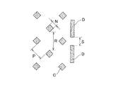
本発明に係る個包装体1を製造する製造システムは、外筒40及び内筒41を有するアプリケータ4と、このアプリケータ4から押し出し可能に収納される吸収体30と、を備えるアプリケータ付タンポン3が、所定のシート状包装材200により形成される略縦長状の包装袋2に個別に封入される個包装体1の製造システムであって、図20及び図21に示すように、シート状包装材200を一定方向に供給するシート供給手段100と、該シート供給手段100により供給されたシート状包装材200に対して、所定位置にミシン目201を形成するミシン目形成手段101と、シート状包装材200の一部202を折り込むことにより、所定位置に把持部28を形成する把持部形成手段102と、シート状包装材200を所定位置203で折り返す折り返し手段103と、該折り返し手段103により折り返されたシート状包装材200の幅方向の少なくとも一部を所定の間隔で接着する接着手段104と、所定形状に形成されたシール部26を形成するシール部形成手段105と、該接着手段104により接着されたシート状包装材200を所定間隔で切り離す切り離し手段106と、開口にアプリケータ付タンポン3を挿入するタンポン挿入手段107と、開口208を接合する開口接合手段108と、を含む。
The manufacturing system for manufacturing the
シート供給手段100は、例えば、ドラム等にロールされた所定のシート状包装材200を一定方向に向けて所定の速度で供給する。例えば、シート状包装材200は、図20の(A)部に示すような状態で供給される。なお、所定のシート状包装材200とは、裏面又は表面にエンボス加工がなされたシート状包装材を含み、この場合、図示しないエンボス加工工程を設けてもよい。
The
ミシン目形成手段101は、例えば、図20(B)部に示すように、所定のカッター等により、開封部22に該当する所定の位置に開封可能にミシン目201を形成する。カッターとしては、例えば、レーザー装置(Keyence社製 CO2LASER MARKER ML−G930)を用いることができる。また、ミシン目形成手段は、レーザー装置等によるものほかに、ミシン目状の刃のついたローリーカッター等によるものも使用することができる。
For example, as shown in FIG. 20B, the perforation forming means 101 forms a
把持部形成手段102は、例えば、図20(C)部に示すように、シート状包装材200をセーラー状に折り重ねることにより、把持部28を形成する。具体的には、シート状包装材200の谷折り部202aにおいて、これを裏面側に折り込む。次いで、シート状包装材200の山折り部202bにおいて、これを表面側に折り込む。このように、谷折り部202a及び山折り部202bのそれぞれを所定方向に折り込むことにより、把持部28が形成される。
For example, as shown in FIG. 20C, the grip portion forming means 102 forms the
折り返し手段103は、例えば、図20(D)部に示すように、把持部形成手段102により形成された把持部28を含むシート状包装材200の一部をさらに表面側に折り込む。これにより、シート状包装材200は、略扁平状に形成される。折り返し手段103は、例えば、図示しない2折りセーラー手段を用いて形成することができる。
For example, as shown in FIG. 20D, the folding means 103 further folds a part of the sheet-shaped
接着手段104は、例えば、図20(E)部に示すように、シート状包装材200の製袋時に内側となる面の内、すなわち、サイドシール部23に該当する部位204をヒートシール等により接合する。また、蓋部接着部27に該当する部位205は、ホットメルト等による接着剤を吹きつけ接着する。なお、接着手段は、シート状包装材200が接着できる手段であればよく、例えば、融着、圧着等であってもよい。また、エンボス加工を伴うものであってもよい。これにより、後端部が開口した袋状に形成される。
For example, as shown in FIG. 20 (E), the bonding means 104 is configured to heat-seal a
図示しないシール部形成手段105は、サイドシール部23に該当する部位204において、所定の形状にシート状包装材200の一部を接合する。接合は、接着手段104と同様であってもよい。
A seal portion forming means 105 (not shown) joins a part of the sheet-
切り離し手段106は、例えば、図20(F)部に示すように、シート状包装材200を個々の包装シート21を形成するように所定の位置206において、所定間隔で切り離す。
For example, as shown in FIG. 20 (F), the separating means 106 separates the sheet-shaped
タンポン挿入手段107は、例えば、図20(G)部に示すように、袋状に形成された包装シート21の下端の開口208を開き、アプリケータ付タンポン3をこの開口208より挿入させる。このときアプリケータ付タンポン3は、アプリケータ4の内筒41方向から挿入させる。
For example, as shown in FIG. 20 (G), the tampon insertion means 107 opens the
開口接合手段108は、例えば、図20(H)部に示すように、アプリケータ付タンポン3を挿入した包装袋2の開口208を接合し、アプリケータ付タンポン3を封入する。これにより、個包装体1が完成する。なお、製造システムには、各種ガイドローラが設けられている。
For example, as shown in FIG. 20 (H), the opening joining means 108 joins the
図22に第4実施形態である表面側シート状包装材300と裏面側シート状包装材302のそれぞれを用いた場合に係る個包装体1Cの製造システムを示す。図22に示すように、まず、カット手段により、表面側シート状包装材300の所定の位置301を斜めにミシン目状にカットする。次いで、表面側シート状包装材300と裏面側シート状包装材302とを合流させ、収納部25に該当する部位304において表面側シート状包装材300と裏面側シート状包装材302とを接合手段により接合する。
FIG. 22 shows a manufacturing system of the individual package 1C according to the case where each of the front-side sheet-
さらに、裏面側シート状包装材302の所定の位置にホットメルト等による接着剤を吹きつける。次いで、折り返し手段により、折り返し部305を折り返す。折り返し手段には、例えば、折り返しセーラー手段を用いることができる。
Further, an adhesive such as hot melt is sprayed on a predetermined position of the back side sheet-shaped
次に、接合手段により、蓋部接着部27に該当する部位306を接合する。さらに、切り離し手段により、表面側及び裏面側シート状包装材300、302を個々の包装シート21を形成するように所定の位置307において、所定間隔で切り離す。
Next, the site |
タンポン挿入手段により袋状に形成された包装シート21の下端の開口309を開き、アプリケータ付タンポン3をこの開口309より挿入させる。このときアプリケータ付タンポン3は、アプリケータ4の内筒41方向から挿入させる。
The
開口接合手段により、アプリケータ付タンポン3を挿入した包装袋2の開口309を接合し、アプリケータ付タンポン3を封入する。これにより、個包装体1が完成する。
By the opening joining means, the
個包装体1によれば、包装袋2の略扁平状における一方側にアプリケータ付タンポン3を取り出し可能に形成される開封部22と、包装袋2の長手方向に開閉可能な蓋部24と、を設けることにより、開封部22における所定の開口形状の安定した間口を得ることが可能になる。また、開封部22を蓋部24が覆う構成とするため、開封部22において蓋部24が隆起し、開封部22の位置が分り易くなる。また、例えば、開封部22の形状を山形に形成した場合においては、開封部22における間口が広がりやすくなり、使用済みのアプリケータ4が入れやすくなる。また、蓋部24を設けたことにより、使用済みのアプリケータ4を収納した後に、蓋をすることが可能となるため、開封後の包装袋2を清潔に保つことが可能になる。さらに、例えば、蓋部24に再接着が可能な接着手段を用いて接着させておくことにより、開封後においても再度蓋部24を接着することが可能になり、開封後の包装袋2を清潔に保つことができる。
According to the
個包装体1によれば、開封部22は、蓋部24と連続して形成され、蓋部24と切り離し可能なミシン目状に形成される。これにより、開封部22の開封が蓋部24の長手方向に向かう開封操作によるものとなる。また、ミシン目状の開封部22は蓋部24で覆われており、ミシン目を破るまで開封部22の間口は開かないため、包装袋2に封入されているアプリケータ付タンポン3が直接外気に触れる事がなく、清潔に保つことができる。
According to the
個包装体1によれば、蓋部24は、この蓋部24と一体に形成された把持部28を有する。これにより、開封時において、把持部28を用いて開封することが可能になるため、包装袋2の開封が容易になる。ここで、一体に形成されるとは、例えば、蓋部24の一部を把持部28として使用することを含む。また、把持部28は、蓋部24を形成する包装袋2を折り返して形成してもよい。このように折り返して把持部28を形成することにより、把持部28が隆起し、立体的に形成されるため、開封部22を容易に知ることが可能となる。
According to the
個包装体1によれば、包装袋2は、アプリケータ付タンポン3が収容される収納部25の内面側を形成する面に凹凸加工、例えば、エンボス加工が施されている。これにより、包装袋2を形成する包装シート21同士の接触面積が減り、包装シート21同士が貼り付きにくくなると同時に、はがれ易くなる。また、包装シート21の内面に凹凸が存在することで、包装シート21の剛軟度に差異、すなわち、比較的軟らかな部分と比較的剛質な部分が生じる。これにより、軟らかな部分が剛質な部分から力を受けることにより包装シート21が曲がり易くなる。したがって、包装袋2の開封が容易になると共に、開封時において所定の空間部を形成し易くなる。
According to the
なお、エンボス加工は、包装袋2を形成する包装シート21の表面に形成されていてもよい。すなわち、少なくとも包装袋2の内面に凹凸加工が施されていればよく、内面及び表面に施されていてもよい。包装袋2の表面上に凹凸加工が施されることで、開封時における滑り止めとすることができる。
Note that the embossing may be formed on the surface of the
個包装体1によれば、包装袋2の側部にシール部26を形成することにより、接合された包装シート21同士が一体化し、シール部26の剛性が高くなる。このため、シール部26における包装シート21は動きにくくなり、開封部22の間口の幅に比べてシール部26における包装シート21の可動範囲が狭くなる。このような包装シート21の可動範囲の差異により、包装シート21をスライドさせたときに生じる幅広なたくりが間口側に生じ、間口に空間が生じ易くなる。これにより、タンポン使用後のアプリケータ4は、間口に空間が生じた包装袋2に入れ易くなる。また、シール部26は持ち手として使用することも可能であるため、取り扱いも容易になる。
According to the
個包装体1によれば、シール部26は、包装袋2の長手方向に対して略半円形状に突出するように形成される。すなわち、シール部26の形状は、角部を有さない角切り処理が施してある。これにより、例えば、この包装袋2にアプリケータ4若しくはアプリケータ付タンポン3を挿入する場合において、アプリケータ4の内筒41または外筒40が、シール部26に突き当たっても角切り処理を施してあるため、引っかかることなく速やかに包装袋2の内部に挿入することが可能になる。また、包装袋2の両方の側部にこのシール部26が形成されている場合においては、シール部26がアプリケータ4若しくはアプリケータ付タンポン3を略中央部に誘導し、安定させることが可能になる。
According to the
個包装体1によれば、開封部22は、包装袋2の長手方向と所定の角度を有するように形成されている。すなわち、長手方向に対して、斜め方向に形成されている。これにより、開封部22における間口を広くとることができる。また、各シール部26は、それぞれのシール部26同士が形成する幅方向における傾斜角がこの開封部22と同角度をなすように互いに離間して設けられている。これにより、開封部22を開封する際に、例えば、開封部22に力が伝わりやすくなる。これにより、包装袋2を容易に開封することが可能になる。
According to the
個包装体1によれば、包装袋2の幅方向における長さをアプリケータ4の外筒40の最大外径よりも幅広に形成する。具体的には、最大外径の180%から320%の範囲に形成する。これにより、包装袋2の幅方向における長さがアプリケータ4の外形よりも広くなるため、間口が広くなり使用後のアプリケータ4を包装袋2に入れ易くなると共に、アプリケータ4に付着した体液等が包装袋2の開封部22の近傍につきにくくなる。したがって、使用後のアプリケータ4を開封済みの包装袋2に入れる事が容易になり、かつ、手を汚すことなく快適にアプリケータ4を廃棄できる。
According to the
1 個包装体
2 包装袋
2a 一方の面
2b 他方の面
3 アプリケータ付タンポン
4 アプリケータ
21 包装シート
22 開封部
23 サイドシール部
24 蓋部
25 収納部
26 シール部
28 把持部
29 ボトムシール部
30 吸収体
40 外筒
41 内筒
1
Claims (11)
前記略扁平袋体は、略扁平状における一方側に形成され、前記タンポンを取り出し可能に形成される開封部と、
前記一方側に設けられ、前記略扁平袋体の長手方向に開閉可能な蓋部と、を備え、
前記開封部は、前記蓋部に覆われてなる個包装体。 A tampon comprising an applicator having an outer cylinder and an inner cylinder, and an absorbent body that is accommodated to be pushed out from the applicator, is formed into a substantially vertically long and substantially flat bag formed by a predetermined sheet-like member. An enclosed individual package,
The substantially flat bag body is formed on one side in a substantially flat shape, and an unsealing part formed so that the tampon can be taken out,
A lid portion provided on the one side and openable and closable in a longitudinal direction of the substantially flat bag body,
The unsealed part is an individual package body covered with the lid part.
該開封部は、前記蓋部と切り離し可能なミシン目状に形成されてなる請求項1に記載の個包装体。 The lid portion is formed continuously with the opening portion,
The individual packaging body according to claim 1, wherein the opening portion is formed in a perforated shape that can be separated from the lid portion.
前記シール部は、前記略扁平袋体の両方の側縁にそれぞれ設けられると共に、各シール部同士を結ぶ線が前記横切る線と平行になるように形成される請求項5又は6に記載の個包装体。 The opening portion is formed along a line crossing the width direction of the substantially flat bag body, and is formed to have a predetermined angle with the longitudinal direction of the substantially flat bag body,
The individual according to claim 5 or 6, wherein the seal portion is provided on both side edges of the substantially flat bag body, and is formed so that a line connecting the seal portions is parallel to the transverse line. Packaging body.
包装シートを一定方向に供給するシート供給手段と、
該シート供給手段により供給された前記包装シートに対して、所定位置にミシン目を形成するミシン目形成手段と、
前記包装シートの一部を折り込むことにより、所定位置に把持部を形成する把持部形成手段と、
前記包装シートを所定位置で折り返す折り返し手段と、
該折り返し手段により折り返された前記包装シートの幅方向の少なくとも一部を所定の間隔で接着する接着手段と、
該接着手段により接着された前記包装シートを所定間隔で切り離す切り離し手段と、
開口に生理用タンポンを挿入するタンポン挿入手段と、
前記開口を接合する開口接合手段と、
を含む個包装体の製造システム。 Tampons comprising an applicator having an outer cylinder and an inner cylinder, and an absorbent body accommodated so as to be extrudable from the applicator are individually provided in a substantially vertically long, substantially flat bag body formed of a predetermined sheet-like member. A manufacturing system for enclosed individual packages,
Sheet supply means for supplying a packaging sheet in a certain direction;
Perforation forming means for forming perforations at predetermined positions with respect to the packaging sheet supplied by the sheet supply means;
Grip part forming means for forming a grip part at a predetermined position by folding a part of the packaging sheet;
A folding means for folding the packaging sheet at a predetermined position;
Bonding means for bonding at least a part in the width direction of the packaging sheet folded by the folding means at a predetermined interval;
A separating means for separating the packaging sheet bonded by the bonding means at a predetermined interval;
Tampon insertion means for inserting a sanitary tampon into the opening;
An opening joining means for joining the openings;
Manufacturing system for individual packages including
シート供給工程により供給された包装シートに対して、所定位置にミシン目を形成するミシン目形成工程と、
前記包装シートの一部を折り込むことにより、所定位置に把持部を形成する把持部形成工程と、
前記包装シートを所定位置で折り返し蓋部を形成する蓋部形成工程と、
該蓋部形成工程により折り返された前記包装シートを接合する接合工程と、
所定形状に形成されたシール部を形成するシール部形成工程と、
開口に生理用タンポンを挿入するタンポン挿入工程と、
前記開口を接合する開口部接合工程と、
を含む個包装体の製造方法。 Tampons comprising an applicator having an outer cylinder and an inner cylinder, and an absorbent body accommodated so as to be extrudable from the applicator are individually provided in a substantially vertically long, substantially flat bag body formed of a predetermined sheet-like member. A method of manufacturing an enclosed individual package,
For the packaging sheet supplied by the sheet supply process, a perforation forming process for forming a perforation at a predetermined position;
A gripping part forming step of forming a gripping part at a predetermined position by folding a part of the packaging sheet;
A lid forming step of forming a lid portion by folding the packaging sheet at a predetermined position;
A joining step of joining the packaging sheets folded by the lid forming step;
A seal portion forming step for forming a seal portion formed in a predetermined shape;
A tampon insertion step of inserting a sanitary tampon into the opening;
An opening bonding step of bonding the openings;
A method for producing an individual package including:
Priority Applications (7)
| Application Number | Priority Date | Filing Date | Title |
|---|---|---|---|
| JP2006114809A JP4964487B2 (en) | 2006-04-18 | 2006-04-18 | Individual package and manufacturing method thereof |
| KR1020087025074A KR20090007702A (en) | 2006-04-18 | 2007-03-08 | Individual package and its manufacturing method |
| CNA2007800135562A CN101420927A (en) | 2006-04-18 | 2007-03-08 | Individual package and method of manufacturing the same |
| EP07738078.0A EP2008628A4 (en) | 2006-04-18 | 2007-03-08 | Single-article package and method of manufacturing the same |
| PCT/JP2007/054588 WO2007122887A1 (en) | 2006-04-18 | 2007-03-08 | Single-article package and method of manufacturing the same |
| TW096110638A TW200803800A (en) | 2006-04-18 | 2007-03-27 | Individual package and method of manufacturing the same |
| US11/736,714 US8348916B2 (en) | 2006-04-18 | 2007-04-18 | Individual package and method of manufacturing the same |
Applications Claiming Priority (1)
| Application Number | Priority Date | Filing Date | Title |
|---|---|---|---|
| JP2006114809A JP4964487B2 (en) | 2006-04-18 | 2006-04-18 | Individual package and manufacturing method thereof |
Publications (2)
| Publication Number | Publication Date |
|---|---|
| JP2007282918A true JP2007282918A (en) | 2007-11-01 |
| JP4964487B2 JP4964487B2 (en) | 2012-06-27 |
Family
ID=38605759
Family Applications (1)
| Application Number | Title | Priority Date | Filing Date |
|---|---|---|---|
| JP2006114809A Expired - Fee Related JP4964487B2 (en) | 2006-04-18 | 2006-04-18 | Individual package and manufacturing method thereof |
Country Status (7)
| Country | Link |
|---|---|
| US (1) | US8348916B2 (en) |
| EP (1) | EP2008628A4 (en) |
| JP (1) | JP4964487B2 (en) |
| KR (1) | KR20090007702A (en) |
| CN (1) | CN101420927A (en) |
| TW (1) | TW200803800A (en) |
| WO (1) | WO2007122887A1 (en) |
Cited By (12)
| Publication number | Priority date | Publication date | Assignee | Title |
|---|---|---|---|---|
| JP2009241949A (en) * | 2008-03-31 | 2009-10-22 | Dainippon Printing Co Ltd | Self-supporting bag with anti-slippage function |
| US8286793B2 (en) | 2007-04-13 | 2012-10-16 | Uni-Charm Corporation | Individual package of tampon |
| US8381907B2 (en) | 2007-04-10 | 2013-02-26 | Uni-Charm Corporation | Individual package |
| JP2014128429A (en) * | 2012-12-28 | 2014-07-10 | Uni Charm Corp | Tampon package structure |
| WO2016178333A1 (en) * | 2015-05-01 | 2016-11-10 | ユニ・チャーム株式会社 | Individual packaging for absorbent article, package including individual package, and manufacturing method for individual packaging |
| WO2016178284A1 (en) * | 2015-05-01 | 2016-11-10 | ユニ・チャーム株式会社 | Individual packaging for absorbent article, and manufacturing method for individual packaging |
| JP2016209215A (en) * | 2015-05-01 | 2016-12-15 | ユニ・チャーム株式会社 | Individual packaging for absorbent article, and manufacturing method for individual packaging |
| WO2018168154A1 (en) * | 2017-03-15 | 2018-09-20 | ユニ・チャーム株式会社 | Packaged tampon |
| JP2019069222A (en) * | 2018-12-27 | 2019-05-09 | ユニ・チャーム株式会社 | Individual packaging for absorbent article, and manufacturing method for individual packaging |
| JP2023523733A (en) * | 2020-04-24 | 2023-06-07 | コンバテック リミティド | Package for medical equipment |
| WO2023127210A1 (en) * | 2021-12-27 | 2023-07-06 | 大王製紙株式会社 | Individually packaged absorbent article |
| WO2024202191A1 (en) * | 2023-03-30 | 2024-10-03 | 大王製紙株式会社 | Wrapping sheet, individually wrapped absorbent article formed by individually wrapping absorbent article with same, and method for manufacturing wrapping sheet |
Families Citing this family (19)
| Publication number | Priority date | Publication date | Assignee | Title |
|---|---|---|---|---|
| US20080154221A1 (en) * | 2006-12-22 | 2008-06-26 | Kelly Thornton | Package to accommodate feminine hygiene article |
| US20100094238A1 (en) * | 2008-10-10 | 2010-04-15 | Scarano Anthony J | Biodegradable tampon disposal bag |
| WO2012016571A2 (en) * | 2010-08-05 | 2012-02-09 | Coloplast A/S | Flexible water vapour barrier tube for packaging purpose |
| USD651790S1 (en) | 2010-08-09 | 2012-01-10 | Edward A. Enterprises, LLC | Tampon and pad pouch |
| EP3003237A4 (en) | 2012-06-25 | 2017-04-05 | Edgewell Personal Care Brands, LLC | Package assembly for or with a tampon applicator |
| US10248020B2 (en) | 2012-12-28 | 2019-04-02 | Rohm And Haas Electronic Materials Llc | Acid generators and photoresists comprising same |
| US10932962B2 (en) | 2013-03-15 | 2021-03-02 | Edgewell Personal Care Brands, Llc | Reclosable wrapper for sanitary products and related methods |
| US9994376B2 (en) * | 2013-10-29 | 2018-06-12 | The Procter & Gamble Company | Package comprising a plurality of individually wrapped articles |
| US20150305950A1 (en) * | 2014-04-28 | 2015-10-29 | Kimberly-Clark Worldwide, Inc. | Tampon wrapper |
| CN108820363B (en) * | 2018-06-21 | 2024-05-07 | 南京溧星晨电子科技有限公司 | A single nut packaging machine |
| DE102020201578A1 (en) | 2020-02-10 | 2021-08-12 | Stefan Endlweber | Method of packaging a product |
| CN115803264A (en) | 2020-07-30 | 2023-03-14 | 宝洁公司 | Absorbent article wrapper with natural fibers |
| WO2022026784A1 (en) | 2020-07-30 | 2022-02-03 | The Procter & Gamble Company | Absorbent article package material with natural fibres |
| EP4188829A1 (en) | 2020-07-30 | 2023-06-07 | The Procter & Gamble Company | Absorbent article package material with natural fibres |
| FR3115025B1 (en) | 2020-10-09 | 2025-04-18 | Procter & Gamble | Absorbent article packaging with natural fibers and opening characteristics |
| DE112022003788T5 (en) | 2021-07-30 | 2024-06-27 | The Procter & Gamble Company | NATURAL FIBER PACKAGING FOR SEALED ABSORBENT ARTICLES |
| EP4190291A1 (en) * | 2021-12-02 | 2023-06-07 | Ontex BV | Wrapper for absorbent article |
| DE202024100742U1 (en) | 2023-01-25 | 2024-04-04 | The Procter & Gamble Company | Recyclable packaging of absorbent articles |
| USD1043367S1 (en) | 2023-03-28 | 2024-09-24 | Edgewell Personal Care Brands, Llc | Tampon wrapper |
Citations (2)
| Publication number | Priority date | Publication date | Assignee | Title |
|---|---|---|---|---|
| JP2001523521A (en) * | 1997-11-21 | 2001-11-27 | ザ、プロクター、エンド、ギャンブル、カンパニー | Toilet flushable individual packaging for absorber |
| WO2002094154A1 (en) * | 2001-05-22 | 2002-11-28 | Uni-Charm Corporation | Interlabial pad individual packaging vessel, and individual packaging body |
Family Cites Families (11)
| Publication number | Priority date | Publication date | Assignee | Title |
|---|---|---|---|---|
| US4620320A (en) * | 1984-12-20 | 1986-10-28 | Kcl Corporation | Substantially leakproof zipper closure for bags and method |
| US4648513A (en) * | 1985-09-27 | 1987-03-10 | Kimberly-Clark Corporation | Package and disposal container including plural tear portions |
| JP2986594B2 (en) | 1991-09-26 | 1999-12-06 | ユニ・チャーム株式会社 | Sanitary tampon applicator |
| JP3913398B2 (en) | 1999-03-31 | 2007-05-09 | ユニ・チャーム株式会社 | Sanitary tampon with applicator |
| JP3732354B2 (en) | 1999-03-31 | 2006-01-05 | ユニ・チャーム株式会社 | Sanitary tampon applicator |
| JP3939118B2 (en) * | 2001-10-01 | 2007-07-04 | ユニ・チャーム株式会社 | Individual package for body fluid absorption products |
| JP3875059B2 (en) * | 2001-10-17 | 2007-01-31 | ユニ・チャーム株式会社 | Individual package for body fluid absorption products |
| US6773421B2 (en) * | 2001-12-14 | 2004-08-10 | Kimberly-Clark Worlwide, Inc. | Combination for managing the involuntary loss of bladder control |
| US20060212015A1 (en) * | 2005-03-17 | 2006-09-21 | Adrienne Peele | Feminine product disposal container |
| JP4732069B2 (en) | 2005-08-22 | 2011-07-27 | ユニ・チャーム株式会社 | Sanitary tampon package |
| US8403903B2 (en) * | 2005-08-29 | 2013-03-26 | Kimberly-Clark Worldwide, Inc. | Individual, expandable wrapper for a hygiene product |
-
2006
- 2006-04-18 JP JP2006114809A patent/JP4964487B2/en not_active Expired - Fee Related
-
2007
- 2007-03-08 CN CNA2007800135562A patent/CN101420927A/en active Pending
- 2007-03-08 EP EP07738078.0A patent/EP2008628A4/en not_active Withdrawn
- 2007-03-08 KR KR1020087025074A patent/KR20090007702A/en not_active Abandoned
- 2007-03-08 WO PCT/JP2007/054588 patent/WO2007122887A1/en not_active Ceased
- 2007-03-27 TW TW096110638A patent/TW200803800A/en unknown
- 2007-04-18 US US11/736,714 patent/US8348916B2/en not_active Expired - Fee Related
Patent Citations (2)
| Publication number | Priority date | Publication date | Assignee | Title |
|---|---|---|---|---|
| JP2001523521A (en) * | 1997-11-21 | 2001-11-27 | ザ、プロクター、エンド、ギャンブル、カンパニー | Toilet flushable individual packaging for absorber |
| WO2002094154A1 (en) * | 2001-05-22 | 2002-11-28 | Uni-Charm Corporation | Interlabial pad individual packaging vessel, and individual packaging body |
Cited By (18)
| Publication number | Priority date | Publication date | Assignee | Title |
|---|---|---|---|---|
| US8381907B2 (en) | 2007-04-10 | 2013-02-26 | Uni-Charm Corporation | Individual package |
| US8286793B2 (en) | 2007-04-13 | 2012-10-16 | Uni-Charm Corporation | Individual package of tampon |
| JP2009241949A (en) * | 2008-03-31 | 2009-10-22 | Dainippon Printing Co Ltd | Self-supporting bag with anti-slippage function |
| JP2014128429A (en) * | 2012-12-28 | 2014-07-10 | Uni Charm Corp | Tampon package structure |
| JP2016209202A (en) * | 2015-05-01 | 2016-12-15 | ユニ・チャーム株式会社 | Individual package of absorbent article and method for producing individual package |
| WO2016178284A1 (en) * | 2015-05-01 | 2016-11-10 | ユニ・チャーム株式会社 | Individual packaging for absorbent article, and manufacturing method for individual packaging |
| JP2016209215A (en) * | 2015-05-01 | 2016-12-15 | ユニ・チャーム株式会社 | Individual packaging for absorbent article, and manufacturing method for individual packaging |
| JP2016209211A (en) * | 2015-05-01 | 2016-12-15 | ユニ・チャーム株式会社 | Individual package body for absorbent article, package including individual package body, and method for manufacturing individual package body |
| WO2016178333A1 (en) * | 2015-05-01 | 2016-11-10 | ユニ・チャーム株式会社 | Individual packaging for absorbent article, package including individual package, and manufacturing method for individual packaging |
| CN107427402A (en) * | 2015-05-01 | 2017-12-01 | 尤妮佳股份有限公司 | Absorbent article individual package and method for manufacturing the individual package |
| CN107530202A (en) * | 2015-05-01 | 2018-01-02 | 尤妮佳股份有限公司 | The manufacture method of the individual packaging body of absorbent commodity, the packaging comprising individual packaging body and individual packaging body |
| WO2018168154A1 (en) * | 2017-03-15 | 2018-09-20 | ユニ・チャーム株式会社 | Packaged tampon |
| JP2018153225A (en) * | 2017-03-15 | 2018-10-04 | ユニ・チャーム株式会社 | Tampon package |
| JP2019069222A (en) * | 2018-12-27 | 2019-05-09 | ユニ・チャーム株式会社 | Individual packaging for absorbent article, and manufacturing method for individual packaging |
| JP2023523733A (en) * | 2020-04-24 | 2023-06-07 | コンバテック リミティド | Package for medical equipment |
| JP7721569B2 (en) | 2020-04-24 | 2025-08-12 | コンバテック リミティド | Medical Device Packaging |
| WO2023127210A1 (en) * | 2021-12-27 | 2023-07-06 | 大王製紙株式会社 | Individually packaged absorbent article |
| WO2024202191A1 (en) * | 2023-03-30 | 2024-10-03 | 大王製紙株式会社 | Wrapping sheet, individually wrapped absorbent article formed by individually wrapping absorbent article with same, and method for manufacturing wrapping sheet |
Also Published As
| Publication number | Publication date |
|---|---|
| EP2008628A4 (en) | 2013-09-11 |
| TW200803800A (en) | 2008-01-16 |
| CN101420927A (en) | 2009-04-29 |
| JP4964487B2 (en) | 2012-06-27 |
| TWI331911B (en) | 2010-10-21 |
| WO2007122887A1 (en) | 2007-11-01 |
| US8348916B2 (en) | 2013-01-08 |
| EP2008628A1 (en) | 2008-12-31 |
| KR20090007702A (en) | 2009-01-20 |
| US20070244454A1 (en) | 2007-10-18 |
Similar Documents
| Publication | Publication Date | Title |
|---|---|---|
| JP4964487B2 (en) | Individual package and manufacturing method thereof | |
| JP5123553B2 (en) | Tampon individual packaging | |
| US8317766B2 (en) | Individually packaged absorbent article | |
| US6994696B2 (en) | Individual package of body fluid absorbent article | |
| JP4146423B2 (en) | Tampon package including means for preventing packaging opening tape from separating from package | |
| CN103356341B (en) | The package body of absorbent commodity | |
| JP6158519B2 (en) | Individual absorbent articles | |
| JP2012509743A (en) | Tampon overlap sealing pattern | |
| WO2013146289A1 (en) | Absorbent article wrapping body | |
| JP7425627B2 (en) | Packaging sheets and packaging absorbent articles | |
| JP7324104B2 (en) | Packaged absorbent article | |
| JP2021137125A (en) | Packaged absorbent article and production method thereof | |
| US20140276351A1 (en) | Reclosable Wrapper for Sanitary Products and Related Methods | |
| JP4996910B2 (en) | Absorbent article manufacturing method and absorbent article | |
| JP7394660B2 (en) | Packaging sheets and packaging absorbent articles | |
| JP2019170610A (en) | Absorbent article package, and manufacturing method of the same | |
| JP5902905B2 (en) | Individual absorbent articles | |
| JP7306941B2 (en) | Packaged absorbent article | |
| JP7488145B2 (en) | Individually packaged absorbent article and method for manufacturing an individually packaged absorbent article | |
| JP4961184B2 (en) | Absorbent article manufacturing method and absorbent article | |
| JP5188907B2 (en) | Men's urine absorbent product | |
| JP6134578B2 (en) | Individual package of tampon with applicator | |
| JP6121245B2 (en) | Absorbent articles | |
| JP2007006923A (en) | Method for manufacturing individual package of absorbent article |
Legal Events
| Date | Code | Title | Description |
|---|---|---|---|
| A621 | Written request for application examination |
Free format text: JAPANESE INTERMEDIATE CODE: A621 Effective date: 20090302 |
|
| A131 | Notification of reasons for refusal |
Free format text: JAPANESE INTERMEDIATE CODE: A131 Effective date: 20110816 |
|
| A521 | Request for written amendment filed |
Free format text: JAPANESE INTERMEDIATE CODE: A523 Effective date: 20111014 |
|
| TRDD | Decision of grant or rejection written | ||
| A01 | Written decision to grant a patent or to grant a registration (utility model) |
Free format text: JAPANESE INTERMEDIATE CODE: A01 Effective date: 20120313 |
|
| A01 | Written decision to grant a patent or to grant a registration (utility model) |
Free format text: JAPANESE INTERMEDIATE CODE: A01 |
|
| A61 | First payment of annual fees (during grant procedure) |
Free format text: JAPANESE INTERMEDIATE CODE: A61 Effective date: 20120328 |
|
| R150 | Certificate of patent or registration of utility model |
Ref document number: 4964487 Country of ref document: JP Free format text: JAPANESE INTERMEDIATE CODE: R150 Free format text: JAPANESE INTERMEDIATE CODE: R150 |
|
| FPAY | Renewal fee payment (event date is renewal date of database) |
Free format text: PAYMENT UNTIL: 20150406 Year of fee payment: 3 |
|
| R250 | Receipt of annual fees |
Free format text: JAPANESE INTERMEDIATE CODE: R250 |
|
| R250 | Receipt of annual fees |
Free format text: JAPANESE INTERMEDIATE CODE: R250 |
|
| R250 | Receipt of annual fees |
Free format text: JAPANESE INTERMEDIATE CODE: R250 |
|
| R250 | Receipt of annual fees |
Free format text: JAPANESE INTERMEDIATE CODE: R250 |
|
| R250 | Receipt of annual fees |
Free format text: JAPANESE INTERMEDIATE CODE: R250 |
|
| R250 | Receipt of annual fees |
Free format text: JAPANESE INTERMEDIATE CODE: R250 |
|
| R250 | Receipt of annual fees |
Free format text: JAPANESE INTERMEDIATE CODE: R250 |
|
| R250 | Receipt of annual fees |
Free format text: JAPANESE INTERMEDIATE CODE: R250 |
|
| R250 | Receipt of annual fees |
Free format text: JAPANESE INTERMEDIATE CODE: R250 |
|
| LAPS | Cancellation because of no payment of annual fees |