JP2007281817A - Communication system - Google Patents
Communication system Download PDFInfo
- Publication number
- JP2007281817A JP2007281817A JP2006104566A JP2006104566A JP2007281817A JP 2007281817 A JP2007281817 A JP 2007281817A JP 2006104566 A JP2006104566 A JP 2006104566A JP 2006104566 A JP2006104566 A JP 2006104566A JP 2007281817 A JP2007281817 A JP 2007281817A
- Authority
- JP
- Japan
- Prior art keywords
- signal
- data
- sub
- multiple light
- optical
- Prior art date
- Legal status (The legal status is an assumption and is not a legal conclusion. Google has not performed a legal analysis and makes no representation as to the accuracy of the status listed.)
- Pending
Links
Images


Abstract
Description
本発明は、光ファイバを通じて送受信する光信号の多重光反射による通信品質の劣化を検出することができる通信システムに関する。 The present invention relates to a communication system capable of detecting deterioration in communication quality due to multiple light reflection of an optical signal transmitted and received through an optical fiber.
携帯電話に代表される移動体無線通信システムでは、無線基地局からの電波が届かない屋内、地下街、ビル等の建物の陰、トンネル内などの不感地対策として、親局と子局との間に光ファイバを施設し、光ファイバを通じて光信号を送受信する光伝送システムが使用されている。また、放送の電波が届かない地域へ放送波を配信するために放送局間の放送波の中継システムとしても利用されている。 In mobile radio communication systems represented by mobile phones, between the master station and slave stations as a countermeasure for dead areas such as indoors, underground malls, behind buildings such as buildings, and tunnels where radio waves from radio base stations do not reach. An optical transmission system that installs an optical fiber and transmits and receives an optical signal through the optical fiber is used. In addition, it is also used as a broadcast wave relay system between broadcast stations to distribute broadcast waves to areas where broadcast radio waves do not reach.
このような光伝送システムは、光ファイバを用いることにより広帯域伝送を効率良く実現できることから、無線信号、放送波信号(UHF/VHF)などのアナログ信号をアナログのまま光信号に変換して伝送するアナログ光伝送方式を採用している。 Since such an optical transmission system can efficiently realize broadband transmission by using an optical fiber, analog signals such as radio signals and broadcast wave signals (UHF / VHF) are converted into optical signals as they are and transmitted. An analog optical transmission system is used.
しかし、光ファイバを用いて光回線を構築する場合、光ファイバ同士を融着して接続し、あるいは、光ファイバをコネクタなどの光部品を用いて接続するため、光回線上に複数の接続点が存在する。このため、光ファイバを伝送する光信号が各接続点で反射し、反射した光信号が再度接続点で反射を繰り返す多重光反射が生じる。多重光反射が発生した場合、反射した光信号が伝送信号にノイズとして現われ、通信品質が劣化するという問題があった。 However, when constructing an optical line using optical fibers, the optical fibers are fused and connected, or optical fibers are connected using optical components such as connectors, so that a plurality of connection points on the optical line. Exists. Therefore, an optical signal transmitted through the optical fiber is reflected at each connection point, and multiple light reflection occurs in which the reflected optical signal is reflected again at the connection point. When multiple light reflection occurs, there is a problem that the reflected optical signal appears as noise in the transmission signal and the communication quality deteriorates.
そこで、主信号と周波数の異なる副信号を主信号に重畳し、副信号が重畳された主信号を電気/光変換して光ファイバに送出し、副信号の高調波をモニタすることにより、多重光反射を検出する光伝送システムが提案されている(特許文献1参照)。
しかしながら、特許文献1のシステムにあっては、副信号の高調波成分又は3次相互変調波成分などを抽出するためのフィルタが必要となり、回路構成が複雑になるという問題があった。また、副信号の高調波成分又は3次相互変調波成分は、副信号の入力レベルの2乗、3乗に比例して小さくなるため、精度良く高調波成分又は3次相互変調波成分を抽出するには、副信号の入力レベルを大きくする必要がある。一方、光伝送システムで伝送可能な信号レベルには上限があるため、副信号の入力レベルを大きくした場合、光ファイバに送出できる主信号のレベルが制限されるという問題もあった。特に、携帯電話又は放送波の光伝送システムにおいては、通信品質が劣化した電波を出力した場合、他の通信チャネルへのシステム障害を生じる虞があり、多重光反射による通信品質の劣化を早期に検出することができる通信システムが望まれていた。
However, the system of
本発明は、斯かる事情に鑑みてなされたものであり、送信装置は、搬送波を所定のデータレートを有するデータ信号で変調した副信号を生成する変調手段を備え、送受信する情報を有する主信号と前記副信号とを合成した電気信号を光信号に変換し、変換した光信号を光ファイバを通じて受信装置へ送信し、該受信装置は、受信した光信号を電気信号に変換し、変換された電気信号を主信号と副信号とに分離し、分離された副信号を復調して得られたデータ信号のデータレート及び前記所定のデータレートに基づいて、光ファイバを通じて送受信される光信号の多重光反射を判定する手段を備えることにより、副信号の高調波成分を用いる必要がなく、副信号のレベルを従来よりも小さくできるとともに、簡便な構成で多重光反射による通信品質の劣化を早期に検出することができる通信システムを提供することを目的とする。 The present invention has been made in view of such circumstances, and a transmission apparatus includes a modulation unit that generates a sub-signal obtained by modulating a carrier wave with a data signal having a predetermined data rate, and has a main signal having information to be transmitted and received And the sub signal are combined into an optical signal, and the converted optical signal is transmitted to the receiving device through an optical fiber. The receiving device converts the received optical signal into an electric signal and is converted. Multiplexing of optical signals transmitted / received through an optical fiber based on the data rate of the data signal obtained by separating the electrical signal into a main signal and a sub signal and demodulating the separated sub signal and the predetermined data rate By providing means for determining light reflection, it is not necessary to use the harmonic component of the sub-signal, and the level of the sub-signal can be made lower than before, and communication by multiple light reflection with a simple configuration. And to provide a communication system capable of detecting deterioration in quality at an early stage.
本発明の他の目的は、変調手段は、振幅変調方式で変調することにより、主信号に比較して十分に小さい信号を用いて多重光反射を判定することができる通信システムを提供することにある。 Another object of the present invention is to provide a communication system in which the modulation means can determine the multiple light reflection using a signal sufficiently smaller than the main signal by modulating with the amplitude modulation method. is there.
本発明の他の目的は、変調手段は、所定のデータを有するデータ信号で搬送波を変調し、副信号を復調して得られたデータ信号のデータが前記所定のデータと異なる場合、多重光反射による異常と判定する手段を備えることにより、多重光反射による通信品質の劣化を精度良く判定することができる通信システムを提供することにある。 Another object of the present invention is that the modulation means modulates a carrier wave with a data signal having predetermined data and demodulates a sub-signal, and the data signal obtained by demodulating the sub-signal is multiplexed with a multiple light reflection. It is an object of the present invention to provide a communication system capable of accurately determining deterioration of communication quality due to multiple light reflections by providing a means for determining that there is an abnormality.
本発明の他の目的は、分離された副信号の信号レベルを検出し、検出された信号レベルを所定の信号閾値と比較した比較結果に基づいて、多重光反射による異常の有無を判定する手段を備えることにより、多重光反射以外の要因による通信品質の劣化を層別して、さらに精度良く多重光反射による通信品質の劣化を判定することができる通信システムを提供することにある。 Another object of the present invention is a means for detecting the signal level of the separated sub-signal and determining the presence / absence of abnormality due to multiple light reflection based on the comparison result obtained by comparing the detected signal level with a predetermined signal threshold value. By providing the communication system, it is possible to provide a communication system that can categorize deterioration of communication quality due to factors other than multiple light reflection and determine the deterioration of communication quality due to multiple light reflection more accurately.
第1発明に係る通信システムは、電気信号を光信号に変換し、変換した光信号を光ファイバを通じて送信する送信装置と、該送信装置が送信した光信号を受信し、受信した光信号を電気信号に変換する受信装置とを備える通信システムにおいて、前記送信装置は、搬送波を所定のデータレートを有するデータ信号で変調した副信号を生成する変調手段と、送受信する情報を有する主信号と前記副信号とを合成する合成手段と、該合成手段が合成した電気信号を光信号に変換する変換手段とを備え、前記受信装置は、受信した光信号を電気信号に変換する変換手段と、該変換手段で変換された電気信号を主信号と副信号とに分離する分離手段と、該分離手段で分離された副信号を復調する復調手段と、該復調手段で復調して得られたデータ信号のデータレート及び前記所定のデータレートに基づいて、光ファイバを通じて送受信される光信号の多重光反射を判定する手段とを備えることを特徴とする。 A communication system according to a first aspect of the invention converts an electrical signal into an optical signal, transmits the converted optical signal through an optical fiber, receives the optical signal transmitted by the transmission device, and converts the received optical signal into electrical In a communication system including a receiving device that converts a signal into a signal, the transmitting device includes a modulation unit that generates a sub signal obtained by modulating a carrier wave with a data signal having a predetermined data rate, a main signal having information to be transmitted and received, and the sub signal. Combining means for combining the signal and conversion means for converting the electric signal combined by the combination means into an optical signal, the receiving device converting the received optical signal into an electric signal; Separating means for separating the electric signal converted by the means into a main signal and a sub signal, a demodulating means for demodulating the sub signal separated by the separating means, and a data signal obtained by demodulating by the demodulating means Data rate and based on the predetermined data rate, characterized in that it comprises means for determining multiple light reflections of the optical signal transmitted and received through an optical fiber.
第2発明に係る通信システムは、第1発明において、前記変調手段は、振幅変調方式で変調するように構成してあることを特徴とする。 A communication system according to a second invention is characterized in that, in the first invention, the modulation means is configured to modulate by an amplitude modulation method.
第3発明に係る通信システムは、第1発明又は第2発明において、前記変調手段は、所定のデータを有するデータ信号で搬送波を変調するように構成してあり、前記復調手段で復調して得られたデータ信号のデータが前記所定のデータと異なる場合、多重光反射による異常と判定する手段を備えることを特徴とする。 A communication system according to a third invention is the communication system according to the first or second invention, wherein the modulating means is configured to modulate a carrier wave with a data signal having predetermined data, and is obtained by demodulating with the demodulating means. When the data of the received data signal is different from the predetermined data, there is provided means for determining an abnormality due to multiple light reflection.
第4発明に係る通信システムは、第1発明乃至第3発明のいずれかにおいて、前記分離手段で分離された副信号の信号レベルを検出する検出手段と、該検出手段で検出された信号レベルを所定の信号閾値と比較する比較手段と、該比較手段の比較結果に基づいて、多重光反射による異常の有無を判定する手段とを備えることを特徴とする。 A communication system according to a fourth aspect of the present invention is the communication system according to any one of the first to third aspects, wherein the detection means for detecting the signal level of the sub signal separated by the separation means, and the signal level detected by the detection means. Comparing means for comparing with a predetermined signal threshold, and means for determining the presence or absence of abnormality due to multiple light reflection based on the comparison result of the comparing means.
第1発明にあっては、送信装置は、送受信する情報を有する主信号(例えば、2GHz帯域)と副信号(315MHz帯域)とを合成した電気信号を光信号に変換し、光ファイバを通じて、変換した光信号を受信装置へ送信する。光ファイバなどの光伝送路で多重光反射が発生した場合、伝送する光信号にガウス状のノイズが発生する。変調された副信号の場合には、副信号の側波帯に多重光反射によるノイズが生じる。受信装置で受信した光信号を電気信号に変換し、変換した電気信号を主信号と副信号とに分離する。光伝送路で多重光反射が発生した場合、分離された副信号の側波帯にはノイズが含まれている。側波帯に生じたノイズの影響により、分離された副信号を復調して得られたデータ信号には、誤りが生じる(例えば、ハイレベルがローレベルになる場合、ローレベルがハイレベルになる場合など)。このため、データ信号のデータレートは、送信時に比べて高くなる。復調して得られたデータ信号のデータレート及び送信時の所定のデータレートに基づいて、光ファイバを通じて送受信される光信号の多重光反射を判定することができる。これにより、副信号の高調波成分を用いる必要がなく、副信号のレベルを従来よりも小さくできるとともに、複雑なフィルタを構成することなく簡便な構成で多重光反射による通信品質の劣化を早期に検出することができる。 In the first invention, the transmission device converts an electric signal obtained by synthesizing a main signal (for example, 2 GHz band) having information to be transmitted and received and a sub signal (315 MHz band) into an optical signal, and converts the optical signal through an optical fiber. The transmitted optical signal is transmitted to the receiving device. When multiple light reflection occurs in an optical transmission line such as an optical fiber, Gaussian noise is generated in the transmitted optical signal. In the case of a modulated sub-signal, noise due to multiple light reflection occurs in the sideband of the sub-signal. The optical signal received by the receiving device is converted into an electric signal, and the converted electric signal is separated into a main signal and a sub signal. When multiple light reflections occur in the optical transmission line, noise is included in the sidebands of the separated sub-signals. An error occurs in the data signal obtained by demodulating the separated sub-signal due to the influence of noise generated in the sideband (for example, when the high level becomes low level, the low level becomes high level) Case). For this reason, the data rate of a data signal becomes high compared with the time of transmission. Based on the data rate of the data signal obtained by demodulation and the predetermined data rate at the time of transmission, it is possible to determine the multiple light reflection of the optical signal transmitted and received through the optical fiber. As a result, it is not necessary to use the harmonic component of the sub-signal, and the level of the sub-signal can be made smaller than before, and communication quality deterioration due to multiple light reflections can be quickly achieved with a simple configuration without forming a complicated filter. Can be detected.
第2発明にあっては、搬送波をデータ信号で振幅変調して副信号を生成する。副信号の高調波成分を抽出する場合に比べて、副信号の信号レベルは、振幅復調できる程度の信号レベルで足りるため、主信号に比較して十分に小さく信号レベルを用いることができ、光ファイバに送出できる主信号のレベルが制限されることがなく、送信装置に入力される信号レベルの大部分を主信号で占めることができる。 In the second invention, the carrier wave is amplitude-modulated with the data signal to generate the sub signal. Compared to the case where the harmonic component of the sub-signal is extracted, the signal level of the sub-signal is sufficient so that the amplitude can be demodulated. Therefore, the signal level can be used sufficiently smaller than the main signal. The level of the main signal that can be transmitted to the fiber is not limited, and the main signal can occupy most of the signal level input to the transmitter.
第3発明にあっては、送信装置は、予め定められ、受信装置側で解読可能な所定のデータを有するデータ信号で搬送波を変調して副信号を生成する。受信装置は、受信した副信号を復調して得られたデータ信号のデータが前記所定のデータと異なる場合、多重光反射による通信品質の劣化が発生していると判定する。一方、受信装置は、受信した副信号を復調して得られたデータ信号のデータが前記所定のデータと同一である場合、多重光反射による通信品質の劣化が発生していないと判定する。送信時のデータと受信時のデータの一致不一致に基づいて多重光反射による異常の有無を判定するため、多重光反射による通信品質の劣化を精度良く判定することができる。 In the third invention, the transmission device modulates the carrier wave with a data signal having predetermined data that is predetermined and decipherable on the reception device side, and generates a sub-signal. If the data signal obtained by demodulating the received sub-signal is different from the predetermined data, the receiving apparatus determines that communication quality is deteriorated due to multiple light reflection. On the other hand, if the data signal obtained by demodulating the received sub-signal is the same as the predetermined data, the receiving apparatus determines that communication quality deterioration due to multiple light reflection has not occurred. Since the presence / absence of abnormality due to multiple light reflection is determined based on the mismatch between the data at the time of transmission and the data at the time of reception, it is possible to accurately determine deterioration in communication quality due to multiple light reflection.
第4発明にあっては、受信装置は、分離された副信号の信号レベルを検出する。復調して得られた元のデータに誤りが生ずる要因として、光伝送路における多重光反射の他に、送信装置の電気信号を光信号に変換する電気/光変換部若しくは受信装置の光信号を電気信号に変換する光/電気変換部の故障、又は光回線の損失増加などにより、副信号の信号レベルの低下が想定される。受信装置で検出された副信号の信号レベルを所定の信号閾値と比較した比較結果に基づいて、多重光反射による異常の有無を判定する。例えば、信号レベルが信号閾値より小さい場合には、通信品質の劣化が多重光反射以外の要因によるものであると判定し、また、信号レベルが信号閾値より大きい場合には、多重光反射以外の要因ではなく、多重光反射による通信品質の劣化であると判定する。これにより、多重光反射以外の要因による通信品質の劣化を層別して、さらに精度良く多重光反射による通信品質の劣化を判定することができる。 In the fourth invention, the receiving device detects the signal level of the separated sub-signal. In addition to the multiple light reflections in the optical transmission path, the electrical / optical conversion unit that converts the electrical signal of the transmission device into the optical signal or the optical signal of the reception device can cause errors in the original data obtained by demodulation. A decrease in the signal level of the sub-signal is assumed due to a failure of the optical / electrical conversion unit that converts it into an electrical signal or an increase in loss of the optical line. Based on the comparison result obtained by comparing the signal level of the sub-signal detected by the receiving apparatus with a predetermined signal threshold value, the presence / absence of abnormality due to multiple light reflection is determined. For example, when the signal level is smaller than the signal threshold, it is determined that the degradation of communication quality is caused by factors other than multiple light reflection. When the signal level is larger than the signal threshold, other than multiple light reflection is determined. It is determined that the communication quality is not deteriorated due to multiple light reflection. As a result, it is possible to stratify communication quality deterioration due to factors other than multiple light reflection, and to determine communication quality deterioration due to multiple light reflection more accurately.
本発明にあっては、送信装置は、搬送波を所定のデータレートを有するデータ信号で変調した副信号を生成する変調手段を備え、送受信する情報を有する主信号と前記副信号とを合成した電気信号を光信号に変換し、変換した光信号を光ファイバを通じて受信装置へ送信し、該受信装置は、受信した光信号を電気信号に変換し、変換された電気信号を主信号と副信号とに分離し、分離された副信号を復調して得られたデータ信号のデータレート及び前記所定のデータレートに基づいて、光ファイバを通じて送受信される光信号の多重光反射を判定する手段を備えることにより、副信号の高調波成分を用いる必要がなく、副信号のレベルを従来よりも小さくできるとともに、複雑なフィルタを構成することなく簡便な構成で多重光反射による通信品質の劣化を早期に検出することができる。 In the present invention, the transmission device includes modulation means for generating a sub signal obtained by modulating a carrier wave with a data signal having a predetermined data rate, and combines the main signal having information to be transmitted and received with the sub signal. The signal is converted into an optical signal, the converted optical signal is transmitted to a receiving device through an optical fiber, the receiving device converts the received optical signal into an electric signal, and the converted electric signal is converted into a main signal, a sub signal, and And a means for determining multiple optical reflections of an optical signal transmitted and received through an optical fiber based on the data rate of the data signal obtained by demodulating the separated sub-signal and the predetermined data rate. Therefore, it is not necessary to use the harmonic component of the sub-signal, the level of the sub-signal can be made smaller than before, and a simple configuration without using a complicated filter can be used for the transmission by multiple light reflection. It is possible to detect the deterioration of quality at an early stage.
実施の形態1
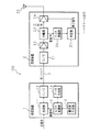
以下、本発明をその実施の形態を示す図面に基づいて説明する。図1は本発明に係る通信システム100を示す構成図である。通信システム100は、送信装置1、受信装置2、光ファイバ3などを備えている。送信装置1は、合成部11、E/O(電気/光変換器)12、搬送波生成部13、データ生成部14、ASK(Amplitude Shift Keying)変調部(振幅変調部)15などを備えている。受信装置2は、O/E(光/電気変換器)21、増幅器22、24、分離部23、ASK復調部26、判定部27などを備えている。なお、親局(又は放送局)及び子局(又は放送局)を光ファイバで接続して、無線信号、放送波信号などを中継する光中継システムの場合、親局及び子局(又は放送局)夫々には、送信装置1及び受信装置2を備えるような構成となる。
Hereinafter, the present invention will be described with reference to the drawings illustrating embodiments thereof. FIG. 1 is a block diagram showing a
通信システム100は、光ファイバ3を通じて、送受信する情報を有する主信号(例えば、2GHz帯域の携帯電話の無線信号)と、主信号の周波数帯域と異なる周波数帯域(例えば、315MHz帯域)の副信号とをアナログ光信号として伝送する光伝送システムである。
The
搬送波生成部13は、発振器を備え、例えば、315MHzの正弦波形の搬送波(無変調信号)を生成し、生成した搬送波をASK変調部15へ出力する。データ生成部14は、符号化回路などを備え、例えば、データレートが1kbpsのビット列(例えば、「1」、「0」など)で構成されるデータ信号を生成し、生成したデータ信号をASK変調部15へ出力する。データ信号としては、どのような形式、フォーマットのデータでもよく、エンコーダ(不図示)により予め定められた規則で符号化されている。
The
ASK変調部15は、広帯域オペアンプ、ミキサ(変調器)、ダイオードなどを備え、搬送波をデータ信号で変調し、変調して得られた副信号(変調信号)を合成部11へ出力する。より具体的には、例えば、ASK変調部15は、「1」のデータが入力されている間は、搬送波を出力し、「0」のデータが入力されている間は、搬送波の出力を停止することにより、副信号を生成する。
The
合成部11は、広帯域の合成器を備え、主信号と副信号とを合成し、合成した電気信号をE/O12へ出力する。なお、合成器に代えて共用器を用いる構成でもよい。
The
E/O12は、所定の波長帯のレーザ光を出力する半導体レーザを備え、合成部11から入力された電気信号(主信号と副信号との合成)を所定の波長帯の光信号に変換し、光ファイバ3を通じて、変換した光信号を受信装置2へ伝送する。
The E /
O/E21は、フォトダイオードを備え、光ファイバ3を通じて送信装置1から伝送された光信号を電気信号に変換し、変換した電気信号を増幅器22を介して分離部23へ出力する。
The O /
分離部23は、2GHz帯域の主信号を通過させるフィルタ、及び315MHz帯域の副信号を通過させるフィルタなどを組み合わせた共用器(デュプレクサ)を備え、O/E21から入力された電気信号を主信号と副信号とに分離する。分離部23は、分離した主信号を増幅器24へ出力するとともに、分離した副信号をASK復調部26へ出力する。なお、分離部23は、共用器に代えて、所要のフィルタ、分配器などを備える構成であってもよい。
The separation unit 23 includes a duplexer that combines a filter that passes the main signal in the 2 GHz band, a filter that passes the sub signal in the 315 MHz band, and the like, and the electrical signal input from the O /
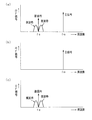
図2は主信号及び副信号の周波数スペクトラムの例を示す模式図である。図2(a)は合成部11で合成されE/O12に入力される主信号及び副信号(電気信号)を示す。図中fmは主信号の周波数であり、例えば、2GHz帯域であり、fsは副信号の周波数であり、例えば、315MHz帯域である。副信号は変調信号であり、fsの両側に側波帯が存在する。
FIG. 2 is a schematic diagram illustrating an example of the frequency spectrum of the main signal and the sub signal. FIG. 2A shows a main signal and a sub signal (electric signal) that are combined by the combining
図2(b)は分離部23で分離され増幅器24に入力される主信号を示し、図2(c)は分離部23で分離されASK復調部26に入力される副信号を示す。図に示すように、主信号と副信号との周波数間隔を広く(例えば、2GHzと315MHz)することにより、主信号と副信号との分離が容易になるとともに、主信号及び副信号を分離するためのフィルタ特性を簡略化することができ、フィルタの低コスト化、小型化を実現することができる。
2B shows the main signal separated by the separation unit 23 and inputted to the
増幅器24は、分離部23から入力された主信号を増幅し、増幅された主信号はアンテナ25を介して無線信号として送信される。
The
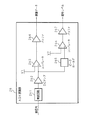
図3はASK復調部26の構成を示すブロック図である。ASK復調部26は、検波回路261、DCアンプ262、コンパレータ263、266、バッファ264、267、ピークホールド265、同期回路268などを備える。
FIG. 3 is a block diagram showing the configuration of the
検波回路261は、分離部23から入力された副信号をダイオード又は整流器などで半波又は両波整流して検波し、検波信号(DC信号)をDCアンプ262へ出力する。
The
DCアンプ262は、検波回路261から入力されたDC信号を増幅し、増幅したDC信号をコンパレータ263及びピークホールド265へ出力する。
The
コンパレータ263は、DCアンプ262から入力されたDC信号と基準電圧V1とを比較し、例えば、DC信号の電圧レベルが基準電圧V1より大きい場合には、ハイレベルの信号を出力し、DC信号の電圧レベルが基準電圧V1より小さい場合には、ローレベルの信号を出力することにより、DC信号を基準電圧V1に基づいてデータ信号を生成する。コンパレータ263は、生成したデータ信号をバッファ264へ出力する。
The
バッファ264は、コンパレータ263から入力されたデータ信号のレベル変換(電圧レベル変換)を行い、レベル変換されたデータ信号を同期回路268へ出力する。
The
同期回路268は、バッファ264から入力されたデータ信号からデータレート(例えば、1kbps)に従ってサンプリングのタイミング抽出を行い、1msec間隔でデータ信号をサンプリングして得られる復調データを判定部27へ出力する。
The
ピークホールド265は、DCアンプ262から入力されたDC信号の最大値(復調データのハイレベルに相当するレベル)を一定時間保持し、保持したホールド信号をコンパレータ266へ出力する。
The peak hold 265 holds the maximum value of the DC signal input from the DC amplifier 262 (a level corresponding to the high level of the demodulated data) for a predetermined time, and outputs the held signal to the
コンパレータ266は、ピークホールド265から入力されたホールド信号と基準電圧V2とを比較し、例えば、ホールド信号の電圧レベルが基準電圧V2より大きい場合には、ハイレベルの信号をバッファ267を介して判定部27へ出力し、ホールド信号の電圧レベルが基準電圧V2より小さい場合には、ローレベルの信号をバッファ267を介して判定部27へ出力する。
The
これにより、副信号の信号レベルは、ASK復調できる程度の信号レベルで足りるため、主信号に比較して十分に小さい信号レベル(例えば、−20dB程度)を用いることができ、光ファイバに送出できる主信号のレベルが制限されることがなく、送信装置で使用できる電気信号の大部分を主信号で占めることができる。 As a result, the signal level of the sub-signal is sufficient to enable ASK demodulation, so that a sufficiently low signal level (for example, about −20 dB) can be used as compared with the main signal, and the signal level can be sent to the optical fiber. The level of the main signal is not limited, and the main signal can occupy most of the electrical signals that can be used in the transmission apparatus.
図4はASK復調部26の各部の電圧波形の例を示す模式図である。図4(a)は検波回路261で検波された検波信号を示す。図4(b)は検波信号を基準電圧V1に基づいて二値化した二値化波形を示す。図に示すように、二値化波形のハイレベルは、データ「1」とし、二値化波形のローレベルは、データ「0」としてデータ信号が表される。さらに、データ信号は、図に示すように同期回路268において送信装置1で生成されるデータ信号のデータレートに合わせてサンプリングされ、復調データが生成される。また、図4(c)はピークホールド265でホールドされたホールド信号を示す。図4(d)は検波信号を基準電圧V2に基づいて二値化した副信号の信号レベルを示す。
FIG. 4 is a schematic diagram showing an example of the voltage waveform of each part of the
判定部27は、CPU、メモリ、デコーダなどを備え、ASK復調部26から入力された復調データ、及び副信号の信号レベルに基づいて、光ファイバ3における多重光反射の有無を判定し、これにより通信品質の劣化を検出する。判定部27は、光ファイバ3で生じた多重光反射による通信品質の劣化を検出した場合、これを報知するとともに、増幅器24へ停止信号を出力し、アンテナ25から主信号が送信されるのを停止する。
The determination unit 27 includes a CPU, a memory, a decoder, and the like, and determines the presence or absence of multiple light reflections in the
より具体的には、判定部27は、ASK復調部26から入力された復調データをデコーダで復号し、復号化されたデータが予め定められた元のデータと一致するか否かを判定する。判定部27は、復号化されたデータが元のデータと一致する場合には、多重光反射が発生していないと判定する。また、判定部27は、復号化されたデータが元のデータと一致しない場合には、多重光反射によるノイズの影響でデータの誤りが生じたとして、多重光反射が発生したと判定する。
More specifically, the determination unit 27 uses a decoder to decode the demodulated data input from the
また、判定部27は、ASK復調部26から入力された復調データに基づいて、多重光反射が発生したと判定した場合において、ASK復調部26から入力された副信号の信号レベルがハイレベルの信号であるときは、多重光反射の発生は正しい判定であるとして、最終的に多重光反射が発生したと判定する。
Further, when the determination unit 27 determines that multiple light reflection has occurred based on the demodulated data input from the
また、判定部27は、ASK復調部26から入力された復調データに基づいて、多重光反射が発生したと判定した場合において、ASK復調部26から入力された副信号の信号レベルがローレベルの信号であるときは、最終的に多重光反射以外の要因による異常が発生したと判定する。
In addition, when the determination unit 27 determines that multiple light reflection has occurred based on the demodulated data input from the
復調して得られた元のデータに誤りが生ずる要因として、光伝送路における多重光反射の他に、送信装置1のE/O12若しくは受信装置2のO/E21の故障、又は光回線の損失増加などにより、副信号の信号レベルの低下が想定される。受信装置2で分離した副信号の信号レベル(ホールド信号)を基準電圧V2と比較した比較結果に基づいて、多重光反射による異常の有無を判定する。例えば、信号レベルが基準電圧V2より小さい場合には、通信品質の劣化が多重光反射以外の要因によるものであると判定し、また、信号レベルが基準電圧V2より大きい場合には、通信品質の劣化が多重光反射以外の要因ではなく、多重光反射によるものであると判定する。これにより、多重光反射以外の要因による通信品質の劣化を層別して、さらに精度良く多重光反射による通信品質の劣化を判定することができる。
Possible causes of errors in the original data obtained by demodulation include failure of the E /
これにより、主信号の送受信を行いつつ多重光反射の発生を早期に検出することができるとともに、多重光反射が発生した場合には、他の通信チャネルへの影響を防止し、多重光反射に対する対応を迅速に行うことができる。 As a result, the occurrence of multiple light reflections can be detected at an early stage while transmitting / receiving the main signal, and when multiple light reflections occur, the influence on other communication channels can be prevented and It is possible to respond quickly.
次に本発明の通信システム100の動作について説明する。送信装置1は、主信号と副信号とを合成した電気信号を光信号に変換し、光ファイバ3を通じて、変換した光信号を受信装置2へ送信する。光ファイバ3などの光伝送路で多重光反射が発生した場合、伝送する光信号にガウス状のノイズが発生する。変調信号である副信号の場合には、副信号の側波帯に多重光反射によるノイズが生じる。
Next, the operation of the
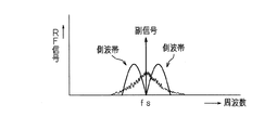
図5は多重光反射が発生した場合の副信号の周波数スペクトラムの例を示す模式図である。図に示すように、多重光反射が発生した場合、キャリアの周りにノイズが生ずる。 FIG. 5 is a schematic diagram showing an example of the frequency spectrum of the sub-signal when multiple light reflection occurs. As shown in the figure, when multiple light reflection occurs, noise is generated around the carrier.
受信装置2は、受信した光信号を電気信号に変換し、変換した電気信号を主信号と副信号とに分離する。側波帯に生じたノイズの影響により、分離された副信号を復調して得られたデータ信号には、誤りが生じる。
The receiving
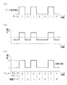
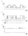
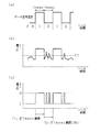
図6及び図7は多重光反射が発生の有無に応じたASK復調部26の検波信号の例を示す模式図である。図6(a)は送信装置1で生成されて送信されるデータ信号波形及びデータの例を示す。図の例では、データ(ビット列)は、「1」「0」「1」「0」「0」「1」「0」である。
6 and 7 are schematic diagrams showing examples of detection signals of the
図6(b)は多重光反射が発生していない場合の検波信号の例、図6(c)は多重光反射が発生していない場合のバッファ264の出力信号(二値化波形)の例である。多重光反射が発生していない場合、同期回路268でサンプリングする時点でノイズが重畳していないため、復調データは、「1」「0」「1」「0」「0」「1」「0」となり、送信されたデータと同一となる。
FIG. 6B shows an example of a detection signal when no multiple light reflection occurs, and FIG. 6C shows an example of an output signal (binarized waveform) of the
図7(a)は多重光反射が発生した場合の検波信号の例である。多重光反射が発生した場合、検波信号にノイズが重畳し、ローレベル(基準電圧V1以下)であるべき部分の波形が基準電圧V1より大きくなる。図7(b)は多重光反射が発生した場合のバッファ264の出力信号(二値化波形)の例である。同期回路268でサンプリングする時点でノイズにより検波信号の電圧レベルが基準電圧V1を超えた部分でデータに誤りが生じる。例えば、図7(b)に示すように、復調データは「1」「1」「1」「0」「0」「1」「1」となり、送信されたデータと異なる。図7(c)は副信号の信号レベルである。
FIG. 7A shows an example of a detection signal when multiple light reflection occurs. When multiple light reflection occurs, noise is superimposed on the detection signal, and the waveform of the portion that should be at a low level (reference voltage V1 or less) becomes larger than the reference voltage V1. FIG. 7B is an example of the output signal (binarized waveform) of the
判定部27は、ASK復調部26から入力された復調データが送信データと一致していない結果から多重光反射が発生したと判定し、さらに副信号の信号レベルがハイレベル信号であることから、最終的に光ファイバ3における多重光反射が発生していると判定し、通信品質の劣化を検出し、これを報知するとともに、増幅器24へ停止信号を出力し、アンテナ25から主信号が送信されるのを停止する。上述の実施の形態では、バッファ264の出力信号を同期回路268でサンプリングした復調データに基づいて、多重光反射の発生を判定するため、サンプリングポイントのみで判定することができ、簡便な処理で実現することができる。
The determination unit 27 determines that multiple light reflection has occurred based on the result that the demodulated data input from the
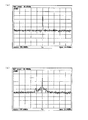
図8は伝送信号の周波数スペクトラムの例を示す模式図である。伝送信号(無変調波)の周波数は315MHz、光ファイバの長さを約10kmとした場合を示す。図8(a)は、多重光反射が発生していないときの周波数スペクトラムを示し、図8(b)は、多重光反射が発生しているときの周波数スペクトラムを示す。例えば、図に示すようなノイズのレベルと伝送信号(副信号)のレベルとの差が約20dB程度より小さい場合には、多重光反射の発生により通信品質の劣化が生じる可能性が高くなる。 FIG. 8 is a schematic diagram illustrating an example of a frequency spectrum of a transmission signal. The frequency of the transmission signal (unmodulated wave) is 315 MHz, and the length of the optical fiber is about 10 km. FIG. 8A shows a frequency spectrum when no multiple light reflection occurs, and FIG. 8B shows a frequency spectrum when multiple light reflection occurs. For example, when the difference between the level of noise and the level of the transmission signal (sub signal) as shown in the figure is less than about 20 dB, there is a high possibility that communication quality will deteriorate due to the occurrence of multiple light reflections.
実施の形態2
実施の形態1では、所定のビット列からなるデータ(例えば、判定データ)を有するデータ信号を用い、復調データが元のデータと一致するか否かに基づいて、多重光反射の発生を判定する構成であったが、これに限定されるものではなく、多重光反射の発生を判定するためには、判定データに代えてデータ信号のデータレートのみを用いる構成とすることもできる。
The first embodiment uses a data signal having data (for example, determination data) composed of a predetermined bit string, and determines the occurrence of multiple light reflection based on whether the demodulated data matches the original data. However, the present invention is not limited to this, and in order to determine the occurrence of multiple light reflections, it is possible to use only the data rate of the data signal instead of the determination data.
図9は実施の形態2のASK復調部26の構成を示すブロック図である。ASK復調部26は、検波回路261、DCアンプ262、コンパレータ263、266、バッファ264、267、ピークホールド265などを備え、実施の形態1との相違は、同期回路268を有しない点である。
FIG. 9 is a block diagram showing a configuration of the
検波回路261は、分離部23から入力された副信号をダイオード又は整流器などで半波又は両波整流して検波し、検波信号(DC信号)をDCアンプ262へ出力する。
The
DCアンプ262、コンパレータ263、バッファ264、ピークホールド265、コンパレータ266、バッファ267は実施の形態1と同様であるので、同一符号を付して説明を省略する。
Since the
図10は検波回路261で検波された検波信号の例を示す模式図である。図10(a)は副信号を検波回路261で検波して得られる検波信号である。図10(b)は検波信号を基準電圧V1に基づいて二値化した二値化波形を示す。図に示すように、二値化波形のハイレベルは、データ「1」とし、二値化波形のローレベルは、データ「0」としてデータ信号が表される。また、図10(c)はピークホールド265でホールドされたホールド信号を示す。図10(d)は検波信号を基準電圧V2に基づいて二値化した副信号の信号レベルを示す。
FIG. 10 is a schematic diagram illustrating an example of a detection signal detected by the
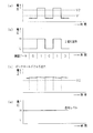
判定部27は、復調して得られたデータ信号のデータレートと送信時の所定のデータレートに基づいて、多重光反射の発生を判定する。より具体的には、送信時のデータレートが1kbpsである場合、復調データのオン状態(ハイレベル)、及びオフ状態(ローレベル)の継続時間が常に1msec±所定値(例えば、0.1msec)の範囲内であれば、多重光反射が発生していないと判定する。一方、副信号を復調して得られた復調データのオン状態(ハイレベル)、及びオフ状態(ローレベル)の継続時間が1msec±所定値(例えば、0.1msec)の範囲外であれば、多重光反射が発生したと判定する。 The determination unit 27 determines the occurrence of multiple light reflections based on the data rate of the data signal obtained by demodulation and a predetermined data rate at the time of transmission. More specifically, when the data rate at the time of transmission is 1 kbps, the duration time of the demodulated data in the on state (high level) and the off state (low level) is always 1 msec ± predetermined value (for example, 0.1 msec) If it is within the range, it is determined that multiple light reflection has not occurred. On the other hand, if the on-state (high level) and off-state (low level) duration of the demodulated data obtained by demodulating the sub signal is outside the range of 1 msec ± predetermined value (for example, 0.1 msec), It is determined that multiple light reflection has occurred.
図11は多重光反射が発生した場合のASK復調部26の検波信号の例を示す模式図である。図11(a)は送信装置1で生成されて送信されるデータ信号波形及びデータの例を示す。例えば、データ信号のデータレートは1kbpsであり、データが「1」及び「0」が交互に繰り返されるとともに、データが「1」及び「0」である時間が夫々1msecとなる。図の例では、データ(ビット列)は、「1」「0」「1」「0」である。
FIG. 11 is a schematic diagram showing an example of a detection signal of the
図11(b)は多重光反射が発生した場合の検波信号の例である。多重光反射が発生した場合、検波信号にノイズが重畳し、ローレベル(基準電圧V1以下)であるべき部分の波形が基準電圧V1より大きくなる。図11(c)に示すように、復調データは、ノイズにより検波信号の電圧レベルが基準電圧V1を超えた部分でハイレベル(「1」)となり、検波信号の電圧レベルが基準電圧V1以下の部分でローレベル(「0」)となる。すなわち、多重光反射の発生により、復調データの「0」の時間が約1msec間継続しない。 FIG. 11B shows an example of a detection signal when multiple light reflection occurs. When multiple light reflection occurs, noise is superimposed on the detection signal, and the waveform of the portion that should be at a low level (reference voltage V1 or less) becomes larger than the reference voltage V1. As shown in FIG. 11C, the demodulated data becomes high level (“1”) when the voltage level of the detection signal exceeds the reference voltage V1 due to noise, and the voltage level of the detection signal is equal to or lower than the reference voltage V1. It becomes a low level (“0”) in the part. That is, due to the occurrence of multiple light reflections, the time “0” of the demodulated data does not continue for about 1 msec.
判定部27は、復調データのハイレベル(「1」)の時間及びローレベル(「0」)の継続時間が、例えば、1msec±0.1msecの範囲内にあるか否かを判定する。図10(c)に示すように、判定部27は、まず、「1」の時間が約1msec間継続した後、「0」の時間が約1msec間継続すべきところ、「0」の時間が約1msec間継続しないことを検出することで、多重光反射が発生したことを判定する。 The determination unit 27 determines whether the high level (“1”) time and the low level (“0”) duration of the demodulated data are within a range of, for example, 1 msec ± 0.1 msec. As shown in FIG. 10 (c), the determination unit 27 first determines that the time “0” should continue for about 1 msec after the time “1” continues for about 1 msec. By detecting that it does not continue for about 1 msec, it is determined that multiple light reflection has occurred.
実施の形態1に比べて、復調データの「1」及び「0」の継続時間を検出することにより、多重光反射の発生によりノイズが検波信号に重畳する場合、ノイズが検波信号のいずれの部分に重畳してもノイズを検出することができ、多重光反射の発生を精度良く判定することができる。 Compared to the first embodiment, by detecting the durations of “1” and “0” of the demodulated data, when noise is superimposed on the detection signal due to the occurrence of multiple light reflection, any part of the detection signal is detected. Noise can be detected even when superimposed on the light, and the occurrence of multiple light reflection can be determined with high accuracy.
上述の実施の形態2では、復調データの「1」及び「0」の継続時間が1msec±所定値(例えば、0.1msec)の範囲内にあるか否かに基づいて、多重光反射の発生の有無を判定する構成であったが、これに限定されるものではなく、例えば、復調データの「1」及び「0」の時間を累積して加算して、復調データの「1」及び「0」の継続時間が1msecのn倍±所定値(例えば、0.1msec)の範囲内にあるか否かに基づいて、多重光反射の発生の有無を判定する構成であってもよい。ただし、nは自然数である。
In the second embodiment described above, multiple light reflections are generated based on whether or not the durations of demodulated data “1” and “0” are within a range of 1 msec ± predetermined value (for example, 0.1 msec). However, the present invention is not limited to this. For example, the times “1” and “0” of the demodulated data are accumulated and added to obtain “1” and “ The configuration may be such that the presence or absence of occurrence of multiple light reflections is determined based on whether or not the duration of “0” is in the range of
以上説明したように、本発明にあっては、副信号の高調波成分を用いる必要がなく、副信号のレベルを従来よりも小さくできるとともに、複雑なフィルタを構成することなく簡便な構成で多重光反射による通信品質の劣化を早期に検出することができる。また、副信号の信号レベルは、振幅復調できる程度の信号レベルで足りるため、主信号に比較して十分に小さく信号レベルを用いることができ、光ファイバに送出できる主信号のレベルが制限されることがなく、送信装置に入力される信号レベルの大部分を主信号で占めることができる。また、送信時のデータと受信時のデータの一致不一致に基づいて多重光反射による異常の有無を判定するため、多重光反射による通信品質の劣化を精度良く判定することができる。さらに、多重光反射以外の要因による通信品質の劣化を層別して、さらに精度良く多重光反射による通信品質の劣化を判定することができる。 As described above, in the present invention, it is not necessary to use the harmonic component of the sub-signal, the level of the sub-signal can be made smaller than before, and multiplexing can be performed with a simple configuration without forming a complex filter. It is possible to detect early deterioration of communication quality due to light reflection. Further, since the signal level of the sub signal is sufficient so that the amplitude can be demodulated, the signal level can be used sufficiently smaller than the main signal, and the level of the main signal that can be transmitted to the optical fiber is limited. The main signal can occupy most of the signal level input to the transmitter. Further, since the presence / absence of abnormality due to multiple light reflection is determined based on the mismatch between the data at the time of transmission and the data at the time of reception, it is possible to accurately determine deterioration in communication quality due to multiple light reflection. Further, it is possible to stratify communication quality deterioration due to factors other than multiple light reflection, and to determine communication quality deterioration due to multiple light reflection more accurately.
上述の実施の形態においては、主信号の周波数を2GHz、副信号の周波数を315MHzとして説明したが、周波数帯域はこれに限定されるものではなく、所要の主信号及び該主信号と周波数の異なる副信号を使用することができる。 In the above-described embodiment, the frequency of the main signal is 2 GHz and the frequency of the sub signal is 315 MHz. However, the frequency band is not limited to this, and the required main signal and the frequency differ from the main signal. Side signals can be used.
上述の実施の形態では、送信装置1から受信装置2へ主信号及び副信号を送信する場合について説明したが、本発明は、上り方向及び下り方向の双方向に光信号を伝送する光伝送システムにも適用することができる。例えば、上り方向と下り方向とで主信号の周波数が異なる場合、主信号夫々の周波数と異なるとともに、相互に異なる周波数の上り方向用の副信号及び下り方向用の副信号を用いることができる。
In the above-described embodiment, the case where the main signal and the sub signal are transmitted from the
上述の実施の形態においては、多重光反射により異常と判定した場合、受信装置2でアンテナ25を介して主信号の送信を停止する構成であったが、これに限定されるものではなく、送信装置1に多重光反射の判定結果を送信し、送信装置1で主信号の送信を停止させるようにしてもよい。
In the above-described embodiment, when it is determined that there is an abnormality due to multiple light reflection, the
上述の実施の形態においては、振幅変調方式を用いる構成であったが、変調方式はこれに限定されるものではなく、他の変調方式、例えば、周波数変調方式、位相変調方式などを用いる構成であってもよい。なお、振幅変調方式を採用した場合には、ノイズによる影響を受け易いため、他の変調方式に比べて精度良く多重光反射の発生の有無を判定することができる。 In the above-described embodiment, the configuration using the amplitude modulation method is used. However, the modulation method is not limited to this, and other modulation methods such as a frequency modulation method and a phase modulation method are used. There may be. When the amplitude modulation method is adopted, it is easy to be influenced by noise, and therefore it is possible to determine the presence / absence of the occurrence of multiple light reflection with higher accuracy than other modulation methods.
1 送信装置
2 受信装置
3 光ファイバ
11 合成部
12 E/O
13 搬送波生成部
14 データ生成部
15 ASK変調部
21 O/E
22、24 増幅器
23 分離部
26 ASK復調部
27 判定部
261 検波回路
262 DCアンプ
263、266 コンパレータ
264、267 バッファ
265 ピークホールド
268 同期回路
DESCRIPTION OF
13
22, 24 Amplifier 23
Claims (4)
前記送信装置は、
搬送波を所定のデータレートを有するデータ信号で変調した副信号を生成する変調手段と、
送受信する情報を有する主信号と前記副信号とを合成する合成手段と、
該合成手段が合成した電気信号を光信号に変換する変換手段と
を備え、
前記受信装置は、
受信した光信号を電気信号に変換する変換手段と、
該変換手段で変換された電気信号を主信号と副信号とに分離する分離手段と、
該分離手段で分離された副信号を復調する復調手段と、
該復調手段で復調して得られたデータ信号のデータレート及び前記所定のデータレートに基づいて、光ファイバを通じて送受信される光信号の多重光反射を判定する手段と
を備えることを特徴とする通信システム。 A transmission device that converts an electrical signal into an optical signal, transmits the converted optical signal through an optical fiber, and a reception device that receives the optical signal transmitted by the transmission device and converts the received optical signal into an electrical signal. In a communication system,
The transmitter is
Modulation means for generating a sub-signal obtained by modulating a carrier wave with a data signal having a predetermined data rate;
Combining means for combining the main signal having information to be transmitted and received and the sub-signal;
Conversion means for converting the electrical signal synthesized by the synthesis means into an optical signal,
The receiving device is:
Conversion means for converting the received optical signal into an electrical signal;
Separating means for separating the electric signal converted by the converting means into a main signal and a sub-signal;
Demodulating means for demodulating the sub-signal separated by the separating means;
Means for determining multiple light reflections of an optical signal transmitted / received through an optical fiber based on a data rate of a data signal obtained by demodulation by the demodulating means and the predetermined data rate. system.
振幅変調方式で変調するように構成してあることを特徴とする請求項1に記載の通信システム。 The modulating means includes
The communication system according to claim 1, wherein the communication system is configured to perform modulation using an amplitude modulation method.
所定のデータを有するデータ信号で搬送波を変調するように構成してあり、
前記復調手段で復調して得られたデータ信号のデータが前記所定のデータと異なる場合、多重光反射による異常と判定する手段を備えることを特徴とする請求項1又は請求項2に記載の通信システム。 The modulating means includes
It is configured to modulate a carrier wave with a data signal having predetermined data,
3. The communication according to claim 1, further comprising means for determining that an abnormality is caused by multiple light reflection when data of a data signal obtained by demodulating by the demodulating means is different from the predetermined data. system.
該検出手段で検出された信号レベルを所定の信号閾値と比較する比較手段と、
該比較手段の比較結果に基づいて、多重光反射による異常の有無を判定する手段と
を備えることを特徴とする請求項1乃至請求項3のいずれかに記載の通信システム。 Detecting means for detecting a signal level of the sub signal separated by the separating means;
Comparing means for comparing the signal level detected by the detecting means with a predetermined signal threshold;
The communication system according to any one of claims 1 to 3, further comprising: a unit that determines presence / absence of abnormality due to multiple light reflection based on a comparison result of the comparison unit.
Priority Applications (1)
| Application Number | Priority Date | Filing Date | Title |
|---|---|---|---|
| JP2006104566A JP2007281817A (en) | 2006-04-05 | 2006-04-05 | Communication system |
Applications Claiming Priority (1)
| Application Number | Priority Date | Filing Date | Title |
|---|---|---|---|
| JP2006104566A JP2007281817A (en) | 2006-04-05 | 2006-04-05 | Communication system |
Publications (1)
| Publication Number | Publication Date |
|---|---|
| JP2007281817A true JP2007281817A (en) | 2007-10-25 |
Family
ID=38682821
Family Applications (1)
| Application Number | Title | Priority Date | Filing Date |
|---|---|---|---|
| JP2006104566A Pending JP2007281817A (en) | 2006-04-05 | 2006-04-05 | Communication system |
Country Status (1)
| Country | Link |
|---|---|
| JP (1) | JP2007281817A (en) |
Cited By (1)
| Publication number | Priority date | Publication date | Assignee | Title |
|---|---|---|---|---|
| WO2023167046A1 (en) * | 2022-03-01 | 2023-09-07 | 住友電気工業株式会社 | Optical communication system, master station device, slave station device, and optical communication method |
-
2006
- 2006-04-05 JP JP2006104566A patent/JP2007281817A/en active Pending
Cited By (1)
| Publication number | Priority date | Publication date | Assignee | Title |
|---|---|---|---|---|
| WO2023167046A1 (en) * | 2022-03-01 | 2023-09-07 | 住友電気工業株式会社 | Optical communication system, master station device, slave station device, and optical communication method |
Similar Documents
| Publication | Publication Date | Title |
|---|---|---|
| US9614696B2 (en) | Alternating phase filter for increasing communication speeds, spectral efficiency and enabling other benefits | |
| CN106134108B (en) | Decoding combined amplitude and frequency modulated signals | |
| JP2008022340A (en) | Multimode receiving circuit | |
| JP2006352848A (en) | Light signal transmission device and signal processing method | |
| WO2022013572A2 (en) | Long range ambient backscatter apparatus | |
| US11418255B2 (en) | Method, device and system for controlling protection switching on optical network | |
| JP2007281817A (en) | Communication system | |
| JP4901497B2 (en) | Communication system, transmitter, receiver, communication method, transmitter detection method, communication procedure setting method | |
| US20040214603A1 (en) | Control station apparatus base station apparatus and optical transmission method | |
| JP3218325B2 (en) | Millimeter-wave wireless / optical fiber transmission system and equipment | |
| JP3863463B2 (en) | Signal transmission method and signal transmission system | |
| US20040136454A1 (en) | System and method for digital transmission and modulation of conjugate pulse position | |
| WO2022162818A1 (en) | Wireless communication system, wireless communication method, transmission-side system, and reception-side system | |
| JP4469786B2 (en) | Optical signal transmission apparatus and signal processing method | |
| JP2007329677A (en) | Optical relay transmission apparatus, and signal processing method | |
| KR101165539B1 (en) | Apparatus and method for additional data inserted broadcasting signal transmission and reception and broadcasting signal transmission and reception system | |
| JP2007036751A (en) | Optical signal transmitter and optical signal receiver | |
| JP2005323145A (en) | Communications system, and transmission station, receiving station and communication method thereof | |
| JP2006254178A (en) | Base station device and control station device | |
| JP2007329888A (en) | Optical relay transmission apparatus, and signal processing method | |
| US20120064821A1 (en) | System and Method for Identifying the Path or Devices on the Path of a Communication Signal Using (1+r(T)) Amplitude Modulation | |
| JPH0746255A (en) | Transmitter-receiver | |
| JP2003051788A (en) | Optical transmitter | |
| JP2005354464A (en) | Digital radio communication system and communication control method thereof | |
| JP2008211279A (en) | Radio communication system |