JP2007281069A - Casing for portable terminal equipment - Google Patents
Casing for portable terminal equipment Download PDFInfo
- Publication number
- JP2007281069A JP2007281069A JP2006103084A JP2006103084A JP2007281069A JP 2007281069 A JP2007281069 A JP 2007281069A JP 2006103084 A JP2006103084 A JP 2006103084A JP 2006103084 A JP2006103084 A JP 2006103084A JP 2007281069 A JP2007281069 A JP 2007281069A
- Authority
- JP
- Japan
- Prior art keywords
- casing
- resin
- hole
- terminal device
- portable terminal
- Prior art date
- Legal status (The legal status is an assumption and is not a legal conclusion. Google has not performed a legal analysis and makes no representation as to the accuracy of the status listed.)
- Pending
Links
- 239000002184 metal Substances 0.000 claims abstract description 57
- 239000011347 resin Substances 0.000 claims abstract description 43
- 229920005989 resin Polymers 0.000 claims abstract description 43
- 238000000465 moulding Methods 0.000 claims description 16
- 239000007769 metal material Substances 0.000 claims description 5
- 238000000034 method Methods 0.000 description 4
- OKTJSMMVPCPJKN-UHFFFAOYSA-N Carbon Chemical compound [C] OKTJSMMVPCPJKN-UHFFFAOYSA-N 0.000 description 2
- 229910052799 carbon Inorganic materials 0.000 description 2
- 239000000843 powder Substances 0.000 description 2
- 230000005540 biological transmission Effects 0.000 description 1
- 238000000151 deposition Methods 0.000 description 1
- 238000010586 diagram Methods 0.000 description 1
- 238000005516 engineering process Methods 0.000 description 1
- 238000004519 manufacturing process Methods 0.000 description 1
- 230000035945 sensitivity Effects 0.000 description 1
Images

Landscapes
- Telephone Set Structure (AREA)
- Casings For Electric Apparatus (AREA)
Abstract
Description
本発明は携帯端末機器の筐体に関し、特に剛性に優れた携帯端末機器の筐体に関する。 The present invention relates to a casing of a mobile terminal device, and more particularly to a casing of a mobile terminal device having excellent rigidity.
携帯端末機器の筐体は上面部及び底面部からなり、この上面部及び底面部をネジ等によって締結することで構成される。携帯端末機器の筐体は金属及び/又は樹脂を成型することによって作成される。携帯端末機器の筐体を樹脂によって作成する場合、電磁的シールドを確保するためにカーボン又は金属粉等を混入させた樹脂によって筐体を作成する方法が考えられる。また、電磁的シールド及び電気的なグランドを確保し、外部からの衝撃に対する耐性を上げるために、樹脂によって筐体を作成し、この筐体の内面に金属を蒸着する方法も考えられる。しかしながら、樹脂にカーボン又は金属粉等を混入させると樹脂自体の強度が低下するという問題点がある。また、携帯端末機器の筐体を樹脂のみによって作成すると、成型の際に成型用金型内に溶融樹脂の流動性を確保するため、所定の必要最低限度の板厚が必要になり、薄型化が難しいという問題点もある。 The casing of the portable terminal device includes an upper surface portion and a bottom surface portion, and is configured by fastening the upper surface portion and the bottom surface portion with screws or the like. The casing of the portable terminal device is created by molding metal and / or resin. In the case where the casing of the mobile terminal device is made of resin, there can be considered a method of making the casing of a resin mixed with carbon or metal powder in order to secure an electromagnetic shield. Further, in order to secure an electromagnetic shield and an electric ground and to increase resistance to external impact, a method of creating a casing with resin and depositing metal on the inner surface of the casing is also conceivable. However, when carbon or metal powder is mixed in the resin, there is a problem that the strength of the resin itself is lowered. In addition, if the casing of the portable terminal device is made of resin only, the required minimum thickness is required to ensure the fluidity of the molten resin in the molding die during molding, making it thinner. There is also a problem that is difficult.
この問題点を解決すべく、特許文献1に開示された電子機器の筐体は、外側部が金属によって形成され、外側部の内部に配置される内側部が金属又は樹脂によって形成され、これらの外側部及び内側部によって筐体が構成されている。しかしながら、電子機器の筐体の外側部及び内側部が金属によって形成されると、電子機器が送受信用のアンテナを内蔵している場合は、このアンテナの感度を低下させてしまうという問題点がある。
In order to solve this problem, the casing of the electronic device disclosed in
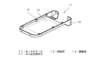
また、金属板と樹脂とを一体成型することによって携帯端末機器の筐体の内側部を金属、外側部を樹脂で形成する技術が開示されている(例えば特許文献2及び3)。これにより、携帯端末機器の筐体の薄型化、剛性及び電気特性の向上を図っている。特許文献2及び3に開示された技術における携帯端末機器の筐体において、数字キー側筐体の上面部を裏側から見た状態を示す模式的斜視図である。図3に示すように、インサート成型等によって樹脂部14と板金部12とが一体成型され、モールドケース11が形成されている。モールドケース11の内部にはネジ止め用ボス17が複数個設けられている。ネジ止め用ボス17は、板金部12と成型用樹脂とを一体成型する際に成型用樹脂によって設けられている。
Moreover, the technique which forms the inner part of the housing | casing of a portable terminal device with a metal, and forms an outer part with resin by integrally forming a metal plate and resin is disclosed (for example,
そして、モールドケース11とモールドケース11を覆設する形状を有するボトムケース(図示せず)とが対向して重ね合わされ、ネジ(図示せず)によってボトムケース(図示せず)に設けられた貫通孔の外観側からモールドケース11に設けられたネジ止め用ボス17にネジ締めが行われることによってモールドケース11とボトムケース(図示せず)とが締結されるというものである。
Then, a
しかしながら、上述の特許文献2及び3に開示された携帯端末機器の筐体並びに特許文献1において、外側部が金属によって形成され、内側部が樹脂によって形成された電子機器の筐体は、ネジ止め用ボス17が樹脂製であるため、ネジ締めの際にネジ空転が起こったり、筐体に外部から衝撃が加わったときにネジ締結部が破損したりする等の問題点がある。これらの問題点を解決するためにネジ止め用ボス17にインサートナットを入れる必要があり、このため組み立て工数が増加し、また部品が増加するため筐体が軽量化できないという問題点がある。
However, in the case of the portable terminal device disclosed in
本発明はかかる問題点に鑑みてなされたものであって、筐体の上面部と底面部とをネジ締めによって締結する際に、部品数及び組み立て工数を削減でき、軽量で剛性の高い携帯端末機器の筐体を提供することを目的とする。 The present invention has been made in view of such a problem, and when fastening the upper surface portion and the bottom surface portion of the housing by screw tightening, the number of components and the number of assembly steps can be reduced, and the portable terminal is lightweight and highly rigid. The object is to provide a housing for the device.
本発明に係る携帯端末機器の筐体は、内側部が金属、外側部が樹脂で形成され前記金属に穴を有する板金絞り部が形成された上面部と、内側部が金属、外側部が樹脂で形成され前記穴に対応する部位に貫通孔を有する底面部と、を有し、前記貫通孔の外観側から前記穴に対してネジ締めを行うことによって前記上面部と前記底面部とが締結されることを特徴とする。筐体の金属部に形成された穴に対してネジ締めを行うことにより、従来技術において樹脂製のネジ止め用ボスに対してネジ締めを行うよりも剛性を向上させることができ、また、インサートナットが不要になるため部品数が減少し、軽量化でき、また組み立て工数を削減することができる。 The casing of the portable terminal device according to the present invention has an upper surface formed with a sheet metal drawing portion having an inner portion made of metal and an outer portion made of resin and having a hole in the metal, an inner portion made of metal, and an outer portion made of resin. A bottom surface portion having a through hole at a portion corresponding to the hole, and the top surface portion and the bottom surface portion are fastened by screwing the hole from the exterior side of the through hole. It is characterized by being. By tightening the screw in the hole formed in the metal part of the housing, the rigidity can be improved compared to the case of screwing the screw boss made of resin in the prior art. Since nuts are not required, the number of parts can be reduced, the weight can be reduced, and the number of assembly steps can be reduced.
前記上面部及び前記底面部は、金属材と成形用樹脂とが一体成型されて形成されていることが好ましい。これにより、金属と樹脂とを接着するよりも剛性及び耐久性に優れ、樹脂の成形容易性及び可撓性等と金属の剛性及び耐熱性等を組み合わせ、相互補完することで薄型化及び加工の精巧化が可能になる。 It is preferable that the upper surface portion and the bottom surface portion are formed by integrally molding a metal material and a molding resin. As a result, it is superior in rigidity and durability compared to bonding metal and resin, and it is possible to reduce the thickness and process by combining and complementing the resin moldability and flexibility with the metal rigidity and heat resistance. Sophistication is possible.
前記底面部の一部が金属によって形成されていてもよい。
また、前記底面部は、金属材と成形用樹脂とが一体成型されて形成されていてもよい。これにより筐体の剛性を向上させることができ、また、底面部を全て樹脂によって形成するよりも底面部の厚さを小さくできることができるため、携帯端末機器の筐体の厚さを低減することができる。
A part of the bottom portion may be formed of metal.
Further, the bottom surface portion may be formed by integrally molding a metal material and a molding resin. As a result, the rigidity of the housing can be improved, and the thickness of the bottom surface portion can be made smaller than when the bottom surface portion is entirely made of resin, so the thickness of the housing of the portable terminal device can be reduced. Can do.
前記穴がネジ止め用の穴であってもよい。 The holes may be screw holes.
また、前記穴がバーリング加工によって設けられていてもよい。これにより、バーリングに対してネジ締めを行う場合は、ネジ止め用の穴に対してネジ締めを行う場合よりも、ネジの噛み込み量が少なくてよいため、板金絞り部の高さを低くすることができ、携帯端末機器の筐体厚さを低減させることができる。 Moreover, the hole may be provided by burring. As a result, when the screw is tightened on the burring, the amount of screw biting may be smaller than when the screw is tightened on the screw fixing hole, so that the height of the sheet metal restricting portion is lowered. And the thickness of the casing of the mobile terminal device can be reduced.
前記ネジ締めがタップタイトにより行われてもよい。これにより、板金絞り部に下穴を形成すれば、タップタイトで上面部と下面部とを締結するときに雌ネジ加工とネジ締めとを同時に行うことができ、組み立て工数を低減することができる。 The screw tightening may be performed by tap tight. Thereby, if a pilot hole is formed in a sheet metal drawing part, female screw processing and screw tightening can be performed at the same time when the upper surface part and the lower surface part are fastened with tap tight, and the number of assembly steps can be reduced. .
本発明によれば、携帯端末機器の筐体の上面部と底面部とをネジ締めによって締結する際に金属部に対しネジ締めを行うことにより、従来技術において樹脂製のネジ止め用ボスにインサートナットを挿入し、これに対してネジ締めを行うよりも剛性を向上させることができる。また、インサートナットが不要であるため部品数が減少し、軽量化でき、組み立て工数を削減することができる。 According to the present invention, when the upper surface portion and the bottom surface portion of the casing of the mobile terminal device are tightened by screw tightening, the metal portion is screwed to insert the resin screw fixing boss in the prior art. Rigidity can be improved compared to inserting a nut and tightening a screw on the nut. Moreover, since an insert nut is unnecessary, the number of parts can be reduced, the weight can be reduced, and the number of assembly steps can be reduced.
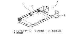
次に、本発明の実施形態について、添付の図面を参照して具体的に説明する。図1は本発明の第1実施形態に係る携帯端末機器の筐体において、数字キー側筐体の上面部を裏側から見た状態を示す模式的斜視図である。金属材としての板金部2と成形用樹脂とがインサート成型等によって一体成型され、上面部としてのモールドケース1が形成されている。モールドケース1において、外側部としての樹脂部4は凹形状を有しており、底面に矩形の開口部が設けられている。樹脂部4の凹部底面には内側部としての板金部2が嵌め込まれ、板金部2には樹脂部4の4隅を含む長手方向の辺に複数個の板金絞り部3が設けられ、板金部2の周囲が樹脂部4で覆われるように構成されている。また、樹脂部4の底面に設けられた矩形の開口部から板金部2が外部に露出している。板金絞り部3は板金部2の一部であり、板金部2を絞り加工することで形成され、板金絞り部3には穴としてネジ止め用の穴が設けられている。
Next, embodiments of the present invention will be specifically described with reference to the accompanying drawings. FIG. 1 is a schematic perspective view showing a state in which a top surface portion of a numeric key side casing is viewed from the back side in the casing of the portable terminal device according to the first embodiment of the present invention. A
図2は本発明の第1実施形態に係る携帯端末機器の筐体において、数字キー側筐体の底面部(ボトムケース6)と上面部(モールドケース1)とを締結する状態を示す模式的斜視図である。ボトムケース6はモールドケース1を覆設する形状を有し、モールドケース1の板金絞り部3に設けられたネジ止め用の穴に対応する部位に貫通孔が設けられている。ボトムケース6に設けられた貫通孔から板金絞り部3に設けられたネジ止め用の穴にネジ5がネジ締めされることにより、モールドケース1とボトムケース6とが締結される。
FIG. 2 is a schematic diagram showing a state in which the bottom surface portion (bottom case 6) and the top surface portion (mold case 1) of the number key side housing are fastened in the housing of the mobile terminal device according to the first embodiment of the present invention. It is a perspective view. The bottom case 6 has a shape covering the
次に、上述の如く構成された本実施形態に係る携帯端末機器の筐体の動作について説明する。モールドケース1とボトムケース6とを対向させて重ね合わせ、ネジ5をボトムケース6の貫通孔の外観面側から挿入し、板金絞り部3に設けられたネジ止め用の穴にネジ締めを行う。これにより、モールドケース1とボトムケース6とを締結する。
Next, the operation of the casing of the portable terminal device according to the present embodiment configured as described above will be described. The
従来技術においてモールドケース11の樹脂部11に設けられた樹脂製のネジ止め用ボス17にネジ締めを行う場合、剛性を向上させるためにインサートナットを挿入する必要があるが、本実施形態においてはネジ止め用の穴が板金絞り部3に設けられているため、インサートナットは不要であり、部品数を低減することができる。また、ネジ止め締結部が全て金属によって形成されているため、樹脂製のネジ止め用ボス17にネジ締めを行うよりも剛性が向上する。
In the prior art, when the screw fastening
次に、本発明の第2実施形態について説明する。本実施形態においてはボトムケース6が、第1実施形態におけるモールドケース1と同様、外側部を樹脂、内側部を金属で一体成型されている。これにより、ボトムケース6の厚さを小さくできることによって携帯端末機器の筐体の厚さを低減することができ、筐体の剛性を向上させることができる。
Next, a second embodiment of the present invention will be described. In the present embodiment, the bottom case 6 is integrally formed of a resin on the outer side and a metal on the inner side, like the
次に、本発明の第3実施形態について説明する。上述の第1実施形態は板金絞り部3にネジ止め用の穴が設けられているのに対し、本実施形態においては板金絞り部3にバーリング加工が施されており、それ以外は第1実施形態と同様の構造を有している。
Next, a third embodiment of the present invention will be described. In the first embodiment described above, a screw-fastening hole is provided in the sheet
板金絞り部3にバーリング加工が施され、これによって設けられた穴にネジ止めを行う場合、ネジ止め用の穴にネジ止めを行う場合よりもネジの噛み込み量が少なくてよい。これにより板金絞り部3の高さを低くすることができるため、携帯端末機器の筐体厚さを低減させることができる。
When the burring process is performed on the sheet
次に、本発明の第4実施形態について説明する。上述の第1実施形態は板金絞り部3にネジ止め用の穴が設けられ、モールドケース1とボトムケース6とがネジ5によって締結されているのに対し、本実施形態においてはモールドケース1とボトムケース6とをタップタイトによって締結する点で異なり、それ以外は第1実施形態と同様の構造を有している。
Next, a fourth embodiment of the present invention will be described. In the first embodiment described above, a screw-fastening hole is provided in the sheet
タップタイトによってモールドケース1とボトムケース6とを締結する場合、板金部2に設けられた板金絞り部3に下穴を設ければ、タップタイトでモールドケース1とボトムケース6とを締結するときに雌ネジ加工とネジ締めとを同時に行うことができ、組み立て工数を低減することができる。
When the
上述のように、本発明によれば、筐体の上面部と底面部とをネジ締めによって締結する際に、金属部に対しネジ締めを行うことにより、従来技術において樹脂製のネジ止め用ボスにネジ締めを行うよりも剛性を向上させることができ、またインサートナットが不要になるため部品数が減少し、軽量化でき、また組み立て工数を削減でき、剛性の高い携帯端末機器の筐体が得られる。 As described above, according to the present invention, when the upper surface portion and the bottom surface portion of the casing are fastened by screw tightening, the screw tightening boss made of resin in the prior art is performed by screwing the metal portion. It is possible to improve the rigidity compared to screw tightening, and since the insert nut is not required, the number of parts can be reduced, the weight can be reduced, the number of assembly steps can be reduced, and a highly rigid portable terminal device housing can be obtained. can get.
1 ; モールドケース
2 ; 板金部
3 ; 板金絞り部
4 ; 樹脂部
5 ; ネジ
6 ; ボトムケース
11 ; モールドケース
12 ; 板金部
14 ; 樹脂部
17 ; ネジ止め用ボス
DESCRIPTION OF
Claims (7)
The case of the mobile terminal device according to any one of claims 1 to 4, wherein the screw tightening is performed by tap tight.
Priority Applications (1)
| Application Number | Priority Date | Filing Date | Title |
|---|---|---|---|
| JP2006103084A JP2007281069A (en) | 2006-04-04 | 2006-04-04 | Casing for portable terminal equipment |
Applications Claiming Priority (1)
| Application Number | Priority Date | Filing Date | Title |
|---|---|---|---|
| JP2006103084A JP2007281069A (en) | 2006-04-04 | 2006-04-04 | Casing for portable terminal equipment |
Publications (1)
| Publication Number | Publication Date |
|---|---|
| JP2007281069A true JP2007281069A (en) | 2007-10-25 |
Family
ID=38682236
Family Applications (1)
| Application Number | Title | Priority Date | Filing Date |
|---|---|---|---|
| JP2006103084A Pending JP2007281069A (en) | 2006-04-04 | 2006-04-04 | Casing for portable terminal equipment |
Country Status (1)
| Country | Link |
|---|---|
| JP (1) | JP2007281069A (en) |
Cited By (2)
| Publication number | Priority date | Publication date | Assignee | Title |
|---|---|---|---|---|
| KR20120045763A (en) * | 2010-11-01 | 2012-05-09 | 삼성전자주식회사 | Portable terminal |
| WO2013136398A1 (en) | 2012-03-12 | 2013-09-19 | 日本電気株式会社 | Portable terminal device |
-
2006
- 2006-04-04 JP JP2006103084A patent/JP2007281069A/en active Pending
Cited By (3)
| Publication number | Priority date | Publication date | Assignee | Title |
|---|---|---|---|---|
| KR20120045763A (en) * | 2010-11-01 | 2012-05-09 | 삼성전자주식회사 | Portable terminal |
| KR101695989B1 (en) | 2010-11-01 | 2017-01-13 | 삼성전자주식회사 | Portable terminal |
| WO2013136398A1 (en) | 2012-03-12 | 2013-09-19 | 日本電気株式会社 | Portable terminal device |
Similar Documents
| Publication | Publication Date | Title |
|---|---|---|
| US8338703B2 (en) | Housing for an electronic device, device comprising such a housing and method for manufacturing such a housing | |
| US10398021B2 (en) | Housing for an electronic control unit and method of manufacture | |
| JP3213707U (en) | Control device for electric power steering | |
| JP2017157769A (en) | Resin-sealed in-vehicle controller | |
| US20150264831A1 (en) | Casing assembly and power supply apparatus with the same | |
| JP3139061U (en) | USB connector metal housing structure | |
| US8081466B2 (en) | Overmolded electronics enclosure | |
| JP2008256296A (en) | Air conditioner outdoor unit | |
| JP2007281069A (en) | Casing for portable terminal equipment | |
| JP2009231472A (en) | Electronic apparatus | |
| US12127358B2 (en) | Middle frame, electronic device, and method for manufacturing middle frame | |
| JP4122460B2 (en) | Disc device integrated liquid crystal display device | |
| JP2008251911A (en) | Housing mounting structure | |
| US20110033657A1 (en) | Metal shell manufacturing structure and method | |
| US20100034416A1 (en) | Receiving structure for speaker | |
| KR101966256B1 (en) | Assembling structure of housing for portable terminal | |
| JP5716647B2 (en) | Electronic equipment | |
| US8674248B2 (en) | Input key and manufacturing method thereof | |
| JP2008279847A (en) | Electronic equipment | |
| JP3678629B2 (en) | Notebook information processor | |
| JP2005093905A (en) | Electronic board unit | |
| JP2011187844A (en) | Electronic device, and shield member | |
| CN203801207U (en) | Mobile terminal with shielding structure | |
| JP4863954B2 (en) | Electronic unit and manufacturing method thereof | |
| US11503722B2 (en) | Enclosure for power supply circuit board and power supply unit |
Legal Events
| Date | Code | Title | Description |
|---|---|---|---|
| RD04 | Notification of resignation of power of attorney |
Free format text: JAPANESE INTERMEDIATE CODE: A7424 Effective date: 20080625 |