JP2007279669A - Fixing device, image forming apparatus, and fixing nip forming method of fixing device - Google Patents
Fixing device, image forming apparatus, and fixing nip forming method of fixing device Download PDFInfo
- Publication number
- JP2007279669A JP2007279669A JP2006283310A JP2006283310A JP2007279669A JP 2007279669 A JP2007279669 A JP 2007279669A JP 2006283310 A JP2006283310 A JP 2006283310A JP 2006283310 A JP2006283310 A JP 2006283310A JP 2007279669 A JP2007279669 A JP 2007279669A
- Authority
- JP
- Japan
- Prior art keywords
- fixing
- support member
- fixing device
- layer
- heat generating
- Prior art date
- Legal status (The legal status is an assumption and is not a legal conclusion. Google has not performed a legal analysis and makes no representation as to the accuracy of the status listed.)
- Pending
Links
Images


Classifications
-
- G—PHYSICS
- G03—PHOTOGRAPHY; CINEMATOGRAPHY; ANALOGOUS TECHNIQUES USING WAVES OTHER THAN OPTICAL WAVES; ELECTROGRAPHY; HOLOGRAPHY
- G03G—ELECTROGRAPHY; ELECTROPHOTOGRAPHY; MAGNETOGRAPHY
- G03G15/00—Apparatus for electrographic processes using a charge pattern
- G03G15/20—Apparatus for electrographic processes using a charge pattern for fixing, e.g. by using heat
- G03G15/2003—Apparatus for electrographic processes using a charge pattern for fixing, e.g. by using heat using heat
- G03G15/2014—Apparatus for electrographic processes using a charge pattern for fixing, e.g. by using heat using heat using contact heat
- G03G15/206—Structural details or chemical composition of the pressure elements and layers thereof
-
- G—PHYSICS
- G03—PHOTOGRAPHY; CINEMATOGRAPHY; ANALOGOUS TECHNIQUES USING WAVES OTHER THAN OPTICAL WAVES; ELECTROGRAPHY; HOLOGRAPHY
- G03G—ELECTROGRAPHY; ELECTROPHOTOGRAPHY; MAGNETOGRAPHY
- G03G2215/00—Apparatus for electrophotographic processes
- G03G2215/00135—Handling of parts of the apparatus
- G03G2215/00139—Belt
- G03G2215/00143—Meandering prevention
- G03G2215/00151—Meandering prevention using edge limitations
-
- G—PHYSICS
- G03—PHOTOGRAPHY; CINEMATOGRAPHY; ANALOGOUS TECHNIQUES USING WAVES OTHER THAN OPTICAL WAVES; ELECTROGRAPHY; HOLOGRAPHY
- G03G—ELECTROGRAPHY; ELECTROPHOTOGRAPHY; MAGNETOGRAPHY
- G03G2215/00—Apparatus for electrophotographic processes
- G03G2215/20—Details of the fixing device or porcess
Abstract
Description
この発明は、複写機、プリンタ、ファクシミリまたはそれらの複合機などの画像形成装置に関する。特に、感光体上に形成したトナー画像を転写して、用紙やOHPフィルムなどの記録材上に画像を記録する電子写真式の画像形成装置に関する。および、そのような画像形成装置などに備えて、定着ニップに記録材を通して熱と圧力とを加え、トナー画像を記録材上に定着する定着装置に関する。詳しくは、電磁誘導を利用した渦電流により発熱した定着回転体を用いて加熱する定着装置に関する。および、そのような定着装置において、定着ニップを形成する定着ニップ形成方法に関する。 The present invention relates to an image forming apparatus such as a copying machine, a printer, a facsimile, or a complex machine thereof. In particular, the present invention relates to an electrophotographic image forming apparatus that transfers a toner image formed on a photoreceptor and records the image on a recording material such as paper or an OHP film. The present invention also relates to a fixing device for fixing a toner image on a recording material by applying heat and pressure through the recording material to a fixing nip in preparation for such an image forming apparatus. More specifically, the present invention relates to a fixing device that heats using a fixing rotator that generates heat due to eddy current using electromagnetic induction. The present invention also relates to a fixing nip forming method for forming a fixing nip in such a fixing device.
例えば、電子写真式の画像形成装置では、ドラム状やベルト状の感光体の回転とともに、その感光体上に帯電、書込みを行って静電潜像を形成して後、現像装置でトナーを付着することにより可視像化してトナー画像を形成し、そのトナー画像を直接、または中間転写体を介して間接的に用紙、OHPフィルム等の記録材に転写し、その転写画像を定着装置を用いて定着することにより記録材に画像を記録してなる。 For example, in an electrophotographic image forming apparatus, along with the rotation of a drum-shaped or belt-shaped photoconductor, charging and writing are performed on the photoconductor to form an electrostatic latent image, and then toner is applied by a developing device. By forming a visible toner image, the toner image is transferred directly or indirectly to a recording material such as paper or an OHP film via an intermediate transfer member, and the transferred image is used with a fixing device. Then, the image is recorded on the recording material by fixing.
このような画像形成装置に備える定着装置には、加熱部材と加圧部材との定着ニップ間に記録材を通して熱と圧力とを加え、熱で溶かしたトナーを圧力で記録材に付着して定着を行う方式が広く採用されている。加熱部材としては、ローラ状やベルト状などのものを用い、熱源としては、ローラ状の加熱部材に内蔵したり、ベルト状の加熱部材を掛けまわすローラに内蔵したり、加熱部材のまわりに配置したりする、ハロゲンヒータの輻射熱を使用するものが広く使用されている。 In a fixing device provided in such an image forming apparatus, heat and pressure are applied through a recording material between fixing nips of a heating member and a pressure member, and the toner melted by the heat is adhered to the recording material with pressure and fixed. The method of performing is widely adopted. The heating member is a roller or belt, and the heat source is built into the roller heating member, built into the roller that wraps around the belt heating member, or placed around the heating member. The one using the radiant heat of a halogen heater is widely used.
この種の定着装置では、画像形成を行っていない待機時は、省エネルギの観点から熱源をすべてオフにしており、画像形成開始時には、ウォームアップ時間(立ち上げ時間)を設け、熱源をオンしてから定着不良を生じない十分な定着温度に加熱部材を加熱して後、画像形成をスタートしていた。 In this type of fixing device, all heat sources are turned off from the standpoint of energy saving during standby when image formation is not being performed. At the start of image formation, a warm-up time (start-up time) is provided and the heat source is turned on. After that, the heating member was heated to a sufficient fixing temperature so as not to cause fixing failure, and image formation was started.
このような定着装置にあっては、ユーザーの待ち時間を短くするため、この定着立ち上げ時間は、できるかぎり短縮することが求められている。他方、省エネルギの観点からも、電力消費の小さいことが求められている。このため、加熱部材としては、ベルトやフィルムに代表されるような熱容量の小さなものを用いることが好ましい。 In such a fixing device, in order to shorten the waiting time of the user, it is required to shorten the fixing start-up time as much as possible. On the other hand, low power consumption is also required from the viewpoint of energy saving. For this reason, it is preferable to use a heating member having a small heat capacity such as a belt or a film.
そして、例えば特許文献1に記載されるように、加熱部材として定着ベルトを使用し、その定着ベルトに外側からテンションローラを押し付け、定着ベルトとそれを掛けまわした熱源を有するローラとの接触長さを大きく取り、短時間で多くの熱量をローラから定着ベルトに与え、定着立ち上げ時間を短くするものなどがある。
For example, as described in
さらには、このような定着立ち上げ時間の短縮と省エネルギの重要課題を解決すべく、近年、電磁誘導加熱方式を採用した定着装置が提案されている。この方式では、例えば図11に示すように、支持部材1の外周に定着回転体2を設けて一体ローラ状に形成した定着ローラ3に加圧ローラ4を押し当てて定着ニップnを形成してなり、定着ローラ3のまわりには非接触で誘導コイル5を配置してなる。
Furthermore, in order to solve the important problems of shortening the fixing start-up time and energy saving, a fixing device employing an electromagnetic induction heating method has been proposed in recent years. In this method, for example, as shown in FIG. 11, a
ここで、図12に示すように、支持部材1は、芯金1aの外周に弾性断熱層1bを設ける。この弾性断熱層1bを設けることにより、定着に十分なニップ幅を形成する。定着回転体2は、誘導発熱層2aの外周に弾性体層2bを設け、その弾性体層2bの外周に離型層2cを形成してなる。一方、加圧ローラ4は、芯金6の外周にゴム層7を設けてなる。
Here, as shown in FIG. 12, the
そして、誘導コイル5に電流を流すことにより高周波の磁場が誘起し、定着回転体2に設ける誘導発熱層2aの誘導コイル5側に誘導電流を発生し、定着ローラ3の表層をジュール熱により発熱する。これにより、誘導発熱層2aの低熱容量化により短時間での立ち上げを可能とする。
A high-frequency magnetic field is induced by passing a current through the
さて、発明者たちは、研究の結果、図13に示すように、定着回転体2の渦電流負荷の調整により投入電力の最適値を発見した。渦電流負荷とは、次の式で定義され、誘導加熱による発熱層の発熱特性を規定する。
渦電流負荷d=発熱体体積抵抗率/発熱体厚み
As a result of the research, the inventors have found an optimum value of the input power by adjusting the eddy current load of the fixing rotating
Eddy current load d = heating element volume resistivity / heating element thickness
ただし、発熱体厚みが表皮深さδよりも厚い場合には、磁束はδ以上には透過せず、渦電流負荷は、次の式で定義される。
渦電流負荷d=発熱体体積抵抗率/δ
ここで、kが定数、ρが抵抗率、μが比透磁率、fが周波数とすると、
表皮深さδ=k(ρ/fμ)1/2
となる。
However, when the thickness of the heating element is thicker than the skin depth δ, the magnetic flux does not penetrate beyond δ, and the eddy current load is defined by the following equation.
Eddy current load d = heating element volume resistivity / δ
Where k is a constant, ρ is resistivity, μ is relative permeability, and f is frequency.
Skin depth δ = k (ρ / fμ) 1/2
It becomes.
この結果、周波数30kHz付近での誘導発熱で、固有抵抗の低い部材を用いたときに渦電流負荷の最適値での誘導発熱層厚みは、これまでのハロゲンヒータの薄肉スリーブに見られる数百μオーダーよりも極めて小さな数十μm以下のオーダーとなることを発見した。 As a result, the thickness of the induction heat generation layer at the optimum value of the eddy current load when using a member having a low specific resistance in the induction heat generation near the frequency of 30 kHz is several hundred μm seen in the thin sleeve of the conventional halogen heater. It was discovered that the order is several tens of μm or less, which is extremely smaller than the order.
しかし、この薄い誘導発熱層2aを設けて定着回転体2を形成した際には、定着回転体2の薄肉化により、厚みの3乗で断面2次モーメントが低下することで機械強度(曲げ剛性)が低下する。Eがヤング率、Iが断面2次モーメントとすると、
曲げ剛性=E×I
である。
However, when the
Flexural rigidity = E x I
It is.
このため、図12に示すように、定着ローラ3に加圧ローラ4を押し当てると、支持部材1の弾性断熱層1bが弾性変形し、その弾性断熱層1bの弾性反発力で定着ローラ3の図中矢印aで示す幅方向両端縁eが図中二点鎖線で示すように曲がるとともに、スリーブ状の定着回転体2にせん断力が働いて破損するおそれがあった。
Therefore, as shown in FIG. 12, when the
このような破損を防止すべく定着回転体2に基材を設けて機械強度を高めることも考えられるが、十分な強度の曲げ剛性を確保するためには、基材の厚さを厚くしなければならず、基材の厚さを厚くすると、曲げ剛性が大きくなり過ぎてフレキシビリティが失われ、十分な定着ニップnの形成が困難となる問題があった。
In order to prevent such breakage, it is conceivable to increase the mechanical strength by providing a base material on the
つまり、この種の定着装置において、定着回転体2の誘導発熱層2aを介して加圧ローラ4と支持部材1の弾性断熱層1bとで定着ニップnを形成する場合に、十分な定着ニップnを形成することと、幅方向両端縁eの機械強度を確保することとは、トレードオフの関係にあった。
That is, in this type of fixing device, when the fixing nip n is formed by the
そこで、この発明の第1の目的は、弾性層を有する支持部材の外側に、発熱層を有する定着回転体を設け、その定着回転体を介して支持部材に加圧部材を押し当てて定着ニップを形成し、その定着ニップに記録材を通してその記録材上に画像を定着する定着装置において、十分な定着ニップを形成するとともに、幅方向両端縁の機械強度を確保することにある。 Accordingly, a first object of the present invention is to provide a fixing rotator having a heat generating layer outside the support member having an elastic layer, and press the pressure member against the support member through the fixing rotator to fix the fixing nip. In the fixing device for forming an image and fixing the image on the recording material by passing the recording material through the fixing nip, a sufficient fixing nip is formed and the mechanical strength at both edges in the width direction is ensured.
この発明の第2の目的は、定着回転体を低熱容量化して発熱層の曲げ剛性の低下が一層顕著となっても、定着回転体の幅方向両端縁の破損を有効に防止することにある。 A second object of the present invention is to effectively prevent damage to both edges in the width direction of the fixing rotator even when the fixing rotator has a low heat capacity and the bending rigidity of the heat generating layer is further reduced. .
この発明の第3の目的は、有効に定着ニップを形成することにある。 A third object of the present invention is to effectively form a fixing nip.
この発明の第4の目的は、特に支持部材と別体に定着回転体を形成した場合において、定着ニップで定着回転体が受ける繰返し応力に対する耐久性を向上することにある。 A fourth object of the present invention is to improve the durability against repetitive stress applied to the fixing rotator at the fixing nip, particularly when the fixing rotator is formed separately from the support member.
この発明の第5の目的は、定着ニップ部において定着回転体が繰返し応力を受けるが、その繰返し応力に対する耐久性を確実に向上することにある。 A fifth object of the present invention is to surely improve the durability against the repeated stress, although the fixing rotating body receives repeated stress at the fixing nip portion.
この発明の第6の目的は、弾性層に適度なニップ幅を形成する硬度を持たせるとともに、弾性層の熱容量を小さくし、定着立ち上げ時間を短くすることにある。 A sixth object of the present invention is to provide the elastic layer with a hardness for forming an appropriate nip width, reduce the heat capacity of the elastic layer, and shorten the fixing start-up time.
この発明の第7の目的は、熱伝導の低下を招くことなく、記録材における転写画像の光沢むらの発生を防止することにある。 A seventh object of the present invention is to prevent occurrence of uneven glossiness of a transferred image on a recording material without causing a decrease in heat conduction.
この発明の第8の目的は、定着回転体の片寄りを防ぎ、定着ローラの定着回転体の幅方向両端縁が破損することを防止することにある。 An eighth object of the present invention is to prevent the fixing rotator from being displaced and to prevent breakage of both end edges in the width direction of the fixing rotator of the fixing roller.
この発明の第9の目的は、支持部材をローラまたはパッドで形成し、定着回転体を無端状の可撓性部材で形成して支持部材に掛ける定着装置において、加圧部材の回転により定着回転体を回転するとき、低摩擦部材により支持部材と定着回転体との間の摩擦を低減して定着回転体の回転負荷を小さくすることにある。 A ninth object of the present invention is to provide a fixing device in which a supporting member is formed of a roller or a pad, a fixing rotating body is formed of an endless flexible member, and is hung on the supporting member. When rotating the body, the friction between the support member and the fixing rotator is reduced by the low friction member to reduce the rotational load of the fixing rotator.
この発明の第10の目的は、支持部材をローラまたはパッドで形成し、定着回転体を無端状の可撓性部材で形成して支持部材に掛ける定着装置において、定着回転体を回転するとき、定着回転体が片寄りその両端縁が破損することを防止することにある。 A tenth object of the present invention is to provide a fixing device in which a support member is formed of a roller or a pad, a fixing rotator is formed of an endless flexible member, and is hung on the support member. This is to prevent the fixing rotator from being displaced and the edges of both ends from being damaged.
この発明の第11の目的は、定着ニップに記録材を通してその記録材上に画像を定着する定着装置を備える画像形成装置において、発熱層を薄くして低熱容量化を可能としながら、十分な定着ニップを形成するとともに、幅方向両端縁の機械強度を確保することにある。 An eleventh object of the present invention is to provide an image forming apparatus having a fixing device for fixing an image on a recording material by passing the recording material through a fixing nip, while sufficiently reducing the heat capacity by reducing the heat generation layer. The purpose is to form a nip and to ensure mechanical strength at both edges in the width direction.
この発明の第12の目的は、支持部材と定着回転体とを一体ローラ状にして定着ローラを形成する定着装置において、発熱層を薄くして低熱容量化を可能としながら、十分な定着ニップを形成するとともに、幅方向両端縁の機械強度を確保する定着ニップ形成方法を提供することにある。 A twelfth object of the present invention is to provide a fixing device in which a supporting member and a fixing rotator are integrally formed to form a fixing roller, while providing a sufficient fixing nip while reducing the heat generation layer and reducing the heat capacity. Another object of the present invention is to provide a fixing nip forming method for forming and securing the mechanical strength at both edges in the width direction.
この発明の第13の目的は、無端状の可撓性部材である無端ベルト状の定着回転体を、支持部材を含む複数のローラまたはパッドに掛けまわす定着装置において、発熱層を薄くして低熱容量化を可能としながら、十分な定着ニップを形成するとともに、幅方向両端縁の機械強度を確保する定着ニップ形成方法を提供することにある。 A thirteenth object of the present invention is to provide a fixing device in which an endless belt-like fixing rotating body, which is an endless flexible member, is wound around a plurality of rollers or pads including a supporting member, and a heat generating layer is made thin to reduce the heating layer. It is an object of the present invention to provide a fixing nip forming method capable of forming a sufficient fixing nip and ensuring the mechanical strength of both end edges in the width direction while enabling a heat capacity.
この発明の第14の目的は、無端状の可撓性部材であるスリーブ状の定着回転体を、ローラまたはパッドである前記支持部材に掛ける定着装置において、発熱層を薄くして低熱容量化を可能としながら、十分な定着ニップを形成するとともに、幅方向両端縁の機械強度を確保する定着ニップ形成方法を提供することにある。 A fourteenth object of the present invention is to provide a fixing device in which a sleeve-like fixing rotating body that is an endless flexible member is hung on the support member that is a roller or a pad. Another object of the present invention is to provide a method for forming a fixing nip that can form a sufficient fixing nip while ensuring the mechanical strength of both edges in the width direction.
このため、請求項1に記載の発明は、上述した第1の目的を達成すべく、発泡体やゴムなどの弾性層を有するローラ状やパッド状などの支持部材の外側に、発熱層を有するローラ状やベルト状やスリーブ状などの定着回転体を設け、その定着回転体を介して支持部材に、ローラ状やベルト状やスリーブ状などの加圧部材を押し当てて定着ニップを形成し、その定着ニップに用紙やOHPフィルムなどの記録材を通してその記録材上に画像を定着する定着装置において、記録材の搬送方向と直交する幅方向における、加圧部材で定着ニップを形成する部分の長さを、発熱層の長さ以上に形成することを特徴とする。
For this reason, in order to achieve the first object described above, the invention described in
そして、定着回転体を介して支持部材に加圧部材を押し当てると、支持部材の弾性層に弾性反発力を生ずるが、その弾性反発力を、定着回転体の発熱層の幅方向長さの全長にわたり加圧部材で受け止める。 When the pressure member is pressed against the support member via the fixing rotator, an elastic repulsion force is generated in the elastic layer of the support member. The elastic repulsion force is generated in the width direction length of the heat generating layer of the fixing rotator. Take the whole length with a pressure member.
請求項2に記載の発明は、上述した第2の目的を達成すべく、請求項1に記載の定着装置において、発熱層に、体積抵抗率が3.0×10⁻⁸Ωm以下の金属を含むことを特徴とする。そして、渦電流負荷最適値における発熱層を一層薄くすることを可能として、定着回転体の低熱容量化を図り、効果的な発熱を行う。 According to a second aspect of the present invention, in order to achieve the second object described above, in the fixing device according to the first aspect, the heat generating layer includes a metal having a volume resistivity of 3.0 × 10 −8 Ωm or less. It is characterized by that. Then, the heat generation layer at the optimum value of the eddy current load can be made thinner, so that the heat capacity of the fixing rotator is reduced and effective heat generation is performed.
請求項3に記載の発明は、上述した第3の目的を達成すべく、請求項1または2に記載の定着装置において、発熱層の厚さを100μm以下とすることを特徴とする。そして、定着回転体の曲げ剛性が過大に大きくならないようにする。 According to a third aspect of the present invention, in order to achieve the third object described above, in the fixing device according to the first or second aspect, the thickness of the heat generating layer is 100 μm or less. Then, the bending rigidity of the fixing rotator is prevented from becoming excessively large.
請求項4に記載の発明は、上述した第4の目的を達成すべく、請求項1ないし3のいずれか1に記載の定着装置において、定着回転体を、基材上に発熱層を設けて構成することを特徴とする。そして、基材を設けることにより定着回転体の曲げ剛性を高める。 According to a fourth aspect of the present invention, in order to achieve the fourth object described above, in the fixing device according to any one of the first to third aspects, the fixing rotating body is provided with a heat generating layer provided on the substrate. It is characterized by comprising. Then, the bending rigidity of the fixing rotating body is increased by providing the base material.
請求項5に記載の発明は、上述した第3の目的を達成すべく、請求項4に記載の定着装置において、非磁性ステンレスやポリイミドなどの基材に発熱層を加えた厚さを100μm以下とすることを特徴とする。そして、定着回転体の曲げ剛性が過大に大きくならないようにする。 According to a fifth aspect of the present invention, in order to achieve the above third object, in the fixing device according to the fourth aspect, a thickness obtained by adding a heat generating layer to a base material such as nonmagnetic stainless steel or polyimide is 100 μm or less. It is characterized by. Then, the bending rigidity of the fixing rotator is prevented from becoming excessively large.
請求項6に記載の発明は、上述した第5の目的を達成すべく、請求項4に記載の定着装置において、基材を厚さ100μm以下の非磁性ステンレスでつくることを特徴とする。そして、基材をヤング率の高い非磁性ステンレスでつくり、発熱層の曲げ剛性を高める。 According to a sixth aspect of the present invention, in order to achieve the fifth object described above, in the fixing device according to the fourth aspect, the substrate is made of nonmagnetic stainless steel having a thickness of 100 μm or less. Then, the base material is made of nonmagnetic stainless steel having a high Young's modulus to increase the bending rigidity of the heat generating layer.
請求項7に記載の発明は、上述した第5の目的を達成すべく、請求項4に記載の定着装置において、基材を厚さ300μm以下のポリイミドで形成することを特徴とする。そして、発熱層の曲げ剛性を過大にならない範囲で高める。 According to a seventh aspect of the present invention, in order to achieve the fifth object described above, in the fixing device according to the fourth aspect, the base material is formed of polyimide having a thickness of 300 μm or less. And the bending rigidity of a heat generating layer is raised in the range which does not become excessive.
請求項8に記載の発明は、上述した第6の目的を達成すべく、請求項1ないし7のいずれか1に記載の定着装置において、弾性層に、発泡シリコーンゴムに代表される発泡体を含むことを特徴とする。そして、発泡体を含む弾性層を有する支持部材の外側に定着回転体の発熱層を設け、その定着回転体に加圧部材を押し当てて定着ニップを形成する。 According to an eighth aspect of the present invention, in order to achieve the sixth object described above, in the fixing device according to any one of the first to seventh aspects, a foam represented by foamed silicone rubber is formed in the elastic layer. It is characterized by including. Then, a heat generating layer of the fixing rotator is provided outside the support member having an elastic layer containing a foam, and a pressure member is pressed against the fixing rotator to form a fixing nip.
請求項9に記載の発明は、上述した第6の目的を達成すべく、請求項1ないし7のいずれか1に記載の定着装置において、弾性層に弾性ゴムを含むことを特徴とする。そして、弾性ゴムを含む弾性層を有する支持部材の外側に定着回転体の発熱層を設け、その定着回転体に加圧部材を押し当てて定着ニップを形成する。 According to a ninth aspect of the present invention, in order to achieve the sixth object described above, in the fixing device according to any one of the first to seventh aspects, the elastic layer includes an elastic rubber. Then, a heat generating layer of the fixing rotator is provided outside the support member having an elastic layer containing elastic rubber, and a pressure member is pressed against the fixing rotator to form a fixing nip.
請求項10に記載の発明は、上述した第7の目的を達成すべく、請求項1ないし9のいずれか1に記載の定着装置において、発熱層の外側に1mm以内の弾性体層を形成し、その弾性体層の外側に離型層を設けることを特徴とする。そして、定着ニップにおいて定着回転体の離型層に加圧部材を均一に密着する。 According to a tenth aspect of the present invention, in order to achieve the seventh object described above, in the fixing device according to any one of the first to ninth aspects, an elastic body layer of 1 mm or less is formed outside the heat generating layer. The release layer is provided outside the elastic layer. Then, the pressure member is uniformly adhered to the release layer of the fixing rotator at the fixing nip.
請求項11に記載の発明は、上述した第1の目的を達成すべく、請求項1ないし10のいずれか1に記載の定着装置において、支持部材と定着回転体とを一体ローラ状にして定着ローラを形成することを特徴とする。そして、定着ローラに加圧部材を押し当てると、定着ローラの支持部材に設ける弾性層に弾性反発力を生ずるが、その弾性反発力を、定着ローラの定着回転体に設ける発熱層の幅方向長さの全長にわたり加圧部材で受け止める。 According to an eleventh aspect of the present invention, in order to achieve the first object described above, in the fixing device according to any one of the first to tenth aspects, the support member and the fixing rotator are integrated into a roller and fixed. A roller is formed. When the pressure member is pressed against the fixing roller, an elastic repulsive force is generated in the elastic layer provided on the fixing roller support member. The elastic repulsive force is generated in the width direction length of the heat generating layer provided on the fixing rotator of the fixing roller. The whole length is received by the pressure member.
請求項12に記載の発明は、上述した第8の目的を達成すべく、請求項11に記載の定着装置において、弾性層を有する支持部材の外側に、発熱層を有する定着回転体を被せてそれら支持部材と定着回転体とを接着することを特徴とする。そして、それぞれ別体に形成した支持部材上に定着回転体を固定して一体ローラ状にして定着ローラを形成する。 According to a twelfth aspect of the present invention, in order to achieve the eighth object described above, in the fixing device according to the eleventh aspect, a fixing rotating body having a heat generating layer is placed outside a support member having an elastic layer. The support member and the fixing rotator are bonded to each other. Then, the fixing rotator is fixed on the support members formed separately, and is formed into an integral roller to form a fixing roller.
請求項13に記載の発明は、上述した第1の目的を達成すべく、請求項1ないし10のいずれか1に記載の定着装置において、支持部材をローラまたはパッドで形成し、定着回転体を無端状の可撓性部材で形成して支持部材に掛けることを特徴とする。そして、ローラまたはパッドである支持部材に無端状の可撓性部材で形成した定着回転体を掛け、その定着回転体に加圧部材を押し当てると、支持部材の弾性層に弾性反発力を生ずるが、その弾性反発力を定着回転体の発熱層の幅方向長さの全長にわたり加圧部材で受け止める。 According to a thirteenth aspect of the present invention, in order to achieve the first object described above, in the fixing device according to any one of the first to tenth aspects, the support member is formed of a roller or a pad, and the fixing rotator is provided. It is formed of an endless flexible member and is hung on a support member. When a fixing rotator formed of an endless flexible member is hung on a support member that is a roller or a pad, and a pressure member is pressed against the fixing rotator, an elastic repulsive force is generated in the elastic layer of the support member. However, the elastic repulsive force is received by the pressure member over the entire length in the width direction of the heat generating layer of the fixing rotating body.
請求項14に記載の発明は、上述した第1の目的を達成すべく、請求項13に記載の定着装置において、無端状の可撓性部材である無端ベルト状の定着回転体を、支持部材を含む複数のローラまたはパッドに掛けまわすことを特徴とする。そして、支持部材を含む複数のローラまたはパッドである支持部材に無端ベルト状の定着回転体を掛け、その定着回転体に加圧部材を押し当てると、支持部材の弾性層に弾性反発力を生ずるが、その弾性反発力を、定着回転体の発熱層の幅方向長さの全長にわたり加圧部材で受け止める。 According to a fourteenth aspect of the present invention, there is provided a fixing device according to the thirteenth aspect, wherein an endless belt-like fixing rotating body, which is an endless flexible member, is provided as a support member. It is characterized by being hung around a plurality of rollers or pads including Then, when an endless belt-like fixing rotator is applied to a supporting member that is a plurality of rollers or pads including the supporting member and a pressure member is pressed against the fixing rotator, an elastic repulsive force is generated in the elastic layer of the supporting member. However, the elastic repulsive force is received by the pressure member over the entire length in the width direction of the heat generating layer of the fixing rotating body.
請求項15に記載の発明は、上述した第1の目的を達成すべく、請求項13に記載の定着装置において、無端状の可撓性部材であるスリーブ状の定着回転体を、ローラまたはパッドである支持部材に掛けることを特徴とする。そして、ローラまたはパッドである支持部材にスリーブ状の定着回転体を掛け、その定着回転体に加圧部材を押し当てると、支持部材の弾性層に弾性反発力を生ずるが、その弾性反発力を、定着回転体の発熱層の幅方向長さの全長にわたり加圧部材で受け止める。 According to a fifteenth aspect of the present invention, in order to achieve the first object described above, in the fixing device according to the thirteenth aspect, a sleeve-shaped fixing rotating body which is an endless flexible member is replaced with a roller or a pad. It is characterized by being hung on a support member. When a sleeve-like fixing rotator is hung on a support member, which is a roller or a pad, and a pressure member is pressed against the fixing rotator, an elastic repulsive force is generated in the elastic layer of the support member. The pressure member is received over the entire length in the width direction of the heat generating layer of the fixing rotator.
請求項16に記載の発明は、上述した第9の目的を達成すべく、請求項13ないし15のいずれか1に記載の定着装置において、加圧部材の回転により定着回転体を回転するとともに、その定着回転体と支持部材との間にオイルやグリースなどの低摩擦部材を介在することを特徴とする。そして、加圧部材の回転により、支持部材で支持する定着回転体を回転する。 According to a sixteenth aspect of the invention, in order to achieve the ninth object described above, in the fixing device according to any one of the thirteenth to fifteenth aspects, the fixing rotator is rotated by the rotation of the pressure member, A low friction member such as oil or grease is interposed between the fixing rotator and the support member. Then, the fixing rotator supported by the support member is rotated by the rotation of the pressure member.
請求項17に記載の発明は、上述した第10の目的を達成すべく、請求項13ないし16のいずれか1に記載の定着装置において、定着回転体の幅方向両端縁に、支持部材の幅方向両端面に当たって定着回転体の片寄りを防止する耐熱樹脂製などの寄り止め部材を取り付けることを特徴とする。そして、定着回転体が回転とともに片寄りを生じて支持部材上を幅方向に移動したとき、寄り止め部材を支持部材の幅方向の両端面に当てて定着回転体のそれ以上の片寄りを阻止する。 According to a seventeenth aspect of the present invention, in order to achieve the tenth object described above, in the fixing device according to any one of the thirteenth to sixteenth aspects, the width of the support member is formed at both ends in the width direction of the fixing rotating body. A detent member made of a heat-resistant resin or the like that attaches to both end surfaces in the direction and prevents the fixing rotating body from being displaced is attached. When the fixing rotator is displaced with rotation and moves on the support member in the width direction, the detent member is applied to both end surfaces in the width direction of the support member to prevent further displacement of the fixing rotator. To do.
請求項18に記載の発明は、上述した第11の目的を達成すべく、複写機、プリンタ、ファクシミリまたはそれらの複合機などの画像形成装置にあって、請求項1ないし17のいずれか1に記載の定着装置を備えることを特徴とする。そして、定着回転体を介して支持部材に加圧部材を押し当てると、支持部材の弾性層に弾性反発力を生ずるが、その弾性反発力を、定着回転体の発熱層の幅方向長さの全長にわたり加圧部材で受け止める。 According to an eighteenth aspect of the present invention, there is provided an image forming apparatus such as a copying machine, a printer, a facsimile, or a complex machine thereof in order to achieve the eleventh object. The fixing device described above is provided. When the pressure member is pressed against the support member via the fixing rotator, an elastic repulsion force is generated in the elastic layer of the support member. The elastic repulsion force is generated in the width direction length of the heat generating layer of the fixing rotator. Take the whole length with a pressure member.
請求項19に記載の発明は、上述した第12の目的を達成すべく、定着装置の定着ニップ形成方法にあって、弾性層を有する支持部材の外側に、発熱層を有する定着回転体を設けて定着ローラを構成し、記録材の搬送方向と直交する幅方向長さが、加圧部材の定着ニップを形成する部分の方を発熱層の長さ以上になるようにして、定着ローラに加圧部材を押し当て、記録材を通してその記録材上に画像を定着する定着ニップを形成することを特徴とする。そして、定着ローラに加圧部材を押し当てると、定着ローラの支持部材の弾性層に弾性反発力を生ずるが、その弾性反発力を、定着ローラの定着回転体に設ける発熱層の幅方向長さの全長にわたり加圧部材で受け止める。 According to a nineteenth aspect of the present invention, there is provided a fixing nip forming method for a fixing device in order to achieve the twelfth object described above, wherein a fixing rotating body having a heat generating layer is provided outside a support member having an elastic layer. The fixing roller is configured, and the length in the width direction orthogonal to the recording material conveyance direction is added to the fixing roller so that the portion of the pressure member forming the fixing nip is longer than the length of the heat generating layer. A pressure nip is pressed to form a fixing nip for fixing an image on the recording material through the recording material. When the pressure member is pressed against the fixing roller, an elastic repulsive force is generated in the elastic layer of the supporting member of the fixing roller. The elastic repulsive force is generated in the width direction length of the heat generating layer provided on the fixing rotating body of the fixing roller. The whole length is received by the pressure member.
請求項20に記載の発明は、上述した第13の目的を達成すべく、定着装置の定着ニップ形成方法にあって、弾性層を有する支持部材を含む複数のローラまたはパッドに、発熱層を有する無端ベルト状の定着回転体を掛けまわし、記録材の搬送方向と直交する幅方向長さが、加圧部材の定着ニップを形成する部分の方を発熱層の長さ以上になるようにして、定着回転体を介して支持部材に加圧部材を押し当て、記録材を通してその記録材上に画像を定着する定着ニップを形成することを特徴とする。そして、支持部材を含む複数のローラまたはパッドに掛けまわす無端ベルト状の定着回転体を介して支持部材に加圧部材を押し当てると、支持部材の弾性層に弾性反発力を生ずるが、その弾性反発力を、定着回転体の発熱層の幅方向長さの全長にわたり加圧部材で受け止める。 According to a twentieth aspect of the present invention, in order to achieve the thirteenth object, the fixing nip forming method of the fixing device has a heat generating layer on a plurality of rollers or pads including a support member having an elastic layer. Rotate an endless belt-shaped fixing rotator, and the width direction length orthogonal to the recording material conveyance direction is such that the portion of the pressure member forming the fixing nip is longer than the length of the heat generating layer, A pressure member is pressed against a support member via a fixing rotator, and a fixing nip for fixing an image on the recording material through the recording material is formed. When a pressure member is pressed against the support member via an endless belt-like fixing rotating body that is wound around a plurality of rollers or pads including the support member, an elastic repulsive force is generated in the elastic layer of the support member. The repulsive force is received by the pressure member over the entire length in the width direction of the heat generating layer of the fixing rotator.
請求項21に記載の発明は、上述した第14の目的を達成すべく、定着装置の定着ニップ形成方法にあって、弾性層を有する支持部材であるローラまたはパッドに、発熱層を有するスリーブ状の定着回転体を掛けまわし、記録材の搬送方向と直交する幅方向長さが、加圧部材の定着ニップを形成する部分の方を発熱層の長さ以上になるようにして、定着回転体を介して支持部材に加圧部材を押し当て、記録材を通してその記録材上に画像を定着する定着ニップを形成することを特徴とする。そして、ローラまたはパッドである支持部材に掛けるスリーブ状の定着回転体を介して支持部材に加圧部材を押し当てると、支持部材の弾性層に弾性反発力を生ずるが、その弾性反発力を、定着回転体の発熱層の幅方向長さの全長にわたり加圧部材で受け止める。 According to a twenty-first aspect of the present invention, there is provided a fixing nip forming method for a fixing device in order to achieve the fourteenth object described above, wherein a roller or a pad which is a support member having an elastic layer has a sleeve-like shape having a heat generating layer. The fixing rotator is rotated so that the length in the width direction perpendicular to the recording material conveyance direction is equal to or greater than the length of the heat generating layer at the portion of the pressure member forming the fixing nip. A pressure member is pressed against the support member through the fixing member, and a fixing nip for fixing an image on the recording material through the recording material is formed. When a pressure member is pressed against the support member via a sleeve-like fixing rotating body that is applied to the support member that is a roller or a pad, an elastic repulsive force is generated in the elastic layer of the support member. The fixing member is received by the pressure member over the entire length of the heat generating layer in the width direction.
請求項1に記載の発明によれば、弾性層を有する支持部材の外側に、発熱層を有する定着回転体を設け、その定着回転体を介して支持部材に加圧部材を押し当てて定着ニップを形成し、その定着ニップに記録材を通してその記録材上に画像を定着する定着装置において、定着回転体を介して支持部材に加圧部材を押し当てると、支持部材の弾性層に弾性反発力を生ずるが、その弾性反発力を、定着回転体の発熱層の幅方向長さの全長にわたり加圧部材で受け止めるので、十分な定着ニップを形成するとともに、定着回転体の発熱層にせん断力が働くことなく、定着回転体の幅方向両端縁の機械強度を確保して破損を防止することができる。 According to the first aspect of the present invention, the fixing rotator having the heat generating layer is provided outside the support member having the elastic layer, and the pressure member is pressed against the support member through the fixing rotator to fix the fixing nip. When a pressure member is pressed against a support member via a fixing rotating body in a fixing device that forms a recording material through the fixing nip and fixes an image on the recording material, an elastic repulsive force is applied to the elastic layer of the support member. However, since the elastic repulsive force is received by the pressure member over the entire length in the width direction of the heat generating layer of the fixing rotator, a sufficient fixing nip is formed, and shearing force is generated in the heat generating layer of the fixing rotator. Without working, it is possible to ensure the mechanical strength of both edges in the width direction of the fixing rotator to prevent breakage.
請求項2に記載の発明によれば、渦電流負荷最適値における発熱層を一層薄くして、定着回転体の低熱容量化を図り、効果的な発熱を行うので、定着回転体を低熱容量化して発熱層の曲げ剛性の低下が一層顕著となっても、支持部材の弾性層の弾性反発力を、定着回転体の発熱層の幅方向長さの全長にわたり加圧ローラで受け止め、定着回転体の幅方向両端縁の破損を有効に防止することができる。 According to the second aspect of the present invention, the heat generating layer at the optimum value of the eddy current load is further thinned to reduce the heat capacity of the fixing rotator and perform effective heat generation. Even if the bending rigidity of the heat generating layer is further reduced, the elastic repulsive force of the elastic layer of the support member is received by the pressure roller over the entire length in the width direction of the heat generating layer of the fixing rotating member. It is possible to effectively prevent damage at both edges in the width direction.
請求項3に記載の発明によれば、発熱層の厚さを100μm以下とし、定着回転体の曲げ剛性が過大に大きくならないようにするので、特に支持部材と別体に定着回転体を形成した場合において、定着回転体に加圧部材を押し当てて定着ニップを形成し、定着回転体を回転することにより、定着ニップにおいて定着回転体が繰返し応力を受けるが、その繰返し応力に対する耐久性を向上することができる。
According to the invention described in
請求項4に記載の発明によれば、基材に発熱層を加えた厚さを100μm以下として定着回転体の曲げ剛性が過大に大きくならないようにするので、有効に定着ニップを形成することができる。 According to the fourth aspect of the present invention, the thickness of the base material plus the heat generating layer is set to 100 μm or less so that the bending rigidity of the fixing rotating body does not become excessively large. Therefore, the fixing nip can be effectively formed. it can.
請求項5に記載の発明によれば、基材を設けることにより定着回転体の曲げ剛性を高めるので、特に支持部材と別体に定着回転体を形成した場合において、定着回転体に加圧部材を押し当てて定着ニップを形成し、定着回転体を回転することにより、定着ニップにおいて定着回転体が繰返し応力を受けるが、その繰返し応力に対する耐久性を向上することができる。 According to the fifth aspect of the present invention, since the bending rigidity of the fixing rotator is increased by providing the base material, particularly when the fixing rotator is formed separately from the support member, the fixing rotator is provided with a pressure member. By pressing to form a fixing nip and rotating the fixing rotator, the fixing rotator is subjected to repeated stress in the fixing nip, but durability against the repeated stress can be improved.
請求項6に記載の発明によれば、基材をヤング率の高い非磁性ステンレスでつくり、定着回転体の曲げ剛性を高めるので、定着ニップ部において定着回転体が繰返し応力を受けるが、その繰返し応力に対する耐久性を確実に向上することができる。 According to the sixth aspect of the present invention, since the base material is made of nonmagnetic stainless steel having a high Young's modulus and the bending rigidity of the fixing rotator is increased, the fixing rotator is repeatedly subjected to stress at the fixing nip portion. The durability against stress can be improved reliably.
請求項7に記載の発明によれば、発熱層の曲げ剛性を過大にならない範囲で高めるので、定着ニップ部において定着回転体が繰返し応力を受けるが、その繰返し応力に対する耐久性を適度に向上することができる。 According to the seventh aspect of the present invention, since the bending rigidity of the heat generating layer is increased within a range that does not become excessive, the fixing rotator is subjected to repeated stress at the fixing nip portion, but the durability against the repeated stress is moderately improved. be able to.
請求項8に記載の発明によれば、発泡体を含む弾性層を有する支持部材の外側に定着回転体の発熱層を設け、その定着回転体に加圧部材を押し当てて定着ニップを形成するので、弾性層に発泡体を含むことで、弾性層に、適度なニップ幅を形成する硬度を持たせるとともに、断熱機能を持たせて熱容量を小さくし、定着立ち上げ時間を短くすることができる。 According to the eighth aspect of the present invention, the heat generating layer of the fixing rotator is provided outside the support member having the elastic layer containing the foam, and the fixing member is pressed against the fixing rotator to form the fixing nip. Therefore, by including a foam in the elastic layer, it is possible to give the elastic layer hardness to form an appropriate nip width, to provide a heat insulating function, to reduce heat capacity, and to shorten fixing start-up time. .
請求項9に記載の発明によれば、弾性ゴムを含む弾性層を有する支持部材の外側に定着回転体の発熱層を設け、その定着回転体に加圧部材を押し当てて定着ニップを形成するので、弾性層に弾性ゴムを含むことで、弾性層に、適度なニップ幅を形成する硬度を持たせるとともに、断熱機能を持たせて熱容量を小さくし、定着立ち上げ時間を短くすることができる。 According to the ninth aspect of the present invention, the heat generating layer of the fixing rotator is provided outside the support member having the elastic layer containing the elastic rubber, and the pressure member is pressed against the fixing rotator to form the fixing nip. Therefore, by including elastic rubber in the elastic layer, it is possible to give the elastic layer the hardness to form an appropriate nip width, to provide a heat insulating function, to reduce the heat capacity, and to shorten the fixing start-up time. .
請求項10に記載の発明によれば、1mm以内の弾性体層を形成し、定着ニップにおいて定着回転体の離型層に加圧部材を均一に密着するので、熱伝導の低下を招くことなく、記録材における転写画像の光沢むらの発生を防止することができる。 According to the tenth aspect of the present invention, an elastic body layer of 1 mm or less is formed, and the pressure member is uniformly adhered to the release layer of the fixing rotator at the fixing nip, so that the heat conduction is not reduced. Further, it is possible to prevent occurrence of uneven glossiness of the transferred image on the recording material.
請求項11に記載の発明によれば、弾性層を有する支持部材の外側に、発熱層を有する定着回転体を設け、その定着回転体を介して支持部材に加圧部材を押し当てて定着ニップを形成し、その定着ニップに記録材を通してその記録材上に画像を定着する定着装置において、定着ローラに加圧部材を押し当てると、定着ローラの支持部材に設ける弾性層に弾性反発力を生ずるが、その弾性反発力を、定着ローラの定着回転体に設ける発熱層の幅方向長さの全長にわたり加圧部材で受け止めるので、金属を含んで渦電流負荷最適値における発熱層を薄くして定着回転体の一層の低熱容量化を実現しながら、十分な定着ニップを形成するとともに、定着回転体の発熱層にせん断力が働くことなく、定着回転体の幅方向両端縁の機械強度を確保して破損を防止することができる。 According to the eleventh aspect of the present invention, the fixing rotator having the heat generating layer is provided outside the support member having the elastic layer, and the pressure member is pressed against the support member through the fixing rotator to fix the fixing nip. When a pressure member is pressed against a fixing roller in a fixing device that forms a recording material through the fixing nip and fixes an image on the recording material, an elastic repulsive force is generated in an elastic layer provided on a supporting member of the fixing roller. However, the elastic repulsive force is received by the pressure member over the entire length in the width direction of the heat generation layer provided on the fixing rotator of the fixing roller, so that the heat generation layer at the optimum value of eddy current load including metal is fixed and fixed. While realizing a further reduction in heat capacity of the rotating body, a sufficient fixing nip is formed, and the shear strength does not act on the heat generating layer of the fixing rotating body, ensuring the mechanical strength at both edges in the width direction of the fixing rotating body. Break It is possible to prevent.
請求項12に記載の発明によれば、それぞれ別体に形成した支持部材上に定着回転体を固定して一体ローラ状にして定着ローラを形成するので、定着回転体の片寄りを防ぎ、定着ローラの定着回転体の幅方向両端縁が破損することを防止することができる。 According to the twelfth aspect of the present invention, since the fixing rotator is fixed on the support members formed separately, and the fixing roller is formed as an integral roller, the deviation of the fixing rotator is prevented and the fixing roller is fixed. It is possible to prevent damage at both edges in the width direction of the fixing rotator of the roller.
請求項13に記載の発明によれば、弾性層を有する支持部材の外側に、発熱層を有する定着回転体を設け、その定着回転体を介して支持部材に加圧部材を押し当てて定着ニップを形成し、その定着ニップに記録材を通してその記録材上に画像を定着する定着装置において、ローラまたはパッドである支持部材に無端状の可撓性部材で形成した定着回転体を掛け、その定着回転体に加圧部材を押し当てると、支持部材の弾性層に弾性反発力を生ずるが、その弾性反発力を定着回転体の発熱層の幅方向長さの全長にわたり加圧部材で受け止めるので、金属を含んで渦電流負荷最適値における発熱層を薄くして定着回転体の一層の低熱容量化を実現しながら、十分な定着ニップを形成するとともに、定着回転体の発熱層にせん断力が働くことなく、定着回転体の幅方向両端縁の機械強度を確保して破損を防止することができる。 According to the thirteenth aspect of the present invention, the fixing rotator having the heat generating layer is provided outside the support member having the elastic layer, and the pressure member is pressed against the support member through the fixing rotator to fix the fixing nip. In the fixing device for fixing the image on the recording material by passing the recording material through the fixing nip, a fixing rotating body formed of an endless flexible member is hung on a support member that is a roller or a pad, and the fixing is performed. When the pressure member is pressed against the rotating body, an elastic repulsive force is generated in the elastic layer of the support member, but the elastic repulsive force is received by the pressure member over the entire length in the width direction of the heat generating layer of the fixing rotating body. The heat generating layer at the optimum value of the eddy current load containing metal is thinned to realize a further reduction in the heat capacity of the fixing rotator, while forming a sufficient fixing nip and a shearing force acting on the heat generating layer of the fixing rotator. Without Damage to ensure the mechanical strength of the both widthwise end edges of the wearing rotary body can be prevented.
請求項14に記載の発明によれば、弾性層を有する支持部材の外側に、発熱層を有する定着回転体を設け、その定着回転体を介して支持部材に加圧部材を押し当てて定着ニップを形成し、その定着ニップに記録材を通してその記録材上に画像を定着する定着装置において、支持部材を含む複数のローラまたはパッドである支持部材に無端ベルト状の定着回転体を掛け、その定着回転体に加圧部材を押し当てると、支持部材の弾性層に弾性反発力を生ずるが、その弾性反発力を、定着回転体の発熱層の幅方向長さの全長にわたり加圧部材で受け止めるので、金属を含んで渦電流負荷最適値における発熱層を薄くして定着回転体の一層の低熱容量化を実現しながら、十分な定着ニップを形成するとともに、無端ベルト状の定着回転体の発熱層にせん断力が働くことなく、定着回転体の幅方向両端縁の機械強度を確保して破損を防止することができる。 According to the fourteenth aspect of the present invention, the fixing rotator having the heat generating layer is provided outside the support member having the elastic layer, and the pressure member is pressed against the support member through the fixing rotator to fix the fixing nip. And fixing the image on the recording material by passing the recording material through the fixing nip, and fixing the endless belt-like fixing rotating body on the supporting member which is a plurality of rollers or pads including the supporting member, and fixing the fixing member. When the pressure member is pressed against the rotating body, an elastic repulsive force is generated in the elastic layer of the support member, but the elastic repulsive force is received by the pressure member over the entire length in the width direction of the heat generating layer of the fixing rotating body. The heat generating layer at the optimum eddy current load containing metal is thinned to realize a further lower heat capacity of the fixing rotator, while forming a sufficient fixing nip and the heat generating layer of the endless belt-shaped fixing rotator Fake Without shear force acts, the damage to ensure the mechanical strength of the both widthwise end edges of the fixing rotator can be prevented.
請求項15に記載の発明によれば、弾性層を有する支持部材の外側に、発熱層を有する定着回転体を設け、その定着回転体を介して支持部材に加圧部材を押し当てて定着ニップを形成し、その定着ニップに記録材を通してその記録材上に画像を定着する定着装置において、ローラまたはパッドである支持部材にスリーブ状の定着回転体を掛け、その定着回転体に加圧部材を押し当てると、支持部材の弾性層に弾性反発力を生ずるが、その弾性反発力を、定着回転体の発熱層の幅方向長さの全長にわたり加圧部材で受け止めるので、金属を含んで渦電流負荷最適値における発熱層を薄くして定着回転体の一層の低熱容量化を実現しながら、十分な定着ニップを形成するとともに、スリーブ状の定着回転体の発熱層にせん断力が働くことなく、定着回転体の幅方向両端縁の機械強度を確保して破損を防止することができる。 According to the fifteenth aspect of the present invention, the fixing rotator having the heat generating layer is provided outside the support member having the elastic layer, and the pressure member is pressed against the support member through the fixing rotator to fix the fixing nip. In the fixing device for fixing the image on the recording material by passing the recording material through the fixing nip, a sleeve-like fixing rotator is hung on a support member that is a roller or a pad, and a pressure member is applied to the fixing rotator. When pressed, an elastic repulsive force is generated in the elastic layer of the support member. The elastic repulsive force is received by the pressure member over the entire length in the width direction of the heat generating layer of the fixing rotating body. While the heat generating layer at the optimum load value is thinned to realize a further reduction in heat capacity of the fixing rotator, a sufficient fixing nip is formed, and no shear force acts on the heat generating layer of the sleeve-shaped fixing rotator, Constant Damage to ensure the mechanical strength of the both widthwise end edges of the rotating body can be prevented.
請求項16に記載の発明によれば、定着回転体と支持部材との間に低摩擦部材を介在するので、加圧部材の回転により定着回転体を回転するとき、低摩擦部材により支持部材と定着回転体との間の摩擦を低減して定着回転体の回転負荷を小さくすることができる。 According to the sixteenth aspect of the present invention, since the low friction member is interposed between the fixing rotator and the support member, when the fixing rotator is rotated by the rotation of the pressure member, the low friction member and the support member are The friction with the fixing rotator can be reduced to reduce the rotational load on the fixing rotator.
請求項17に記載の発明によれば、定着回転体が回転とともに片寄りを生じて支持部材上を幅方向に移動したとき、寄り止め部材を支持部材の幅方向の両端面に当てて定着回転体のそれ以上の片寄りを阻止するので、側板などに当たることを防いで定着回転体の両端縁が破損することを防止することができる。 According to the seventeenth aspect of the present invention, when the fixing rotating body is displaced with rotation and moves on the support member in the width direction, the fixing rotation member is applied to the both end surfaces of the support member in the width direction for fixing rotation. Since the further displacement of the body is prevented, it is possible to prevent the both ends of the fixing rotating body from being damaged by preventing the body from hitting the side plate.
請求項18に記載の発明によれば、定着回転体を介して支持部材に加圧部材を押し当てると、支持部材の弾性層に弾性反発力を生ずるが、その弾性反発力を、定着回転体の発熱層の幅方向長さの全長にわたり加圧部材で受け止めるので、定着ニップに記録材を通してその記録材上に画像を定着する定着装置を備える画像形成装置において、金属を含んで渦電流負荷最適値における発熱層を薄くして定着回転体の一層の低熱容量化を実現しながら、十分な定着ニップを形成するとともに、定着回転体の発熱層にせん断力が働くことなく、定着回転体の幅方向両端縁の機械強度を確保して破損を防止することができる。 According to the eighteenth aspect of the present invention, when the pressing member is pressed against the support member via the fixing rotator, an elastic repulsive force is generated in the elastic layer of the support member. In the image forming apparatus equipped with a fixing device for fixing an image on the recording material through the fixing nip, the eddy current load is optimal including the metal. The thickness of the fixing rotator is reduced while making the fixing rotator thin and the heat capacity of the fixing rotator further reduced, while forming a sufficient fixing nip and without the shearing force acting on the heat generating layer of the fixing rotator. It is possible to prevent the breakage by securing the mechanical strength at both ends in the direction.
請求項19に記載の発明によれば、定着ローラに加圧部材を押し当てると、定着ローラの支持部材の弾性層に弾性反発力を生ずるが、その弾性反発力を、定着ローラの定着回転体に設ける発熱層の幅方向長さの全長にわたり加圧部材で受け止めるので、金属を含んで渦電流負荷最適値における発熱層を薄くして定着回転体の一層の低熱容量化を実現しながら、十分な定着ニップを形成するとともに、定着回転体の発熱層にせん断力が働くことなく、定着回転体の幅方向両端縁の機械強度を確保して破損を防止することができる。 According to the nineteenth aspect of the present invention, when the pressure member is pressed against the fixing roller, an elastic repulsive force is generated in the elastic layer of the supporting member of the fixing roller, and the elastic repulsive force is generated by the fixing rotator of the fixing roller. Since the heat generating layer provided in is received by the pressure member over the entire length in the width direction, the heat generating layer at the optimum value of eddy current load including metal is thinned to achieve a further lower heat capacity of the fixing rotating body, As a result, a fixing nip is formed, and a shearing force does not act on the heat generating layer of the fixing rotator, so that the mechanical strength of both end edges in the width direction of the fixing rotator can be secured to prevent breakage.
請求項20に記載の発明によれば、支持部材を含む複数のローラまたはパッドに掛けまわす無端ベルト状の定着回転体を介して支持部材に加圧部材を押し当てると、支持部材の弾性層に弾性反発力を生ずるが、その弾性反発力を、定着回転体の発熱層の幅方向長さの全長にわたり加圧部材で受け止めるので、金属を含んで渦電流負荷最適値における発熱層を薄くして定着回転体の一層の低熱容量化を実現しながら、十分な定着ニップを形成するとともに、無端ベルト状の定着回転体の発熱層にせん断力が働くことなく、定着回転体の幅方向両端縁の機械強度を確保して破損を防止することができる。 According to the twentieth aspect of the present invention, when the pressing member is pressed against the supporting member via the endless belt-like fixing rotating body that is wound around the plurality of rollers or pads including the supporting member, the elastic layer of the supporting member is applied. Although an elastic repulsive force is generated, the elastic repulsive force is received by the pressure member over the entire length in the width direction of the heat generating layer of the fixing rotating body. While realizing a further reduction in heat capacity of the fixing rotator, a sufficient fixing nip is formed, and no shearing force acts on the heat generation layer of the endless belt-like fixing rotator, so that both end edges in the width direction of the fixing rotator It is possible to ensure mechanical strength and prevent breakage.
請求項21に記載の発明によれば、ローラまたはパッドである支持部材に掛けるスリーブ状の定着回転体を介して支持部材に加圧部材を押し当てると、支持部材の弾性層に弾性反発力を生ずるが、その弾性反発力を、定着回転体の発熱層の幅方向長さの全長にわたり加圧部材で受け止めるので、金属を含んで渦電流負荷最適値における発熱層を薄くして定着回転体の一層の低熱容量化を実現しながら、十分な定着ニップを形成するとともに、スリーブ状の定着回転体の発熱層にせん断力が働くことなく、定着回転体の幅方向両端縁の機械強度を確保して破損を防止することができる。 According to the twenty-first aspect of the present invention, when the pressing member is pressed against the support member via the sleeve-like fixing rotating body that is hung on the support member that is a roller or a pad, an elastic repulsive force is applied to the elastic layer of the support member. However, since the elastic repulsion force is received by the pressure member over the entire length in the width direction of the heat generating layer of the fixing rotator, the heat generating layer at the optimum value of the eddy current load including the metal is made thin so that the fixing rotator While realizing a further reduction in heat capacity, a sufficient fixing nip is formed, and the shear strength does not act on the heat generation layer of the sleeve-like fixing rotating body, ensuring the mechanical strength at both edges in the width direction of the fixing rotating body. Damage can be prevented.
以下、図面を参照しつつ、この発明の実施の最良形態につき説明する。
図1には、複写機、プリンタ、ファクシミリまたはそれらの複合機などの画像形成装置の一例における内部機構の全体概略構成を示す。
The best mode for carrying out the present invention will be described below with reference to the drawings.
FIG. 1 shows an overall schematic configuration of an internal mechanism in an example of an image forming apparatus such as a copying machine, a printer, a facsimile, or a complex machine thereof.
図中符号100は画像形成装置本体、200はその画像形成装置本体100上に取り付ける画像読取装置である。
In the figure,
画像形成装置本体100内には、シアン、マゼンタ、イエロ、ブラックの4つの作像ステーション10c、10m、10y、10bをタンデム式に並べて設ける。各作像ステーションでは、それぞれドラム状の感光体11c、11m、11y、11bを備え、その図中時計まわりの回転にともない、まず各帯電装置12c、12m、12y、12bでバイアス電圧を印加して表面を一様に帯電する。
In the image forming apparatus
次いで、複写機にあっては画像読取装置200による読取信号や、プリンタにあってはホストからの画像信号や、ファクシミリにあっては電話回線を介して送られてくる送信信号に基づき、共通の書込み装置13から、それぞれレーザ光Lc、Lm、Ly、Lbを照射することにより書込みを行い、感光体11c、11m、11y、11b上に静電潜像を形成する。そののち、各現像装置14c、14m、14y、14bでトナーを付着してその静電潜像を可視像化し、感光体11c、11m、11y、11b上に各々各色単色画像を形成する。
Next, based on a reading signal from the
そして、感光体11c、11m、11y、11bに接触して無端ベルト状の中間転写体15を図中反時計まわりに走行し、各一次転写装置16c、16m、16y、16bにより感光体11c、11m、11y、11b上の各色単色画像をシアンから順に中間転写体15上に一次転写し、転写画像を重ね合わせて中間転写体15上にフルカラー画像を形成する。
Then, the endless belt-shaped
一方、適宜タイミングで給送ローラ20の1つを選択的に回転し、画像形成装置本体100内の、対応する給紙カセット21から記録材Pを繰り出し、記録材搬送路23を通して搬送して一対のレジストローラ24間に突き当てて止める。そして、中間転写体15上のフルカラー画像にタイミングを合わせて一対のレジストローラ24を回転し、記録材Pを二次転写位置に入れて二次転写装置25によりそのフルカラー画像を記録材Pに二次転写する。
On the other hand, one of the
そののち、フルカラー画像転写後の記録材Pを記録材搬送路23を通してそのまま上方へと搬送し、定着装置300の定着ニップを通過するとき未定着転写トナーを記録材Pに定着し、排出ローラ26で排出して画像形成装置本体100上の排紙スタック装置27上にスタックする。
After that, the recording material P after full color image transfer is conveyed upward as it is through the recording
一次転写終了後の各感光体11c、11m、11y、11bは、一次クリーニング装置17c、17m、17y、17bでクリーニングして転写残トナーを除去して初期化する。また、二次転写終了後の中間転写体15は、二次クリーニング装置18でクリーニングして転写残トナーを除去して初期化する。
The
図中符号28c、28m、28y、28bは、それぞれ各色現像装置14c、14m、14y、14bにトナーを補給する各色トナーボトルである。
さて、図示画像形成装置で記録材Pの表裏両面に画像を記録するときは、定着装置300を通過した片面記録済みの記録材Pを不図示の切換爪で切り換えて画像形成装置本体100から両面ユニット92に入れ、スイッチバック路93でスイッチバックして表裏反転してから再給紙路94を通して再び画像形成装置本体100に入れ、二次転写位置へと再給紙し、別途中間転写体15上に形成した画像を転写して裏面にも画像を記録して後、排出ローラ26で排紙スタック装置27に排出する。
When images are recorded on both the front and back surfaces of the recording material P by the illustrated image forming apparatus, the recording material P that has been recorded on one side after passing through the fixing
なお、以上の説明では、記録材Pにカラー画像を記録する場合について説明したが、上述した画像形成装置では、選択された単色モードまたは複数色モードにしたがい、適宜作像ステーション10c、10m、10y、10bのいくつかを選択使用し、モノクロ画像またはカラー画像を任意に形成することができるようになっている。
In the above description, the case where a color image is recorded on the recording material P has been described. However, in the above-described image forming apparatus, the
図2には、図1に示す画像形成装置本体100に備える定着装置300の構成を示す。
定着装置300では、定着ローラ30に、加圧部材である加圧ローラ40を押し当てて、記録材Pを矢示方向に通す定着ニップNを形成し、定着ローラ30の、加圧ローラ40を押し当てると反対の側を誘導コイル50で被ってなる。
FIG. 2 shows a configuration of a
In the
定着ローラ30は、支持部材32の外周に定着回転体33を設けて一体ローラ状に形成してなる。支持部材32は、図3(A)に示すように、芯金34の外周に一層または複数層の弾性断熱層35を設けて構成する。弾性断熱層35は、弾性層と断熱層とを別々に形成してもよいが、この例では一体に形成してなり、発泡シリコーンゴムなどの発泡体を用いたり、通常の弾性ゴムを用いたりしてつくる。これにより、弾性断熱層35に、適度なニップ幅を形成する硬度を持たせるとともに、断熱機能を持たせて熱容量を小さくし、定着立ち上げ時間を短くすることができる。
The fixing
定着回転体33は、図3(B)に示すように、発熱層としての誘導発熱層36の外周に弾性体層37を設け、その弾性体層37の外周に離型層38を設けてなる。誘導発熱層36には、例えば体積抵抗率が3.0×10⁻⁸Ωm以下の金属を含み、渦電流負荷最適値における誘導発熱層36を一層薄くして、定着回転体33の低熱容量化を図り、効果的な発熱を行う。
As shown in FIG. 3B, the fixing
弾性体層37は、厚さを1mm以内とし、定着ニップNにおいて定着回転体33の離型層38に加圧ローラ40を均一に密着する。これにより、熱伝導の低下を招くことなく、記録材Pにおける転写画像の光沢むらの発生を防止することができる。
The
ここで、定着回転体33には、非磁性ステンレスやポリイミドなどの基材を設け、その基材上に例えば順に誘導発熱層36、弾性体層37、離型層38を形成するようにしてもよい。このとき、基材に誘導発熱層36を加えた厚さは、100μm以下として、定着回転体33の曲げ剛性が過大に大きくならないようにし、有効に定着ニップNを形成し得るようにすることが望ましい。
Here, the fixing
そして、定着ローラ30は、弾性断熱層35を有する支持部材32と、誘導発熱層36を有する定着回転体33とをそれぞれ別々に形成し、支持部材32の外側に定着回転体33を被せて全体または一部を接着して一体ローラ状に構成するようにしてもよい。このようにすると、後述するような支持部材32上における定着回転体33の片寄りを防ぎ、定着回転体33の幅方向両端縁の破損を防止することができる。
The fixing
一方、加圧ローラ40は、芯金42の外周にゴム層43を設けて構成する。また、誘導コイル50には、インバータ回路52を接続し、インバータ回路52には制御回路53を接続する。制御回路53には、定着ローラ30の表面温度を検知するサーミスタ54からの信号を入力し、その入力信号に基づきインバータ回路52を制御する。
On the other hand, the
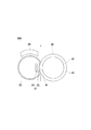
図4には、定着ニップN位置にあって矢印Tで示す、記録材Pの搬送方向と直交する幅方向、つまり定着ローラ30および加圧ローラ40のスラスト方向における端部を拡大して示す。
4 is an enlarged view of the width direction perpendicular to the conveying direction of the recording material P, that is, the end of the fixing
図示するとおり、記録材Pの搬送方向と直交する幅方向Tにおける、加圧ローラ40で定着ニップNを形成する部分の長さL1を、弾性断熱層35および誘導発熱層36の長さL2より長く形成する。そして、定着回転体33を介して支持部材32に加圧ローラ40を押し当てると、支持部材32の弾性断熱層35に弾性反発力を生ずるが、その弾性反発力を、定着回転体33の誘導発熱層36の幅方向Tの長さの全長にわたり加圧ローラ40で受け止める。この例では、加圧ローラ40側の長さL1を定着回転体33側の長さL2よりも長く形成したが、L1とL2とを等しく形成してもよい。
As shown in the drawing, the length L1 of the portion where the fixing nip N is formed by the
そして、図2において、定着ローラ30の回転とともに加圧ローラ40を従動回転するとともに、誘導コイル50に電流を流すことにより高周波の磁場が誘起し、定着回転体33に設ける誘導発熱層36の誘導コイル50側に誘導電流を発生して、定着ローラ30の表層をジュール熱により発熱して加熱し、ウォームアップ終了後に画像形成をスタートして定着ニップNに記録材Pを通す。
In FIG. 2, the
このようにすることにより、弾性断熱層35を有する支持部材32の外側に、誘導発熱層36を有する定着回転体33を設け、その定着回転体33を介して支持部材32に加圧ローラ40を押し当てて定着ニップNを形成し、その定着ニップNに記録材Pを通してその記録材P上に画像を定着する定着装置300において、金属を含むことで渦電流負荷最適値における誘導発熱層36を薄くして定着回転体33の一層の低熱容量化を実現しながら、十分な定着ニップNを形成するとともに、定着回転体33の誘導発熱層36にせん断力が働くことなく、定着回転体33の幅方向Tの両端縁の破損を防止することができる。
In this way, the fixing
図5には、画像形成装置本体100に備える定着装置300の他例の構成を示す。
この図5に示す例では、支持部材32と定着回転体33とを別体でつくり、ローラ状の支持部材32とスリーブ状のローラ60とに、可撓性部材である無端ベルト状の定着回転体33を掛けまわし、内側からテンションローラ61を押し当てて張り渡してなる。
FIG. 5 shows a configuration of another example of the fixing
In the example shown in FIG. 5, the
ローラ状の支持部材32は、同様に、芯金34のまわりに弾性断熱層35を設けてなる。一方、無端ベルト状の定着回転体33は、図3(C)に示すように、基材62を設け、その基材62上に順に誘導発熱層36、弾性体層37、離型層38を形成してなる。基材62は、ヤング率の高い厚さ100μm以下の非磁性ステンレスを用いてつくり、過度にならない範囲で定着回転体33の曲げ剛性を高めて、定着ニップNにおいて定着回転体33が受ける繰返し応力に対する耐久性を適度に向上する。
Similarly, the roller-
基材62は、この他にも、例えば厚さ300μm以下のポリイミドを用いて形成することもできる。厚さ300μm以下とするので、誘導発熱層36の曲げ剛性を過大にならない範囲で高め、定着ニップNにおいて定着回転体33が受ける繰返し応力に対する耐久性を適度に向上することができる。
In addition to this, the
そして、定着回転体33を介して支持部材32に加圧部材である加圧ローラ40を押し当てて、記録材Pを矢示方向に通す定着ニップNを形成する一方、定着回転体33を介してスリーブ状のローラ60のまわり半周を誘導コイル50で被ってなる。誘導コイル50には、同様に、インバータ回路52を接続し、インバータ回路52には制御回路53を接続する。制御回路53には、サーミスタ54からの信号を入力する。
Then, a
加圧ローラ40は、同様に、芯金42の外周にゴム層43を設けて構成する。この例では、ヒータ63を内蔵する。このヒータ63を設けると、定着立ち上げ時間を速くすることができるが、その分、消費電力が大きくなるので、省エネルギを重視する場合にはなくてもよい。
Similarly, the
図6には、図5の定着ニップN位置にあって矢印Tで示す、記録材Pの搬送方向と直交する幅方向、つまり定着ローラ30および加圧ローラ40のスラスト方向における端部を拡大して示す。
6 is an enlarged view of the width direction perpendicular to the conveying direction of the recording material P, that is, the end of the fixing
図示するとおり、記録材Pの搬送方向と直交する幅方向Tにおける、加圧ローラ40での、定着ニップNを形成する部分の長さL1を、弾性断熱層35および誘導発熱層36の長さL2より長く形成する。そして、定着回転体33を介して支持部材32に加圧ローラ40を押し当てると、支持部材32の弾性断熱層35に弾性反発力を生ずるが、その弾性反発力を、定着回転体33の誘導発熱層36の幅方向Tの長さの全長にわたり加圧ローラ40で受け止めるようにする。この例でも、加圧ローラ40側の長さL1を定着回転体33側の長さL2よりも長く形成したが、L1とL2とを等しく形成してもよい。
As shown in the drawing, the length L1 of the portion forming the fixing nip N in the
そして、図5において、支持部材32の回転とともにローラ60およびテンションローラ61を従動回転しながら定着回転体33を回転し、加圧ローラ40を従動回転する。同時に、誘導コイル50に電流を流すことにより高周波の磁場が誘起し、定着回転体33に設ける誘導発熱層36の誘導コイル50側に誘導電流を発生して、定着回転体33の表層をジュール熱により発熱して加熱し、ウォームアップ終了後に画像形成をスタートして定着ニップNに記録材Pを通す。
In FIG. 5, the fixing
このようにすることにより、弾性断熱層35を有する支持部材32の外側に、誘導発熱層36を有する定着回転体33を設け、その定着回転体33を介して支持部材32に加圧ローラ40を押し当てて定着ニップNを形成し、その定着ニップNに記録材Pを通してその記録材P上に画像を定着する定着装置300において、金属を含んで渦電流負荷最適値における誘導発熱層36を薄くして定着回転体33の一層の低熱容量化を実現しながら、十分な定着ニップNを形成するとともに、無端ベルト状の定着回転体33の誘導発熱層36にせん断力が働くことなく、定着回転体33の幅方向Tの両端縁の破損を防止することができる。
In this way, the fixing
なお、図示例では、複数のローラ状の部材32、60、61に定着回転体33を掛けまわしたが、ローラ状の部材に限らず、パッドに掛けまわすようにしてもよい。また、支持部材32を駆動して定着回転体33を回転したが、定着回転体33を掛けまわす他のローラ状の部材を駆動して定着回転体33を回転するようにしてもよいし、加圧ローラ40を駆動することにより定着回転体33を回転するようにしてもよい。さらに、加圧部材である加圧ローラ40は、ローラに限らず、パッドであってもよい。
In the illustrated example, the fixing
図7には、画像形成装置本体に備える定着装置300のさらに他例の構成を示す。
この例の定着装置300でも、支持部材32と定着回転体33とを別体でつくり、支持部材32をパッドで形成して、その支持部材32に無端状の可撓性部材であるスリーブ状の定着回転体33を掛けてなる。
FIG. 7 shows a configuration of still another example of the fixing
Also in the
パッドで形成した支持部材32は、基材64の上に弾性断熱層35を設けてなる。一方、スリーブ状の定着回転体33は、図5の定着回転体33と同様に図3(C)に示すように、基材62を設け、その基材62上に誘導発熱層36、弾性体層37、離型層38を形成してなる。基材62は、ヤング率の高い厚さ100μm以下の非磁性ステンレスや厚さ300μm以下のポリイミドを用いてつくる。支持部材32と定着回転体33との間には、好ましくは、オイルやグリースなどの低摩擦部材を介在するとよい。
The
そして、定着回転体33を介して支持部材32に、加圧部材である加圧ローラ40を押し当てて、記録材Pを矢示方向に通す定着ニップNを形成する。加圧ローラ40は、同様に、芯金42の外周にゴム層43を設けて構成する。一方、定着回転体33のまわりを誘導コイル50で被ってなる。図示省略するが、誘導コイル50には、同様に、インバータ回路を接続し、インバータ回路には制御回路を接続する。制御回路には、サーミスタからの信号を入力する。
Then, a
さらに、この例でも、記録材Pの搬送方向と直交する幅方向Tの長さが、弾性断熱層35および誘導発熱層36よりも、加圧ローラ40の定着ニップNを形成する部分の方を長くする。そして、定着回転体33を介して支持部材32に加圧ローラ40を押し当てると、支持部材32の弾性断熱層35に弾性反発力を生ずるが、その弾性反発力を、定着回転体33の誘導発熱層36の幅方向長さの全長にわたって加圧ローラ40で受け止めるようにする。
Further, in this example as well, the length of the width direction T perpendicular to the conveying direction of the recording material P is longer in the portion where the fixing nip N of the
そして、加圧ローラ40の回転とともに定着回転体33を回転する一方、誘導コイル50に電流を流すことにより高周波の磁場が誘起し、定着回転体33に設ける誘導発熱層36の誘導コイル50側に誘導電流を発生して、定着回転体33の表層をジュール熱により発熱して定着回転体33を加熱し、ウォームアップ終了後に画像形成をスタートして定着ニップNに記録材Pを通す。
The fixing
このようにすることにより、弾性断熱層35を有する支持部材32の外側に、誘導発熱層36を有する定着回転体33を設け、その定着回転体33を介して支持部材32に加圧ローラ40を押し当てて定着ニップNを形成し、その定着ニップNに記録材Pを通してその記録材P上に画像を定着する定着装置300において、金属を含んで渦電流負荷最適値における誘導発熱層36を薄くして定着回転体33の一層の低熱容量化を実現しながら、十分な定着ニップNを形成するとともに、スリーブ状の定着回転体33の誘導発熱層36にせん断力が働くことなく、定着回転体33の幅方向Tの両端縁の機械強度を確保して破損を防止することができる。
In this way, the fixing
なお、上述した例では、加圧部材である加圧ローラ40を回転することにより、パッドで形成した支持部材32に掛ける定着回転体33を回転したが、支持部材32をローラでつくり、その回転により定着回転体33を回転するようにしてもよい。このときは、加圧部材32は、ローラで形成しもパッドで形成してもよい。
In the above-described example, the rotation of the
ところで、定着回転体33として無端ベルト状やスリーブ状のものを用いる場合のように、定着回転体33を支持部材32と別体に形成して定着回転体33を支持部材32に掛けたときには、定着回転体33の回転とともに片寄りを生じ、それを掛ける支持部材32上を、記録材Pの搬送方向と直交する幅方向Tに移動することがある。
By the way, when the fixing
図8には、定着回転体33が片寄りを生じて側板65に当たった状態を示す。図9には、定着回転体33が側板65に当たり、定着回転体33の幅方向Tの端縁66を破損した状態を示す。
図9に示すように、定着回転体33が片寄りを生じて側板65に強く当たると、定着回転体33の幅方向Tの端縁66が破損することがある。
FIG. 8 shows a state in which the fixing
As shown in FIG. 9, when the fixing
図10には、定着回転体33の幅方向端縁66の破損を防止すべく、定着回転体33の両端縁に寄り止め部材68を備えた例を示す。
上述したごとく、支持部材32をローラまたはパッドで形成し、定着回転体33を無端状の可撓性部材で形成して支持部材32に掛ける場合には、図示するとおり、支持部材32の幅方向Tの長さを定着回転体33の幅方向Tの長さより短くして、その短くしてできた定着回転体33の幅方向Tの両端縁内面に、耐熱樹脂製などの寄り止め部材68を取り付ける。
FIG. 10 shows an example in which a
As described above, when the
そして、定着回転体33が回転とともに片寄りを生じて支持部材32上を幅方向に移動したとき、寄り止め部材68を支持部材32の幅方向Tの両端面70に当てて定着回転体33のそれ以上の片寄りを阻止し、側板65に当たることを防いで定着回転体33の両端縁が破損することを防止する。
When the fixing
30 定着ローラ
32 支持部材
33 定着回転体
35 弾性断熱層(弾性層)
36 誘導発熱層(発熱層)
37 弾性体層
38 離型層
40 加圧ローラ(加圧部材)
50 誘導コイル
62 基材
68 寄り止め部材
300 定着装置
L1 加圧部材の、定着ニップを形成する部分の長さ
L2 弾性断熱層および誘導発熱層の長さ
N 定着ニップ
P 記録材
T 記録材の搬送方向と直交する幅方向
30
36 Induction heating layer (heating layer)
37
50
Claims (21)
前記記録材の搬送方向と直交する幅方向における、前記加圧部材で前記定着ニップを形成する部分の長さを、前記発熱層の長さ以上に形成することを特徴とする定着装置。 A fixing rotator having a heat generating layer is provided outside a support member having an elastic layer, and a pressure member is pressed against the support member through the fixing rotator to form a fixing nip, and a recording material is formed in the fixing nip. Through the fixing device for fixing the image on the recording material through
A fixing device in which a length of a portion where the fixing nip is formed by the pressure member in a width direction orthogonal to a conveyance direction of the recording material is formed to be longer than a length of the heat generating layer.
Priority Applications (3)
| Application Number | Priority Date | Filing Date | Title |
|---|---|---|---|
| JP2006283310A JP2007279669A (en) | 2006-03-13 | 2006-10-18 | Fixing device, image forming apparatus, and fixing nip forming method of fixing device |
| EP07103653A EP1835362B1 (en) | 2006-03-13 | 2007-03-07 | Fixer and image forming apparatus including the same |
| US11/685,504 US7817952B2 (en) | 2006-03-13 | 2007-03-13 | Fixer and image forming apparatus including the same |
Applications Claiming Priority (2)
| Application Number | Priority Date | Filing Date | Title |
|---|---|---|---|
| JP2006067386 | 2006-03-13 | ||
| JP2006283310A JP2007279669A (en) | 2006-03-13 | 2006-10-18 | Fixing device, image forming apparatus, and fixing nip forming method of fixing device |
Publications (1)
| Publication Number | Publication Date |
|---|---|
| JP2007279669A true JP2007279669A (en) | 2007-10-25 |
Family
ID=38016484
Family Applications (1)
| Application Number | Title | Priority Date | Filing Date |
|---|---|---|---|
| JP2006283310A Pending JP2007279669A (en) | 2006-03-13 | 2006-10-18 | Fixing device, image forming apparatus, and fixing nip forming method of fixing device |
Country Status (3)
| Country | Link |
|---|---|
| US (1) | US7817952B2 (en) |
| EP (1) | EP1835362B1 (en) |
| JP (1) | JP2007279669A (en) |
Cited By (3)
| Publication number | Priority date | Publication date | Assignee | Title |
|---|---|---|---|---|
| JP2009223315A (en) * | 2008-03-17 | 2009-10-01 | Toshiba Corp | Fixing device and developer fixing method of fixing device |
| JP2011022575A (en) * | 2009-07-20 | 2011-02-03 | Xerox Corp | Induction heating carbon nanotube fixer |
| JP2012093412A (en) * | 2010-10-25 | 2012-05-17 | Kyocera Mita Corp | Fixing device and image forming apparatus |
Families Citing this family (61)
| Publication number | Priority date | Publication date | Assignee | Title |
|---|---|---|---|---|
| JP5065871B2 (en) * | 2007-12-11 | 2012-11-07 | 株式会社リコー | Fixing apparatus and image forming apparatus |
| JP5286869B2 (en) * | 2008-03-25 | 2013-09-11 | 株式会社リコー | Fixing device, image forming apparatus |
| JP5360686B2 (en) * | 2009-05-27 | 2013-12-04 | 株式会社リコー | Fixing apparatus and image forming apparatus |
| JP5418068B2 (en) * | 2009-08-26 | 2014-02-19 | 株式会社リコー | Fixing apparatus and image forming apparatus |
| JP5375469B2 (en) * | 2009-09-14 | 2013-12-25 | 株式会社リコー | Fixing apparatus and image forming apparatus |
| JP2011081338A (en) * | 2009-09-14 | 2011-04-21 | Ricoh Co Ltd | Fixing device |
| JP5581634B2 (en) * | 2009-09-15 | 2014-09-03 | 株式会社リコー | Fixing apparatus and image forming apparatus |
| JP5333194B2 (en) * | 2009-12-22 | 2013-11-06 | 株式会社リコー | Fixing apparatus and image forming apparatus |
| US8488981B2 (en) * | 2010-03-11 | 2013-07-16 | Ricoh Company, Ltd. | Fixing device and image forming apparatus using the same |
| JP5560791B2 (en) * | 2010-03-16 | 2014-07-30 | 株式会社リコー | Thermal fixing device and image forming apparatus |
| JP2011191607A (en) | 2010-03-16 | 2011-09-29 | Ricoh Co Ltd | Fixing device and image forming apparatus |
| JP5515898B2 (en) * | 2010-03-17 | 2014-06-11 | 株式会社リコー | Fixing apparatus and image forming apparatus |
| JP2011197154A (en) | 2010-03-17 | 2011-10-06 | Ricoh Co Ltd | Fixing device, fixing method, image forming apparatus, and image forming method |
| JP5510727B2 (en) | 2010-06-21 | 2014-06-04 | 株式会社リコー | Fixing apparatus and image forming apparatus |
| JP5617431B2 (en) | 2010-08-19 | 2014-11-05 | 株式会社リコー | Fixing apparatus and image forming apparatus |
| JP5593973B2 (en) | 2010-08-30 | 2014-09-24 | 株式会社リコー | Fixing apparatus and image forming apparatus |
| JP5610148B2 (en) | 2010-10-18 | 2014-10-22 | 株式会社リコー | Image forming apparatus |
| JP2012088491A (en) | 2010-10-19 | 2012-05-10 | Ricoh Co Ltd | Fixing roller, fixing device, and image forming apparatus |
| JP5707867B2 (en) | 2010-11-01 | 2015-04-30 | 株式会社リコー | Fixing apparatus and image forming apparatus |
| JP2012118481A (en) | 2010-11-10 | 2012-06-21 | Ricoh Co Ltd | Fixing device, image forming apparatus, and method for controlling fixing device |
| JP5625924B2 (en) | 2011-01-11 | 2014-11-19 | 株式会社リコー | Electromagnetic induction heating type fixing device and image forming apparatus |
| JP2012168403A (en) | 2011-02-15 | 2012-09-06 | Ricoh Co Ltd | Fixing device and image forming apparatus |
| JP5796303B2 (en) | 2011-02-16 | 2015-10-21 | 株式会社リコー | Fixing apparatus and image forming apparatus |
| JP5760505B2 (en) | 2011-02-25 | 2015-08-12 | 株式会社リコー | Fixing apparatus and image forming apparatus |
| US8855542B2 (en) * | 2011-08-26 | 2014-10-07 | Kabushiki Kaisha Toshiba | Fuser, image forming apparatus, and image forming method |
| JP5737629B2 (en) | 2011-12-26 | 2015-06-17 | 株式会社リコー | Fixing apparatus and image forming apparatus |
| JP6136221B2 (en) | 2011-12-27 | 2017-05-31 | 株式会社リコー | Fixing apparatus and image forming apparatus |
| JP6136220B2 (en) | 2011-12-27 | 2017-05-31 | 株式会社リコー | Fixing apparatus and image forming apparatus |
| JP5796711B2 (en) | 2011-12-28 | 2015-10-21 | 株式会社リコー | Fixing apparatus and image forming apparatus |
| JP5904325B2 (en) | 2011-12-28 | 2016-04-13 | 株式会社リコー | Fixing apparatus and image forming apparatus |
| CN103186087B (en) | 2011-12-28 | 2016-08-03 | 株式会社理光 | Fixing device, imaging device and separating member |
| JP5928783B2 (en) | 2012-01-11 | 2016-06-01 | 株式会社リコー | Fixing apparatus and image forming apparatus |
| JP5761524B2 (en) | 2012-01-13 | 2015-08-12 | 株式会社リコー | Fixing apparatus and image forming apparatus |
| JP5737520B2 (en) | 2012-01-13 | 2015-06-17 | 株式会社リコー | Fixing apparatus and image forming apparatus |
| JP5970828B2 (en) | 2012-01-19 | 2016-08-17 | 株式会社リコー | Separating member, fixing device, and image forming apparatus |
| JP6024108B2 (en) | 2012-01-19 | 2016-11-09 | 株式会社リコー | Fixing apparatus and image forming apparatus |
| JP6333511B6 (en) | 2012-01-23 | 2023-11-08 | 株式会社リコー | Fixing device and image forming device |
| JP5967468B2 (en) | 2012-01-24 | 2016-08-10 | 株式会社リコー | Fixing apparatus and image forming apparatus |
| JP5943231B2 (en) | 2012-01-26 | 2016-07-05 | 株式会社リコー | Fixing apparatus and image forming apparatus |
| JP6035668B2 (en) | 2012-01-27 | 2016-11-30 | 株式会社リコー | Fixing apparatus and image forming apparatus |
| JP6052598B2 (en) | 2012-01-30 | 2016-12-27 | 株式会社リコー | Fixing apparatus and image forming apparatus |
| JP6051741B2 (en) | 2012-01-31 | 2016-12-27 | 株式会社リコー | Fixing apparatus and image forming apparatus |
| JP5963105B2 (en) | 2012-02-02 | 2016-08-03 | 株式会社リコー | Fixing apparatus and image forming apparatus |
| JP6135051B2 (en) | 2012-02-09 | 2017-05-31 | 株式会社リコー | Fixing apparatus and image forming apparatus |
| JP5896281B2 (en) | 2012-02-09 | 2016-03-30 | 株式会社リコー | Image forming apparatus |
| JP6423994B2 (en) | 2012-02-09 | 2018-11-14 | 株式会社リコー | Fixing apparatus and image forming apparatus |
| JP6032525B2 (en) | 2012-02-09 | 2016-11-30 | 株式会社リコー | Image forming apparatus |
| JP5948923B2 (en) | 2012-02-09 | 2016-07-06 | 株式会社リコー | Fixing apparatus and image forming apparatus |
| JP6103679B2 (en) | 2012-02-09 | 2017-03-29 | 株式会社リコー | Fixing apparatus and image forming apparatus |
| JP6003619B2 (en) | 2012-02-09 | 2016-10-05 | 株式会社リコー | Fixing apparatus and image forming apparatus |
| JP6201312B2 (en) | 2012-02-09 | 2017-09-27 | 株式会社リコー | Image forming apparatus |
| JP6019785B2 (en) | 2012-02-09 | 2016-11-02 | 株式会社リコー | Fixing apparatus and image forming apparatus |
| JP6209311B2 (en) | 2012-02-09 | 2017-10-04 | 株式会社リコー | Fixing apparatus and image forming apparatus |
| JP2013164463A (en) | 2012-02-09 | 2013-08-22 | Ricoh Co Ltd | Fixation device and image formation apparatus |
| JP5995132B2 (en) | 2012-02-09 | 2016-09-21 | 株式会社リコー | Fixing apparatus and image forming apparatus |
| US9026024B2 (en) | 2012-02-09 | 2015-05-05 | Ricoh Company, Ltd. | Fixing device capable of minimizing damage of endless rotary body and image forming apparatus incorporating same |
| JP5850326B2 (en) | 2012-02-09 | 2016-02-03 | 株式会社リコー | Fixing apparatus and image forming apparatus |
| JP6019779B2 (en) | 2012-02-09 | 2016-11-02 | 株式会社リコー | Fixing apparatus and image forming apparatus |
| JP2013195857A (en) | 2012-03-22 | 2013-09-30 | Ricoh Co Ltd | Fixing device, and image forming apparatus |
| JP5950152B2 (en) | 2012-03-22 | 2016-07-13 | 株式会社リコー | Fixing apparatus and image forming apparatus |
| JP6016071B2 (en) | 2012-05-18 | 2016-10-26 | 株式会社リコー | Fixing apparatus and image forming apparatus |
Citations (5)
| Publication number | Priority date | Publication date | Assignee | Title |
|---|---|---|---|---|
| JP2002093566A (en) * | 2000-09-12 | 2002-03-29 | Sharp Corp | Heating equipment |
| JP2004205814A (en) * | 2002-12-25 | 2004-07-22 | Nitto Kogyo Co Ltd | Fixing roller and fixing device equipped with the fixing roller |
| JP2005203273A (en) * | 2004-01-16 | 2005-07-28 | Fuji Xerox Co Ltd | Heater, fixing device, and image recording device using it |
| JP2005202272A (en) * | 2004-01-19 | 2005-07-28 | Konica Minolta Business Technologies Inc | Induction heating fixing device |
| JP2007108212A (en) * | 2005-10-11 | 2007-04-26 | Konica Minolta Business Technologies Inc | Fixing device |
Family Cites Families (18)
| Publication number | Priority date | Publication date | Assignee | Title |
|---|---|---|---|---|
| US4942434A (en) * | 1987-12-11 | 1990-07-17 | Ricoh Company, Ltd. | Fixed roller for an electrostatic image recorder |
| JPH03233586A (en) * | 1990-02-09 | 1991-10-17 | Canon Inc | Fixing device |
| JPH0816007A (en) | 1994-06-28 | 1996-01-19 | Canon Inc | Heating apparatus and image forming apparatus |
| JP3350315B2 (en) | 1995-09-09 | 2002-11-25 | 株式会社リコー | Fixing device |
| JPH09218601A (en) | 1996-02-14 | 1997-08-19 | Minolta Co Ltd | Belt fixing device |
| JP2002006649A (en) * | 2000-06-19 | 2002-01-11 | Sharp Corp | Image forming device |
| JP2003017221A (en) | 2001-07-03 | 2003-01-17 | Ricoh Co Ltd | Heating apparatus and image forming device |
| JP2004205838A (en) | 2002-12-25 | 2004-07-22 | Matsushita Electric Ind Co Ltd | Image heating device and image forming apparatus |
| CN100492213C (en) * | 2003-01-30 | 2009-05-27 | 夏普株式会社 | Heater, imaging device having same and heating method |
| JP2005037858A (en) | 2003-06-25 | 2005-02-10 | Matsushita Electric Ind Co Ltd | Electromagnetic induction heat type fixing device and image forming apparatus provided with the same |
| JP2005043476A (en) | 2003-07-23 | 2005-02-17 | Toshiba Corp | Fixing device for image forming apparatus and image forming apparatus |
| JP2005189404A (en) | 2003-12-25 | 2005-07-14 | Ricoh Co Ltd | Fixing belt and fixing device using the same |
| JP2005208474A (en) | 2004-01-26 | 2005-08-04 | Konica Minolta Business Technologies Inc | Fixing device |
| JP4298542B2 (en) * | 2004-02-20 | 2009-07-22 | キヤノン株式会社 | Image heating device |
| JP4722494B2 (en) * | 2004-02-25 | 2011-07-13 | 株式会社沖データ | Fixing device |
| JP2005241891A (en) | 2004-02-26 | 2005-09-08 | Ricoh Co Ltd | Fixing device and image forming apparatus |
| JP2005250298A (en) | 2004-03-05 | 2005-09-15 | Ricoh Co Ltd | Fixing device and image forming apparatus |
| JP2005345989A (en) | 2004-06-07 | 2005-12-15 | Sharp Corp | Heating device and image forming apparatus |
-
2006
- 2006-10-18 JP JP2006283310A patent/JP2007279669A/en active Pending
-
2007
- 2007-03-07 EP EP07103653A patent/EP1835362B1/en not_active Expired - Fee Related
- 2007-03-13 US US11/685,504 patent/US7817952B2/en active Active
Patent Citations (5)
| Publication number | Priority date | Publication date | Assignee | Title |
|---|---|---|---|---|
| JP2002093566A (en) * | 2000-09-12 | 2002-03-29 | Sharp Corp | Heating equipment |
| JP2004205814A (en) * | 2002-12-25 | 2004-07-22 | Nitto Kogyo Co Ltd | Fixing roller and fixing device equipped with the fixing roller |
| JP2005203273A (en) * | 2004-01-16 | 2005-07-28 | Fuji Xerox Co Ltd | Heater, fixing device, and image recording device using it |
| JP2005202272A (en) * | 2004-01-19 | 2005-07-28 | Konica Minolta Business Technologies Inc | Induction heating fixing device |
| JP2007108212A (en) * | 2005-10-11 | 2007-04-26 | Konica Minolta Business Technologies Inc | Fixing device |
Cited By (3)
| Publication number | Priority date | Publication date | Assignee | Title |
|---|---|---|---|---|
| JP2009223315A (en) * | 2008-03-17 | 2009-10-01 | Toshiba Corp | Fixing device and developer fixing method of fixing device |
| JP2011022575A (en) * | 2009-07-20 | 2011-02-03 | Xerox Corp | Induction heating carbon nanotube fixer |
| JP2012093412A (en) * | 2010-10-25 | 2012-05-17 | Kyocera Mita Corp | Fixing device and image forming apparatus |
Also Published As
| Publication number | Publication date |
|---|---|
| US7817952B2 (en) | 2010-10-19 |
| EP1835362A1 (en) | 2007-09-19 |
| EP1835362B1 (en) | 2011-05-11 |
| US20070212089A1 (en) | 2007-09-13 |
Similar Documents
| Publication | Publication Date | Title |
|---|---|---|
| JP2007279669A (en) | Fixing device, image forming apparatus, and fixing nip forming method of fixing device | |
| JP5625924B2 (en) | Electromagnetic induction heating type fixing device and image forming apparatus | |
| JP4949803B2 (en) | Fixing apparatus and image forming apparatus | |
| JP3998955B2 (en) | Fixing device and image forming apparatus using the same | |
| JP2005326524A (en) | Fixing device and image forming apparatus | |
| JP2007322975A (en) | Fixing device and image forming apparatus | |
| JP6111657B2 (en) | Fixing apparatus and image forming apparatus | |
| JP6350137B2 (en) | Fixing apparatus and image forming apparatus | |
| JP2011186468A (en) | Fixing apparatus | |
| JP2002056960A (en) | Heating device and image forming device | |
| JP4766107B2 (en) | Fixing apparatus and image forming apparatus having the same | |
| JP4376620B2 (en) | Image forming apparatus | |
| JP5392475B2 (en) | Fixing apparatus and image forming apparatus | |
| JP2004264398A (en) | Fixing device and image forming apparatus using same | |
| JP2005181464A (en) | Fixing device and image forming apparatus | |
| JP5016128B2 (en) | Fixing apparatus and image forming apparatus | |
| JP2007292949A (en) | Image heating device | |
| JP2005338501A (en) | Heating device | |
| JP2011118413A (en) | Fixing device and image forming apparatus | |
| JP6127603B2 (en) | Fixing apparatus and image forming apparatus | |
| JP4115137B2 (en) | Fixing device | |
| JP2011118164A (en) | Fixing device, and image forming apparatus | |
| JP5550244B2 (en) | Fixing apparatus and image forming apparatus | |
| JP4934350B2 (en) | Fixing device, image forming apparatus | |
| JP2006098931A (en) | Endless belt, heater and image forming apparatus |
Legal Events
| Date | Code | Title | Description |
|---|---|---|---|
| A621 | Written request for application examination |
Free format text: JAPANESE INTERMEDIATE CODE: A621 Effective date: 20090710 |
|
| A131 | Notification of reasons for refusal |
Free format text: JAPANESE INTERMEDIATE CODE: A131 Effective date: 20110524 |
|
| A521 | Written amendment |
Free format text: JAPANESE INTERMEDIATE CODE: A523 Effective date: 20110719 |
|
| A131 | Notification of reasons for refusal |
Free format text: JAPANESE INTERMEDIATE CODE: A131 Effective date: 20110811 |
|
| A02 | Decision of refusal |
Free format text: JAPANESE INTERMEDIATE CODE: A02 Effective date: 20111206 |