JP2007278564A - Fuel tank and fuel supply system - Google Patents
Fuel tank and fuel supply system Download PDFInfo
- Publication number
- JP2007278564A JP2007278564A JP2006103519A JP2006103519A JP2007278564A JP 2007278564 A JP2007278564 A JP 2007278564A JP 2006103519 A JP2006103519 A JP 2006103519A JP 2006103519 A JP2006103519 A JP 2006103519A JP 2007278564 A JP2007278564 A JP 2007278564A
- Authority
- JP
- Japan
- Prior art keywords
- fuel
- combustion inhibitor
- flow path
- combustion
- tank
- Prior art date
- Legal status (The legal status is an assumption and is not a legal conclusion. Google has not performed a legal analysis and makes no representation as to the accuracy of the status listed.)
- Pending
Links
Images
Classifications
-
- Y—GENERAL TAGGING OF NEW TECHNOLOGICAL DEVELOPMENTS; GENERAL TAGGING OF CROSS-SECTIONAL TECHNOLOGIES SPANNING OVER SEVERAL SECTIONS OF THE IPC; TECHNICAL SUBJECTS COVERED BY FORMER USPC CROSS-REFERENCE ART COLLECTIONS [XRACs] AND DIGESTS
- Y02—TECHNOLOGIES OR APPLICATIONS FOR MITIGATION OR ADAPTATION AGAINST CLIMATE CHANGE
- Y02E—REDUCTION OF GREENHOUSE GAS [GHG] EMISSIONS, RELATED TO ENERGY GENERATION, TRANSMISSION OR DISTRIBUTION
- Y02E60/00—Enabling technologies; Technologies with a potential or indirect contribution to GHG emissions mitigation
- Y02E60/30—Hydrogen technology
- Y02E60/32—Hydrogen storage
-
- Y—GENERAL TAGGING OF NEW TECHNOLOGICAL DEVELOPMENTS; GENERAL TAGGING OF CROSS-SECTIONAL TECHNOLOGIES SPANNING OVER SEVERAL SECTIONS OF THE IPC; TECHNICAL SUBJECTS COVERED BY FORMER USPC CROSS-REFERENCE ART COLLECTIONS [XRACs] AND DIGESTS
- Y02—TECHNOLOGIES OR APPLICATIONS FOR MITIGATION OR ADAPTATION AGAINST CLIMATE CHANGE
- Y02E—REDUCTION OF GREENHOUSE GAS [GHG] EMISSIONS, RELATED TO ENERGY GENERATION, TRANSMISSION OR DISTRIBUTION
- Y02E60/00—Enabling technologies; Technologies with a potential or indirect contribution to GHG emissions mitigation
- Y02E60/30—Hydrogen technology
- Y02E60/50—Fuel cells
Landscapes
- Filling Or Discharging Of Gas Storage Vessels (AREA)
- Feeding And Controlling Fuel (AREA)
- Fuel Cell (AREA)
Abstract
【課題】簡易な構成で高い信頼性を維持できる燃料タンクおよび燃料供給システムを提供する。
【解決手段】燃料と当該燃料による燃焼を抑制する燃焼抑制剤とを含むことを特徴とする燃料タンクである。また、燃料と当該燃料による燃焼を抑制する燃焼抑制剤とを含む燃料タンクと、前記燃料および前記燃焼抑制剤が流通する流路が、流通方向に分岐し、その後連結するバイパス構造を有し、前記バイパス構造中の1の流路に燃焼抑制剤除去手段が設けられており、他の流路に流量制御弁が設けられていることを特徴とする燃料供給システムである。
【選択図】図1A fuel tank and a fuel supply system capable of maintaining high reliability with a simple configuration are provided.
A fuel tank includes a fuel and a combustion inhibitor that suppresses combustion by the fuel. A fuel tank including a fuel and a combustion inhibitor that suppresses combustion by the fuel; and a flow path through which the fuel and the combustion inhibitor circulate branch in a flow direction and has a bypass structure that is connected thereafter. The fuel supply system is characterized in that a combustion inhibitor removing means is provided in one flow path in the bypass structure, and a flow rate control valve is provided in another flow path.
[Selection] Figure 1
Description
本発明は、水素などを燃料とする燃料タンクおよび燃料供給システムに関する。 The present invention relates to a fuel tank and a fuel supply system using hydrogen or the like as fuel.
自動車が高速で衝撃を受けると、車体が破損するほかに、燃料タンクや燃料供給パイプが破壊されて、火災の原因となる可能性がある。これは、燃料タンクなどから漏れた燃料に引火するために起こると考えられる。 When an automobile is impacted at a high speed, in addition to damaging the vehicle body, the fuel tank and fuel supply pipe may be destroyed, causing a fire. This is considered to occur because the fuel leaked from the fuel tank or the like is ignited.
このような事故を未然に防ぐために、燃料タンクや燃料供給パイプなどを頑丈な構造とすることが考えられるが、その強度にも限界がある。また、燃料タンクなどの重量が大きくなってしまう問題もある。 In order to prevent such an accident, it is conceivable that the fuel tank, the fuel supply pipe, and the like have a sturdy structure, but their strength is limited. There is also a problem that the weight of the fuel tank and the like becomes large.
そこで、特許文献1には、消化剤を噴射する機構を有する自動車の安全消防装置が提案されている。しかし、当該装置は複雑であり、そのため故障などのおそれがないような設計が必要となり設計も複雑になる。
本発明は、上記従来の問題を解決することを目的とする。すなわち、本発明は、簡易な構成で高い信頼性を維持できる燃料タンクおよび燃料供給システムを提供することを目的とする。 An object of the present invention is to solve the above-described conventional problems. That is, an object of the present invention is to provide a fuel tank and a fuel supply system that can maintain high reliability with a simple configuration.
上記課題を解決すべく鋭意検討した結果、本発明者は、下記本発明に想到し当該課題を解決できることを見出した。すなわち、本発明は、燃料と当該燃料による燃焼を抑制する燃焼抑制剤とを含むことを特徴とする燃料タンクである。 As a result of intensive studies to solve the above problems, the present inventor has conceived the following present invention and found that the problems can be solved. That is, this invention is a fuel tank characterized by including a fuel and the combustion inhibitor which suppresses combustion by the said fuel.
本発明の燃料タンクは、燃料と燃焼抑制剤とを含むだけの構成なので、燃料タンク全体の構造を簡易なものとすることができる。そして、複雑な構成とした場合に生じ得る種々のトラブルがないため、高い信頼性を維持することができる。 Since the fuel tank of the present invention only includes fuel and a combustion inhibitor, the structure of the entire fuel tank can be simplified. And since there is no various trouble which may arise when it is set as a complicated structure, high reliability can be maintained.
本発明においては、前記燃料が水素であり、前記燃焼抑制剤がヨウ化カリウム水溶液であることが好ましい。水素は、燃料電池の燃料ガスとしての利用価値が高い。この水素を燃料として使用する場合には、取り扱い性や燃焼抑制効果の点で、ヨウ化カリウム水溶液が燃焼抑制剤として好適である。 In the present invention, it is preferable that the fuel is hydrogen and the combustion inhibitor is an aqueous potassium iodide solution. Hydrogen has a high utility value as a fuel gas for fuel cells. When this hydrogen is used as a fuel, a potassium iodide aqueous solution is suitable as a combustion inhibitor from the viewpoint of handleability and combustion suppression effect.
また本発明においては、タンク口金部またはタンク外部で前記タンク口金部の直近部に前記燃焼抑制剤除去手段が設けられていることが好ましい。タンク口金部またはその直近部に燃焼抑制剤除去手段を設けることで、燃料供給側への燃焼抑制剤の混入を防ぐことができる。 Further, in the present invention, it is preferable that the combustion inhibitor removing means is provided in the tank base part or outside the tank in the immediate vicinity of the tank base part. By providing the combustion inhibitor removing means in the tank base portion or in the immediate vicinity thereof, mixing of the combustion inhibitor on the fuel supply side can be prevented.
さらに本発明においては、気液分離手段が設けられていることが好ましい。例えば、燃料供給先が燃料電池の燃料極の場合、水をはじめとした液体が混入することは好ましくない。すなわち、その用途に応じて気液分離手段を設けることで、燃料供給先の機器への不具合を未然に防止することができる。 Furthermore, in the present invention, it is preferable that gas-liquid separation means is provided. For example, when the fuel supply destination is a fuel electrode of a fuel cell, it is not preferable that liquid such as water is mixed. That is, by providing gas-liquid separation means according to the application, it is possible to prevent problems with the fuel supply destination device.
また本発明においては、前記燃料および前記燃焼抑制剤が流通する流路が、流通方向に分岐し、その後連結するバイパス構造を有し、前記バイパス構造中の1の流路(第1の流路)に前記燃焼抑制剤除去手段が設けられており、他の流路(第2の流路)に流量制御弁が設けられていることが好ましい。 In the present invention, the flow path through which the fuel and the combustion inhibitor flow has a bypass structure that branches in the flow direction and is connected thereafter, and one flow path (first flow path in the bypass structure) ) Is provided with the combustion inhibitor removing means, and the flow rate control valve is preferably provided in the other channel (second channel).
通常時は、バイパス構造の第2の流路に設けられた流量制御弁を閉じておき、燃料および燃焼抑制剤をバイパス構造の第1の流路に流す。第1の流路を流れる燃料および燃焼抑制剤は、途中にある燃焼抑制剤除去手段に到達し、この燃焼抑制剤除去手段により燃焼抑制剤が除去され、燃料だけがその後、流通することになる。一方、燃料漏れなどの問題が発生した場合には、流量制御弁を開き第2の流路から燃料とともに燃焼抑制剤を供給して、引火を防止する。このような簡易なバイパス構造の採用により燃焼抑制剤の供給を制御することができるため、本発明の燃料タンクを種々の燃料供給システムに組み込んでも、複雑な構成とはならず、高い信頼性を維持することができる。 In normal times, the flow control valve provided in the second flow path of the bypass structure is closed, and the fuel and the combustion inhibitor flow through the first flow path of the bypass structure. The fuel and the combustion inhibitor flowing through the first flow path reach the combustion inhibitor removing means on the way, the combustion inhibitor is removed by the combustion inhibitor removing means, and only the fuel is then circulated. . On the other hand, when a problem such as fuel leakage occurs, the flow control valve is opened and the combustion inhibitor is supplied together with the fuel from the second flow path to prevent ignition. By adopting such a simple bypass structure, it is possible to control the supply of the combustion inhibitor, so even if the fuel tank of the present invention is incorporated into various fuel supply systems, it does not become a complicated configuration and has high reliability. Can be maintained.
また、本発明は、燃料と当該燃料による燃焼を抑制する燃焼抑制剤とを含む燃料タンクと、前記燃料および前記燃焼抑制剤が流通する流路が、流通方向に分岐し、その後連結するバイパス構造を有し、前記バイパス構造中の1の流路に燃焼抑制剤除去手段が設けられており、他の流路に流量制御弁が設けられていることを特徴とする燃料供給システムである。本発明の燃料供給システムは、本発明の燃料タンクを具備し、所定のバイパス構造を有するため、簡易な構成でありながら、高い信頼性を維持することができる。 Further, the present invention provides a bypass structure in which a fuel tank including a fuel and a combustion inhibitor that suppresses combustion by the fuel, and a flow path through which the fuel and the combustion inhibitor flow are branched in the flow direction and then connected. The fuel supply system is characterized in that a combustion inhibitor removing means is provided in one flow path in the bypass structure, and a flow rate control valve is provided in the other flow path. Since the fuel supply system of the present invention includes the fuel tank of the present invention and has a predetermined bypass structure, high reliability can be maintained while having a simple configuration.
本発明の燃料タンクおよび燃料供給システムによれば、簡易な構成で高い信頼性を維持することができる。 According to the fuel tank and the fuel supply system of the present invention, high reliability can be maintained with a simple configuration.
[燃料タンク]
本発明の燃料タンクは、燃料と当該燃料による燃焼を抑制する燃焼抑制剤とを含む。燃料のほかに、上記燃焼抑制剤を含有させることで、燃料に起因する事故(引火、爆発など)を防ぐことが可能である。また、引火などが起こっても、その被害を最小限に留めることが可能である。
[Fuel tank]
The fuel tank of the present invention includes a fuel and a combustion inhibitor that suppresses combustion by the fuel. In addition to fuel, it is possible to prevent accidents (flammability, explosion, etc.) caused by fuel by containing the above-mentioned combustion inhibitor. In addition, even if ignition occurs, the damage can be kept to a minimum.
燃焼抑制剤とは、燃焼を未然に防ぐ機能のほかに引火してもその影響を最小限に抑えることができるものをいい、燃焼速度を該当ガスの音速以下とすることができるものいう。具体的には、燃料が水素の場合、ヨウ化カリウム水溶液が燃焼抑制剤となり、燃料がガソリンの場合、炭酸水素化合物類の消火剤が燃焼抑制剤となる。なお、音速の測定法としては、「URL:www.gifu−net.ed.jp/kyoka/rika/risu−tebiki/32/1onnsoku.pdf」を参考にすることが好ましい。 In addition to the function of preventing combustion in advance, the combustion inhibitor refers to an agent that can minimize the influence even when ignited, and the combustion rate can be made lower than the sound velocity of the corresponding gas. Specifically, when the fuel is hydrogen, an aqueous potassium iodide solution is a combustion inhibitor, and when the fuel is gasoline, a hydrogen carbonate-based fire extinguisher is a combustion inhibitor. As a method for measuring the speed of sound, it is preferable to refer to “URL: www.gifu-net.ed.jp/kyoka/rika/risu-tebiki/32/1onnsoku.pdf”.
タンク口金部またはタンク外部でタンク口金部の直近部には、燃焼抑制剤除去手段が設けられていることが好ましい。上記タンク口金部の直近部とは、タンク口金部の端部からタンクの下流の圧力調整弁など、燃焼抑制剤による不具合が考えられる機器までの領域をいう。除去された燃焼抑制剤は、一定量を捕集後、再び燃料タンクに戻して利用することができる。燃焼抑制剤除去手段としては、イオン交換機、活性炭フィルタなどが挙げられる。 It is preferable that a combustion inhibitor removing means is provided in the tank base part or in the immediate vicinity of the tank base part outside the tank. The nearest part of the tank base part refers to a region from the end of the tank base part to a device such as a pressure regulating valve downstream of the tank where a malfunction due to the combustion inhibitor is considered. The removed combustion inhibitor can be returned to the fuel tank for collection after a certain amount is collected. Examples of the combustion inhibitor removing means include an ion exchanger and an activated carbon filter.
また、気液分離手段が設けられていることが好ましい。気液分離手段としては、公知のサイクロン式気液分離器を使用することができる。例えば、燃料供給先が燃料電池の燃料極の場合、水をはじめとした液体が混入することは好ましくない。すなわち、その用途に応じて気液分離手段を設けることで、燃料供給先の機器への不具合を未然に防止することができる。 Moreover, it is preferable that a gas-liquid separation means is provided. A known cyclone type gas-liquid separator can be used as the gas-liquid separation means. For example, when the fuel supply destination is a fuel electrode of a fuel cell, it is not preferable that liquid such as water is mixed. That is, by providing gas-liquid separation means according to the application, it is possible to prevent problems with the fuel supply destination device.
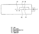
本発明の燃料タンクの好ましい態様としては、図1に示すように、燃料および燃焼抑制剤が流通する流路10が、流通方向(矢印A方向)に分岐し、その後連結するバイパス構造を有している。そして、バイパス構造中の1の流路(第1の流路12)に既述の燃焼抑制剤除去手段14が設けられており、他の流路(第2の流路16)に流量制御弁18が設けられている。
As a preferred embodiment of the fuel tank of the present invention, as shown in FIG. 1, the
通常時は、バイパス構造の第2の流路16に設けられた流量制御弁18を閉じておき、燃料および燃焼抑制剤をバイパス構造の第1の流路12に流す。第1の流路12を流れる燃料および燃焼抑制剤のうちの燃焼抑制剤は、途中にある燃焼抑制剤除去手段14により除去され、燃料だけがその後、流通することになる。一方、燃料漏れなどの問題が発生した場合には、流量制御弁18を開き第2の流路16から燃料とともに燃焼抑制剤を供給して、引火を防止する。このように、簡易なバイパス構造を採用して燃焼抑制剤の供給を制御することができるため、本発明の燃料タンクを、種々の燃料供給システムに組み込んでも、複雑な構成とはならず、高い安全性を維持することができる。
At normal times, the
[燃料供給システム]
本発明の燃料供給システムは、燃料と当該燃料による燃焼を抑制する燃焼抑制剤とを含む燃料タンクと、前記燃料および前記燃焼抑制剤が流通する流路が、流通方向に分岐し、その後連結するバイパス構造を有し、前記バイパス構造中の1の流路に燃焼抑制剤除去手段が設けられており、他の流路に流量制御弁が設けられている。
[Fuel supply system]
In the fuel supply system of the present invention, a fuel tank including a fuel and a combustion inhibitor that suppresses combustion by the fuel, and a flow path through which the fuel and the combustion inhibitor flow are branched in the flow direction and then connected. It has a bypass structure, a combustion inhibitor removing means is provided in one flow path in the bypass structure, and a flow control valve is provided in the other flow path.
例えば、本発明の燃料供給システムを燃料電池に適用する場合、流量制御弁は、センサにて水素の漏れを検知し、漏れに応じて開くような構成とすることが好ましい。具体的には、燃料タンクの内部に圧力センサを設置し、タンク内圧が急激に低下したことを検知して、水素漏れを判定することができる。流量制御弁としては、電磁駆動弁とすることが好ましい。また、流量制御弁としてバネつきチェック弁を採用することもできる。流量や圧力の急激な変化に応じて、弁を開閉することができる点で優れているといえる。さらに、流量制御弁を流量調整可能な弁とすることで、燃焼抑制剤の流量を必要に応じて制御することもできる。 For example, when the fuel supply system of the present invention is applied to a fuel cell, it is preferable that the flow control valve be configured to detect a hydrogen leak with a sensor and open in response to the leak. Specifically, a hydrogen sensor can be determined by installing a pressure sensor inside the fuel tank and detecting that the tank internal pressure has dropped sharply. The flow control valve is preferably an electromagnetically driven valve. Also, a check valve with a spring can be employed as the flow control valve. It can be said that the valve can be opened and closed in response to a rapid change in flow rate or pressure. Furthermore, the flow rate of the combustion inhibitor can be controlled as necessary by making the flow rate control valve a valve whose flow rate can be adjusted.
図1でも説明したとおり、通常時では、バイパス構造を通過した燃料ガスは、燃料電池の燃料極へと供給される。そして、燃料電池の空気極へは酸化剤ガスが供給すれば、燃料電池が作動する。 As described with reference to FIG. 1, in normal times, the fuel gas that has passed through the bypass structure is supplied to the fuel electrode of the fuel cell. And if oxidant gas is supplied to the air electrode of a fuel cell, a fuel cell will operate | move.
次に、配管などの破損により水素が漏れた場合、センサがこれを検知して流量制御弁を開き、水素とともに燃焼抑制剤であるヨウ化カリウム水溶液が破損した箇所に送られ、当該箇所から外部へ燃焼抑制剤が放出されることで、引火の防止や引火による影響の拡大を最小限にすることができる。 Next, if hydrogen leaks due to damage to piping, etc., the sensor detects this, opens the flow control valve, and is sent to the location where the potassium iodide aqueous solution, which is a combustion inhibitor, is damaged along with hydrogen. By releasing the combustion inhibitor into the flame, it is possible to prevent the ignition and to expand the influence of the ignition.
10・・・流路
12・・・第1の流路
14・・・燃焼抑制剤除去手段
16・・・第2の流路
18・・・流量制御弁
DESCRIPTION OF
Claims (6)
前記バイパス構造中の1の流路に前記燃焼抑制剤除去手段が設けられており、他の流路に流量制御弁が設けられていることを特徴とする請求項1〜4のいずれか1項に記載の燃料タンク。 The flow path through which the fuel and the combustion inhibitor flow has a bypass structure that branches in the flow direction and is connected thereafter.
The combustion suppression agent removing means is provided in one flow path in the bypass structure, and the flow rate control valve is provided in the other flow path. The fuel tank as described in.
Priority Applications (1)
| Application Number | Priority Date | Filing Date | Title |
|---|---|---|---|
| JP2006103519A JP2007278564A (en) | 2006-04-04 | 2006-04-04 | Fuel tank and fuel supply system |
Applications Claiming Priority (1)
| Application Number | Priority Date | Filing Date | Title |
|---|---|---|---|
| JP2006103519A JP2007278564A (en) | 2006-04-04 | 2006-04-04 | Fuel tank and fuel supply system |
Publications (1)
| Publication Number | Publication Date |
|---|---|
| JP2007278564A true JP2007278564A (en) | 2007-10-25 |
Family
ID=38680180
Family Applications (1)
| Application Number | Title | Priority Date | Filing Date |
|---|---|---|---|
| JP2006103519A Pending JP2007278564A (en) | 2006-04-04 | 2006-04-04 | Fuel tank and fuel supply system |
Country Status (1)
| Country | Link |
|---|---|
| JP (1) | JP2007278564A (en) |
Cited By (1)
| Publication number | Priority date | Publication date | Assignee | Title |
|---|---|---|---|---|
| KR101817644B1 (en) * | 2016-04-15 | 2018-01-11 | (주) 워텍 | Water storage Tank |
-
2006
- 2006-04-04 JP JP2006103519A patent/JP2007278564A/en active Pending
Cited By (1)
| Publication number | Priority date | Publication date | Assignee | Title |
|---|---|---|---|---|
| KR101817644B1 (en) * | 2016-04-15 | 2018-01-11 | (주) 워텍 | Water storage Tank |
Similar Documents
| Publication | Publication Date | Title |
|---|---|---|
| RU150272U1 (en) | MULTI-CHANNEL PURGE SYSTEM FOR ENGINE (OPTIONS) | |
| KR102726578B1 (en) | Apparatus for supplying fire extinguishing agent to high-voltage battery of vehicle | |
| CN117382829B (en) | A ship methanol fuel safety system | |
| FR2970774B1 (en) | GAS GENERATOR | |
| JP2007171009A (en) | Combustion test equipment | |
| CN116139432A (en) | Battery Fire Suppression System for Vehicles | |
| CN111336402A (en) | A high pressure hydrogen supply system | |
| JP2007045349A (en) | Moving body | |
| JP2007151712A (en) | Backfire back pressure prevention device | |
| CN220101397U (en) | Water resistance safety device applied to combustible gas pipeline | |
| JP4642526B2 (en) | Disaster prevention equipment | |
| JP6414751B2 (en) | Shock bumper for fuel cell vehicles | |
| JP6233591B2 (en) | Fuel evaporative emission control device | |
| KR20240006301A (en) | Device for extinguishing fire in electric vehicles | |
| CN112076595B (en) | Control device and method for plasma generator and plasma generator | |
| JP4816040B2 (en) | High pressure gas tank container and high pressure gas discharge method | |
| JP4872969B2 (en) | Fuel tank equipment | |
| JP2010131335A (en) | Foam fire extinguishing apparatus for oil tank | |
| CN201140674Y (en) | Cylinder Safety Devices for LPG Vehicles or Compressed Natural Gas Vehicles | |
| KR20160080222A (en) | Disaster prevention system for Car Truck Carrier | |
| CN118462108B (en) | Wellhead safety cut-off system | |
| IT201800009743A1 (en) | DEVICE FOR REGULATING THE PRESSURE OF A GASEOUS FUEL AND DUAL FUEL SUPPLY SYSTEM WITH DIRECT INJECTION | |
| KR20030092281A (en) | Dual fuel auto cut system in vehicle | |
| CN107519594A (en) | A kind of multichannel spark arrester and its method of work | |
| JP5004629B2 (en) | Sprinkler fire extinguishing equipment |