JP2007257532A - Merchandise conveyance device and automatic vending machine - Google Patents

Merchandise conveyance device and automatic vending machine Download PDF

Info

Publication number
JP2007257532A
JP2007257532A JP2006083888A JP2006083888A JP2007257532A JP 2007257532 A JP2007257532 A JP 2007257532A JP 2006083888 A JP2006083888 A JP 2006083888A JP 2006083888 A JP2006083888 A JP 2006083888A JP 2007257532 A JP2007257532 A JP 2007257532A
Authority
JP
Japan
Prior art keywords
product
shelf
merchandise
display shelf
plate
Prior art date
Legal status (The legal status is an assumption and is not a legal conclusion. Google has not performed a legal analysis and makes no representation as to the accuracy of the status listed.)
Granted
Application number
JP2006083888A
Other languages
Japanese (ja)
Other versions
JP4904875B2 (en
Inventor
Tomohiko Tanaami
知彦 田名網
Kazuhiro Minami
一弘 南
Current Assignee (The listed assignees may be inaccurate. Google has not performed a legal analysis and makes no representation or warranty as to the accuracy of the list.)
Fuji Electric Retail Systems Co Ltd
Original Assignee
Fuji Electric Retail Systems Co Ltd
Priority date (The priority date is an assumption and is not a legal conclusion. Google has not performed a legal analysis and makes no representation as to the accuracy of the date listed.)
Filing date
Publication date
Application filed by Fuji Electric Retail Systems Co Ltd filed Critical Fuji Electric Retail Systems Co Ltd
Priority to JP2006083888A priority Critical patent/JP4904875B2/en
Publication of JP2007257532A publication Critical patent/JP2007257532A/en
Application granted granted Critical
Publication of JP4904875B2 publication Critical patent/JP4904875B2/en
Expired - Fee Related legal-status Critical Current
Anticipated expiration legal-status Critical

Links

Images

Abstract

<P>PROBLEM TO BE SOLVED: To provide a merchandise conveyance device for preventing merchandise from falling from a reception rack. <P>SOLUTION: A merchandise conveyance device is configured to convey merchandise to a prescribed ejection position by placing merchandise to be delivered from the delivery port of a merchandise display rack 31 on a merchandise placing part 92 of a conveyance rack 90, and moving the conveyance rack. This merchandise conveyance device is configured to gradually tilt the merchandise placing part of the conveyance rack downward according as it is isolated from the delivery port of the merchandise display rack at least when delivering merchandise from the merchandise display rack. <P>COPYRIGHT: (C)2008,JPO&INPIT

Description

本発明は、商品搬送装置および自動販売機に関するものである。   The present invention relates to a commodity conveyance device and a vending machine.

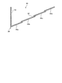
自動販売機は、例えば図9に示すように、商品を所定の温度状態で収容する箱状の収容庫1を備えている。収容庫1は、商品Pを陳列した状態で保持し、且つ保持している商品Pを個々に繰り出す複数の商品陳列棚2と、商品陳列棚2から繰り出された商品を受け取る受取棚3を有する商品搬送装置4とを備えている。   For example, as shown in FIG. 9, the vending machine includes a box-shaped storage 1 that stores products at a predetermined temperature. The container 1 has a plurality of product display shelves 2 that hold the products P in a displayed state, and individually feed the products P that are held, and a receiving shelf 3 that receives the products fed from the product display shelves 2. And a merchandise carrying device 4.

商品陳列棚2は、収容庫1の前後方向に沿って水平にそれぞれ配置されており、収容庫1の内部に段状に複数、配設してある。受取棚3は、収容庫1の内部において複数の商品陳列棚2の前方域に移動可能に配設してある。   The merchandise display shelves 2 are horizontally arranged along the front-rear direction of the storage 1, and a plurality of product display shelves 2 are arranged in a step shape inside the storage 1. The receiving shelf 3 is movably disposed in a front area of the plurality of product display shelves 2 inside the storage 1.

受取棚3は、商品載置部3aと回動軸3bとを備えるよう構成してある。商品載置部3aは、商品陳列棚2から繰り出された商品Pを載置する部分であって、収容庫1の前後方向に沿って水平に配置してある。回動軸3bは、受取棚3における商品陳列棚2に近接した端側に配設してある。   The receiving shelf 3 is configured to include a product placement portion 3a and a rotation shaft 3b. The product placement unit 3 a is a part on which the product P fed out from the product display shelf 2 is placed, and is placed horizontally along the front-rear direction of the container 1. The rotating shaft 3b is disposed on the end side of the receiving shelf 3 close to the commodity display shelf 2.

このような自動販売機は、任意の商品陳列棚2から商品を繰り出す場合、先ず、図9中、実線で示すように、商品Pの繰り出しを行う商品陳列棚2の前方域に受取棚3を移動した後、商品陳列棚2から商品Pを1つ繰り出し、繰り出した商品Pを受取棚3で受け取る。受け取った商品Pを、例えば商品載置部3aに横倒しの状態で載置しながら、受取棚3を下方へ移動することで商品Pを所定の払出位置へ向けて搬送する。その後、図9中、2点鎖線で示すように、収容庫1の下部の払出位置において、受取棚3における商品陳列棚2に離隔したが下方に向けて移動するよう、受取棚3を回動軸3bを中心に回動することで、受取棚3に載置した商品を払い出す。   When such a vending machine pays out a product from an arbitrary product display shelf 2, first, as shown by a solid line in FIG. 9, the receiving shelf 3 is placed in the front area of the product display shelf 2 where the product P is delivered. After the movement, one product P is delivered from the product display shelf 2, and the delivered product P is received by the receiving shelf 3. For example, the product P is transported toward a predetermined payout position by moving the receiving shelf 3 downward while placing the received product P on the product placement unit 3a in a lying state. Thereafter, as shown by a two-dot chain line in FIG. 9, the receiving shelf 3 is rotated so as to move downward while being separated from the product display shelf 2 in the receiving shelf 3 at the payout position in the lower part of the storage 1. The product placed on the receiving shelf 3 is paid out by rotating around the shaft 3b.

ところで、上記のような商品搬送装置において、図10に示すように、例えば商品陳列棚2に商品Pが引っ掛かることに起因して、商品陳列棚2から繰り出した商品Pが、商品陳列棚2および受取棚3の上に載置される場合がある。このような状態で、受取棚3を下方に向けて移動すると、商品Pが受取棚3から落下する問題があった。   By the way, in the product transport apparatus as described above, as shown in FIG. 10, for example, when the product P is caught on the product display shelf 2, the product P fed out from the product display shelf 2 is replaced with the product display shelf 2 and It may be placed on the receiving shelf 3. If the receiving shelf 3 is moved downward in such a state, there is a problem that the product P falls from the receiving shelf 3.

本発明は、上記に鑑みてなされたものであって、商品陳列棚から繰り出された商品を受取棚が受け取る際に、商品が受取棚から落下することを防止することができる商品搬送装置を提供することにある。   The present invention has been made in view of the above, and provides a merchandise conveying apparatus capable of preventing merchandise from falling from the receiving shelf when the receiving shelf receives the merchandise fed from the merchandise display shelf. There is to do.

上述した課題を解決し、目的を達成するために、本発明は、商品陳列棚の繰出口から繰り出された商品を受取棚の商品載置部に載置させ、受取棚を移動させることにより所定の払出位置まで搬送する商品搬送装置において、少なくとも商品陳列棚から商品を繰り出す場合に受取棚の商品載置部を商品陳列棚の繰出口から離隔するに従って漸次下方に傾斜させることを特徴とする。   In order to solve the above-described problems and achieve the object, the present invention sets the product fed from the delivery outlet of the product display shelf on the product placement unit of the receiving shelf and moves the receiving shelf to determine In the merchandise transporting apparatus that transports the merchandise to the payout position, at least when the merchandise is delivered from the merchandise display shelf, the merchandise placement section of the receiving shelf is gradually inclined downward as it is separated from the delivery outlet of the merchandise display shelf.

また、本発明の請求項2に係る商品搬送装置は、上記請求項1において、商品載置部の上面に凹凸を形成したことを特徴とする。   Moreover, the goods conveying apparatus which concerns on Claim 2 of this invention has formed the unevenness | corrugation in the upper surface of the goods mounting part in the said Claim 1. It is characterized by the above-mentioned.

また、本発明の請求項3に係る商品搬送装置は、上記請求項1または2において、商品載置部を傾斜させた状態で受取棚を払出位置まで移動させることを特徴とする。   According to a third aspect of the present invention, there is provided the commodity conveying apparatus according to the first or second aspect, wherein the receiving shelf is moved to the payout position in a state where the commodity placing portion is inclined.

また、本発明の請求項4に係る商品搬送装置は、上記請求項1〜3のいずれか一つにおいて、受取棚は、商品陳列棚から離隔した端部に上方に向けて立設するストッパ壁を備え、且つ払出位置においてこのストッパ壁の上端部が商品陳列棚に近接する態様で回動することにより商品載置部に載置した商品を払い出すことを特徴とする。   According to a fourth aspect of the present invention, there is provided the product conveying device according to any one of the first to third aspects, wherein the receiving shelf is erected upward at an end portion separated from the commodity display shelf. And the product placed on the product placement unit is paid out by rotating the upper end of the stopper wall close to the product display shelf at the delivery position.

また、本発明の請求項5に係る自動販売機は、商品を収容する収容庫の内部に請求項1〜4のいずれか一つに記載の商品搬送装置を備えることを特徴とする。   Moreover, the vending machine which concerns on Claim 5 of this invention is equipped with the goods conveyance apparatus as described in any one of Claims 1-4 inside the storage container which accommodates goods.

また、本発明の請求項6に係る自動販売機は、収容庫は、内部の空気を循環させる循環手段を備え、受取棚の商品載置部は、下面が待機状態において、収容庫の手前に行くに従って漸次下方に傾斜し、内部の空気を循環方向に案内することを特徴とする。   Further, in the vending machine according to claim 6 of the present invention, the storage is provided with a circulating means for circulating the air inside, and the product placement portion of the receiving shelf is in front of the storage when the lower surface is in a standby state. As it goes, it is gradually inclined downward and guides the air in the circulation direction.

本発明によれば、少なくとも商品陳列棚から商品を繰り出す場合に受取棚の商品載置部を商品陳列棚の繰出口から離隔するに従って漸次下方に傾斜させるため、例えば商品陳列棚に商品が引掛かかった場合でも、重力の作用で商品を商品陳列棚から商品を離隔させることができ、且つ受取棚に引き込むことができる。よって、商品陳列棚から繰り出された商品を受取棚が受け取る際に、商品が受取棚から落下することを防止することができる。   According to the present invention, at least when the product is delivered from the product display shelf, the product placement portion of the receiving shelf is gradually inclined downward as it is separated from the delivery port of the product display shelf. Even in such a case, the merchandise can be separated from the merchandise display shelf by the action of gravity, and can be pulled into the receiving shelf. Therefore, when the receiving shelf receives the product fed from the product display shelf, it is possible to prevent the product from dropping from the receiving shelf.

請求項2に係る商品搬送装置によれば、商品載置部の上面に凹凸を形成したため、凹凸によって受取棚と商品との間に隙間をつくり、受取棚に商品が張り付くことを防止することができる。   According to the commodity transporting apparatus according to claim 2, since the unevenness is formed on the upper surface of the commodity mounting portion, the unevenness creates a gap between the receiving shelf and the commodity, thereby preventing the commodity from sticking to the receiving shelf. it can.

請求項5に係る自動販売機によれば、商品を収容する収容庫の内部に請求項1〜4のいずれか一つに記載の商品搬送装置を備えるため、上述した効果を備える自動販売機を提供することができる。   According to the vending machine according to the fifth aspect, the vending machine having the above-described effect is provided in order to include the merchandise conveying device according to any one of the first to fourth aspects inside the container that accommodates the merchandise. Can be provided.

請求項6に係る自動販売機は、収容庫は、内部の空気を循環させる循環手段を備え、受取棚の商品載置部は、下面が待機状態において、収容庫の手前に行くに従って漸次下方に傾斜し、内部の空気を循環方向に案内するため、受取棚を空気の向きを変える整流板として使用することができる。従って、空気を循環させるために配設する整流板の数を減少させることができ、部品点数を削減することによって、安価な自動販売機を提供することができる。   In the vending machine according to claim 6, the container is provided with a circulation means for circulating the air inside, and the product placement portion of the receiving shelf is gradually lowered downward as it goes to the front of the container in the standby state. The receiving shelf can be used as a baffle plate that changes the direction of the air in order to incline and guide the air in the circulation direction. Therefore, the number of rectifying plates disposed for circulating air can be reduced, and an inexpensive vending machine can be provided by reducing the number of parts.

以下に添付図面を参照して、本発明に係る商品搬送装置を適用した自動販売機の好適な実施の形態について詳細に説明する。   Exemplary embodiments of a vending machine to which a commodity transport device according to the present invention is applied will be described below in detail with reference to the accompanying drawings.

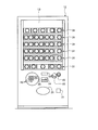
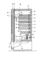
図1〜図3は、本発明に係る商品搬送装置を適用した自動販売機を示す図である。ここで例示する自動販売機は、後述する透明板および断熱透明部材を介して内部の商品を見ることができるビュータイプのものであって、複数種類の商品を陳列しながら販売するためのものであって、本体キャビネット10と外扉12とを備えている。商品としては、例えばカップ入りアイスクリームのように定形物として取り扱うことのできるものに限られず、袋入りアイスクリームのように定形物として取り扱うことが困難なものも対象としている。   1-3 is a figure which shows the vending machine to which the goods conveyance apparatus based on this invention is applied. The vending machine illustrated here is a view type that can see the products inside through a transparent plate and a heat insulating transparent member, which will be described later, and is for selling while displaying a plurality of types of products. The main body cabinet 10 and the outer door 12 are provided. The product is not limited to a product that can be handled as a regular product such as a cup of ice cream, but also a product that is difficult to handle as a regular product such as a bag of ice cream.

本体キャビネット10は、前面に開口を有する箱状に形成してある。外扉12は、本体キャビネット10の開口を閉塞する態様で揺動することが可能なよう一側縁部を介して本体キャビネット10に支持させたものである。   The main body cabinet 10 is formed in a box shape having an opening on the front surface. The outer door 12 is supported by the main body cabinet 10 through one side edge so as to be able to swing in a manner that closes the opening of the main body cabinet 10.

この外扉12には、その前面の上部から中央にわたる部位に透明板13を配設してあるとともに、その前面の下部に紙幣挿通口14、硬貨投入口15、返却レバー16、硬貨返却口17、表示器18、テンキー19、機能キー20、および商品取出口21を配設してある。   The outer door 12 is provided with a transparent plate 13 at a portion extending from the upper part of the front surface to the center, and a bill insertion port 14, a coin insertion port 15, a return lever 16, and a coin return port 17 at the lower part of the front surface. A display 18, a numeric keypad 19, a function key 20, and a product outlet 21 are provided.

透明板13は、後述する商品陳列棚に陳列してある商品を利用者が見ることができるよう外扉12に取り付けたものである。   The transparent plate 13 is attached to the outer door 12 so that the user can see the products displayed on the product display shelf described later.

紙幣挿通口14は、利用者が紙幣を挿入するための開口である。この紙幣挿通口14を通じて挿入された紙幣は、図示せぬ紙幣処理装置において適宜処理されることになる。なお、この紙幣挿通口14は、利用者に対して紙幣を返却する際の紙幣返却口としても機能する。硬貨投入口15は、利用者が硬貨を投入するための開口である。この硬貨投入口15を通じて投入された硬貨は、図示せぬ硬貨処理装置において適宜処理されることになる。返却レバー16は、紙幣挿通口14から挿入した紙幣、あるいは硬貨投入口15から投入した硬貨を返却する場合に操作するものであり、硬貨投入口15の近傍に配設してある。硬貨返却口17は、利用者に対して硬貨を返却するための開口であり、硬貨投入口15よりも下方となる位置に設けてある。表示器18は、貨幣の入金額、商品の販売中であるか否か、釣り銭があるか否か等々、商品を販売する上で必要となる各種情報を外部に表示するためのものであり、例えば液晶表示器によって構成してある。テンキー19および機能キー20は、商品の購入に関わる指示情報を入力するものであり、テンキー19が商品の選択に関わる情報を入力するものであり、機能キー20がテンキー19による入力を実行を指示したり、訂正を指示したりするものである。商品取出口21は、利用者が購入した商品を受け取るための開口であり、外扉12の下部に横長楕円状に形成してある。   The banknote insertion port 14 is an opening for a user to insert a banknote. The banknote inserted through the banknote insertion port 14 is appropriately processed in a banknote processing apparatus (not shown). In addition, this banknote insertion port 14 functions also as a banknote return port at the time of returning a banknote with respect to a user. The coin slot 15 is an opening through which a user inserts coins. The coins inserted through the coin insertion slot 15 are appropriately processed in a coin processing device (not shown). The return lever 16 is operated when returning a bill inserted from the bill insertion slot 14 or a coin inserted from the coin insertion slot 15, and is disposed in the vicinity of the coin insertion slot 15. The coin return port 17 is an opening for returning coins to the user, and is provided at a position below the coin insertion port 15. The indicator 18 is for displaying various information necessary for selling the product, such as the amount of money deposited, whether the product is being sold, whether there is a change, etc. For example, a liquid crystal display is used. The numeric keypad 19 and the function key 20 are used to input instruction information related to product purchase. The numeric keypad 19 is used to input information related to product selection. The function key 20 instructs execution of input using the numeric keypad 19. Or instructing correction. The product outlet 21 is an opening for receiving a product purchased by a user, and is formed in a horizontally long oval shape at the bottom of the outer door 12.

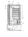
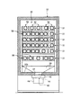
本体キャビネット10は、その内部に断熱材によって構成した収容庫30を有している。収容庫30は、箱状に形成してあって、複数段(本実施の形態では6段)の商品陳列棚31を備えており、商品陳列棚31に陳列する商品に応じた冷却状態に維持するよう構成してある。具体的には、収容庫30の内部において最下段に位置する商品陳列棚31よりも下方となる位置に冷却器33を有し、且つこの冷却器33の近傍に上方に向けて空気を送り出す不図示のファンとを備えており、この冷却器33およびファンを設定温度に応じて適宜駆動することにより商品を所望の温度状態に維持するよう構成してある。このような収容庫30の前面側には中扉35を配設してあり、収容庫30の底板30bには商品排出口37を配設してあり、収容庫30の下部には商品排出口37へと商品を案内する第1シュータ39を配設してある。   The main body cabinet 10 has the storage 30 comprised with the heat insulating material in the inside. The container 30 is formed in a box shape and includes a plurality of (in this embodiment, six) product display shelves 31 and is maintained in a cooled state corresponding to the products displayed on the product display shelves 31. It is configured to do. Specifically, a cooler 33 is provided at a position below the product display shelf 31 located at the lowermost stage in the container 30, and air is not sent out in the vicinity of the cooler 33 upward. The cooling fan 33 and the fan are appropriately driven in accordance with a set temperature to maintain the product in a desired temperature state. A middle door 35 is provided on the front side of the storage 30, a product discharge port 37 is provided on the bottom plate 30 b of the storage 30, and a product discharge port is provided below the storage 30. A first shooter 39 for guiding products to 37 is arranged.

中扉35は、揺動することが可能なよう一側縁部を介して収容庫30に支持させたものである。このような中扉35は、透明である例えばガラスを複数枚有するとともに、複数枚のガラスの間に断熱材である空気を充填することで形成した断熱透明部材36を備えており、その断熱透明部材36によって、自動販売機の外部から商品陳列棚31で陳列している商品を視認でき、且つ商品陳列棚31で陳列している商品を所望の温度状態に維持できるよう形成してある。   The middle door 35 is supported by the storage 30 via one side edge so that it can swing. Such an inner door 35 includes a plurality of transparent glasses, for example, and includes a heat insulating transparent member 36 formed by filling air as a heat insulating material between the plurality of glasses. The member 36 is formed so that the commodity displayed on the commodity display shelf 31 can be visually recognized from the outside of the vending machine, and the commodity displayed on the commodity display shelf 31 can be maintained at a desired temperature state.

上記収容庫30の下方には、扉体41と、扉体41を収容する収容体42と、扉体41を移動させるための不図示の駆動源とを備える扉体移動装置40を配設してある。   A door body moving device 40 including a door body 41, a housing body 42 that houses the door body 41, and a drive source (not shown) for moving the door body 41 is disposed below the housing 30. It is.

扉体移動装置40は、商品排出口37を通して収容庫30の内部と外部とが連通する開成状態(図2中、2点鎖線で示す)と、商品排出口37による収容庫30の内部と外部との連通を遮断する閉成状態(図2中、実線および破線で示す)とに扉体41を移動可能な態様で構成してある。扉体41は、例えば直方体状に形成してあって、内部に断熱材を充填してある。   The door body moving device 40 includes an open state (indicated by a two-dot chain line in FIG. 2) in which the inside and outside of the storage 30 communicate with each other through the product discharge port 37, and the inside and outside of the storage 30 by the product discharge port 37. The door body 41 is configured so as to be movable to a closed state (indicated by a solid line and a broken line in FIG. 2) that blocks communication with the door. The door body 41 is formed in a rectangular parallelepiped shape, for example, and is filled with a heat insulating material.

このような扉体移動装置40の作用を説明する。扉体移動装置40は、商品排出口37を通して収容庫30に空気が出入りし、それにより収容庫30の温度状態が変化することを防止するため、通常、扉体41を閉成状態に移動させてある。利用者が貨幣を入れ、且つテンキー19および機能キー20を利用者が操作した場合には、後述する商品搬送装置80の駆動に応じて扉体41を開成状態に変位させ、収容庫30の内部の商品が商品排出口37を通して収容庫30の外部に排出されることを許容する。収容庫30の外部に商品が排出された後、扉体移動装置40は、扉体41を閉成状態に移動させる。   The operation of the door moving device 40 will be described. The door body moving device 40 normally moves the door body 41 to a closed state in order to prevent air from entering and exiting the container 30 through the product discharge port 37 and thereby changing the temperature state of the container 30. It is. When the user inserts money and the user operates the numeric keypad 19 and the function key 20, the door body 41 is displaced to the open state in accordance with the driving of the commodity conveying device 80 described later, and the inside of the storage 30 This product is allowed to be discharged to the outside of the container 30 through the product discharge port 37. After the commodity is discharged to the outside of the container 30, the door body moving device 40 moves the door body 41 to the closed state.

本体キャビネット10の内部であって扉体移動装置40の下方には、商品排出口37から排出された商品を、商品取出口21の下方へと案内する第2シュータ44を配設してある。   Inside the main body cabinet 10 and below the door body moving device 40, a second shooter 44 that guides the product discharged from the product discharge port 37 to the lower side of the product outlet 21 is disposed.

商品陳列棚31は、個々の上面に複数のスパイラルラック50を備えており、それらのスパイラルラック50から商品を繰り出すことで、商品の繰り出しを行うものとしても機能する。本実施の形態では、最上段の商品陳列棚31は5つのスパイラルラック50を有しており、上から2番目の商品陳列棚31、上から3番目の商品陳列棚31、および上から4番目の商品陳列棚31は4つのスパイラルラック50を備えており、上から5番目の商品陳列棚31は5つのスパイラルラック50をそれぞれ有している。各商品陳列棚31は、収容庫30の左右幅よりもわずかに狭い幅を有し、且つ収容庫30に対して手前側に引き出せるよう配設してあり、収容庫30の前後方向に沿って水平にそれぞれ配置されている。なお、上記5つの商品陳列棚31のうち、最下段の商品陳列棚31は、前後方向の長さが、他の商品陳列棚31の前後方向の長さに比して短く形成してあり、後述する払出位置において搬送棚を回動する際に、最下段の商品陳列棚31と搬送棚との間で商品が詰まることを防止してある。   The product display shelf 31 includes a plurality of spiral racks 50 on each upper surface, and functions as a product that is delivered by delivering the product from the spiral racks 50. In the present embodiment, the uppermost product display shelf 31 has five spiral racks 50, the second product display shelf 31 from the top, the third product display shelf 31 from the top, and the fourth from the top. The product display shelf 31 includes four spiral racks 50, and the fifth product display shelf 31 from the top includes five spiral racks 50, respectively. Each merchandise display shelf 31 has a width that is slightly narrower than the lateral width of the storage case 30 and is arranged so as to be pulled out toward the front side with respect to the storage case 30, along the front-rear direction of the storage case 30. They are arranged horizontally. Of the five product display shelves 31, the lowermost product display shelf 31 has a length in the front-rear direction that is shorter than the length in the front-rear direction of the other product display shelves 31. When the transport shelf is rotated at a payout position described later, the product is prevented from being jammed between the lowermost product display shelf 31 and the transport shelf.

スパイラルラック50は、商品陳列棚31の左右方向に列状となる態様で並設されており、販売すべき商品を保持するとともに、個々に送信される販売指令に基づいて商品を繰り出すものである。この実施の形態に示すスパイラルラック50には、後述する商品保持棒52を1本備えたシングルスパイラルラックと、商品保持棒52を2本備えたダブルスパイラルラックとを備えている。以下、スパイラルラック50の説明としてダブルスパイラルラックを用いて説明する。スパイラルラック50は、図4に示すように、コラムケース51と商品保持棒52とガイド手段55と駆動手段60とで構成してある。   The spiral racks 50 are arranged side by side in a row form in the left-right direction of the product display shelf 31, hold the products to be sold, and deliver the products based on individually transmitted sales instructions. . The spiral rack 50 shown in this embodiment includes a single spiral rack provided with one commodity holding bar 52 described later and a double spiral rack provided with two commodity holding bars 52. Hereinafter, the spiral rack 50 will be described using a double spiral rack. As shown in FIG. 4, the spiral rack 50 includes a column case 51, a product holding bar 52, guide means 55, and drive means 60.

コラムケース51は、上面、前面、および後面が開口し、収容庫30の前後方向に延在する箱状に形成してある。このようなコラムケース51の前面の開口は、商品の繰り出しを行う繰出口として機能する。一方、コラムケース51の後面の開口は、駆動手段60の動力ボックス61によって閉塞してある。   The column case 51 has an upper surface, a front surface, and a rear surface that are open, and is formed in a box shape that extends in the front-rear direction of the container 30. Such an opening on the front surface of the column case 51 functions as a delivery outlet for delivering products. On the other hand, the opening on the rear surface of the column case 51 is closed by a power box 61 of the driving means 60.

商品保持棒52は、コラムケース51の内部であって、収容庫30の前後方向に延在するスパイラル軸53に沿った螺旋状に形成してある。具体的には、一方の商品保持棒52は、自動販売機の前面側から見て、反時計回りの螺旋状になるよう形成してあり、他方の商品保持棒52は、時計回りの螺旋状になるよう形成してある。各商品保持棒52は、自動販売機の正面側から見て1回転する長さ(1ピッチ)に相当する部位に、上記商品Pを1つ保持する保持空間52aを有している。換言すれば、各商品保持棒52は、1ピッチ毎に商品Pを1つ保持する保持空間52aを複数有している。   The product holding rod 52 is formed in a spiral shape along the spiral shaft 53 that extends in the front-rear direction of the storage case 30 inside the column case 51. Specifically, one product holding bar 52 is formed to have a counterclockwise spiral shape when viewed from the front side of the vending machine, and the other product holding bar 52 has a clockwise spiral shape. It is formed to become. Each product holding bar 52 has a holding space 52a for holding one product P at a portion corresponding to a length (one pitch) of one rotation when viewed from the front side of the vending machine. In other words, each product holding bar 52 has a plurality of holding spaces 52a for holding one product P for each pitch.

ガイド手段55は、後述する商品保持棒52の繰り出の際に、商品保持棒52が収容庫30の左右方向に移動することを防止するものであって、ガイドレール56と、案内部材57と固定板58とを備えている。ガイドレール56は、一方の端をコラムケース51の先端に取り付けてあり、他方の端をコラムケース51の基端側に配設してある固定板58に取り付けてあるものであって、スパイラル軸53に沿う態様で、且つスパイラル軸53の下方領域に配設してある。案内部材57は、コラムケース51と商品保持棒52との間であって、商品保持棒52を挟み込むよう2つで1対を成す態様で配設してある。固定板58は、円板状に形成してあって、中央にピン挿入孔をそれぞれ有している。   The guide means 55 prevents the product holding bar 52 from moving in the left-right direction of the storage case 30 when the product holding bar 52 to be described later is extended, and includes a guide rail 56, a guide member 57, and the like. And a fixed plate 58. The guide rail 56 has one end attached to the distal end of the column case 51 and the other end attached to a fixed plate 58 disposed on the proximal end side of the column case 51, and has a spiral shaft. 53 and arranged in the lower region of the spiral shaft 53. The guide member 57 is disposed between the column case 51 and the product holding bar 52 in such a manner that a pair is formed so as to sandwich the product holding bar 52 therebetween. The fixed plate 58 is formed in a disc shape and has a pin insertion hole in the center.

駆動手段60は、動力ボックス61と駆動源62と駆動伝達機構63とで構成してある。動力ボックス61は、駆動源62および駆動伝達機構63を覆うケースである。駆動源62は、駆動状態に成した場合に回転駆動する駆動軸を有している。このような駆動源62としては、例えばサーボモータを用いてある。駆動伝達機構63は、駆動源62の回転駆動力を商品保持棒52に伝達するものであって、駆動軸に取り付けた駆動ギア64と、駆動ギア64に歯合した第1中間ギア65と、第1中間ギア65に歯合した第2中間ギア66と、第1中間ギア65に歯合した第1従動ギア67と、第2中間ギア66に歯合した第2従動ギア68と、第1従動ギア67に一方の端を固着した第1連結ピン69と、第1連結ピン69の他方の端に固着した第1回転板70と、第2従動ギア68に一方の端を固着した第2連結ピン71と、第2連結ピン71の他方の端に固着した第2回転板72とを備えている。連結ピン69,71の他方の端は、回動自在な態様で上記固定板58のピン挿入孔にそれぞれ挿入してある。第1回転板70および第2回転板72には、上記商品保持棒52の一方の端をそれぞれ取り付けてある。   The drive means 60 includes a power box 61, a drive source 62, and a drive transmission mechanism 63. The power box 61 is a case that covers the drive source 62 and the drive transmission mechanism 63. The drive source 62 has a drive shaft that rotates when driven. As such a drive source 62, for example, a servo motor is used. The drive transmission mechanism 63 transmits the rotational driving force of the drive source 62 to the product holding rod 52, and includes a drive gear 64 attached to the drive shaft, a first intermediate gear 65 meshed with the drive gear 64, A second intermediate gear 66 meshed with the first intermediate gear 65; a first driven gear 67 meshed with the first intermediate gear 65; a second driven gear 68 meshed with the second intermediate gear 66; A first connecting pin 69 with one end fixed to the driven gear 67, a first rotating plate 70 fixed to the other end of the first connecting pin 69, and a second connecting one end to the second driven gear 68. A connecting pin 71 and a second rotating plate 72 fixed to the other end of the second connecting pin 71 are provided. The other ends of the connecting pins 69 and 71 are inserted into the pin insertion holes of the fixing plate 58 in a rotatable manner. One end of the product holding bar 52 is attached to each of the first rotating plate 70 and the second rotating plate 72.

このように構成してあるスパイラルラック50の作用を説明する。利用者が貨幣を入れ、且つテンキー19および機能キー20を利用者が操作することで、商品Pの繰り出しを行う場合には、先ず、駆動源62を駆動状態と成して駆動軸を回転駆動する。その駆動軸の回転駆動により、駆動ギア64が回転する。その駆動ギア64の回転により、中間ギア65,66を介して従動ギア67,68が回転することとなる。従動ギア67,68が回転すると、その回転に伴って回転板70,72が回転し、回転板70,72の回転に伴って商品保持棒52もスパイラル軸53を中心に回転することとなる。そのような商品保持棒52の回転によって、商品保持棒52で保持されていた商品Pがスパイラルラック50の前方の領域に繰り出されることとなる。商品保持棒52が1ピッチに相当する分だけ回転すると、駆動源62を停止し、それによりギア64,65,66,67,68の回転、回転板70,72の回転、および商品保持棒52の回転も停止することとなる。このような商品Pの繰り出しは、利用者が貨幣を入れ、且つ利用者がキー19,20を操作するたびに行われる。   The operation of the spiral rack 50 thus configured will be described. When the user inserts money and the user operates the numeric keypad 19 and the function key 20 to feed the product P, first, the drive source 62 is set in the drive state to drive the drive shaft to rotate. To do. The drive gear 64 is rotated by the rotational drive of the drive shaft. Due to the rotation of the drive gear 64, the driven gears 67 and 68 are rotated via the intermediate gears 65 and 66. When the driven gears 67 and 68 rotate, the rotating plates 70 and 72 rotate with the rotation, and the product holding rod 52 also rotates about the spiral shaft 53 with the rotation of the rotating plates 70 and 72. By such rotation of the product holding bar 52, the product P held by the product holding bar 52 is fed out to an area in front of the spiral rack 50. When the product holding bar 52 rotates by an amount corresponding to one pitch, the drive source 62 is stopped, thereby rotating the gears 64, 65, 66, 67, 68, rotating the rotating plates 70, 72, and the product holding bar 52. Will also stop rotating. Such delivery of the product P is performed each time the user inserts money and the user operates the keys 19 and 20.

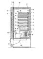
また、収容庫30の内部には、図5に示す商品搬送装置80を設けてある。商品搬送装置80は、最上段の商品陳列棚31のスパイラルラック50、上から2段目の商品陳列棚31のスパイラルラック50、上から3段目の商品陳列棚31のスパイラルラック50、上から4段目の商品陳列棚31のスパイラルラック50、および上から5段目の商品陳列棚31のスパイラルラックか50らから繰り出された商品Pを受け取り、当該商品Pを収容庫30の下部の払出位置Zに向けて搬送するものであって、搬送棚駆動手段81と搬送棚90とで構成してある。   In addition, a commodity transporting device 80 shown in FIG. The product conveying device 80 includes a spiral rack 50 of the uppermost product display shelf 31, a spiral rack 50 of the second product display shelf 31 from the top, and a spiral rack 50 of the third product display shelf 31 from the top. Receives the product P fed from the spiral rack 50 of the fourth-stage product display shelf 31 and the spiral rack 50 of the fifth-stage product display shelf 31 from the top, and delivers the product P to the lower part of the storage 30 It is transported toward the position Z, and is composed of a transport shelf driving means 81 and a transport shelf 90.

搬送棚駆動手段81は、左右一対の側板82と、それらの側板82の間に配設した天板83と、それぞれの側板82に配設した昇降用チェーン84と、各昇降用チェーン84に配設したバランサ85とを備えて構成してある。   The transport shelf driving means 81 is arranged on a pair of left and right side plates 82, a top plate 83 disposed between the side plates 82, a lifting chain 84 disposed on each side plate 82, and each lifting chain 84. The balancer 85 is provided.

天板83および側板82は、搬送棚駆動手段81のベースとなるものであって、天板83は収容庫30の天壁に沿って左右方向に延設してあり、側板82は収容庫30の側壁に沿って上下方向に延設してある。   The top plate 83 and the side plate 82 serve as a base for the transport shelf driving means 81, and the top plate 83 extends in the left-right direction along the top wall of the storage 30, and the side plate 82 is the storage 30. It is extended in the up-down direction along the side wall.

昇降用チェーン84は、それぞれ対応する側板82の上下両端部に配設した一対の昇降用スプロケット86の間に張り渡してある。各側板82の上端部に配設した昇降用スプロケット86は、左右方向に沿って配設した昇降用駆動軸87によって互いに連結してある。この昇降用駆動軸87は、昇降用モータ88に連係させたもので、該昇降用モータ88が駆動した場合に回転し、側板82のそれぞれの上端部に配設した昇降用スプロケット86を同一方向に回転させるものである。バランサ85は、それぞれが搬送棚90の重量のほぼ半分となる重量を有するように構成したもので、昇降用チェーン84の外周部に固着してある。また、昇降用チェーン84には、上記バランサ85と対称となる位置に、後述する搬送棚90の側壁91に連結させる支持板89を固着してある。図5からも明らかなように、バランサ85は、搬送棚90が水平となるよう左右で互いに同一となる位置に固着してある。   The elevating chains 84 are stretched between a pair of elevating sprockets 86 disposed at the upper and lower ends of the corresponding side plate 82. The elevating sprockets 86 arranged at the upper ends of the side plates 82 are connected to each other by elevating drive shafts 87 arranged along the left-right direction. The elevating drive shaft 87 is linked to the elevating motor 88 and rotates when the elevating motor 88 is driven, and the elevating sprockets 86 disposed on the upper ends of the side plates 82 are in the same direction. It is intended to rotate. Each balancer 85 is configured to have a weight that is approximately half of the weight of the transport shelf 90, and is fixed to the outer peripheral portion of the lifting chain 84. Further, a support plate 89 to be connected to a side wall 91 of a transport shelf 90 described later is fixed to the lifting chain 84 at a position symmetrical to the balancer 85. As is clear from FIG. 5, the balancer 85 is fixed at the same position on the left and right so that the transport shelf 90 is horizontal.

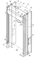
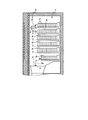
搬送棚90は、スパイラルラック50から繰り出された商品Pを受け取る受取棚として機能するものであるとともに、受け取った商品Pを払出位置Zに向けて下方に搬送する機能も有するものであり、左右幅方向の両端部にそれぞれ側壁91を備えるとともに、これらの側壁91の間に配設し、商品載置部92と商品払出部93とを有する受台94を備えるよう構成したものであって、商品陳列棚31の左右方向に並べたすべてのスパイラルラック50の左右方向の幅を合算した幅を有するものである。換言すれば、搬送棚90は、収容庫30の左右方向の幅よりもわずかに狭い幅を有するものである。   The transport shelf 90 functions as a receiving shelf for receiving the product P fed from the spiral rack 50, and also has a function of transporting the received product P downward toward the payout position Z. Both end portions in the direction are provided with side walls 91, disposed between these side walls 91, and configured to include a receiving base 94 having a product placing portion 92 and a product dispensing portion 93. The total width of the spiral racks 50 arranged in the left-right direction of the display shelf 31 is the sum of the widths in the left-right direction. In other words, the conveyance shelf 90 has a width slightly narrower than the width of the storage case 30 in the left-right direction.

受台94は、例えば第1板状部材94aと第2板状部材94bと第3板状部材94cと第4板状部材94dとで構成してある。   The cradle 94 includes, for example, a first plate member 94a, a second plate member 94b, a third plate member 94c, and a fourth plate member 94d.

第1板状部材94aは横断面がレ字状となるよう透明な樹脂材料を押出成形によって形成したものであり、第2板状部材94b、第3板状部材94c、および第4板状部材94dは横断面が平板状となるよう透明な樹脂材料を押出成形によってそれぞれ形成したものである。   The first plate member 94a is formed by extrusion molding a transparent resin material so that the cross section has a letter shape. The second plate member 94b, the third plate member 94c, and the fourth plate member. 94d is formed by extrusion molding transparent resin materials so that the cross section is flat.

商品載置部92は、第1板状部材94aの一部と第2板状部材94bと第3板状部材94cと第4板状部材94dとで形成してあり、収容庫30の奥側の端に対して、収容庫30の手前側の端が下方となるよう傾斜する態様で配置してある部分である。換言すれば、商品載置部92は、スパイラルラック50から繰り出された商品Pを、商品陳列棚31に近接する部位が上方となり、且つ商品陳列棚31に離隔する部位が下方となるように傾斜した状態で載置する部分である。このような商品載置部92は、表面に凹凸が形成されるよう第1板状部材94aの後端部、第2板状部材94bの前後方向の端部、第3板状部材94cの前後方向の端部、および第4板状部材94dの前端部を相互に連結して形成される部分でもある。   The product placement portion 92 is formed by a part of the first plate-like member 94a, the second plate-like member 94b, the third plate-like member 94c, and the fourth plate-like member 94d, and the rear side of the storage 30 It is the part arrange | positioned with the aspect which inclines so that the edge of the near side of the storage container 30 may become the lower side with respect to this edge. In other words, the product placement unit 92 tilts the product P fed out from the spiral rack 50 so that the part close to the product display shelf 31 is upward and the part separated from the product display shelf 31 is downward. It is a part to be placed in the state. Such a product placement portion 92 has a rear end portion of the first plate-like member 94a, an end portion in the front-rear direction of the second plate-like member 94b, and a front-rear direction of the third plate-like member 94c so that irregularities are formed on the surface. It is also a portion formed by mutually connecting the end portion in the direction and the front end portion of the fourth plate-like member 94d.

商品払出部93は、第1板状部材94aの一部によって形成してあり、商品載置部92で載置している商品Pが、受台94の手前側から落下することを防止するストッパ壁として機能する部分であるとともに、後述する払い出し時に商品載置部92から確実に商品Pを払い出す部分であり、表面および裏面が上下方向に沿うよう配置してある。このように配置した商品払出部93は、搬送棚90における商品陳列棚31から離隔した端部に上方に向けて立設している。   The product dispensing part 93 is formed by a part of the first plate-like member 94a, and a stopper that prevents the product P placed on the product placing part 92 from dropping from the front side of the receiving base 94. In addition to being a part that functions as a wall, it is a part that reliably delivers the product P from the product placement part 92 when the product is dispensed, which will be described later, and the front and back surfaces are arranged along the vertical direction. The product delivery section 93 arranged in this manner is erected upward at an end portion of the transport shelf 90 that is separated from the product display shelf 31.

搬送棚90の側壁91と、搬送棚駆動手段81の側板82との間には、搬送棚案内手段96をそれぞれ配設してある。搬送棚案内手段96は、案内板取付板97と第1ローラ98と第2ローラ99と第1ローラ案内板100と第2ローラ案内板101とを備えている。案内板取付板97は、上記第1ローラ案内板100および第2ローラ案内板101を取り付けるものであって、上記搬送棚駆動手段81の側板82と同一の間隔で、且つ側板82の手前側にそれぞれ取り付けてある。   Between the side wall 91 of the conveyance shelf 90 and the side plate 82 of the conveyance shelf driving means 81, a conveyance shelf guide means 96 is disposed. The conveyance shelf guide means 96 includes a guide plate mounting plate 97, a first roller 98, a second roller 99, a first roller guide plate 100, and a second roller guide plate 101. The guide plate mounting plate 97 is used to mount the first roller guide plate 100 and the second roller guide plate 101, and is at the same interval as the side plate 82 of the transport shelf driving means 81 and on the front side of the side plate 82. Each is attached.

第1ローラ98および第2ローラ99は、搬送棚90の側壁91に回動自在に取り付けてある。より具体的には、第1ローラ98および第2ローラ99は、搬送棚90の側壁91の対向する面と反対の面に、回動自在に取り付けてある。第1ローラ98は、収容庫30の手前側に配置してあり、第2ローラ99は、第1ローラ98よりも収容庫30の奥側であって、例えば第1ローラ98よりも下方に配置してある。   The 1st roller 98 and the 2nd roller 99 are attached to the side wall 91 of the conveyance shelf 90 so that rotation is possible. More specifically, the first roller 98 and the second roller 99 are rotatably attached to a surface opposite to the facing surface of the side wall 91 of the transport shelf 90. The first roller 98 is disposed on the front side of the storage case 30, and the second roller 99 is disposed on the rear side of the storage case 30 with respect to the first roller 98, for example, below the first roller 98. It is.

第1ローラ案内板100は、2枚の板材で一組を成すよう構成してあり、それらの板材を、第1ローラ98の直径に対応する間隔を保持しながら上下方向に延在するよう上記側板82の手前側に取り付けてある。   The first roller guide plate 100 is configured to form a pair of two plate materials, and the plate materials extend in the vertical direction while maintaining a distance corresponding to the diameter of the first roller 98. It is attached to the front side of the side plate 82.

第2ローラ案内板101は、2枚の板材で一組を成すよう構成してあり、それらの板材を、第2ローラ99の直径に対応する間隔を保持しながら上下方向に延在し、且つ例えば最下段の商品陳列棚31の前方域にある部位では収容庫30の手前側に向けて弧を描く態様で折れ曲がるよう上記側板82の奥側に取り付けてある。より具体的には、第2ローラ案内板101は、最下段の商品陳列棚31の前方域にある部位であって、商品の払出位置Zでは、収容庫30の手前側に向けて回動軸102aを中心とする弧を描く態様で折れ曲がるよう側板82に取り付けてある。   The second roller guide plate 101 is configured to form a pair of two plate materials, and these plate materials extend in the vertical direction while maintaining a distance corresponding to the diameter of the second roller 99, and For example, in the region in the front area of the lowermost product display shelf 31, it is attached to the back side of the side plate 82 so as to be bent in a manner of drawing an arc toward the front side of the container 30. More specifically, the second roller guide plate 101 is a portion in the front area of the lowermost product display shelf 31, and is a rotating shaft toward the front side of the container 30 at the product payout position Z. It is attached to the side plate 82 so as to be bent in a manner of drawing an arc centering on 102a.

上記支持板89と、搬送棚90の側壁91とは、不図示のピンによって支持板89に対して側壁91が回転可能な態様で連結してある。換言すれば、搬送棚90を支持板89に対して回転可能な態様で連結してある。   The support plate 89 and the side wall 91 of the transport shelf 90 are connected to the support plate 89 in such a manner that the side wall 91 can rotate with a pin (not shown). In other words, the transport shelf 90 is connected to the support plate 89 in a manner that allows rotation.

このような構成を有する搬送棚駆動手段81では、昇降用モータ88を駆動することによって昇降用駆動軸87を回転させると、昇降用スプロケット86を介して昇降用チェーン84が適宜方向に周回し、昇降用チェーン84の周回に伴ってローラ案内板100,101でローラ98,99が案内されて搬送棚90が5つの商品陳列棚31の前方域を上下方向に移動することとなる。より詳細には、ローラ案内板100,101が上下方向に延在する部位をローラ98,99が移動する場合には、搬送棚90の姿勢が維持されながら、上下方向に移動する。一方、搬送棚90を移動させることで、第2ローラ案内板101が収容庫30の手前側に向けて折れ曲がれる部位にまで第2ローラ99が移動すると、搬送棚90における商品陳列棚31に近接した端側を下方に向けて移動する態様で、回動軸102aを中心に回動し、商品払出部93の表面が略水平になるまで回動することとなる。   In the transport shelf driving means 81 having such a configuration, when the lifting drive shaft 87 is rotated by driving the lifting motor 88, the lifting chain 84 circulates in an appropriate direction via the lifting sprocket 86, The rollers 98 and 99 are guided by the roller guide plates 100 and 101 as the elevating chain 84 circulates, and the transport shelf 90 moves in the vertical direction in the front area of the five product display shelves 31. More specifically, when the rollers 98 and 99 move along the portion where the roller guide plates 100 and 101 extend in the vertical direction, they move in the vertical direction while maintaining the posture of the transport shelf 90. On the other hand, when the second roller 99 is moved to a position where the second roller guide plate 101 is bent toward the front side of the container 30 by moving the transport shelf 90, the transport shelf 90 approaches the product display shelf 31. In such a manner that the end side is moved downward, it is rotated about the rotation shaft 102a, and is rotated until the surface of the product dispensing portion 93 becomes substantially horizontal.

このような商品搬送装置80の搬送棚90は、図2に示すように、商品陳列棚31の前方域の上方であって、収容庫30の上部を待機位置とするものである。この状態では、商品載置部92の手前側の端が、商品載置部92の奥側の端よりも下方となるよう傾斜する態様、換言すれば、収容庫30の手前側に行くに従って漸次下方に傾斜する態様で配置されることとなる。この状態において、図2中、矢印で示すように、冷却器33によって冷却された空気は、ファンによって後方に向けて排出された後、収容庫30の背面側の側板と商品陳列棚31との間に構成された空気ダクト32を通って収容庫の上部に到達し、その後、不図示の整流板に当たって手前側に向けて移動することとなる。手前側に向けて移動した空気は、商品載置部92の裏面に当たり、下方に向けて移動することとなる。このように、冷却器33から排出された空気は、整流板および搬送棚90の商品載置部92によって収容庫30の内部を循環する。   As shown in FIG. 2, the conveyance shelf 90 of such a commodity conveyance device 80 is located above the front area of the commodity display shelf 31 and has the upper portion of the storage 30 as a standby position. In this state, an aspect in which the end on the near side of the product placement portion 92 is inclined to be lower than an end on the back side of the product placement portion 92, in other words, gradually toward the near side of the container 30. It will be arrange | positioned in the aspect inclined below. In this state, as indicated by an arrow in FIG. 2, the air cooled by the cooler 33 is exhausted rearward by the fan, and thereafter, the side plate on the back side of the storage 30 and the product display shelf 31. It reaches the upper part of the storage through the air duct 32 formed therebetween, and then moves toward the near side by hitting a current plate (not shown). The air that has moved toward the near side hits the back surface of the product placement section 92 and moves downward. In this way, the air discharged from the cooler 33 circulates inside the storage 30 by the current plate and the product placement portion 92 of the transport shelf 90.

また、例えば最上段の商品陳列棚31のスパイラルラック50に商品Pの繰り出し命令が送信された場合には、スパイラルラック50による商品Pの繰り出しに先んじて、図7に示すように、待機位置で待機している搬送棚90が最上段の商品陳列棚31の前方域に移動する。   Further, for example, when a product P delivery command is transmitted to the spiral rack 50 of the uppermost product display shelf 31, prior to delivery of the product P by the spiral rack 50, as shown in FIG. The waiting transport shelf 90 moves to the front area of the uppermost product display shelf 31.

その後、スパイラルラック50の繰出口から商品Pが1つ繰り出される。スパイラルラック50から繰り出された商品Pは、商品陳列棚31の繰出口から離隔するに従って下方に傾斜した上記搬送棚90の商品載置部92が受け取る。   Thereafter, one product P is fed out from the outlet of the spiral rack 50. The product P delivered from the spiral rack 50 is received by the product placement unit 92 of the transport shelf 90 that is inclined downward as it is separated from the delivery outlet of the product display shelf 31.

その後、搬送棚90は、姿勢を維持したまま収容庫30の下方に移動する。このように姿勢を維持したまま搬送棚90を移動するため、商品Pは、商品陳列棚31に近接する部位が上方となり、且つ商品陳列棚31に離隔する部位が下方となるように傾斜した状態を維持したまま収容庫30の下方の払出位置Zに搬送される。換言すれば、商品搬送装置80は、商品載置部92を傾斜させた状態で搬送棚90を払出位置Zまで移動させる。搬送棚90が払出位置Zまで移動し、第2ローラ案内板101が収容庫30の手前側に向けて折れ曲がれる部位にまで第2ローラ99が移動すると、搬送棚90は、回動軸102aを中心に、図8中、時計回りに回動する。すなわち、搬送棚90は、払出位置Zにおいて、商品払出部93の上端が商品陳列棚31に近接する態様で回動する。この回動により商品載置部92に載置した商品Pが搬送棚90から払い出されることとなる。搬送棚90は、商品払出部93の表面が略水平になるまで回動する。しかも、商品Pの払い出しにタイミングを合わせて扉体41を閉成状態から開成状態に移動させ、払い出された商品Pを商品排出口37を通して商品取出口21の下方まで移動させる。   Thereafter, the transport shelf 90 moves below the storage 30 while maintaining the posture. In order to move the transport shelf 90 while maintaining the posture in this way, the product P is inclined so that the part close to the product display shelf 31 is upward and the part separated from the product display shelf 31 is downward Is conveyed to the payout position Z below the container 30. In other words, the product conveyance device 80 moves the conveyance shelf 90 to the payout position Z in a state where the product placement unit 92 is inclined. When the transport shelf 90 moves to the payout position Z and the second roller 99 moves to a position where the second roller guide plate 101 is bent toward the front side of the storage 30, the transport shelf 90 moves the rotating shaft 102a. In the center, it rotates clockwise in FIG. In other words, the transport shelf 90 rotates at the payout position Z in such a manner that the upper end of the product payout portion 93 is close to the product display shelf 31. By this rotation, the product P placed on the product placement unit 92 is paid out from the transport shelf 90. The conveyance shelf 90 rotates until the surface of the product dispensing unit 93 becomes substantially horizontal. In addition, the door body 41 is moved from the closed state to the open state in time with the delivery of the product P, and the delivered product P is moved to the lower part of the product outlet 21 through the product discharge port 37.

この商品搬送装置80によれば、商品陳列棚31から商品Pを繰り出す場合に搬送棚90の商品載置部92を商品陳列棚31の繰出口から離隔するに従って漸次下方に傾斜させるため、例えば商品陳列棚31に商品Pが引掛かかった場合でも、重力の作用で商品Pを商品陳列棚31から商品Pを離隔させることができ、且つ搬送棚90に引き込むことができる。よって、商品陳列棚31および搬送棚90の上に商品Pが載置されることを防止することができ、それにより商品Pが搬送棚90から落下することを防止することができる。しかも、商品載置部92を傾斜させた状態で搬送棚90を払出位置Zまで移動させるため、商品Pを傾斜した状態で搬送し、商品Pの大きさに合わせて搬送棚90を形成する必要がなく、収容庫30の小型化を図ることができる。加えて、搬送棚90は、商品載置部92の上面に凹凸を形成してあるため、凹凸によって搬送棚90と商品Pとの間に隙間をつくり、搬送棚90に商品Pが張り付くことを防止することができる。さらに、この自動販売機によれば、搬送棚90の商品載置部92は、下面が待機状態において、収容庫30の手前側に行くに従って漸次下方に傾斜し、内部の空気を循環方向に案内するため、搬送棚90によって収容庫30の内部の空気を循環させることができる。従って、空気を循環させるために配設する整流板の数を減少させることができ、部品点数を削減することによって、安価な自動販売機を提供することができる。   According to the product transport device 80, when the product P is delivered from the product display shelf 31, the product placement portion 92 of the transport shelf 90 is gradually inclined downward as the product placement unit 92 is separated from the delivery outlet of the product display shelf 31, Even when the product P is caught on the display shelf 31, the product P can be separated from the product display shelf 31 by the action of gravity, and can be pulled into the transport shelf 90. Therefore, it is possible to prevent the product P from being placed on the product display shelf 31 and the transport shelf 90, thereby preventing the product P from falling from the transport shelf 90. Moreover, in order to move the transport shelf 90 to the payout position Z with the product placement portion 92 inclined, it is necessary to transport the product P in an inclined state and form the transport shelf 90 according to the size of the product P. Therefore, the storage 30 can be downsized. In addition, since the transport shelf 90 has irregularities formed on the upper surface of the product placement unit 92, a gap is formed between the transport shelf 90 and the product P due to the unevenness, and the product P sticks to the transport shelf 90. Can be prevented. Furthermore, according to this vending machine, the product placement section 92 of the transport shelf 90 is gradually inclined downward as it goes to the front side of the container 30 when the lower surface is in a standby state, and guides the internal air in the circulation direction. Therefore, the air inside the storage 30 can be circulated by the transport shelf 90. Therefore, the number of rectifying plates disposed for circulating air can be reduced, and an inexpensive vending machine can be provided by reducing the number of parts.

なお、上記自動販売機において、上から6段目の商品陳列棚31のスパイラルラック50から繰り出された商品Pは、第1シュータ39を介して直接、商品排出口37に向けて落下する。   In the vending machine, the product P fed out from the spiral rack 50 of the product display shelf 31 in the sixth row from the top falls directly toward the product discharge port 37 through the first shooter 39.

また、上述した実施の形態には、複数の板状部材94a,94b,94c,94dを連結することによって表面に凹凸を形成する搬送棚90を用いて説明した。しかし、この発明はそれに限られず、例えばエンボス加工等を施すことによって、搬送棚90の商品Pを載置する部位に凹凸を形成しても良い。   Further, in the above-described embodiment, the description has been given using the conveyance shelf 90 that forms the unevenness on the surface by connecting the plurality of plate-like members 94a, 94b, 94c, 94d. However, the present invention is not limited to this, and unevenness may be formed in a portion of the transport shelf 90 where the product P is placed by, for example, embossing.

本発明に係る商品搬送装置を適用した自動販売機を示す正面図である。It is a front view which shows the vending machine to which the goods conveyance apparatus which concerns on this invention is applied. 図1に示した自動販売機の内部を示す側面図である。It is a side view which shows the inside of the vending machine shown in FIG. 図2における矢視Aからの断面正面図である。It is a cross-sectional front view from the arrow A in FIG. 図1に示した自動販売機が備えるスパイラルラックを示す説明図である。It is explanatory drawing which shows the spiral rack with which the vending machine shown in FIG. 1 is provided. 図1に示した商品搬送装置を示す斜視図である。It is a perspective view which shows the goods conveyance apparatus shown in FIG. 図5に示した商品搬送装置が備える搬送棚を示す断面側面図である。It is a cross-sectional side view which shows the conveyance shelf with which the goods conveyance apparatus shown in FIG. 5 is provided. 図5に示した商品搬送装置の作用を示す説明図である。It is explanatory drawing which shows the effect | action of the goods conveyance apparatus shown in FIG. 図5に示した商品搬送装置の作用を示す説明図である。It is explanatory drawing which shows the effect | action of the goods conveyance apparatus shown in FIG. 従来の商品搬送装置を示す断面側面図である。It is a cross-sectional side view which shows the conventional goods conveyance apparatus. 従来の商品搬送装置において、商品陳列棚から繰り出した商品が、商品陳列棚および受取棚の上に載置される場合を示す説明図である。It is explanatory drawing which shows the case where the goods drawn out from the goods display shelf in the conventional goods conveyance apparatus are mounted on a goods display shelf and a receiving shelf.

符号の説明Explanation of symbols

30 収容庫
31 商品陳列棚(商品陳列棚)
80 商品搬送装置
90 搬送棚(受取棚)
92 商品載置部
93 商品払出部(ストッパ壁)
102a 回動軸
P 商品
30 Container 31 Product display shelf (product display shelf)
80 Product transport device 90 Transport shelf (receiving shelf)
92 Product placement part 93 Product delivery part (stopper wall)
102a Rotating shaft P Product

Claims (6)

商品陳列棚の繰出口から繰り出された商品を受取棚の商品載置部に載置させ、受取棚を移動させることにより所定の払出位置まで搬送する商品搬送装置において、
少なくとも商品陳列棚から商品を繰り出す場合に受取棚の商品載置部を商品陳列棚の繰出口から離隔するに従って漸次下方に傾斜させることを特徴とする商品搬送装置。
In the product transporting apparatus that transports the product fed from the delivery outlet of the product display shelf to the product placement unit of the receiving shelf and transports it to a predetermined payout position by moving the receiving shelf,
A product transporting apparatus, wherein at least when a product is delivered from a product display shelf, the product placement portion of the receiving shelf is gradually inclined downward as it is separated from the delivery port of the product display shelf.
商品載置部の上面に凹凸を形成したことを特徴とする請求項1に記載の商品搬送装置。   The product conveying apparatus according to claim 1, wherein unevenness is formed on an upper surface of the product placing unit. 商品載置部を傾斜させた状態で受取棚を払出位置まで移動させることを特徴とする請求項1または2に記載の商品搬送装置。   3. The product transport apparatus according to claim 1, wherein the receiving shelf is moved to a payout position in a state where the product placing portion is inclined. 受取棚は、商品陳列棚から離隔した端部に上方に向けて立設するストッパ壁を備え、且つ払出位置においてこのストッパ壁の上端部が商品陳列棚に近接する態様で回動することにより商品載置部に載置した商品を払い出すことを特徴とする請求項1〜3のいずれか一つに記載の商品搬送装置。   The receiving shelf has a stopper wall standing upward at an end portion separated from the product display shelf, and the upper end of the stopper wall is rotated in a manner close to the product display shelf at the payout position. The commodity transport apparatus according to any one of claims 1 to 3, wherein the commodity placed on the placing portion is paid out. 商品を収容する収容庫の内部に請求項1〜4のいずれか一つに記載の商品搬送装置を備えることを特徴とする自動販売機。   An automatic vending machine comprising the commodity transport device according to any one of claims 1 to 4 inside a storage for storing commodities. 収容庫は、内部の空気を循環させる循環手段を備え、
受取棚の商品載置部は、下面が待機状態において、収容庫の手前に行くに従って漸次下方に傾斜し、内部の空気を循環方向に案内することを特徴とする請求項5に記載の自動販売機。
The container is provided with a circulating means for circulating the air inside,
6. The vending machine according to claim 5, wherein the product placement section of the receiving shelf is gradually inclined downward as it goes to the front of the container in the standby state, and guides the air in the circulation direction. Machine.
JP2006083888A 2006-03-24 2006-03-24 Product conveyor and vending machine Expired - Fee Related JP4904875B2 (en)

Priority Applications (1)

Application Number Priority Date Filing Date Title
JP2006083888A JP4904875B2 (en) 2006-03-24 2006-03-24 Product conveyor and vending machine

Applications Claiming Priority (1)

Application Number Priority Date Filing Date Title
JP2006083888A JP4904875B2 (en) 2006-03-24 2006-03-24 Product conveyor and vending machine

Publications (2)

Publication Number Publication Date
JP2007257532A true JP2007257532A (en) 2007-10-04
JP4904875B2 JP4904875B2 (en) 2012-03-28

Family

ID=38631679

Family Applications (1)

Application Number Title Priority Date Filing Date
JP2006083888A Expired - Fee Related JP4904875B2 (en) 2006-03-24 2006-03-24 Product conveyor and vending machine

Country Status (1)

Country Link
JP (1) JP4904875B2 (en)

Cited By (5)

* Cited by examiner, † Cited by third party
Publication number Priority date Publication date Assignee Title
JP2009157716A (en) * 2007-12-27 2009-07-16 Panasonic Corp Vending machine
KR101569208B1 (en) 2014-02-19 2015-11-13 주식회사 로벤 Vending machine to sell various products
CN109191684A (en) * 2018-08-16 2019-01-11 广州技诺智能设备有限公司 A kind of Vending Machine load-engaging device
US20200090443A1 (en) * 2018-09-13 2020-03-19 Pepsico, Inc. Vending machine
CN112164989A (en) * 2020-09-18 2021-01-01 安高电气有限公司 Rainproof heat dissipation switch cabinet

Citations (3)

* Cited by examiner, † Cited by third party
Publication number Priority date Publication date Assignee Title
JPS5833977A (en) * 1981-08-24 1983-02-28 Toyo Electric Mfg Co Ltd Regeneratively controlling and operating method for commutatorless motor
JPH09180045A (en) * 1995-12-22 1997-07-11 Fuji Electric Co Ltd Automatic vending machine
JP2002092725A (en) * 2000-09-20 2002-03-29 Fuji Electric Co Ltd Automatic vending machine

Patent Citations (3)

* Cited by examiner, † Cited by third party
Publication number Priority date Publication date Assignee Title
JPS5833977A (en) * 1981-08-24 1983-02-28 Toyo Electric Mfg Co Ltd Regeneratively controlling and operating method for commutatorless motor
JPH09180045A (en) * 1995-12-22 1997-07-11 Fuji Electric Co Ltd Automatic vending machine
JP2002092725A (en) * 2000-09-20 2002-03-29 Fuji Electric Co Ltd Automatic vending machine

Cited By (7)

* Cited by examiner, † Cited by third party
Publication number Priority date Publication date Assignee Title
JP2009157716A (en) * 2007-12-27 2009-07-16 Panasonic Corp Vending machine
KR101569208B1 (en) 2014-02-19 2015-11-13 주식회사 로벤 Vending machine to sell various products
CN109191684A (en) * 2018-08-16 2019-01-11 广州技诺智能设备有限公司 A kind of Vending Machine load-engaging device
US20200090443A1 (en) * 2018-09-13 2020-03-19 Pepsico, Inc. Vending machine
US11568702B2 (en) * 2018-09-13 2023-01-31 Pepsico, Inc. Vending machine
CN112164989A (en) * 2020-09-18 2021-01-01 安高电气有限公司 Rainproof heat dissipation switch cabinet
CN112164989B (en) * 2020-09-18 2023-01-31 安高电气有限公司 Rainproof heat dissipation switch cabinet

Also Published As

Publication number Publication date
JP4904875B2 (en) 2012-03-28

Similar Documents

Publication Publication Date Title
JP4904875B2 (en) Product conveyor and vending machine
JP2003317143A (en) Article carrying-out device of automatic vending machine
JP2002092725A (en) Automatic vending machine
JP7365114B2 (en) Delivery mechanism of goods vending machine
KR100374758B1 (en) Goods Dispensing Device for Vending Machine
JP4904876B2 (en) Switchgear
WO2021039460A1 (en) Article storage cabinet
JP2001283313A (en) Commodity ejection device for automatic vending machine
JP5494043B2 (en) vending machine
JP4968181B2 (en) Product carrying device
JP6003114B2 (en) Vending machine product unloading device
JP3959942B2 (en) Vending machine product unloading device
JP4100137B2 (en) vending machine
JP4019898B2 (en) Product storage device
JP4035660B2 (en) Product storage device
WO2022202143A1 (en) Product discharge device
KR20210074345A (en) Goods take-out mechanism of goods vending machine
JP2001307207A (en) Goods discharging device of vending machine
JP4811071B2 (en) vending machine
JP5338495B2 (en) vending machine
JP3407157B2 (en) Vending machine product unloading device
JPH076257A (en) Automatic vending machine and method for taking out commodity from the machine
JP2000172935A (en) Commodity carrying-out device for vending machine
JP2000259937A (en) Merchandise conveying device for automatic vending machine
JP2000011243A (en) Commodity carrying-out device of automatic vending machine

Legal Events

Date Code Title Description
A621 Written request for application examination

Free format text: JAPANESE INTERMEDIATE CODE: A621

Effective date: 20081114

A977 Report on retrieval

Free format text: JAPANESE INTERMEDIATE CODE: A971007

Effective date: 20110916

A131 Notification of reasons for refusal

Free format text: JAPANESE INTERMEDIATE CODE: A131

Effective date: 20110927

A521 Written amendment

Free format text: JAPANESE INTERMEDIATE CODE: A523

Effective date: 20111122

TRDD Decision of grant or rejection written
A01 Written decision to grant a patent or to grant a registration (utility model)

Free format text: JAPANESE INTERMEDIATE CODE: A01

Effective date: 20111213

A01 Written decision to grant a patent or to grant a registration (utility model)

Free format text: JAPANESE INTERMEDIATE CODE: A01

A61 First payment of annual fees (during grant procedure)

Free format text: JAPANESE INTERMEDIATE CODE: A61

Effective date: 20111226

FPAY Renewal fee payment (event date is renewal date of database)

Free format text: PAYMENT UNTIL: 20150120

Year of fee payment: 3

R150 Certificate of patent or registration of utility model

Ref document number: 4904875

Country of ref document: JP

Free format text: JAPANESE INTERMEDIATE CODE: R150

Free format text: JAPANESE INTERMEDIATE CODE: R150

FPAY Renewal fee payment (event date is renewal date of database)

Free format text: PAYMENT UNTIL: 20150120

Year of fee payment: 3

S111 Request for change of ownership or part of ownership

Free format text: JAPANESE INTERMEDIATE CODE: R313111

FPAY Renewal fee payment (event date is renewal date of database)

Free format text: PAYMENT UNTIL: 20150120

Year of fee payment: 3

R350 Written notification of registration of transfer

Free format text: JAPANESE INTERMEDIATE CODE: R350

R250 Receipt of annual fees

Free format text: JAPANESE INTERMEDIATE CODE: R250

R250 Receipt of annual fees

Free format text: JAPANESE INTERMEDIATE CODE: R250

R250 Receipt of annual fees

Free format text: JAPANESE INTERMEDIATE CODE: R250

R250 Receipt of annual fees

Free format text: JAPANESE INTERMEDIATE CODE: R250

R250 Receipt of annual fees

Free format text: JAPANESE INTERMEDIATE CODE: R250

R250 Receipt of annual fees

Free format text: JAPANESE INTERMEDIATE CODE: R250

LAPS Cancellation because of no payment of annual fees