JP2007253281A - Automatic running robot - Google Patents
Automatic running robot Download PDFInfo
- Publication number
- JP2007253281A JP2007253281A JP2006080843A JP2006080843A JP2007253281A JP 2007253281 A JP2007253281 A JP 2007253281A JP 2006080843 A JP2006080843 A JP 2006080843A JP 2006080843 A JP2006080843 A JP 2006080843A JP 2007253281 A JP2007253281 A JP 2007253281A
- Authority
- JP
- Japan
- Prior art keywords
- leg
- slider
- drive
- pair
- pin
- Prior art date
- Legal status (The legal status is an assumption and is not a legal conclusion. Google has not performed a legal analysis and makes no representation as to the accuracy of the status listed.)
- Granted
Links
Images


Abstract
Description
本発明は、管路や狭隘な空間等の点検、探査、清掃等を行なう際に使用される自動走行ロボットに関し、特に、弾性を有する複数の毛状体により推進力を得るように構成した自動走行ロボットに関する。 The present invention relates to an automatic traveling robot used when inspecting, exploring, cleaning, and the like of pipes and narrow spaces, and more particularly, an automatic robot configured to obtain a propulsive force by a plurality of elastic hairs. It relates to a traveling robot.
配管等の管路や狭隘な空間等の点検、探査、清掃等を行なう際に使用される自動走行ロボットには種々のタイプのものがあり、例えば、特許文献1には、下水道管や石油導管等の配管内部の検査や補修に使用される管内自動走行装置が提案されている。
There are various types of automatic traveling robots used for inspecting, exploring, cleaning, and the like of pipes and narrow spaces, for example,
この管内自動走行装置は、複数の駆動輪を外部に有するハウジング内に収納され、電気ケーブルを介して外部電源装置に接続された電動モータと油圧ポンプと油圧タンクを有する圧力源部と、圧力源部から送られる作動油で回転する油圧モータと油圧モータの出力軸と各駆動輪の車軸間を連結するギヤー群とを有する走行駆動手段と、圧力源部から送る作動油の油量と方向を制御する電磁弁ブロックとを備えている。 This in-pipe automatic traveling device is housed in a housing having a plurality of drive wheels outside, and is connected to an external power supply device via an electric cable, a pressure source unit having a hydraulic pump and a hydraulic tank, and a pressure source A hydraulic drive motor that rotates with hydraulic oil fed from the section, traveling drive means having a gear group that connects between the output shaft of the hydraulic motor and the axle of each drive wheel, and the amount and direction of hydraulic oil sent from the pressure source section And a solenoid valve block to be controlled.
ところで、上記のような構成の管内自動走行装置にあっては、駆動輪の回転を推進力として管路内を走行するように構成されているため、内壁面が平坦な管路内であれば円滑に走行することができるが、内壁面が凹凸や段差があるような複雑な形状の管路内の場合には、充分な推進力を得ることができず、円滑に走行することができず、途中で進退不能になることが多々ある。また、構造が複雑であるために、製作に要する時間、手間及び費用が嵩み、装置全体としての価格が高くついてしまう。 By the way, in the in-pipe automatic traveling apparatus having the above-described configuration, since it is configured to travel in the pipeline using the rotation of the drive wheel as a driving force, if the inner wall surface is in a flat pipeline. Although it can run smoothly, if it is in a pipeline with a complicated shape where the inner wall surface is uneven or uneven, it cannot obtain sufficient propulsive force and cannot run smoothly. There are many cases where it becomes impossible to advance or retreat on the way. In addition, since the structure is complicated, the time, labor, and cost required for manufacturing increase, and the price of the entire apparatus increases.
一方、上記のような問題に対処するため、本願発明者らは、弾性を有する複数の毛状体によって推進力を得るように構成した自動走行ロボットを特許文献2に提案している。
On the other hand, in order to cope with the above problems, the inventors of the present application have proposed an automatic traveling robot configured to obtain a propulsive force by a plurality of elastic hairs in
このような構成の自動走行ロボットにあっては、特許文献1に記載の管内自動走行装置のような問題が生じるようなことはなく、管路の内壁面の凹凸形状等に影響されずに充分な推進力が得られる。また、構造が簡単であるため、製作による時間、手間、及び費用を削減することができ、装置全体としてのコストを低減させることもできる。
本発明は、特許文献2に開示される自動走行ロボットの改良に関するものであり、管路の内壁面の形状に影響されることなく、また管路の傾斜角度に影響されることなく、安定した円滑な走行が得られる自動走行ロボットを提供することを目的とする。
The present invention relates to an improvement of the automatic traveling robot disclosed in
上記のような課題を解決するために、本発明は、以下のような手段を採用している。
すなわち、請求項1に係る発明は、対向配置される少なくとも一対の脚部と、各脚部の外面に外方を向くように、かつ外面に対して所定の角度で傾斜するように配置される複数の毛状体と、前記少なくとも一対の脚部間に設けられて、該脚部を互いに接近、離隔する方向に駆動させる駆動手段と、各脚部を振動させる加振手段と、を備えてなることを特徴とする。
In order to solve the above problems, the present invention employs the following means.
That is, the invention according to
本発明による自動走行ロボットによれば、少なくとも一対の脚部を駆動手段によって互いに離隔する方向に駆動させることにより、各脚部の外面側の複数の毛状体が管路の内壁面に圧接される。そして、この状態で加振手段によって各脚部を振動させることにより、各脚部の複数の毛状体が撓むように弾性変形し、各脚部の複数の毛状体による推進力が得られ、この推進力によって自動走行ロボットが管路内を走行することになる。 According to the automatic traveling robot of the present invention, by driving at least a pair of leg portions in a direction away from each other by the driving means, the plurality of hairs on the outer surface side of each leg portion are pressed against the inner wall surface of the conduit. The And in this state, by vibrating each leg by the vibration means, a plurality of hairs of each leg is elastically deformed to bend, and a propulsive force by a plurality of hairs of each leg is obtained, This propulsive force causes the automatic traveling robot to travel in the pipeline.
請求項2に係る発明は、請求項1に記載の自動走行ロボットであって、前記駆動手段は、前記少なくとも一対の脚部間を連結する伸縮自在な連結機構と、該連結機構を伸縮させるスライダ機構と、該スライダ機構を駆動させる駆動機構とを備えていることを特徴とする。
The invention according to
本発明による自動走行ロボットによれば、駆動手段の駆動機構を駆動させると、それに追従してスライダ機構が駆動して連結機構が伸縮され、連結機構の伸縮に追従して対向配置される少なくとも一対の脚部が接近、離隔されることになる。 According to the automatic traveling robot of the present invention, when the driving mechanism of the driving means is driven, the slider mechanism is driven to expand and contract the coupling mechanism, and at least one pair arranged to face each other following the expansion and contraction of the coupling mechanism. The legs will be approached and separated.
請求項3に係る発明は、請求項2に記載の自動走行ロボットであって、前記スライダ機構は、前記各脚部にそれぞれ設けられるスライド軸と、各スライド軸にそれぞれスライド自在に設けられるスライダとからなり、前記連結機構は、対向配置される一方の脚部のスライド軸に一端部がピン結合され、他端部が対向配置される他方の脚部のスライダにピン結合される一方の連結部材と、該一方の連結部材にピン結合されるとともに、対向配置される一方の脚部のスライダに一端部がピン結合され、他端部が対向配置される他方の脚部のスライド軸にピン結合される他方の連結部材とからなり、前記駆動機構は、駆動モータと、該駆動モータの駆動力を直線運動に変換して何れかの脚部のスライダに伝達させる変換機構とからなることを特徴とする。
The invention according to
本発明による自動走行ロボットによれば、駆動機構の駆動モータを駆動させることにより、駆動モータの駆動力が変換機構を介して直線運動に変換されて何れかの脚部のスライダに伝達され、このスライダがスライド軸上をスライドする。そして、このスライダの変位に追従して連結機構の両連結部材が伸縮し、両連結部材の伸縮に追従して他の脚部のスライダがスライド軸上をスライドし、対向する少なくとも一対の脚部が接近又は離隔することになる。 According to the automatic traveling robot of the present invention, by driving the drive motor of the drive mechanism, the driving force of the drive motor is converted into a linear motion via the conversion mechanism and transmitted to the slider of any leg part. The slider slides on the slide axis. Then, following the displacement of the slider, both connecting members of the connecting mechanism expand and contract, and following the expansion and contraction of both connecting members, the sliders of the other legs slide on the slide shaft, and at least a pair of opposing legs. Will approach or separate.
請求項4に係る発明は、請求項1から3の何れかに記載の自動走行ロボットであって、前記加振手段は、駆動モータと、該駆動モータの駆動軸に重心が偏心した状態で取り付けられる錘体とからなることを特徴とする。
The invention according to
本発明による自動走行ロボットによれば、加振手段の駆動モータを駆動させることにより、駆動モータの駆動軸に取り付けられている錘体が偏心回転し、この錘体の偏心回転によって各脚部に振動が付加され、この振動に追従して各脚部の複数の毛状体が弾性変形し、この複数の毛状体の弾性変形による推進力が得られ、自動走行ロボットが管路の内壁面に沿って走行することになる。 According to the automatic traveling robot of the present invention, by driving the drive motor of the vibration means, the weight attached to the drive shaft of the drive motor rotates eccentrically, and the eccentric rotation of the weight causes each leg to rotate. A vibration is added, and the plurality of capillaries of each leg elastically deform following the vibration, and a propulsive force is obtained by the elastic deformation of the plurality of capillaries. Will drive along.
請求項5に係る発明は、請求項1から4の何れかに記載の自動走行ロボットであって、前記対向配置される少なくとも一対の脚部は、接近したときに外形が円形状をなし、離隔したときに外形が長円形状をなすように構成されていることを特徴とする。
The invention according to
本発明による自動走行ロボットによれば、対向配置される少なくとも一対の脚部を離隔させて、それらの外形が長円形状をなすように構成することにより、各脚部の外面の複数の毛状体を管路の内壁面に強く圧接させることができ、複数の毛状体による強力な推進力が得られることになる。 According to the automatic traveling robot according to the present invention, a plurality of hairs on the outer surface of each leg is formed by separating at least a pair of opposingly arranged legs and forming an outer shape of the legs. The body can be strongly pressed against the inner wall surface of the pipe line, and a strong propulsive force can be obtained by a plurality of hairs.
以上、説明したように、本発明の自動走行ロボットによれば、少なくとも一対の脚部を駆動手段によって互いに離隔する方向に駆動させることにより、各脚部の外面側の複数の毛状体が管路の内壁面に圧接される。そして、この状態で加振手段によって各脚部を振動させることにより、各脚部の複数の毛状体が弾性変形して、各脚部の複数の毛状体による推進力が得られ、この推進力によって自動走行ロボットが管路内を走行することになる。従って、管路の内壁面の形状に影響されることなく、また管路の傾斜角度に影響されることなく、種々の内壁面形状、傾斜角度の管路内を安定して円滑に走行することが可能になり、適用可能な範囲を大幅に広げることができる。 As described above, according to the automatic traveling robot of the present invention, by driving at least a pair of legs in a direction in which they are separated from each other by the driving means, a plurality of hairs on the outer surface side of each leg are tubed. It is pressed against the inner wall of the road. In this state, each leg is vibrated by the vibration means, whereby the plurality of hairs of each leg are elastically deformed, and the propulsive force by the plurality of hairs of each leg is obtained. The automatic traveling robot travels in the pipeline by the driving force. Therefore, it is possible to stably and smoothly travel in pipes having various inner wall surface shapes and inclination angles without being affected by the shape of the inner wall surface of the pipe line and without being affected by the inclination angle of the pipe line. And the applicable range can be greatly expanded.
また、各脚部、駆動手段の連結機構、スライダ機構、駆動機構は、簡単な構造のものであるので、製作に要する手間、時間及び費用を削減することができ、装置全体としての価格を安く抑えることができる。さらに、加振手段の構造も簡単であるので、加振手段の製作に要する手間、時間及び費用も削減することができ、これによっても装置全体としての価格を安く抑えることができる。 In addition, since each leg portion, the connecting mechanism of the driving means, the slider mechanism, and the driving mechanism are of a simple structure, it is possible to reduce labor, time and cost required for manufacturing, and to reduce the price of the entire apparatus. Can be suppressed. Furthermore, since the structure of the vibration means is simple, it is possible to reduce labor, time and cost required for manufacturing the vibration means, and this can also reduce the price of the entire apparatus.
さらに、対向配置される少なくとも一対の脚部を離隔させたときに、それらの外形が長円形状をなすように構成しているので、各脚部の外面の複数の毛状体を管路の内壁面に強く圧接させることができ、複数の毛状体による強力な推進力が得られ、管路の内壁面の形状、管路の傾斜角度に影響されることなく、安定した円滑な走行が得られることになる。 Furthermore, when the at least one pair of leg portions arranged opposite to each other are separated from each other, their outer shapes are formed in an oval shape, so that a plurality of hairs on the outer surface of each leg portion are connected to the pipe line. The inner wall surface can be strongly pressed against each other, and a strong propulsive force can be obtained by a plurality of capillaries. Stable and smooth running can be achieved without being affected by the shape of the inner wall surface of the pipeline and the inclination angle of the pipeline. Will be obtained.
以下、図面を参照しつつ本発明の実施の形態について説明する。
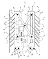
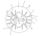
図1〜図4には、本発明による自動走行ロボットの一実施の形態が示されていて、図1は走行前の状態を示す概略縦断面図、図2は図1の下面図、図3は走行開始時及び走行中の状態を示す概略縦断面図、図4は図3の下面図である。
Hereinafter, embodiments of the present invention will be described with reference to the drawings.
1 to 4 show an embodiment of an automatic traveling robot according to the present invention. FIG. 1 is a schematic longitudinal sectional view showing a state before traveling, FIG. 2 is a bottom view of FIG. Fig. 4 is a schematic longitudinal sectional view showing a state at the start of traveling and during traveling, and Fig. 4 is a bottom view of Fig. 3.
すなわち、本実施の形態に示す自動走行ロボット1は、対向配置される一対の脚部2、2と、各脚部2にそれぞれ設けられる複数の毛状体5と、両脚部2、2間に設けられて両脚部2、2を互いに接近、離隔する方向に駆動させる駆動手段6と、両脚部2、2間に設けられて両脚部2、2を振動させる加振手段20とを備えている。
That is, the automatic traveling
各脚部2は、同一長さ、大きさの略半円筒状をなすものであって、耐水性を有する各種の合成樹脂材、金属材等から形成される。両脚部2、2は、周方向の両端面2c、2dが互いに対向するように対向配置され、後述する駆動手段6により互いに接近、離隔可能に構成されている。
Each
各脚部2の凸状の外面2aには、毛状体の束4が長手方向に所定の間隔ごとに複数段に設けられ、各段には周方向に所定の間隔ごとに複数箇所に毛状体の束4が設けられ、これらの複数の毛状体の束4によって各脚部2の外面2aの全体に亘って複数の毛状体5からなる毛状体群3が構成され、この毛状体群3によって自動走行ロボット1を走行させるための推進力が得られる。
On the convex
各毛状体の束4は、同一長さ、径の複数の毛状体5を末広状をなすように束ねて構成したものであって、各脚部2の外面2aに対して全体が所定の角度(本実施の形態においては約40度)で傾斜するように、かつ各脚部2の外面2aから外方に所定の長さ突出するように、各脚部2の外面2aに一束ごとに一体に設けられている。
Each
各毛状体の束4は、各脚部2の外面2aに所定の深さ、径、傾きの孔(図示せず)を穿設し、この孔内に各毛状体の束4の根元部を挿入して接着剤等を充填して硬化させることにより、各脚部2の外面2aに一体に設けられる。本実施の形態においては、各毛状体の束4を3本の毛状体5を束ねて構成しているが、2本又は4本以上の毛状体5を束ねて毛状体の束4を構成してもよい。
Each
各毛状体の束4を構成する各毛状体5は、弾性及び耐水性を有する素材からなる棒状をなすものであって、各毛状体5の素材としては、例えば、ポリエチレン、アクリル系樹脂、塩化ビニル系樹脂等の各種の合成樹脂材、各種の金属材等が挙げられる。但し、これらに限定することなく、同様の特性を有する素材であれば使用することができる。
Each
毛状体群3を構成する各毛状体5は、先端部を管路30の内壁面31に当接させた状態で後述する加振手段20により脚部2に振動を付加することにより、その振動に追従して管路30の長手方向に撓むように弾性変形し、この毛状体5の弾性変形が自動走行ロボット1を走行させる推進力として作用する。
Each of the
駆動手段6は、一対の脚部2、2間に設けられて両脚部2、2間を連結する伸縮自在な連結機構7と、連結機構7を伸縮させるスライダ機構11と、スライダ機構11を駆動させる駆動機構14とを備え、この駆動機構14とスライダ機構11と連結機構7との協働により、両脚部2、2が互いに接近、離隔する方向に駆動する。
The drive means 6 is provided between the pair of
スライダ機構11は、各脚部2の凹状の内面2b側の中央部に、各脚部2の長手方向に沿うように設けられるとともに、両端部が各脚部2の内面2b側に固定部材(図示せず)を介して固定される棒状のスライド軸12と、各スライド軸12にそれぞれスライド自在に設けられる筒状のスライダ13とから構成されている。この場合、スライド軸12は、各脚部2の内面2bの略全長に行き渡るように長さが設定されている。
The
連結機構7は、一対の板状又は棒状の連結部材8、9を中央部間でピン10により結合して構成したものであって、一方の連結部材8の一端部が一方の脚部2のスライド軸12の一端部にピン10により結合され、他端部が他方の脚部2のスライダ13にピン10により結合され、他方の連結部材9の一端部が他方の脚部2のスライド軸12の一端部にピン10により結合され、他端部が一方の脚部2のスライダ13にピン10により結合されている。
The connecting mechanism 7 is configured by connecting a pair of plate-like or rod-like connecting
連結機構7の両連結部材8、9を中央部のピン10を中心として相対的に回動させることにより、両連結部材8、9が両脚部2、2の長手方向と直交する方向に伸縮する。この場合、両連結部材8、9は、最大に伸びることにより図3及び図4に示す状態となり、最小に縮むことにより図1及び図2に示す状態となる。両連結部材8、9の伸縮量は、後述する加振手段20の連結部材23、24の長さ、取り付け位置等を調整することにより、調整することができる。
By rotating the connecting
駆動機構14は、一方の脚部2の内面2b側に出力軸16が図中下方を向くように取り付けられる駆動モータ15と、駆動モータ15の出力軸16の回転を直線運動に変換して、一方の脚部2のスライド軸12上のスライダ13に伝達させる変換機構17とから構成されている。
The
変換機構17は、例えば、駆動モータ15の出力軸16に軸線を一致させた状態で取り付けられるねじ軸18と、ねじ軸18に進退可能に螺着される可動ねじ19とによって構成され、可動ねじ19の一部が一方の脚部2のスライダ13に連結されている。
The
駆動機構14の駆動モータ15を回転駆動させることにより、出力軸16と一体にねじ軸18が回転し、このねじ軸18の回転が可動ねじ19に伝達され、可動ねじ19がねじ軸18上を進退し、可動ねじ19の進退に追従してスライダ13がスライド軸12をスライドし、このスライダ13の変位に追従して連結機構7の両連結部材8、9が伸縮し、両連結部材8、9に追従して他方の脚部2のスライダ13がスライド軸12上をスライドする。そして、このように、両脚部2、2の両スライダ13、13が両連結部材8、9を介して両スライド軸12、12上をスライドすることにより、両脚部2、2が接近、離隔する方向に駆動し、図1及び図2、図3及び図4に示すように、最大に接近した位置と最大に離隔した位置との間を駆動することになる。
By rotating the
加振手段20は、駆動モータ21と、駆動モータ21の出力軸(図示せず)に重心が偏心した状態で取り付けられる錘体(図示せず)と、駆動モータ21を両脚部2、2に連結する連結機構22とを備えており、駆動モータ21を駆動させて、出力軸を回転駆動させることにより、出力軸の回転に追従して錘体が偏心回転し、この錘体の偏心回転が連結機構22を介して両脚部2、2に伝達される。
The vibration means 20 includes a
連結機構22は、一端部が一方の脚部2の図中下端部にピン25により結合されるとともに、他端部が駆動モータ21の図中左端部にピン25により結合される一方の連結部材23と、一端部が一方の脚部2の図中下端部にピン25により結合されるとともに、他端部が駆動モータ21の図中右端部にピン25により結合される他方の連結部材24とから構成され、両脚部2、2が最大に離隔したときには両連結部材23、24は水平状態となり、両脚部2、2が最大に接近したときには両連結部材23、24は垂直状態となる。連結機構22の両連結部材23、24の長さ、ピン25による結合位置等を調整することにより、両脚部2、2が最大に離隔したときの両脚部2、2間の間隔、及び最大に接近したときの両脚部2、2間の間隔を調整することができる。
The
次に、上記のように構成した本実施の形態による自動走行ロボット1の作用について説明する。
まず、図1及び図2に示すように、駆動手段6の駆動機構14の駆動モータ15を駆動させて、スライダ機構11及び連結機構7を介して両脚部2、2を最大に接近させ、この状態を保って点検、探査、清掃等の対象となる管路30内に自動走行ロボット1を装着する。
Next, the operation of the
First, as shown in FIGS. 1 and 2, the
そして、図3及び図4に示すように、駆動手段6の駆動機構14の駆動モータ15を駆動させて、スライダ機構11及び連結機構7を介して両脚部2、2を最大に離隔させ、両脚部2、2の外面2a側の毛状体群3の各毛状体5を管路30の内壁面31に圧接する。
Then, as shown in FIGS. 3 and 4, the
そして、図3及び図4に示すように、加振手段20の駆動モータ21を駆動させて、錘体を偏心回転させることにより振動を発生させ、この振動を連結機構22を介して両脚部2、2に伝達し、両脚部2、2の外面2a側の毛状体群3に伝達し、各毛状体5を管路30の長手方向に撓むように弾性変形させる。
Then, as shown in FIGS. 3 and 4, the
そして、このように両脚部2,2の毛状体群3の各毛状体5を管路30の内壁面31に圧接した状態で弾性変形させることにより、この毛状体群3の各毛状体5の弾性変形が自動走行ロボット1を走行させる推進力として作用し、この推進力によって自動走行ロボット1が管路30内を内壁面31に沿って管路30の長手方向に走行することになる。
And each hair of this
上記のように構成した本実施の形態による自動走行ロボット1にあっては、一対の脚部2、2を駆動手段6によって互いに離隔させることにより、両脚部2、2の外面2a側の毛状体群3の各毛状体5の先端部を管路30の内壁面31に強く圧接させて、この状態で加振手段20により両脚部2、2に振動を付加することにより、毛状体群3の各毛状体5を弾性変形させるように構成したので、管路30の内壁面31の形状、管路30の傾斜角度に影響されずに、充分な推進力が得られることになる。
In the
従って、管路30の内壁面31の形状に影響されることなく、また管路30の傾斜角度に影響されることなく、安定した円滑な走行をすることができるので、各種の内壁面31の形状の管路30、各種の傾斜角度の管路30の点検、探査、清掃等に適用することができる。
Therefore, stable and smooth running can be performed without being influenced by the shape of the
また、脚部2、駆動手段6、及び加振手段20は、簡単な構造を有しているので、それらの製作に要する手間、時間、及び費用を削減することができ、装置全体としての価格を安く抑えることができ、安価なものを提供することができる。
Moreover, since the
なお、前記の説明においては、一対の脚部2、2を対向配置して、両脚部2、2を接近、離隔可能に構成したが、一対以上の脚部2を対向配置して、それらを接近、離隔可能に構成してもよい。
In the above description, the pair of
1 自動走行ロボット
2 脚部 2a 外面
2b 内面 2c、2d 周方向の端面
3 毛状体群 4 毛状体の束
5 毛状体 6 駆動手段
7 連結機構 8 一方の連結部材
9 他方の連結部材 10 ピン
11 スライダ機構 12 スライド軸
13 スライダ 14 駆動機構
15 駆動モータ 16 出力軸
17 変換機構 18 ねじ軸
19 可動ねじ 20 加振手段
21 駆動モータ 22 連結機構
23 一方の連結部材 24 他方の連結部材
25 ピン 30 管路
31 内壁面
DESCRIPTION OF
Claims (5)
各脚部の外面に外方を向くように、かつ外面に対して所定の角度で傾斜するように配置される複数の毛状体と、
前記少なくとも一対の脚部間に設けられて、該脚部を互いに接近、離隔する方向に駆動させる駆動手段と、
各脚部を振動させる加振手段と、を備えてなることを特徴とする自動走行ロボット。 At least a pair of legs disposed opposite to each other;
A plurality of ciliary bodies arranged so as to face outward on the outer surface of each leg and to be inclined at a predetermined angle with respect to the outer surface;
Drive means provided between the at least one pair of legs, and driving the legs in a direction to approach and separate from each other;
An automatic traveling robot comprising vibration means for vibrating each leg.
前記連結機構は、対向配置される一方の脚部のスライド軸に一端部がピン結合され、他端部が対向配置される他方の脚部のスライダにピン結合される一方の連結部材と、該一方の連結部材にピン結合されるとともに、対向配置される一方の脚部のスライダに一端部がピン結合され、他端部が対向配置される他方の脚部のスライド軸にピン結合される他方の連結部材とからなり、
前記駆動機構は、駆動モータと、該駆動モータの駆動力を直線運動に変換して何れかの脚部のスライダに伝達させる変換機構とからなることを特徴とする請求項2に記載の自動走行ロボット。 The slider mechanism includes a slide shaft provided on each leg, and a slider provided slidably on each slide shaft,
The coupling mechanism includes one coupling member, one end of which is pin-coupled to a slide shaft of one leg portion opposed to the other, and a pin which is pin-coupled to a slider of the other leg portion opposed to the other. The other is pin-coupled to one connecting member, one end is pin-coupled to the slider of one leg portion arranged oppositely, and the other end is pin-coupled to the slide shaft of the other leg portion arranged oppositely. Consisting of connecting members
3. The automatic travel according to claim 2, wherein the drive mechanism includes a drive motor and a conversion mechanism that converts a drive force of the drive motor into a linear motion and transmits the linear motion to a slider of any leg portion. robot.
5. The at least one pair of leg portions arranged opposite to each other is configured such that an outer shape forms a circular shape when approaching, and an outer shape forms an oval shape when separated from each other. The automatic traveling robot according to any one of the above.
Priority Applications (1)
| Application Number | Priority Date | Filing Date | Title |
|---|---|---|---|
| JP2006080843A JP4794336B2 (en) | 2006-03-23 | 2006-03-23 | Automated traveling robot |
Applications Claiming Priority (1)
| Application Number | Priority Date | Filing Date | Title |
|---|---|---|---|
| JP2006080843A JP4794336B2 (en) | 2006-03-23 | 2006-03-23 | Automated traveling robot |
Publications (2)
| Publication Number | Publication Date |
|---|---|
| JP2007253281A true JP2007253281A (en) | 2007-10-04 |
| JP4794336B2 JP4794336B2 (en) | 2011-10-19 |
Family
ID=38628018
Family Applications (1)
| Application Number | Title | Priority Date | Filing Date |
|---|---|---|---|
| JP2006080843A Active JP4794336B2 (en) | 2006-03-23 | 2006-03-23 | Automated traveling robot |
Country Status (1)
| Country | Link |
|---|---|
| JP (1) | JP4794336B2 (en) |
Cited By (3)
| Publication number | Priority date | Publication date | Assignee | Title |
|---|---|---|---|---|
| EP2626282A3 (en) * | 2011-12-30 | 2018-05-02 | Innovation First, Inc. | Climbing vibration-driven robot |
| CN112720451A (en) * | 2019-10-28 | 2021-04-30 | 深圳市行知行机器人技术有限公司 | Automatic operation robot and control method thereof for automatic operation according to planned path |
| CN116293203A (en) * | 2023-02-24 | 2023-06-23 | 韶关学院 | Pipeline robot |
Families Citing this family (1)
| Publication number | Priority date | Publication date | Assignee | Title |
|---|---|---|---|---|
| KR101975863B1 (en) * | 2017-11-20 | 2019-05-07 | 한국생산기술연구원 | Soft linear actuator |
Citations (3)
| Publication number | Priority date | Publication date | Assignee | Title |
|---|---|---|---|---|
| JPH02286463A (en) * | 1989-04-28 | 1990-11-26 | Sekiyu Sangyo Katsuseika Center | Pipe mobile device |
| JPH03153457A (en) * | 1989-11-09 | 1991-07-01 | Tokyo Gas Co Ltd | Carriage driven inside pipe |
| JP2005238339A (en) * | 2004-02-24 | 2005-09-08 | Chugoku Electric Power Co Inc:The | Automatic traveling robot using hair-like body as propulsion |
-
2006
- 2006-03-23 JP JP2006080843A patent/JP4794336B2/en active Active
Patent Citations (3)
| Publication number | Priority date | Publication date | Assignee | Title |
|---|---|---|---|---|
| JPH02286463A (en) * | 1989-04-28 | 1990-11-26 | Sekiyu Sangyo Katsuseika Center | Pipe mobile device |
| JPH03153457A (en) * | 1989-11-09 | 1991-07-01 | Tokyo Gas Co Ltd | Carriage driven inside pipe |
| JP2005238339A (en) * | 2004-02-24 | 2005-09-08 | Chugoku Electric Power Co Inc:The | Automatic traveling robot using hair-like body as propulsion |
Cited By (4)
| Publication number | Priority date | Publication date | Assignee | Title |
|---|---|---|---|---|
| EP2626282A3 (en) * | 2011-12-30 | 2018-05-02 | Innovation First, Inc. | Climbing vibration-driven robot |
| CN112720451A (en) * | 2019-10-28 | 2021-04-30 | 深圳市行知行机器人技术有限公司 | Automatic operation robot and control method thereof for automatic operation according to planned path |
| CN116293203A (en) * | 2023-02-24 | 2023-06-23 | 韶关学院 | Pipeline robot |
| CN116293203B (en) * | 2023-02-24 | 2024-02-23 | 韶关学院 | Pipeline robot |
Also Published As
| Publication number | Publication date |
|---|---|
| JP4794336B2 (en) | 2011-10-19 |
Similar Documents
| Publication | Publication Date | Title |
|---|---|---|
| Suzumori et al. | A miniature inspection robot negotiating pipes of widely varying diameter | |
| JP4794336B2 (en) | Automated traveling robot | |
| CN101531217A (en) | Spirally driven walking robot in pipe | |
| JP2008022952A (en) | Advancing device in duct | |
| CN107186707B (en) | Mechanical structure of flexible arm | |
| RU2012143381A (en) | ULTRASONIC TOOL FOR DEFORMATION PROCESSING OF SURFACES AND WELDED COMPOUNDS | |
| JP2018017396A (en) | Actuator main body, control method therefor and holding hand using actuator main body | |
| JP2019155491A (en) | Flexible rope-like driving device | |
| CN102734594B (en) | Pipeline robot | |
| JP4208244B2 (en) | Automatic running robot with hairy body as propulsion means | |
| JP5822905B2 (en) | In-pipe inspection device | |
| Tsukagoshi et al. | Smooth creeping actuator by tip growth movement aiming for search and rescue operation | |
| CN201209606Y (en) | Expanding device of telescoping rod | |
| Onda et al. | Pneumatic driven hollow variable stiffness mechanism aiming non-contact insertion of telescopic guide tubes | |
| US4620474A (en) | Drive mechanism for transmitting force and motion along a path | |
| JP5498068B2 (en) | In-pipe moving device | |
| Becker et al. | Spy bristle bot—A vibration-driven robot for the inspection of pipelines | |
| Watanabe et al. | Bundled rotary helix drive mechanism capable of smooth peristaltic movement | |
| Fukunaga et al. | Cylindrical elastic crawler mechanism for pipe inspection inspired by amoeba locomotion | |
| Quispe et al. | Geometry optimization of helical swimming at low Reynolds number | |
| JP2005238345A (en) | Automatic traveling robot in pipe | |
| CN210319432U (en) | Walking device | |
| Wakana et al. | Development of flexible pneumatic actuator for active scope camera | |
| JPWO2010109534A1 (en) | Moving device, method for manufacturing annular ring rotating part | |
| CN205479978U (en) | Based on pneumatic tendon pneumatic pipe robot system |
Legal Events
| Date | Code | Title | Description |
|---|---|---|---|
| A621 | Written request for application examination |
Free format text: JAPANESE INTERMEDIATE CODE: A621 Effective date: 20090323 |
|
| A977 | Report on retrieval |
Free format text: JAPANESE INTERMEDIATE CODE: A971007 Effective date: 20101125 |
|
| A131 | Notification of reasons for refusal |
Free format text: JAPANESE INTERMEDIATE CODE: A131 Effective date: 20101130 |
|
| A521 | Request for written amendment filed |
Free format text: JAPANESE INTERMEDIATE CODE: A523 Effective date: 20110120 |
|
| TRDD | Decision of grant or rejection written | ||
| A01 | Written decision to grant a patent or to grant a registration (utility model) |
Free format text: JAPANESE INTERMEDIATE CODE: A01 Effective date: 20110719 |
|
| A01 | Written decision to grant a patent or to grant a registration (utility model) |
Free format text: JAPANESE INTERMEDIATE CODE: A01 |
|
| A61 | First payment of annual fees (during grant procedure) |
Free format text: JAPANESE INTERMEDIATE CODE: A61 Effective date: 20110726 |
|
| R150 | Certificate of patent or registration of utility model |
Ref document number: 4794336 Country of ref document: JP Free format text: JAPANESE INTERMEDIATE CODE: R150 Free format text: JAPANESE INTERMEDIATE CODE: R150 |
|
| FPAY | Renewal fee payment (event date is renewal date of database) |
Free format text: PAYMENT UNTIL: 20140805 Year of fee payment: 3 |
|
| FPAY | Renewal fee payment (event date is renewal date of database) |
Free format text: PAYMENT UNTIL: 20140805 Year of fee payment: 3 |
|
| R250 | Receipt of annual fees |
Free format text: JAPANESE INTERMEDIATE CODE: R250 |
|
| R250 | Receipt of annual fees |
Free format text: JAPANESE INTERMEDIATE CODE: R250 |
|
| R250 | Receipt of annual fees |
Free format text: JAPANESE INTERMEDIATE CODE: R250 |
|
| R250 | Receipt of annual fees |
Free format text: JAPANESE INTERMEDIATE CODE: R250 |
|
| R250 | Receipt of annual fees |
Free format text: JAPANESE INTERMEDIATE CODE: R250 |
|
| R250 | Receipt of annual fees |
Free format text: JAPANESE INTERMEDIATE CODE: R250 |