JP2007249109A - Method for adjusting developing device - Google Patents
Method for adjusting developing device Download PDFInfo
- Publication number
- JP2007249109A JP2007249109A JP2006076039A JP2006076039A JP2007249109A JP 2007249109 A JP2007249109 A JP 2007249109A JP 2006076039 A JP2006076039 A JP 2006076039A JP 2006076039 A JP2006076039 A JP 2006076039A JP 2007249109 A JP2007249109 A JP 2007249109A
- Authority
- JP
- Japan
- Prior art keywords
- toner
- roll
- bias voltage
- developing
- adjusting
- Prior art date
- Legal status (The legal status is an assumption and is not a legal conclusion. Google has not performed a legal analysis and makes no representation as to the accuracy of the status listed.)
- Pending
Links
Images


Abstract
Description
本発明は、現像槽に充填されたキャリアとトナーからなる二成分現像剤をブラシ状に保持する磁気ロールと、前記磁気ロールから搬送されたトナーを保持して像担持体に形成された静電潜像を現像する現像ロールを備え、前記磁気ロールと前記現像ロールの夫々に印加するバイアス電圧を調整することにより前記磁気ロールから前記現像ロールへのトナーの搬送量を調整するバイアス電圧調整ステップを備えた現像装置の調整方法に関する。 The present invention relates to a magnetic roll for holding a two-component developer composed of a carrier and toner filled in a developing tank in a brush shape, and an electrostatic formed on an image carrier holding the toner conveyed from the magnetic roll. A bias voltage adjusting step of adjusting a toner conveyance amount from the magnetic roll to the developing roll by adjusting a bias voltage applied to each of the magnetic roll and the developing roll, the developing roll including a developing roll for developing a latent image; The present invention relates to a method of adjusting a developing device provided.
電子写真方式の画像形成装置に組み込まれる現像装置として、特許文献1には、現像装置を複雑にすることなく、長期にわたって現像ローラ上のトナー層厚を常に安定させ、濃度変化のない安定した画像を維持することを目的として、像担持体上に、現像ロールに現像バイアスを印加し始めてから2周目に形成されたトナー層を用いたベタパターンと、次の1回転の間に形成されたトナー層を用いたハーフトーンパターンとを配したトナー層厚検知用パターンを顕像化させ、像担持体上のトナー層厚検知用パターン、または転写体に転写されたトナー層厚検知用パターンのトナー濃度を濃度センサにより検出し、検出したトナー濃度に基づいて磁気ロールと現像ロール間のバイアス電圧の差電圧、つまり、搬送バイアス電圧を制御する現像方法が提案されていた。
As a developing device incorporated in an electrophotographic image forming apparatus,
しかし、上述した従来技術は、現像槽に充填されたトナーの帯電量が理想的な帯電量の範囲に制御されているという条件の下で調整されるものであり、トナーの帯電量が変動すると、適正に調整できないという問題があった。 However, the above-described prior art is adjusted under the condition that the charge amount of the toner filled in the developing tank is controlled within an ideal charge amount range, and the toner charge amount varies. There was a problem that it could not be adjusted properly.
例えば、ハーフトーンパターンの濃度を検知し、その検知結果に基づいて搬送バイアス電圧を設定しているが、トナーの帯電量によっては、調整される搬送バイアス値が高くなり過ぎ、現像ロールと磁気ロール間でリークが起こり、黒点等の画像不具合を起こすことがあった。また、現像ロールと磁気ロールの間隔が狭くなりトナーの搬送障害が起こり、トナー飛散や剤漏れが発生する虞があった。逆に搬送バイアス電圧が低くなりすぎると、現像ロールでのトナー消費量にトナー供給量が追いつかず前の現像履歴が次の現像に影響を与える現像ゴーストが発生する虞があった。 For example, the density of the halftone pattern is detected, and the transport bias voltage is set based on the detection result. However, depending on the charge amount of the toner, the transport bias value to be adjusted becomes too high, and the developing roll and the magnetic roll Leaks occurred between the images, causing image defects such as black spots. In addition, the distance between the developing roll and the magnetic roll is narrowed, and there is a possibility that toner conveyance trouble occurs and toner scattering or agent leakage occurs. Conversely, if the transport bias voltage becomes too low, the toner supply amount cannot catch up with the toner consumption amount on the developing roll, and there is a possibility that a development ghost in which the previous development history affects the next development may occur.
本発明は、上述の従来欠点に鑑み、現像ロールへ搬送するトナー量を適正に調整して安定した画像品位を維持できる現像装置の調整方法を提供する点にある。 SUMMARY OF THE INVENTION In view of the above-described conventional drawbacks, the present invention is to provide a developing device adjustment method capable of maintaining a stable image quality by appropriately adjusting the amount of toner conveyed to a developing roll.
上述の目的を達成するため、本発明による現像装置の調整方法の第一の特徴構成は、特許請求の範囲の書類の請求項1に記載した通り、現像槽に充填されたキャリアとトナーからなる二成分現像剤をブラシ状に保持する磁気ロールと、前記磁気ロールから搬送されたトナーを保持して像担持体に形成された静電潜像を現像する現像ロールを備え、前記磁気ロールと前記現像ロールの夫々に印加するバイアス電圧を調整することにより前記磁気ロールから前記現像ロールへのトナーの搬送量を調整するバイアス電圧調整ステップを備えた現像装置の調整方法であって、前記磁気ロールと前記現像ロールの回転速度差を調整することによりトナーの搬送量を調整する回転数調整ステップを備えている点にある。
In order to achieve the above-mentioned object, the first characteristic configuration of the developing device adjustment method according to the present invention comprises a carrier and a toner filled in a developing tank, as described in
前記二成分現像剤に含まれるトナーの帯電量が適切でないとき等に、磁気ロールと現像ロールの夫々に印加するバイアス電圧による調整では前記磁気ロールから前記現像ロールへのトナーの搬送量を十分に調整しきれないことがあるが、上述の構成によれば、前記磁気ロールと前記現像ロールの回転速度差を調整することにより前記トナーの搬送量を確実に調整することができる。 When the charge amount of the toner contained in the two-component developer is not appropriate, for example, the amount of toner transported from the magnetic roll to the developing roll is sufficiently adjusted by adjusting the bias voltage applied to each of the magnetic roll and the developing roll. Although it may not be able to be adjusted, according to the configuration described above, the toner conveyance amount can be reliably adjusted by adjusting the difference in rotational speed between the magnetic roll and the developing roll.
同第二の特徴構成は、同請求項2に記載した通り、上述の第一特徴構成に加えて、前記バイアス電圧調整ステップによりトナーの搬送量が所定の搬送量に調整できないときに前記回転数調整ステップが実行される点にある。 According to the second characteristic configuration, as described in the second aspect, in addition to the first characteristic configuration described above, when the toner conveyance amount cannot be adjusted to a predetermined conveyance amount by the bias voltage adjustment step, the rotation speed is set. The adjustment step is performed.
トナー飛散や、黒点または白点、現像ゴーストの発生防止による画像品位の維持、さらに省エネや部材の耐久等の経済性から、高すぎる、または低すぎるバイアス電圧を印加することは好ましくなく、実験などを通して求められる好ましい出力範囲で前記バイアス電圧を印加することが望ましいが、前記好ましい出力範囲では前記トナーの搬送量を所定の搬送量に調整できないことがある。上述の構成によれば、前記好ましい出力範囲で前記バイアス電圧を調整してトナーの搬送量を所定の搬送量とすることができる。 It is not desirable to apply a bias voltage that is too high or too low to maintain image quality by preventing the occurrence of toner scattering, black or white spots, development ghosts, and economics such as energy saving and durability of materials. Although it is desirable to apply the bias voltage within a preferable output range obtained through the above-described case, the toner transport amount may not be adjusted to a predetermined transport amount within the preferable output range. According to the above-described configuration, it is possible to adjust the bias voltage within the preferable output range to set the toner conveyance amount to a predetermined conveyance amount.
同第三の特徴構成は、同請求項3に記載した通り、上述の第一または第二特徴構成に加えて、前記バイアス電圧調整ステップは、少なくとも前記現像ロールに所定の低圧バイアス電圧を印加した状態で前記像担持体に形成されるベタパターンまたは転写体への転写後のベタパターンの濃度が所定濃度となるように前記磁気ロールへ印加するバイアス電圧を調整する点にある。 In the third feature configuration, in addition to the first or second feature configuration described above, the bias voltage adjustment step applies at least a predetermined low-voltage bias voltage to the developing roll. The bias voltage applied to the magnetic roll is adjusted so that the density of the solid pattern formed on the image carrier in the state or the density of the solid pattern after transfer to the transfer body becomes a predetermined density.
前記現像ロールに所定の低圧バイアス電圧を印加した状態、つまり、現像効率が低い状態で、ベタパターンが所定濃度となるように、前記磁気ロールへ印加するバイアス電圧を調整、つまり、前記現像ロールと前記磁気ロールの双方に印加されるバイアス電圧の差電圧である搬送バイアス電圧を調整するために、過剰なトナーが現像ロールに搬送されるような条件を排除して現像ロールに形成されるトナーの層厚を適正に調整することができるようになる。 In a state where a predetermined low-voltage bias voltage is applied to the developing roll, that is, in a state where development efficiency is low, the bias voltage applied to the magnetic roll is adjusted so that the solid pattern has a predetermined density, that is, the developing roll In order to adjust the transport bias voltage, which is the difference voltage between the bias voltages applied to both of the magnetic rolls, the condition that the excessive toner is transported to the developing roll is eliminated, and the toner formed on the developing roll is removed. The layer thickness can be adjusted appropriately.
以上説明した通り、本発明によれば、現像ロールへ搬送するトナー量を適正に調整して安定した画像品位を維持できる現像装置の調整方法を提供することができるようになった。 As described above, according to the present invention, it is possible to provide a method of adjusting a developing device that can appropriately adjust the amount of toner conveyed to the developing roll and maintain stable image quality.
以下に本発明による現像装置の調整方法を説明する。本発明による現像装置を備えた電子写真方式の画像形成装置の一例であるプリンタは、図2に示すように、外部機器から入力されたプリントジョブに基づいてMCYKの各色成分のトナー像を形成する画像形成部1と、記録媒体としての用紙を供給・搬送・排紙する用紙トレイや搬送ローラなどからなる給紙部2と、三本のローラ30に支持された無端状の転写体31と、前記転写体31に接触配置された複数の転写ローラ32、33等を備えて構成された転写部3と、トナー像が転写された記録媒体を定着処理する定着部4と、前記外部機器とのデータ送受信を行うインターフェース部5、該プリンタを統括制御するマイクロコンピュータを備えたシステム制御部6を備えて構成される。
The developing device adjustment method according to the present invention will be described below. A printer as an example of an electrophotographic image forming apparatus including a developing device according to the present invention forms a toner image of each color component of MCYK based on a print job input from an external device as shown in FIG. An
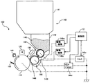
前記画像形成部1は、前記転写体31の周方向に沿って配置されたM(マゼンダ)、C(シアン)、Y(イエロー)、K(ブラック)の各色に対応した4つの感光体ユニット100と、形成するトナー像の濃度が所定の濃度に維持されるように前記転写体31に担持された各色のトナーパターンからの反射光量に基づいて各色の濃度を検出するトナー濃度センサ11と、該画像形成部1を制御する制御部12で構成され、各感光体ユニット100は、図1に示すように、像担持体110と、前記像担持体110の周方向に沿って帯電チャージャー120、露光ヘッド130、現像装置140、クリーナ150、除電ランプ160等が配置されて構成されている。
The
前記像担持体110は、アルミニウム製シリンダの表面に正帯電性光導電体であるアモルファスシリコン層が蒸着された感光体を有する感光体ドラムからなり、前記帯電チャージャー120により正帯電され、前記露光ヘッド130からの露光により露光部分の電荷はシリンダを経てアースされる構成となっている。
The
前記トナー濃度センサ11は、前記転写体31の周方向に沿って配置された前記感光体ユニット100の下流側に配置されている。前記トナー濃度センサ11について詳述すると、前記トナー濃度センサ11は、図3に示すように、前記転写体31の法線方向に対して所定の傾斜角度で単一の偏光光を投光する投光部13と、前記法線方向に対して前記投光部13と反対側に配置され、前記転写体31からの反射光を前記投光光と同一の第1の偏光光と前記投光光と異なる第2の偏光光とに分離する偏光分離部14と、前記第1及び前記第2の偏光光を受光する第1及び第2の受光部15とを備えて構成され、前記第1及び前記第2の偏光光の光量差からトナー濃度を検出する。
The
M(マゼンダ)、C(シアン)、Y(イエロー)、K(ブラック)の各色の前記感光体ユニット100に夫々備えられた前記現像装置140は、図1に示すように、夫々に対応した色のトナーを充填したトナーカートリッジ141と、前記トナーカートリッジ141から供給されるトナーとキャリアを撹拌する現像槽142と、前記現像槽142に充填されたキャリアとトナーからなる二成分現像剤145がブラシ状になった磁気ブラシ143lを保持する磁気ロール143と、前記磁気ロール143から搬送されたトナーをトナー薄層144lとして保持して前記像担持体110に形成された静電潜像を現像する現像ロール144を備えて構成されている。
As shown in FIG. 1, the developing
前記磁気ロール143は、N極とS極を交互に着磁した固定マグネットローラを内包する回転スリーブで構成され、その回転軸にDCバイアス電圧(以下、「バイアス電圧」と言う)Vdc3を印加する高圧回路143vが接続され、さらに、前記磁気ロール143が所定の回転数で一方向に回転するように、前記回転軸はモータと減速機構からなる駆動機構146mに接続され、前記制御部12によりその回転速度が制御可能に構成されている。
The
前記現像ロール144は、均一な帯電性のアルミニウムで構成され、その回転軸にACバイアス電圧Vac4、バイアス電圧Vdc4を印加する高圧回路144vが接続され、さらに、前記現像ロール144が所定の回転数で一方向に回転するように、前記回転軸はモータと減速機構からなる駆動機構146sに接続され、前記制御部12によりその回転速度が制御可能に構成されている。
The developing
前記制御部12は、前記磁気ロール143と前記現像ロール144の双方に印加するバイアス電圧の差電圧である搬送バイアス電圧ΔVcを調整することにより、前記磁気ロール143から前記現像ロール144へのトナーの搬送量を調整する。
The
前記制御部12は、予め設定された所定の周期、つまり、前記現像装置140の累積稼動時間が所定の時間に、または累積プリント枚数が所定のプリント枚数に達した時点で、キャリブレーション制御を実行するように構成されている。
The
即ち、少なくとも前記現像ロール144に所定の低圧バイアス電圧Vdc4(L)を印加した状態で前記像担持体110に形成されるベタパターンまたは前記転写体31への転写後のベタパターンの濃度が所定濃度となるように前記磁気ロール143へ印加する前記バイアス電圧Vdc3を調整するバイアス電圧調整ステップを実行する。
That is, the density of the solid pattern formed on the
ここで、前記バイアス電圧調整ステップにより前記トナーの搬送量が所定の搬送量に調整できないときに前記磁気ロール144と前記現像ロール143の回転速度差を調整することにより前記トナーの搬送量を調整する回転数調整ステップを実行し、その後、前記バイアス電圧調整ステップを再度実行することで、前記
トナーの搬送量を確実に所定の搬送量に調整する。
Here, when the toner conveyance amount cannot be adjusted to a predetermined conveyance amount by the bias voltage adjusting step, the toner conveyance amount is adjusted by adjusting the difference in rotational speed between the
さらに、前記バイアス電圧調整ステップの実行後、前記像担持体110に形成される所定のハーフトーンパターンまたは前記転写体31への転写後の所定のハーフトーンパターンの濃度が所定濃度となるように前記磁気ロール143と前記現像ロール144の夫々に印加するバイアス電圧の差電圧である前記搬送バイアス電圧ΔVcを一定に維持しながら両バイアス電圧を調整する第二のバイアス電圧調整ステップを実行する。
Further, after the bias voltage adjustment step, the density of a predetermined halftone pattern formed on the
なお、前記バイアス電圧調整ステップは、上述の調整方法に限定するものではなく、前記特許文献1による、前記像担持体110上に、前記現像ローラ144上のトナー層厚を検知するため、前記現像ローラ144の現像バイアスを印加し始めてから2周目に形成されたトナー層を用いたベタパターンと、次の1回転の間に形成されたトナー層を用いたハーフトーンパターンとを配したトナー層厚検知用パターンを顕像化させ、前記像担持体110上のトナー層厚検知用パターン、または前記像担持体110上のトナー層厚検知用パターンを転写された転写体31上のトナー層厚検知用パターンにおけるトナー濃度を前記トナー濃度センサ11により検出し、該検出したトナー濃度によって前記現像ローラ144上のトナー層を所定層厚に制御する調整方法など、他の調整方法を用いるものであっても良い。
Note that the bias voltage adjustment step is not limited to the adjustment method described above, and in order to detect the toner layer thickness on the developing
以下に詳述する。前記制御部12は、前記現像装置140の累積稼動時間が所定の時間に、または累積プリント枚数が所定のプリント枚数に達した時点で、各色の感光体ユニット100毎に、所定の回転数Ns(R)で回転する前記現像ロール144に印加する前記ACバイアス電圧Vac4を変更せずに、前記バイアス電圧Vdc4を最小出力電圧に近い所定の低圧バイアス電圧Vdc4(L)に固定して、所定の回転数Nm(R)で回転する前記磁気ロール143に前記バイアス電圧Vdc3を数パターン印加し、夫々のパターンにおいてベタパターンとなるトナー像を前記像担持体110に形成して前記転写体31に担持させる。
This will be described in detail below. When the cumulative operating time of the developing
前記磁気ロール143から前記現像ロール144へのトナーの搬送量をモニターすべく、前記トナー濃度センサ11により夫々の前記トナー像のトナー濃度値を検知し、前記検知したトナー濃度値が前記制御部12の図示しない記憶部に記憶されたベタパターン形成時の所定のトナー濃度値となる前記バイアス電圧Vdc3(O)を求め、前記トナーの搬送量を調整する。
In order to monitor the amount of toner transported from the
前記像担持体110に形成されるベタパターンまたは転写体31への転写後のベタパターンの濃度が所定濃度となる前記バイアス電圧Vdc3(O)が求められないときには、前記磁気ロール143または前記現像ロール144の回転数を変更する、もしくは前記磁気ロール143の回転数と前記現像ロール144の回転数を共に変更することで、前記磁気ロール143と前記現像ロール144の回転速度差を調整する前記回転数調整ステップを実行し、その後、改めて前記バイアス電圧調整ステップを実行し、前記トナーの搬送量を調整する。なお、本実施例では、前記磁気ロール143の回転数のみを変更するものとする。
When the bias voltage Vdc3 (O) at which the density of the solid pattern formed on the
さらに詳述すると、まず、前記バイアス電圧調整ステップの実行において、前記バイアス電圧Vdc4を最小出力電圧に近い所定のバイアス電圧Vdc4(L)に固定し、前記磁気ロール143に第1から第4までのパターンのバイアス電圧Vdc3を印加することで、前記像担持体110に4パターンのベタパターンのトナー像を形成し、図4に示すように、該トナー像を前記転写体31に担持させ、前記トナー濃度センサ11により前記4パターン夫々の前記トナー像のトナー濃度値を検知する。
More specifically, first, in the execution of the bias voltage adjustment step, the bias voltage Vdc4 is fixed to a predetermined bias voltage Vdc4 (L) close to the minimum output voltage, and the
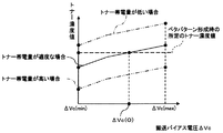
前記バイアス電圧Vdc3と前記バイアス電圧Vdc4(L)の差である前記搬送バイアス電圧ΔVcと前記検知したトナー濃度値より得られる特性曲線から、図5に示すように、前記制御部12の図示しない記憶部に記憶されたベタパターン形成時の所定のトナー濃度値となる最適な搬送バイアス電圧ΔVc(O)を求め、前記最適な搬送バイアス電圧ΔVc(O)と前記バイアス電圧Vdc4(L)より、前記バイアス電圧Vdc3(O)を求め、夫々のバイアス電圧を印加することで前記トナーの搬送量が所定の搬送量となるように調整する。
As shown in FIG. 5, from the characteristic curve obtained from the transport bias voltage ΔVc, which is the difference between the bias voltage Vdc3 and the bias voltage Vdc4 (L), and the detected toner density value, the
ここで、前記現像槽142内の前記二成分現像剤145のトナー帯電量の増加や低下、キャリアコート剥れ等により、前記磁気ロール143から前記現像ロール144へ搬送するトナーの搬送特性が変化して、出力範囲を逸脱する前記バイアス電圧Vdc3を出力しなければ前記最適な搬送バイアス電圧ΔVc(O)を求めることができないときには、前記磁気ロール143の回転数Nm(R)を予め設定した値Nm(O)に変更する前記回転数調整ステップを実行することで前記搬送特性を変化させ、その後、改めて前記バイアス電圧調整ステップを実行して、前記最適な搬送バイアス電圧ΔVc(O)を求め、前記トナーの搬送量を調整する。
Here, the transport characteristics of the toner transported from the
前記回転数調整ステップについて詳述すると、図6に示すように、前記二成分現像剤145のトナー帯電量が低くなると前記トナーの搬送特性は向上するため、最低の搬送バイアス電圧ΔVc(min)でも過剰なトナーが搬送されることとなる。逆に、前記トナー帯電量が高くなると前記トナーの搬送特性は低下するため、最高の搬送バイアス電圧ΔVc(max)でも十分なトナーが搬送されない。そこで、前記制御部12は、前記現像ロール144の回転数Ns(R)は一定のまま、前記バイアス電圧調整ステップを実行したときに得られた前記特性曲線に基づき、前記磁気ロール144の回転数Nm(R)を実験などを通して取得し、予め設定した値Nm(O)に変更し、前記磁気ロール143と前記現像ロール144の回転速度差を前者の場合には低く、後者の場合には高く変更することで前記トナーの搬送特性を変化させ、その後、前記バイアス電圧調整ステップを再度実行し、前記最適な搬送バイアス電圧ΔVc(O)を求め、前記転写体31に転写したベタパターンの濃度が所定濃度となるように調整する。
The rotation speed adjustment step will be described in detail. As shown in FIG. 6, since the toner transport characteristics are improved when the toner charge amount of the two-
さらに、前記像担持体110に形成される所定のハーフトーンパターンまたは前記転写体31への転写後の所定のハーフトーンパターンの濃度が所定濃度となるように前記最適な搬送バイアス電圧ΔVc(O)を維持しながら前記バイアス電圧Vdc3、Vdc4を調整する第二のバイアス電圧調整ステップを実行し、キャリブレーション制御を終了する。
Further, the optimum transport bias voltage ΔVc (O) is set so that the density of a predetermined halftone pattern formed on the
以下、別実施形態を説明する。上述の構成では、前記像担持体110として、アルミニウム製シリンダの表面に正帯電性光導電体であるアモルファスシリコン層が蒸着された感光体を有する感光体ドラムを採用したが、前記感光体が有機光導電体であるOPCドラムや、前記感光体がセレンなどであるその他の種類の光導電性半導体ドラムを採用する構成であっても良く、この場合、前記感光体の帯電特性に応じて、採用する二成分現像剤は適宜変更すれば良い。
Hereinafter, another embodiment will be described. In the configuration described above, a photosensitive drum having a photosensitive body in which an amorphous silicon layer, which is a positively chargeable photoconductor, is deposited on the surface of an aluminum cylinder is used as the
上述の実施例では、前記磁気ロール143と前記現像ロール144の前記回転速度差の調整について、前記制御部12は前記現像ロール143の回転数Nm(R)は一定に保ち、前記磁気ロール144の回転数Nm(R)を実験などを通して予め設定した値Nm(O)に変更する構成としたが、これに限定するものではなく、前記現像ロール144の回転数のみを変更する、もしくは前記磁気ロール143の回転数と前記現像ロール144の回転数を共に変更する構成でもよい。ただし、前記現像ロール144の回転数を変化させるときにおいては、少なくともその回転数を下げる時には、前記像担持体110等の回転数もこれに合わせて変化させる必要がある。これは、前記現像ロール144の回転数が変化すると、前記像担持体110へのトナーの搬送特性が変化するためであり、特に、前記現像ロール144の回転数を下げるときにおいて影響が大きいためである。
In the above-described embodiment, with respect to the adjustment of the rotational speed difference between the
上述の実施例では、トナー濃度値の検知において4パターンのトナー像を形成したが、これに限定するものではなく、機器特性や使用条件、コストなどの諸条件に合わせ最適なパターンのトナー像を形成する構成であっても良く、夫々のパターンのトナー像のトナー濃度値を検知し、前記磁気ロール143及び前記現像ロール144に印加するバイアス電圧Vdc3、Vdc4の調整を行えば良い。
In the above-described embodiment, four patterns of toner images are formed in the detection of the toner density value. However, the present invention is not limited to this, and an optimum pattern of toner images is selected according to various conditions such as device characteristics, use conditions, and costs. A configuration may be adopted in which the toner density values of the toner images of the respective patterns are detected, and the bias voltages Vdc3 and Vdc4 applied to the
上述の構成では、回転数調整ステップは、前記現像ロール144の回転数Ns(R)は一定のまま、バイアス電圧調整ステップを実行したときに得られた前記特性曲線に基づき、前記磁気ロール144の回転数Nm(R)を実験などを通して取得し、予め設定した値Nm(O)に変更し、前記磁気ロール143と前記現像ロール144の回転速度差を前者の場合には低く、後者の場合には高く変更することで前記トナーの搬送特性を変化させる構成としたが、前記搬送バイアス電圧ΔVcが所定の値となるように前記バイアス電圧Vdc3を調整し、該搬送バイアス電圧ΔVcにおいて、所定のトナーの搬送量が得られるように前記回転速度差をリニアに変更する構成としてもよく、この場合、前記回転数調整ステップ実行後に、再度バイアス電圧調整ステップを実行する必要は無い。
In the above-described configuration, the rotation speed adjustment step is performed based on the characteristic curve obtained when the bias voltage adjustment step is executed while the rotation speed Ns (R) of the developing
上述の構成では、回転数調整ステップは、前記現像ロール144の回転数Ns(R)は一定のまま、バイアス電圧調整ステップを実行したときに得られた前記特性曲線に基づき、前記磁気ロール144の回転数Nm(R)を実験などを通して取得し、予め設定した値Nm(O)に変更し、前記磁気ロール143と前記現像ロール144の回転速度差を前者の場合には低く、後者の場合には高く変更することで前記トナーの搬送特性を変化させる構成としたが、前記回転速度差を所定の値に変更した後、所定のトナーの搬送量が得られるように前記バイアス電圧Vdc3を調整する構成としてもよく、この場合、前記回転数調整ステップ実行後に、再度バイアス電圧調整ステップを実行する必要は無い。
In the above-described configuration, the rotation speed adjustment step is performed based on the characteristic curve obtained when the bias voltage adjustment step is executed while the rotation speed Ns (R) of the developing
上述の実施形態は何れも本発明の一実施例に過ぎず、当該記載により本発明の範囲が限定されるものではなく、各部の具体的構成は本発明による作用効果を奏する範囲において適宜変更することができることは言うまでもない。 The above-described embodiments are merely examples of the present invention, and the scope of the present invention is not limited by the description, and the specific configuration of each part is appropriately changed within the scope of the effects of the present invention. It goes without saying that it can be done.
12:制御部
100: 感光体ユニット
140: 現像装置
141: トナーカートリッジ
142: 現像槽
143:磁気ロール
143l:磁気ブラシ
143v:高圧回路(磁気ロール用)
144:現像ロール
144l:トナー薄層
144v:高圧回路(現像ロール用)
145:二成分現像剤(トナーとキャリア)
146m:駆動機構(磁気ロール用)
146s:駆動機構(現像ロール用)
12: Control unit 100: Photosensitive unit 140: Developing device 141: Toner cartridge 142: Developing tank 143: Magnetic roll 143l:
144: Developing roll 144l: Toner
145: Two-component developer (toner and carrier)
146m: Drive mechanism (for magnetic roll)
146s: Drive mechanism (for developing roll)
Claims (3)
前記磁気ロールと前記現像ロールの回転速度差を調整することによりトナーの搬送量を調整する回転数調整ステップを備えている現像装置の調整方法。 A magnetic roll that holds a two-component developer consisting of a carrier and toner filled in a developing tank in a brush shape, and an electrostatic latent image formed on an image carrier by holding the toner conveyed from the magnetic roll. And a developing device including a bias voltage adjusting step for adjusting a toner conveyance amount from the magnetic roll to the developing roll by adjusting a bias voltage applied to each of the magnetic roll and the developing roll. Adjustment method,
A developing device adjustment method comprising a rotation speed adjustment step of adjusting a toner conveyance amount by adjusting a rotational speed difference between the magnetic roll and the developing roll.
Priority Applications (1)
| Application Number | Priority Date | Filing Date | Title |
|---|---|---|---|
| JP2006076039A JP2007249109A (en) | 2006-03-20 | 2006-03-20 | Method for adjusting developing device |
Applications Claiming Priority (1)
| Application Number | Priority Date | Filing Date | Title |
|---|---|---|---|
| JP2006076039A JP2007249109A (en) | 2006-03-20 | 2006-03-20 | Method for adjusting developing device |
Publications (1)
| Publication Number | Publication Date |
|---|---|
| JP2007249109A true JP2007249109A (en) | 2007-09-27 |
Family
ID=38593429
Family Applications (1)
| Application Number | Title | Priority Date | Filing Date |
|---|---|---|---|
| JP2006076039A Pending JP2007249109A (en) | 2006-03-20 | 2006-03-20 | Method for adjusting developing device |
Country Status (1)
| Country | Link |
|---|---|
| JP (1) | JP2007249109A (en) |
Cited By (1)
| Publication number | Priority date | Publication date | Assignee | Title |
|---|---|---|---|---|
| JP2010286543A (en) * | 2009-06-09 | 2010-12-24 | Konica Minolta Business Technologies Inc | Image forming apparatus and image adjusting method |
Citations (5)
| Publication number | Priority date | Publication date | Assignee | Title |
|---|---|---|---|---|
| JPH09311551A (en) * | 1996-05-23 | 1997-12-02 | Hitachi Ltd | Developing device and color electrophotographic device using the same |
| JP2003015380A (en) * | 2001-07-04 | 2003-01-17 | Kyocera Corp | Method for controlling tandem type image forming device |
| JP2003270902A (en) * | 2002-03-15 | 2003-09-25 | Kyocera Corp | Image forming method for color tandem type image forming apparatus |
| JP2005055841A (en) * | 2003-07-22 | 2005-03-03 | Kyocera Mita Corp | Development method for image forming apparatus |
| JP2005189708A (en) * | 2003-12-26 | 2005-07-14 | Kyocera Mita Corp | Developing device in image forming apparatus |
-
2006
- 2006-03-20 JP JP2006076039A patent/JP2007249109A/en active Pending
Patent Citations (5)
| Publication number | Priority date | Publication date | Assignee | Title |
|---|---|---|---|---|
| JPH09311551A (en) * | 1996-05-23 | 1997-12-02 | Hitachi Ltd | Developing device and color electrophotographic device using the same |
| JP2003015380A (en) * | 2001-07-04 | 2003-01-17 | Kyocera Corp | Method for controlling tandem type image forming device |
| JP2003270902A (en) * | 2002-03-15 | 2003-09-25 | Kyocera Corp | Image forming method for color tandem type image forming apparatus |
| JP2005055841A (en) * | 2003-07-22 | 2005-03-03 | Kyocera Mita Corp | Development method for image forming apparatus |
| JP2005189708A (en) * | 2003-12-26 | 2005-07-14 | Kyocera Mita Corp | Developing device in image forming apparatus |
Cited By (1)
| Publication number | Priority date | Publication date | Assignee | Title |
|---|---|---|---|---|
| JP2010286543A (en) * | 2009-06-09 | 2010-12-24 | Konica Minolta Business Technologies Inc | Image forming apparatus and image adjusting method |
Similar Documents
| Publication | Publication Date | Title |
|---|---|---|
| JP2002162801A (en) | Image forming device | |
| JP4925722B2 (en) | Image forming apparatus | |
| JP4845546B2 (en) | Development device adjustment method | |
| JP2010191364A (en) | Image forming apparatus | |
| US7356273B2 (en) | Image forming apparatus with switched-potential responsive to attenuation of a remaining voltage | |
| JP4502971B2 (en) | Development device adjustment method | |
| US11048192B1 (en) | Image forming apparatus capable of suppressing occurrence of image defects in response to difference in carrier resistance and obtaining high image quality | |
| JP2008046423A (en) | Image forming apparatus | |
| JP2007249109A (en) | Method for adjusting developing device | |
| JP2005189494A (en) | Image forming apparatus | |
| JP5361982B2 (en) | Image forming apparatus | |
| JP2005017631A (en) | Image forming apparatus | |
| JP2005275119A (en) | Image forming apparatus | |
| JP2002162795A (en) | Image forming device | |
| JP5221418B2 (en) | Image forming apparatus | |
| JP2003005490A (en) | Image forming device | |
| JP2007206152A (en) | Bias voltage adjustment method of development device | |
| JP4909022B2 (en) | Image forming apparatus | |
| JP2011191664A (en) | Image forming apparatus | |
| JP2005173075A (en) | Image forming apparatus | |
| JP2005148355A (en) | Image forming apparatus | |
| JP2005148198A (en) | Image forming apparatus | |
| JP2005017627A (en) | Image forming apparatus | |
| JP2004287291A (en) | Image forming apparatus | |
| JP4556529B2 (en) | Toner amount adjusting apparatus and method, toner amount adjusting program |
Legal Events
| Date | Code | Title | Description |
|---|---|---|---|
| A621 | Written request for application examination |
Free format text: JAPANESE INTERMEDIATE CODE: A621 Effective date: 20090227 |
|
| A977 | Report on retrieval |
Free format text: JAPANESE INTERMEDIATE CODE: A971007 Effective date: 20110525 |
|
| A131 | Notification of reasons for refusal |
Free format text: JAPANESE INTERMEDIATE CODE: A131 Effective date: 20110531 |
|
| A02 | Decision of refusal |
Free format text: JAPANESE INTERMEDIATE CODE: A02 Effective date: 20111004 |