JP2007247703A - Bearing and method for bearing shaft of rotor - Google Patents
Bearing and method for bearing shaft of rotor Download PDFInfo
- Publication number
- JP2007247703A JP2007247703A JP2006069184A JP2006069184A JP2007247703A JP 2007247703 A JP2007247703 A JP 2007247703A JP 2006069184 A JP2006069184 A JP 2006069184A JP 2006069184 A JP2006069184 A JP 2006069184A JP 2007247703 A JP2007247703 A JP 2007247703A
- Authority
- JP
- Japan
- Prior art keywords
- ball
- pair
- support
- rotating body
- curved section
- Prior art date
- Legal status (The legal status is an assumption and is not a legal conclusion. Google has not performed a legal analysis and makes no representation as to the accuracy of the status listed.)
- Pending
Links
Images


Landscapes
- Rolling Contact Bearings (AREA)
- Mounting Of Bearings Or Others (AREA)
Abstract
Description
本発明は、回転体を軸受けするためのベアリング及び回転体の軸受け方法に関する。 The present invention relates to a bearing for bearing a rotating body and a bearing method for the rotating body.
一般に、回転体を支持体に対して回転可能に軸受けするための部品として、ベアリングが用いられている。このベアリングは、例えば、図12の側断面図に示すラジアルボールベアリング300のように、シャフト(図示せず)が挿入、固定されるところの内筒部302と、該内筒部302の径方向外側に同軸に配置された外筒部304と、内筒部302の凹部と外筒部304の凹部との間に介在された多数のボール306と、該ボール306を回転可能に覆っている覆い部材308と、を有する。外筒部304と、内筒部302とは、それらの凹部に嵌り込んだボール306を介して低摩擦で連動している。かくして、外筒部304を固定することにより、内筒部302に挿入、固定されたシャフトを自在に回転することができる。また、この構成により、径方向及び軸方向に荷重がかかったときでも、良好な滑動を提供することができる。
Generally, a bearing is used as a part for bearing a rotating body rotatably with respect to a support. The bearing includes, for example, an inner
しかしながら、上記従来技術のベアリング機構では、例えば大きな直径のシャフトの用途に適用するベアリングを製作すると、中実である内筒部302と外筒部304とが共に大型化するため重量が大幅に増大する。また、従来技術のベアリング機構では、構造的に形状を変更する自由度が少ないため、省スペース、多種多様な空間的、構造的配置の軸受け用途に十分に適合することができない、という問題がある。
However, in the above conventional bearing mechanism, for example, when a bearing that is applied to a large-diameter shaft is manufactured, both the solid inner
本発明は、上記事実に鑑みてなされたもので、多種多様な軸受け用途に適合できる、軽量化及び省スペース化を図った、ベアリング及び回転体の軸受け方法を提供することをその目的とする。 The present invention has been made in view of the above-described facts, and an object of the present invention is to provide a bearing and a rotating body bearing method that can be adapted to various types of bearing applications and that achieves weight reduction and space saving.
上記課題を解決するため、本発明の一態様に係るベアリングは、回転体を支持体に対して回転可能に軸受けするため複数のボールを収容する一対の環状の収容部を備えるベアリングであって、該一対の収容部の各々は、環状の平坦区分と、該平坦区分から軸方向に延在してボールを収容するように湾曲された湾曲区分と、を有し、該平坦区分及び該湾曲区分は、複数のボールが周方向に並んで配置される環状溝を形成し、平坦区分のエッジの高さは、収容されたボールの高さよりも高く、湾曲区分のエッジの高さは収容されたボールの高さよりも低く、一対の収容部は、一方の収容部の湾曲区分が他方の収容部の湾曲区分と向き合った状態で、支持体に嵌合され、回転体は、一対の平坦区分の間にボールと当接した状態で配置され、該回転体は、ボール上を滑動することにより支持体に対して回転可能となる。 In order to solve the above-described problem, a bearing according to an aspect of the present invention is a bearing including a pair of annular accommodating portions that accommodate a plurality of balls in order to rotatably support a rotating body with respect to a support, Each of the pair of receiving portions includes an annular flat section, and a curved section that extends in an axial direction from the flat section and is curved to receive the ball. The flat section and the curved section Forms an annular groove in which a plurality of balls are arranged side by side in the circumferential direction, the height of the edge of the flat section is higher than the height of the accommodated ball, and the height of the edge of the curved section is accommodated The pair of accommodating portions is lower than the height of the ball, and the rotating body is fitted with a pair of flat sections with the curved section of one accommodating section facing the curved section of the other accommodating section. Arranged in contact with the ball between the rotating body , It becomes rotatable relative to the support by sliding on balls.
好ましくは、環状溝は、全周に亘って延在し、複数のボールは、環状溝内で周方向に自在に滑動するため隣接するボール間にクリアランスを有して配列されている。好ましくは、一対の収容部は、支持体に圧入される。これにより、本発明のベアリングの組み付けを容易にすると共に、収容部が支持体から脱落することを防止することができる。 Preferably, the annular groove extends over the entire circumference, and the plurality of balls are arranged with a clearance between adjacent balls for sliding freely in the circumferential direction within the annular groove. Preferably, the pair of accommodating portions are press-fitted into the support body. As a result, the assembly of the bearing of the present invention can be facilitated, and the housing portion can be prevented from falling off the support.
ベアリングの回転体に径方向の力が加わったとき、その力は、回転体の周端部、ボール、収容部及び支持体の順に伝達する。径方向の力は、最終的に支持体で受けることができるので、本態様のベアリングは、径方向の荷重に容易に耐えることができる。また、一対の収容部が、一対の湾曲部を対向させた状態で並んで支持体上に配置されているため、周端部が傾いたとしても、安定して回転体を支持することが可能となる。ここで、一対の収容部の各々の湾曲区分が当接しているのが好ましい。これにより、一対の収容部同士が互いを支持し合うので、軸方向のサイズを小さくすると共に、収容部のガタ揺れを防止することができる。また、湾曲区分のエッジは、該湾曲区分に収容されたボールの高さよりも低い位置にあり、これにより、回転体の周端部のボール当接面を、一対の収容部に亘って延在する幅広い平坦部としても、湾曲区分のエッジに当たることなく、安定した状態で回転体をボール上で滑動させることができる。なお、構造を簡単にするため、一対の収容部は、互いに鏡像対称となるように形成、配置されていてもよい。 When a radial force is applied to the rotating body of the bearing, the force is transmitted in the order of the peripheral end of the rotating body, the ball, the housing portion, and the support body. Since the radial force can finally be received by the support, the bearing of this aspect can easily withstand the radial load. In addition, since the pair of storage portions are arranged on the support side by side with the pair of curved portions facing each other, the rotating body can be stably supported even if the peripheral end portion is inclined. It becomes. Here, it is preferable that the curved sections of the pair of accommodating portions are in contact with each other. Thereby, since a pair of accommodating part supports each other, while reducing the size of an axial direction, it can prevent the backlash of an accommodating part. Further, the edge of the curved section is at a position lower than the height of the ball accommodated in the curved section, whereby the ball contact surface of the peripheral end portion of the rotating body extends across the pair of accommodating sections. Even with a wide flat portion, the rotating body can be slid on the ball in a stable state without hitting the edge of the curved section. In order to simplify the structure, the pair of accommodating portions may be formed and arranged so as to be mirror-symmetric with respect to each other.
好ましくは、一対の平坦区分の少なくとも1つは、回転体と、支持体から延在する側壁との間に配置される。これにより、回転体にその軸方向に力が加わったとき、その力は、回転体の周端部から、一対の収容部のうち、加わった力の向きに配置された収容部の平坦区分を介して、対向する側壁へと伝達する。このように、軸方向の力は、最終的に側壁で受けることができるので、本態様のベアリングは、軸方向の荷重にも容易に耐えるように構成することができる。また、平坦区分が挟持されているので、ベアリングを更に強固に支持体に固定することができる。 Preferably, at least one of the pair of flat sections is disposed between the rotating body and the side wall extending from the support. As a result, when a force is applied to the rotating body in the axial direction, the force is divided from the peripheral end portion of the rotating body to the flat section of the housing portion arranged in the direction of the applied force among the pair of housing portions. To the opposite side wall. As described above, since the axial force can be finally received by the side wall, the bearing of this aspect can be configured to easily withstand the axial load. Further, since the flat section is sandwiched, the bearing can be more firmly fixed to the support.
好ましくは、湾曲区分は、該湾曲区分のエッジと平坦区分との間の間隔がボールの直径よりも小さくなるように形成されている。この場合、ボールは、湾曲区分内に圧入されてもよい。これによって、ボールを脱落のおそれなく収容部に確実に収容させることができ、安定した回転運動が可能となる。 Preferably, the curved section is formed such that the distance between the edge of the curved section and the flat section is smaller than the diameter of the ball. In this case, the ball may be pressed into the curved section. As a result, the ball can be reliably accommodated in the accommodating portion without fear of falling off, and a stable rotational motion is possible.
本発明のベアリングは、回転体を支持体の径方向外側に配置する態様、及び、従来技術の欄で説明した通常のラジアルベアリングのように、回転体(シャフトを受け入れる内筒部)を支持体(外筒部)の径方向内側に配置する態様のいずれにも適用可能である。前者の態様では、一対の収容部は、湾曲区分の底部が収容されたボールよりも径方向内側となるように構成され、回転体は中央孔を有し、一対の収容部は、該湾曲区分の底部が支持体の外周壁上に載置された状態で該支持体の径方向外側に嵌合され、回転体は中央孔の内周壁がボールと接触した状態で該ボール上を滑動可能に配置される。後者の態様では、支持体は中央孔を有し、一対の収容部は、湾曲区分の底部が収容されたボールよりも径方向外側となるように構成され、一対の収容部は、該湾曲区分の底部が支持体の中央孔の内周壁上に載置された状態で該支持体の中央孔内に嵌合され、回転体は該回転体の外周壁がボールと接触した状態で該ボール上を滑動可能に配置される。 In the bearing of the present invention, the rotating body (inner cylinder part that receives the shaft) is supported as in the normal radial bearing described in the section of the related art, and the mode in which the rotating body is arranged on the outer side in the radial direction of the supporting body. The present invention can be applied to any of the modes arranged on the radially inner side of the (outer cylinder). In the former aspect, the pair of storage portions are configured to be radially inward of the ball in which the bottom portion of the curved section is stored, the rotating body has a central hole, and the pair of storage portions has the curved section. The bottom part of the support body is fitted on the outer side in the radial direction of the support body in a state where it is placed on the outer peripheral wall of the support body, and the rotating body can slide on the ball with the inner peripheral wall of the central hole in contact with the ball Be placed. In the latter aspect, the support has a central hole, and the pair of storage portions is configured to be radially outward from the ball in which the bottom of the curved section is stored. The bottom part of the rotating body is fitted into the central hole of the support body in a state where it is placed on the inner peripheral wall of the central hole of the support body, and the rotating body is placed on the ball with the outer peripheral wall of the rotating body in contact with the ball. Is slidably arranged.
以上のように、本発明は、平坦区分と湾曲区分とを有する収容部にボールを収容するという簡単な構成で、軸方向及び径方向の荷重に耐えることができるベアリングを提供することができる。本発明の構成では、例えば収容部は、1枚の金属板を加工するだけで作成することができるため、ベアリングの製作をきわめて簡単にすることができ、直径の大きな回転体を用いたとしても大幅な軽量化を達成することができる。 As described above, the present invention can provide a bearing that can withstand axial and radial loads with a simple configuration in which a ball is housed in a housing portion having a flat section and a curved section. In the configuration of the present invention, for example, since the housing portion can be created by processing only one metal plate, the manufacture of the bearing can be extremely simplified, even if a rotating body having a large diameter is used. Significant weight reduction can be achieved.
本発明の更に別の態様は、回転体を支持体に対して回転可能に軸受けする方法に関する。本方法は、複数のボールを収容する一対の収容部であって、一対の収容部の各々は、環状の平坦区分と、該平坦区分から軸方向に延在してボールを収容するように湾曲された環状の湾曲区分と、を有し、該平坦区分及び該湾曲区分は、複数のボールが周方向に並んで配置される環状溝を形成し、平坦区分のエッジの高さは、収容されたボールの高さよりも高く、湾曲区分のエッジの高さは収容されたボールの高さよりも低い、一対の収容部を用意し、一対の収容部のうち一方を、支持体に嵌合し、回転体を、嵌合された収容部に収容されたボールと当接するように載置し、一対の収容部のうち他方の収容部の湾曲区分が一方の収容部の湾曲区分と向き合うように、該他方の収容部を支持体に嵌合し、これによって、回転体は、一対の収容部の平坦区分の間にボールと当接した状態で配置され、該回転体は、ボール上を滑動することにより支持体に対して回転可能となる、各工程を備える、
本態様によれば、様々な態様の回転体を支持体上で回転させる用途に柔軟に対応する軸受け方法を提供することができる。勿論、上記した本発明の態様に係るベアリングの利点を全て享受することができる。また、回転体及び支持体が予め与えられたものである場合、本態様では、それらの一部をベアリング機構の一部として使用するため、軽量化を更に促進することができる。
Yet another aspect of the present invention relates to a method of bearing a rotating body rotatably with respect to a support. The method includes a pair of accommodating portions that accommodate a plurality of balls, each of the pair of accommodating portions being curved so as to accommodate an annular flat section and an axially extending portion from the flat section. An annular curved section, wherein the flat section and the curved section form an annular groove in which a plurality of balls are arranged in a circumferential direction, and the height of the edge of the flat section is accommodated. Preparing a pair of housing portions that are higher than the height of the balls and the height of the edge of the curved section is lower than the height of the housed balls, and fitting one of the pair of housing portions to the support, The rotating body is placed so as to come into contact with the ball accommodated in the fitted accommodating portion, and the curved section of the other accommodating portion of the pair of accommodating portions faces the curved section of the one accommodating portion. The other accommodating portion is fitted to the support body, whereby the rotating body is connected to the pair of accommodating portions. Are arranged in a state in which balls and in contact between the tongue segment, the rotating body is made rotatable relative to the support by sliding on balls, comprising the steps,
According to this aspect, it is possible to provide a bearing method that can flexibly correspond to an application in which a rotating body of various aspects is rotated on a support. Of course, all the advantages of the bearing according to the above-described aspect of the present invention can be enjoyed. Further, in the case where the rotating body and the support are provided in advance, in this embodiment, a part of them is used as a part of the bearing mechanism, so that weight reduction can be further promoted.
本発明の他の目的及び利点は、以下で説明される本発明の好ましい実施形態を参酌することによって、より明瞭に理解されよう。 Other objects and advantages of the present invention will be more clearly understood by referring to the preferred embodiments of the present invention described below.
本発明の第1の実施形態を図1及び図2を用いて説明する。 A first embodiment of the present invention will be described with reference to FIGS.
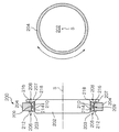
図1に示されるように、本発明の第1の実施形態に係るベアリング200は、リング形状の回転体204をディスク形状の環状の支持体202に対して同じ軸Sの周りに矢印方向に回転可能に軸受けするため、ボール210を収容する一対の環状の収容部206、208を備える。一対の収容部206、208の各々は、環状の平坦区分212、216と、該平坦区分から軸方向に延在してボールを収容するように湾曲された湾曲区分214、218と、を有する。一対の収容部206、208は、一方の収容部206の湾曲区分214が他方の収容部208の湾曲区分218と向き合った状態で、支持体202に嵌合されている。この例では、湾曲区分214と湾曲区分218とが当接し、湾曲区分214、218の底部が支持体202の外周壁203の底平面に接している。
As shown in FIG. 1, the
好ましくは、一対の収容部206、208は、支持体202に圧入される。これにより、一対の収容部206、208を支持体202に確実且つ簡単に取り付けることができる。また、1つの平坦区分216は、回転体204と、支持体から延在する側壁207との間に配置され、収容部の支持体への固定をより確実なものとしている。
Preferably, the pair of
また、収容されたボール210の頂上高さは、湾曲区分214、218のエッジの高さよりも高い。これによって、回転体204の周端部209は、湾曲区分のエッジに当たることなく、ボール210に当接することができる。更に、平坦区分のエッジの高さは、収容されたボールの高さよりも高い。これによって一対の平坦区分212、216の間に回転体204の一部が挟持されるので、該回転体の軸方向の位置ずれを防止し、よって回転体の円滑な回転を確保することができる。
Also, the top height of the contained
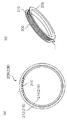
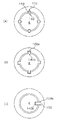
図2(a)には、収容部206又は208を軸方向Sから眺めた正面図が示され、図2(b)には、一対の収容部206、208の斜視図が示されている。図2(a)、(b)に示されるように、該平坦区分及び該湾曲区分は、環状溝211を形成し、該環状溝211は、全周に亘って延在する。図2(a)では、湾曲部214(218)の一部が破断された状態で示されており、環状溝211内に複数のボール210が周方向に並んで配置されていることがわかる。このように全周に亘ってボールが配列されているので、径方向の耐荷重性能を向上させることができる。これらのボール210は、環状溝211内で周方向に自在に滑動するため隣接するボール間にクリアランスを有して配列されるのが好ましい。本実施例では、環状溝211には、個々のボールを定位置に置くための座席が形成されておらず、ボール210は、全周に沿って移動可能であり、これにより、回転体204の滑らかな回転が可能となる。勿論、環状溝211内に個々のボールを定位置で収容するための座席が形成される態様も考えられる。
FIG. 2A shows a front view of the
なお、湾曲区分214、218は、該湾曲区分のエッジと平坦区分212、216との間の間隔がボール210の直径よりも小さくなるように形成され、ボール210は、湾曲区分内に圧入されるのが好ましい。これによって、ボール210を脱落のおそれなく収容部に確実に収容させることができる。図示の例では、一対の収容部206、208は、鏡像対称に形成、配置されているが、用途、使用状況に応じて、非対称に形成、配置することもできる。
The
図3には、本発明の第2の形態に係るベアリング250が示されている。ベアリング250は、回転体を環状の支持体の径方向外側に配置する図1のベアリング200とは対照的に、回転体204aを環状の支持体202aの径方向内側に配置し、一対の収容部206a、208aは、ボール210と回転体204aとの接触部が径方向内向きとなるように配置される。即ち、支持体は中央孔213を有し、一対の収容部206a、208aは、湾曲区分の底部が、収容されたボール210よりも径方向外側となるように構成される。よって、一対の収容部部206a、208aは、該湾曲区分の底部が支持体の中央孔213の内周壁215上に載置された状態で該支持体の中央孔213内に嵌合される。その他の構成については、図1及び図2に示された構成から当業者には明らかである。
FIG. 3 shows a
次に、本発明の第1及び第2の実施形態の作用を説明する。 Next, the operation of the first and second embodiments of the present invention will be described.
ベアリング200(250)の回転体204に径方向の力が加わったとき、その力は、回転体204の周端部209、ボール210、一対の収容部206、208及び支持体202の順に伝達する。この径方向の力は、最終的に支持体202で受けることができるので、本態様のベアリングは、径方向の荷重に容易に耐えることができる。また、ボール210を収容した一対の湾曲部214、218が当接した状態で並んで配置されているため、安定して回転体を支持することが可能となる。
When a radial force is applied to the
一方、軸方向Sに沿って回転体204から側壁207の方向に力が加わったとき、その力は、回転体204から、加わった力の向きに配置された一方の収容部の平坦区分216を介して、対向する側壁207へと伝達する。かくして軸方向の力は、最終的に側壁207で受けることができる。このように回転体に対して支持体の側壁207に向かう軸方向に力が作用した場合、回転体が支持体に対して移動しようとするので、周端部209の側壁と、支持体202の側壁207の間に挿入されていた一つの平坦区分216は、両側壁によって挟持される。このため、収容部は、固定され、ボール210を介して安定した状態で回転体204を支持することができる。従って、本態様のベアリングは、少なくとも1方向の軸方向の荷重にも容易に耐えるように構成することができる。
On the other hand, when a force is applied in the direction from the
次に、本発明の第1の実施形態に係るベアリングを組み付ける手順について図4(a)乃至(d)を用いて説明する。 Next, a procedure for assembling the bearing according to the first embodiment of the present invention will be described with reference to FIGS.
最初に、一方の収容部206を、支持体202に嵌合(圧入)する(図4(a))。次に、スプロケットギア204(回転体)を、圧入された収容部206に収容されたボール210と当接するように載置する(図4(b))。次に、他方の収容部208を支持体202に嵌合(圧入)する(図4(c))。最終的には、湾曲区分同士が当接し、スプロケットギア204(回転体)が一対の収容部の平坦区分の間にボールと当接した状態で配置されて完成となる(図4(d))。
First, one
以上のように、本発明の実施形態に係るベアリング200、250は、平坦区分と湾曲区分とを有する収容部206、208にボールを収容するという簡単な構成で、軸方向及び径方向の荷重に耐えることができる。本発明の構成では、例えば収容部は、1枚の金属(例えば鉄)薄板を加工するだけで、図1、図2に示すように作成することができるため、ベアリングの製作をきわめて簡単にすることができ、直径の大きな回転体を用いたとしても大幅な軽量化を達成することができる。本形態に係るベアリングを使用するところの回転体及び支持体の一部を回転体及び支持体として使用することも可能であるため、軽量化を更に促進することができる。更には、本実施形態のベアリングは、省スペース化にも寄与するため、様々な態様の回転体を支持体上で回転させる用途に柔軟に対応することができる。
As described above, the
なお、図1乃至図3のベアリングでは、環状支持体に対して回転体が回転する用途に用いられるが、回転体204を固定すれば、これに対して支持体202が回転可能であるので、当然その使用形態にも用途を拡大できることはいうまでもない。
The bearings of FIGS. 1 to 3 are used for applications in which the rotating body rotates with respect to the annular support. However, if the
以下、本発明の実施形態に係るベアリング及び軸受け方法を、電動アシスト自転車に使用した実施例を示す。本発明の実施例に係るベアリングは、図7において参照番号70により指し示されている。
Hereinafter, the Example which used the bearing and the bearing method which concern on embodiment of this invention for the electrically assisted bicycle is shown. A bearing according to an embodiment of the invention is indicated by
図5には、本発明の第1実施例に係るベアリングが適用される電動アシスト自転車1の概略が示されている。同図に示すように、この電動アシスト自転車1の主要な骨格部分は、通常の自転車と同様に、金属管製の車体フレーム3から構成され、該車体フレーム3には、前輪20、後輪22、ハンドル16、及びサドル18などが周知の態様で取り付けられている。
FIG. 5 shows an outline of the electrically assisted
また、車体フレーム3の中央下部には、ドライブシャフト4が回転自在に軸支され、その左右両端部には、クランク棒6L、6Rを介してペダル8L、8Rが各々取り付けられている。このドライブシャフト4には、車体の前進方向に相当するR方向の回転のみを伝達するための一方向クラッチ(後述する図7(b)の99)を介して、スプロケット2が同軸に取り付けられている。このスプロケット2と、後輪22の中央部に設けられた後輪動力機構10との間には無端回動のチェーン12が張設されている。
A
電動アシスト自転車1は、少なくとも車体走行速度及び踏力から決定されたアシスト比率(補助動力/踏力)で踏力をアシストする制御を行う。本例では、補助動力の発生及びアシスト制御は、補助動力ユニット11により実行される。
The electrically assisted
電動アシスト自転車1の制御系の概略が図6に示されている。電動アシスト自転車1の制御系は、該自転車全体の電子的処理を一括して制御する1個のマイクロコンピュータ14と、PWM制御可能な電動モーター37と、マイクロコンピュータ14に直接接続され、その制御信号の電力を増幅する増幅回路15と、該増幅回路15に接続され電動モーター37に電源供給するバッテリー17と、を含む。
An outline of the control system of the electrically assisted
マイクロコンピュータ14には、少なくとも走行速度を演算するための回転速度信号、及び、踏力を演算するための歪みゲージ信号1、2が入力される。これらの入力信号を発生する手段については後述する。マイクロコンピュータ14は、これらの入力信号から走行速度及び踏力を演算し、所定のアルゴリズムに基づいてアシスト比率を決定する電子的処理を行う。次に、マイクロコンピュータ14は、決定されたアシスト比率に対応する補助動力を発生させるよう電動モーター37を指令するため、該補助動力に応じたPWM指令を順次出力する。
The
次に、電動アシスト自転車1における補助動力ユニット11を図7(a)、(b)を用いて説明する。
Next, the
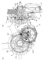
図7(a)及び(b)に示す補助動力ユニット11は、スプロケット2に同軸に連結されたアシストギア30と、電動力を出力する電動モーター37と、該電動モーターの出力軸37aからアシストギア30までギアを介して電動力を伝達するためのギア機構40と、を備える。従って、電動モーター37が回転されると、そのトルクがギア機構40を介してアシストギア30に提供され、該アシストギア30に対し固定された、踏力により回転されるスプロケット2に直ちに伝達される。かくして、補助動力及び踏力の合力が達成される。
The
ギア機構40は、電動モーター37の出力軸37aに連動する第1のギア38と、該第1のギア38と噛み合う、減速用の第2のギア42と、該第2のギア42に同軸に連結され、アシストギア30と噛み合う第3のギア45と、を備える。
The
なお、電動モーター37からアシストギア30への補助動力の伝達経路の途中には、一方向にだけ動力を伝達する、いわゆる一方向クラッチ(図示せず)が設けられている。この一方向クラッチは、電動モーター37からの補助動力をアシストギア30に伝達するが、その逆方向、即ちアシストギア30から電動モーター37へはトルクを伝達しないように構成・接続される。電動モーター37が回転していないときは、図示しない上記一方向クラッチにより、モーターの回転負荷はアシストギア30に伝達されることがなく、軽快な運転が可能となる。
A so-called one-way clutch (not shown) that transmits power only in one direction is provided in the transmission path of auxiliary power from the
スプロケット2と、アシストギア30と、電動モーター37と、ギア機構40と、は共通ベース50上に取り付けられている。また、電動モーター37及びギア機構40全体は、共通ベース50に対して動かないように固定されている。更に、電動モーター37、並びに、ギア機構40のうち第1のギア38及び第2のギア42は、駆動ハウジング13により覆われている。この駆動ハウジング13は、共通ベース50に連結され若しくは該共通ベース50と一体に成形されている。
The
スプロケット2は、ドライブシャフト4に一方向クラッチ99を介して共通ベース50上に回転可能に取り付けられている。一方向クラッチ99は、後述するようにドライブシャフト4に適用された前進方向の回転のみをスプロケット2に伝達する。ドライブシャフト4は、シャフトハウジング52内で、回転可能に軸支され、該シャフトハウジング52は、車体フレームに形成されたシャフト孔80内に挿入された状態で該車体フレームに固定されている。シャフトハウジング52は、共通ベース50に連結され若しくは一体成形されている。
The
スプロケット2とアシストギア30とは、ピン123(図7(a)の例では、120度間隔で3箇所)を介して同軸に連結されている。これによって、アシストギア30に伝達された電動力は、ピン123を介してスプロケット2に伝達する。ピン123は、図7(b)に示されるように、アシストギア30及びスプロケット2を厚さ方向に貫通して取り付けられている。図7(b)の例では、ピン123の脚部は、アシストギア30の孔部に挿入、固定されており、ピン123のヘッド部は、スプロケット2に形成された孔を貫通しており、抜け防止のためピン123の先端は、該孔の直径より大きい直径を有している。
The
また、ゴム等の弾性部材129が、ピン123のヘッド部及び軸部の周囲に設けられている。即ち、弾性部材は、スプロケット2とピン123との間の係合領域に設けられている。これにより、アシストギア30やスプロケット2のガタ揺れ等を吸収し、アシストギア30とスプロケット2との間の動力伝達を非常に円滑にすることができる。
Further, an
なお、スプロケット2とアシストギア30と間の連結手段は、図示のピンに限定されるものではない。例えば、ボルトでもよく、或いはピン123の脚部が、アシストギア30に一体形成されていてもよい。また、弾性部材129は、アシストギア30、ピン123及びスプロケット2の任意の動力伝達経路上に設けられていてもよい。例えば、アシストギア30とピン123との間の係合領域等に単独で又は追加的に設けられてもよい。
The connecting means between the
また、アシストギア30は、スプロケット2とは独立に、本発明の実施例に係るベアリング70を介して共通ベース50に回転可能に取り付けられている。これにより、アシストギア30からスプロケット2へのより安定した動力伝達が可能となる。
The
ベアリング70は、ボール73、74を各々収容した一対の収容部71、72を、共通ベース50の一部である底プレート77上に配置し、アシストギア30の中央ボアの内周壁部をボール73、74に当接させることによって構成される。更には、本ベアリング70では、収容部71の平坦区分を共通ベース50の一部である後プレート75と、アシストギア30との間に配置し、収容部72の平坦区分を、アシストギア30と、アシストギア30に連結した覆いプレート76との間に配置させている。
In the
以上のように、スプロケット2と、アシストギア30と、電動モーター37と、ギア機構40と、ドライブシャフト4とを共通ベース50上に取り付け、更に、図6に示す制御系の回路及び後述する踏力センサーを各々駆動ハウジング13及び一方向クラッチ99内部に取り付けることにより、電動アシストに必要となる全ての構成要素を組み込んだ1つの補助動力ユニット11を構成することが可能となる。それにより、補助動力機構全体の簡素化を達成できると共に、補助動力ユニット11の車体フレームへの取り付けを容易にすることができる。なお、共通ベースを適宜加工することにより、任意形式の車体フレームに、当該補助動力ユニット11を取り付けることができることが理解されよう。
As described above, the
補助動力ユニット11を自転車フレームに取り付ける手順を図8を用いて説明する。図8(a)には、補助動力ユニット11を自転車フレームに取り付けたときの右側から見た斜視図、図8(b)には、図8(a)に示す補助動力ユニット11の拡大図、図8(f)は、補助動力ユニット11を自転車フレームに取り付けたときの左側から見た斜視図が示されている。
The procedure for attaching the
先ず、図8(c)に示すように、シャフト孔80の一方の端部から、補助動力ユニット11のドライブシャフト4(シャフトハウジング52により覆われている)を矢印の方向に沿って挿入する。次に、図8(d)に示すように、シャフト孔80の反対側の端部からドライブシャフト4及びシャフトハウジング52の先端が突出するまで補助動力ユニット11を挿入し、その突出先端に、取り付け金具82及び締め金具84を取り付ける。更に、両端部にボルト螺合用孔が形成された隆起部を補助動力ユニット11に設け、ボルト孔が各々形成され、平行に延在する一対のタブを車体フレームに設けておき、図8(b)の工程で、該隆起部を該一対のタブの間にボルト孔が整列された状態で配置するようにしてもよい。
First, as shown in FIG. 8C, the drive shaft 4 (covered by the shaft housing 52) of the
最後に、図8(c)に示すように、締め金具84をドライブシャフト4及びシャフトハウジング52の先端部に締め付けてこれらを固定すると共に、締め金具84により同時に締め付けられる取り付け金具82の先端部を補助動力ユニット11の外側にボルト止めする。また、一対のタブ内に配置された隆起部のボルト螺合孔に両端部からボルトを締め付ける。以上のように、確実且つ簡単に補助動力ユニット11を車体フレームに取り付けることができる。
(踏力検出機構)
マイクロコンピュータ14に入力される歪みゲージ信号1、2を出力する踏力検出機構を図7乃至図11を用いて説明する。この踏力検出機構は、踏力に応じた一方向クラッチ99の変形によって変化する歪みを検出する。
Finally, as shown in FIG. 8C, the
(Treading force detection mechanism)
A pedal force detection mechanism for outputting strain gauge signals 1 and 2 input to the
図7(b)に示すように、スプロケット2は、一方向クラッチ99を介してドライブシャフト4に軸支される。この一方向クラッチ99は、図9に示すように、駒部100及び歯部112を備える。
As shown in FIG. 7B, the
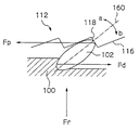
駒部100では、3つのラチェット駒102が周方向に沿って等角度毎にその第2の係合面110に配置されている。このラチェット駒102は剛体でできており、第2の係合面110の略径方向に沿った軸の回りに回動可能とされている。ラチェット駒102は、ラチェット駒102に力が作用していないとき、その長さ方向が第2の係合面110に対して所定の角度をなす(図10の平衡方向160)ように駒立ち上げスプリング104によって付勢されている。図10に示すように、ラチェット駒102が平衡方向160から上昇方向a又は下降方向bに偏倚するとき、駒立ち上げスプリング104は、その偏倚を平衡方向160に戻すようにラチェット駒102に僅かな弾性力を及ぼす。
In the
また、駒部100の中央部には、ドライブシャフト4を受け入れるための駒部ボア106が形成され、この駒部ボア106は、駒部100の裏面101から突出した円筒部103も貫通している。裏面101には、円筒部103の外周囲に円状溝155(図7(b))が形成され、該円状溝155の中には、多数の鋼球152が回転自在に嵌め込まれている。これによって、裏面101には、軸方向の荷重受け兼滑り軸受け用のベアリングが形成される。
A piece bore 106 for receiving the
皿バネ124が、その中心孔127に円筒部103を通して駒部100の裏面101に当接される。このとき、皿バネ124は、駒部100からの圧力に弾力で対抗する方向に鋼球152即ち荷重受けベアリングを介して裏面101に滑動可能に接する。皿バネ124の表面には、180度の位置関係で対向する2個所に、歪みゲージ126が設置される。これらの歪みゲージ126は、リード線128を介してマイクロコンピュータ14に電気的に接続される。更に好ましくは、3個以上の歪みゲージを皿バネ124に設置してもよい。このとき、複数の歪みゲージを、皿バネ124の表面上で夫々が回転対称の位置となるように設置するのが好ましい。
The
皿バネ124は、椀状の支持器130の内底部132に収められる。支持器130には、ドライブシャフト4を貫通させるための支持ボア133及び後面から突出する支持円筒部134が形成される。支持円筒部134の外周表面には、ねじが切ってあり、これを車体取り付け部145のねじ切り内壁に螺合することによって、支持器130が車体に固定される。この支持円筒部134の内壁には、軸方向及び径方向の両荷重対応のベアリング138が係合され(図7(b)参照)、ベアリング138は、ドライブシャフト4に形成されたストッパー斜面144によって係止される。同様に、ドライブシャフト4の反対側にもベアリング(図7(b)参照)が取り付けられるので、ドライブシャフト4は車体に対して回転自在となる。
The
駒部ボア106の内壁には、軸方向5に延びる第1の回転防止用溝108が4個所に形成されている。駒部ボア106の内壁と摺接するドライブシャフト4の外壁部分にも、第1の回転防止用溝108と対面するように軸方向5に延びる第2の回転防止用溝140が4個所に形成されている。図11(a)に示すように、第1の回転防止用溝108及びこれに対面する第2の回転防止用溝140は、軸方向に沿って延びる円柱溝を形成し、各々の円柱溝の中には、これを埋めるように多数の鋼球150が収容される。これによって、駒部100は、軸方向5に沿って摩擦抵抗最小で移動できると共に、ドライブシャフト4に対する相対回転が防止される。これは、一種のボールスプラインであるが、他の形式のボールスプライン、例えば無端回動のボールスプラインなどを、このような摺動可能な回転防止手段として適用することができる。
Four first
また、駒部100のドライブシャフト4への取り付け方法として、図11(a)のボールスプライン以外の手段を用いることも可能である。例えば、図11(b)に示すように、軸方向に延びる突起部140aをドライブシャフト4に設け、該突起部140aを収容する第3の回転防止用溝108aを駒部100に形成する、いわゆるキースプライン形式も回転防止手段として適用可能である。なお、図11(b)において、突起部140aを駒部100側に、第3の回転防止用溝108aをドライブシャフト4側に設けてもよい。更に、図11(c)に示すように、軸方向に延びる第4の回転防止用溝108b及びこれに対面する第5の回転防止用溝140bを駒部100及びドライブシャフト4に夫々設け、これらの溝が形成する直方体状の溝の中にキープレートを収容する、いわゆるキー溝形式も回転防止手段として適用可能である。
Further, as a method of attaching the
歯部112の第1の係合面121には、ラチェット駒102と係合するための複数のラチェット歯114が形成されている。ラチェット歯114は、歯部の周方向に沿って互い違いに周期的に形成された、第1の係合面121に対してより急な斜面118と、より緩やかな斜面116と、から構成される。
A plurality of ratchet teeth 114 for engaging with the
歯部112は、その第1の係合面121を駒部100の第2の係合面110に対面させるようにドライブシャフト4にカラー111を介して摺接可能に軸支される。このとき、ラチェット駒102とラチェット歯112とが係合される(図10)。即ち、ドライブシャフト4は、ラチェット駒102とラチェット歯112との係合部分を介してのみ歯部112と作動的に連結される。カラー111を介して歯部ボア120を通過したドライブシャフト4の端部142には、歯部112が軸方向外側にずれないようワッシャー122が嵌合される(図7(b))。歯部112には、スプロケット2がピン123(図7(b))を介して動かないように取り付けられ、更に、ドライブシャフト4の先端にはペダル軸146が取り付けられる。かくして、車体前進方向のペダル踏力による回転のみをスプロケット2に伝達するようにドライブシャフト4とスプロケット2とを連結するラチェットギアが完成する。
The
好ましくは、オフセット用バネ136が、ドライブシャフト4のストッパー斜面144と、駒部100の裏面101との間に介在されるのがよい。このオフセット用バネ136は、ペダル踏力が所定値以下の場合(例えば事実上ゼロに近い場合)、裏面101に収容された鋼球152と皿バネ124との間にクリアランスを生じさせるように駒部100を軸方向に偏倚させる。
Preferably, the offset
次に、本踏力検出機構の作用を説明する。 Next, the operation of this pedal effort detection mechanism will be described.
搭乗者がペダル8R、8L(図5)にペダル踏力を与え、ドライブシャフト4を車体前進方向に回転させると、この回転力は、ドライブシャフト4に対し回転不可能且つ摺動可能に軸支された駒部100に伝達される。このとき、図10に示すように、ラチェット駒102は、駒部100からペダル踏力に対応する力Fdを与えられので、その先端部は歯部112のラチェット歯のより急な斜面118に当接し、この力をラチェット歯に伝達しようとする。ラチェット歯部112は、スプロケット2に連結されているので、ラチェット駒102の先端部は、駆動のための負荷による力Fpをより急な斜面118から受ける。その両端部から互いに反対向きの力Fp及びFdを与えられたラチェット駒102は、a方向に回転して立ち上がる。このとき駒部100は、ラチェット駒102の立ち上がりによって軸方向内側に移動し、駒部100と支持器130との間に介在する皿バネ124を押し込む。皿バネ124は、これに対抗して弾性力Frを駒部100に作用する。この力Frと、駒部100を軸方向に移動させるペダル踏力を反映した力とは短時間で釣り合う。かくして、皿バネ124の応力歪み、駒部100と歯部112との間のクリアランス、ラチェット駒102の第2の係合面110に対する角度、駒部100の車体フレームに対する位置及び皿バネ124が押し込まれる圧力などはペダル踏力を反映する物理量となる。従って、これらのうち少なくとも1つを検出することによって踏力Tを推定することが可能となる。
When the rider applies a pedaling force to the
本例では、一例として皿バネ124の応力歪みを検出するものである。マイクロコンピュータ14は、皿バネ124に設けられた2つの歪みゲージ126からの信号を少なくとも加算演算する(平均演算を含む)。このように複数箇所の応力歪み量を平均化して計測することによって、同じ踏力でも出力変化を大きくとれ且つノイズ成分を平滑化することができるので、SN比を改善し、踏力推定精度を更に向上させることができる。この効果は、歪みゲージの個数が増えるほど大きくなる。
In this example, the stress strain of the
また、ペダル踏力が所定値以下の場合などでは、オフセット用バネ136は、駒部100の裏面101と皿バネ124との間にクリアランスを生じさせているため、鋼球152が皿バネ124に頻繁に衝突することが少なくなる。これによって、歪みゲージ信号のノイズ成分が軽減して、踏力検出及び電動アシスト制御の安定性を向上させることができる。
Further, when the pedal depression force is less than a predetermined value, the offset
次に、マイクロコンピュータ14は、少なくとも演算された踏力Tに基づいて印加すべきアシスト用の補助動力Teを演算し、該補助動力で回転駆動するように電動モーター37を指令する制御信号を演算出力する。好ましくは、マイクロコンピュータ14は、回転速度センサー220により検出された回転速度信号を車速に変換し、踏力T及び車速の両方に基づいて適切な補助動力Teを決定し、該補助動力Teを発生させるよう電動モーター37を制御する。
Next, the
上記した踏力検出機構には以下のような更に優れた効果がある。
(1) 一方向クラッチと踏力検出機構とを一つの機構で実現したので、部品点数の削減化が図られ、小型、軽量化及び低コストを達成できる。
(2) 踏力を検出する部分に、受け荷重ユニットと荷重検出センサーとを一体化した皿バネを用い、2つの機能を1ユニットで実現したので、上記効果に加えて更に小型、軽量化及び低コストを達成できる。
(3) 上記項目(1)及び(2)に示したように踏力検出機構の小型、軽量化及び簡素化をより高いレベルで達成したので、通常の自転車であっても踏力検出機構を取り付ける可能性が更に広がった。
(4) 上記項目(1)及び(2)で示した理由により、従来機構に比べて荷重の伝達ロスが少なくなり、制御の応答性のよいアシストフィーリングを実現できる。
(5) 上記項目(1)及び(2)で示した理由により、従来機構(コイルバネ使用)に比べ、ペダルに無駄な動き(センサーが感知するまで)が無くなり、ペダルを踏み込んだときのフィーリングは、従来機構は踏み込み時に弾力感があったのに対し、上記例では、通常の自転車のフィーリングと同様になった。
The above pedal force detection mechanism has the following more excellent effects.
(1) Since the one-way clutch and the pedaling force detection mechanism are realized by one mechanism, the number of parts can be reduced, and a reduction in size, weight and cost can be achieved.
(2) The disc spring that integrates the load receiving unit and the load detection sensor is used for the part that detects the treading force, and the two functions are realized in one unit. Cost can be achieved.
(3) As shown in the above items (1) and (2), the pedal force detection mechanism has been made smaller, lighter, and simplified at a higher level. Sex has further expanded.
(4) For the reasons described in the above items (1) and (2), the load transmission loss is reduced as compared with the conventional mechanism, and an assist feeling with good control responsiveness can be realized.
(5) For the reasons shown in the above items (1) and (2), there is no unnecessary movement (until the sensor senses) the pedal compared to the conventional mechanism (using a coil spring), and the feeling when the pedal is depressed The conventional mechanism had a feeling of elasticity when depressed, whereas in the above example, it was the same as the feeling of a normal bicycle.
なお、一方向クラッチ99の駒及び歯のいずれか一方をスプロケットに取り付け、他方をドライブシャフトに取り付けるかは、任意好適に変更可能である。例えば駒部100をスプロケット側に取り付け、歯部112をドライブシャフト4に摺動可能且つ回転不可能に取り付け、歯部112によって皿バネ124を押し込めるようにしてもよい。
It should be noted that whether one of the piece and the teeth of the one-way clutch 99 is attached to the sprocket and the other is attached to the drive shaft can be arbitrarily changed. For example, the
また、上記例では、皿バネの応力歪みを踏力に関連する物理量として検出したが、本発明は、これに限定されず、一方向クラッチ99の踏力に応じた変形によって変化する任意の物理量を検出することができる。例えば、ラチェット駒の傾き、ラチェット駒部及びラチェット歯部の相対間隔、ラチェット駒部及びラチェット歯部のいずれかの車体に対する位置、並びに、皿バネを押す圧力などを、踏力を反映する物理量として選択することができる。 Further, in the above example, the stress distortion of the disc spring is detected as a physical quantity related to the pedaling force. However, the present invention is not limited to this, and an arbitrary physical quantity that changes due to deformation according to the pedaling force of the one-way clutch 99 is detected. can do. For example, the inclination of the ratchet piece, the relative distance between the ratchet piece part and the ratchet tooth part, the position of the ratchet piece part and the ratchet tooth part with respect to the vehicle body, and the pressure for pressing the disc spring are selected as physical quantities reflecting the pedaling force. be able to.
更に、一方向クラッチ99の変形に対抗して配置される弾性体も任意好適に種類及びその形状を変更可能である。皿バネやコイルバネ以外に例えばゴム弾性体などを用いることもできる。また、応力歪みを検出する手段として、歪みゲージを例にしたが、応力歪みに関連した物理量を検出できれば、これに限定されるものではない。 Furthermore, the type and shape of the elastic body arranged against the deformation of the one-way clutch 99 can be arbitrarily and suitably changed. For example, a rubber elastic body can be used in addition to the disc spring and the coil spring. Further, as a means for detecting stress strain, a strain gauge is taken as an example, but the present invention is not limited to this as long as a physical quantity related to stress strain can be detected.
以上が本発明の実施例であるが、本発明は、上記例にのみ限定されるものではなく、本発明の要旨の範囲内において任意好適に変更可能である。 The above is the embodiment of the present invention, but the present invention is not limited to the above-described example, and can be arbitrarily modified within the scope of the gist of the present invention.
1 電動アシスト自転車
2 スプロケット
4 ドライブシャフト
11 補助動力
12 チェーン
13 駆動ハウジング
14 マイクロコンピュータ
15 増幅回路
17 バッテリー
22 駆動輪(後輪)
30 アシストギア
37 電動モーター
37a 電動モーターの出力軸
38 第1のギア
40 ギア機構
42 第2のギア
45 第3のギア
50 共通ベース
52 シャフトハウジング
70 ベアリング
80 シャフト孔
99 一方向クラッチ
100 駒部
102 ラチェット駒
112 歯部
114 ラチェット歯
123 ピン
124 皿バネ
126 歪みゲージ
129 弾性部材
200 ベアリング(第1の実施形態)
202 支持体
203 環状側部
204 回転体
206、208 収容部
207 環状側壁
209 回転体の周端部
210 ボール
211 環状溝
212、216 平坦区分
214、218 湾曲区分
250 ベアリング(第2の実施形態)
202a 支持体
206a、208a 収容部
DESCRIPTION OF
30
40
202
Claims (20)
前記一対の収容部の各々は、環状の平坦区分と、該平坦区分から軸方向に延在してボールを収容するように湾曲された湾曲区分と、を有し、該平坦区分及び該湾曲区分は、前記複数のボールが周方向に並んで配置される環状溝を形成し、前記平坦区分のエッジの高さは、収容されたボールの高さよりも高く、前記湾曲区分のエッジの高さは収容されたボールの高さよりも低く、
前記一対の収容部は、一方の収容部の湾曲区分が他方の収容部の湾曲区分と向き合った状態で、前記支持体に嵌合され、
前記回転体は、一対の前記平坦区分の間に前記ボールと当接した状態で配置され、該回転体は、前記ボール上を滑動することにより前記支持体に対して回転可能となる、ベアリング。 A bearing comprising a pair of annular accommodating portions for accommodating a plurality of balls in order to rotatably support a rotating body with respect to a support,
Each of the pair of receiving portions includes an annular flat section and a curved section that extends in the axial direction from the flat section and is curved to receive the ball, the flat section and the curved section. Form an annular groove in which the plurality of balls are arranged side by side in the circumferential direction, the height of the edge of the flat section is higher than the height of the accommodated ball, and the height of the edge of the curved section is Less than the height of the contained ball,
The pair of housing portions are fitted to the support body in a state where the curved section of one housing portion faces the curved section of the other housing portion,
The rotating body is disposed in contact with the ball between a pair of flat sections, and the rotating body is rotatable with respect to the support body by sliding on the ball.
前記一対の収容部は、該湾曲区分の底部が前記支持体の外周壁上に載置された状態で該支持体の径方向外側に嵌合され、前記回転体は前記中央孔の内周壁が前記ボールと接触した状態で該ボール上を滑動可能に配置される、請求項1乃至8のいずれか1項に記載のベアリング。 The pair of storage portions is configured to be radially inward of the ball in which the bottom of the curved section is stored, and the rotating body has a central hole,
The pair of accommodating portions are fitted to the outer side in the radial direction of the support body with the bottom of the curved section placed on the outer peripheral wall of the support body, and the rotating body has an inner peripheral wall of the central hole. The bearing according to any one of claims 1 to 8, wherein the bearing is slidably disposed on the ball in contact with the ball.
前記一対の収容部は、該湾曲区分の底部が前記支持体の中央孔の内周壁上に載置された状態で該支持体の中央孔内に嵌合され、前記回転体は該回転体の外周壁が前記ボールと接触した状態で該ボール上を滑動可能に配置される、請求項1乃至8のいずれか1項に記載のベアリング。 The support has a central hole, and the pair of storage portions are configured to be radially outward from the ball in which the bottom of the curved section is stored,
The pair of accommodating portions are fitted in the center hole of the support body in a state where the bottom of the curved section is placed on the inner peripheral wall of the center hole of the support body, and the rotating body is The bearing according to any one of claims 1 to 8, wherein an outer peripheral wall is slidably arranged on the ball in contact with the ball.
複数のボールを収容する一対の収容部であって、前記一対の収容部の各々は、環状の平坦区分と、該平坦区分から軸方向に延在してボールを収容するように湾曲された環状の湾曲区分と、を有し、該平坦区分及び該湾曲区分は、前記複数のボールが周方向に並んで配置される環状溝を形成し、前記平坦区分のエッジの高さは、収容されたボールの高さよりも高く、前記湾曲区分のエッジの高さは収容されたボールの高さよりも低い、前記一対の収容部を用意し、
前記一対の収容部のうち一方を、前記支持体に嵌合し、
前記回転体を、嵌合された前記収容部に収容されたボールと当接するように載置し、
前記一対の収容部のうち他方の収容部の湾曲区分が前記一方の収容部の湾曲区分と向き合うように、該他方の収容部を前記支持体に嵌合し、これによって、前記回転体は、前記一対の収容部の平坦区分の間に前記ボールと当接した状態で配置され、該回転体は、前記ボール上を滑動することにより前記支持体に対して回転可能となる、各工程を備える、方法。 A method of bearing a rotating body rotatably with respect to a support,
A pair of accommodating portions for accommodating a plurality of balls, each of the pair of accommodating portions, an annular flat section, and an annular shape that extends in an axial direction from the flat section and accommodates the balls The flat section and the curved section form an annular groove in which the plurality of balls are arranged side by side in a circumferential direction, and the height of the edge of the flat section is received Preparing the pair of accommodating portions higher than the height of the ball, wherein the height of the edge of the curved section is lower than the height of the accommodated ball;
One of the pair of accommodating portions is fitted to the support,
The rotating body is placed so as to come into contact with the ball accommodated in the accommodating portion fitted,
The other housing portion is fitted to the support body so that the curved section of the other housing portion of the pair of housing portions faces the curved section of the one housing portion. It is disposed in contact with the ball between the flat sections of the pair of receiving portions, and the rotating body is capable of rotating with respect to the support body by sliding on the ball. ,Method.
前記一方の収容部を前記支持体に嵌合する工程は、該一方の収容部を該収容部の湾曲区分の底部が該支持体の外周壁上に載置されるように該支持体の径方向外側に嵌合する工程を備え、
前記回転体を載置する工程は、該回転体の中央孔の内周壁が前記一方の収容部に収容されたボールと接触するように、該回転体を載置する工程を備え、
前記他方の収容部を前記支持体に嵌合する工程は、該他方の収容部を該収容部の湾曲区分の底部が該支持体の外周壁上に載置されるように該支持体の径方向外側に嵌合し、該回転体の中央孔の内周壁を前記一方及び他方の収容部に収容されたボールと接触させ、これによって該回転体を該ボール上で滑動可能にする工程を備える、請求項11乃至18のいずれか1項に記載の方法。 The pair of storage portions is configured to be radially inward of the ball in which the bottom of the curved section is stored, and the rotating body has a central hole,
The step of fitting the one accommodating portion into the support is performed by adjusting the diameter of the support so that the bottom of the curved section of the accommodating portion is placed on the outer peripheral wall of the support. A step of fitting outward in the direction,
The step of placing the rotating body includes the step of placing the rotating body such that an inner peripheral wall of a central hole of the rotating body is in contact with a ball housed in the one housing portion,
The step of fitting the other accommodating portion into the support is performed by adjusting the diameter of the support so that the bottom of the curved section of the accommodating portion is placed on the outer peripheral wall of the support. Fitting the outer side in the direction, and bringing the inner peripheral wall of the central hole of the rotating body into contact with the balls accommodated in the one and the other accommodating portions, thereby enabling the rotating body to slide on the balls The method according to any one of claims 11 to 18.
前記一方の収容部を前記支持体に嵌合する工程は、該一方の収容部を該収容部の湾曲区分の底部が該支持体の中央孔の内周壁上に載置されるように該支持体に嵌合する工程を備え、
前記回転体を載置する工程は、該回転体の外周壁が前記一方の収容部に収容されたボールと接触するように、該回転体を載置する工程を備え、
前記他方の収容部を前記支持体に嵌合する工程は、該他方の収容部を該収容部の湾曲区分の底部が該支持体の中央孔の内周壁上に載置されるように該支持体に嵌合し、該回転体の外周壁を前記一方及び他方の収容部に収容されたボールと接触させ、これによって該回転体を該ボール上で滑動可能にする工程を備える、請求項11乃至18のいずれか1項に記載の方法。 The support has a central hole, and the pair of storage portions are configured to be radially outward from the ball in which the bottom of the curved section is stored,
The step of fitting the one accommodating portion into the support body includes supporting the one accommodating portion so that the bottom portion of the curved section of the accommodating portion is placed on the inner peripheral wall of the central hole of the supporting member. A process of fitting into the body,
The step of placing the rotating body includes a step of placing the rotating body such that an outer peripheral wall of the rotating body is in contact with a ball accommodated in the one accommodating portion,
The step of fitting the other housing portion to the support body includes supporting the other housing portion so that the bottom of the curved section of the housing portion is placed on the inner peripheral wall of the central hole of the support body. The method includes the steps of: fitting to a body; and contacting an outer peripheral wall of the rotating body with a ball accommodated in the one and the other accommodating portions, thereby enabling the rotating body to slide on the ball. The method of any one of thru | or 18.
Priority Applications (1)
| Application Number | Priority Date | Filing Date | Title |
|---|---|---|---|
| JP2006069184A JP2007247703A (en) | 2006-03-14 | 2006-03-14 | Bearing and method for bearing shaft of rotor |
Applications Claiming Priority (1)
| Application Number | Priority Date | Filing Date | Title |
|---|---|---|---|
| JP2006069184A JP2007247703A (en) | 2006-03-14 | 2006-03-14 | Bearing and method for bearing shaft of rotor |
Publications (1)
| Publication Number | Publication Date |
|---|---|
| JP2007247703A true JP2007247703A (en) | 2007-09-27 |
Family
ID=38592227
Family Applications (1)
| Application Number | Title | Priority Date | Filing Date |
|---|---|---|---|
| JP2006069184A Pending JP2007247703A (en) | 2006-03-14 | 2006-03-14 | Bearing and method for bearing shaft of rotor |
Country Status (1)
| Country | Link |
|---|---|
| JP (1) | JP2007247703A (en) |
Cited By (1)
| Publication number | Priority date | Publication date | Assignee | Title |
|---|---|---|---|---|
| JP2013103507A (en) * | 2011-11-10 | 2013-05-30 | Gokiso Giken Ltd | Crank shaft device for bicycle |
-
2006
- 2006-03-14 JP JP2006069184A patent/JP2007247703A/en active Pending
Cited By (1)
| Publication number | Priority date | Publication date | Assignee | Title |
|---|---|---|---|---|
| JP2013103507A (en) * | 2011-11-10 | 2013-05-30 | Gokiso Giken Ltd | Crank shaft device for bicycle |
Similar Documents
| Publication | Publication Date | Title |
|---|---|---|
| JP4235446B2 (en) | One-way clutch and torque detector using the same | |
| JP3910442B2 (en) | Power assist bicycle | |
| JP5203939B2 (en) | Torque detection device and electrically assisted bicycle | |
| JP4875337B2 (en) | Electric assist bicycle and electric assist bicycle unit that can be attached to the body frame of the bicycle | |
| JP2003194194A (en) | Gear box and motor-assisted bicycle using the same | |
| JP2009166509A (en) | Battery bracket for electrically assisted bicycle, and electrically assisted bicycle using the battery bracket | |
| EP1923683A1 (en) | Rotation detector and torque sensor | |
| JP6226152B2 (en) | Electric assist bicycle | |
| JPWO2008120311A1 (en) | Electric assist bicycle and electric assist bicycle unit that can be attached to the body frame of the bicycle | |
| JP2008254592A (en) | Power-assisted bicycle | |
| JP2007247703A (en) | Bearing and method for bearing shaft of rotor | |
| JPWO2002076813A1 (en) | Rotational speed sensor and power assisted bicycle equipped with the sensor | |
| JP2006143216A (en) | Power-assisted bicycle | |
| JP3777086B2 (en) | Power assist bicycle | |
| JP3872660B2 (en) | Electric assist bicycle | |
| JP2003019996A (en) | Pedal effort detecting device of bicycle with electric assist motive power | |
| JP5968267B2 (en) | Crankshaft assembly and electric assist bicycle equipped with the same | |
| JP4206148B2 (en) | Assist power transmission device for power assist vehicle | |
| JP2002308177A (en) | Chain catch prevention device, bicycle, and power-assisted bicycle | |
| JP2002362468A (en) | Power-assisted bicycle, and electric bicycle | |
| JP2000131161A (en) | Torque detector and motor assisted bicycle equipped with torque detector | |
| JPH08313375A (en) | Torque detecting device for bicycle | |
| JP2003054481A (en) | Bicycle with driving unit and unit mounting bracket | |
| JP2002362471A (en) | Power-assisted bicycle, and power bicycle having operation switch | |
| WO2001054966A1 (en) | Power-assisted bicycle, drive device, and drive sprocket |