JP2007247486A - Failure diagnostic system of exhaust emission control device of internal combustion engine - Google Patents
Failure diagnostic system of exhaust emission control device of internal combustion engine Download PDFInfo
- Publication number
- JP2007247486A JP2007247486A JP2006070232A JP2006070232A JP2007247486A JP 2007247486 A JP2007247486 A JP 2007247486A JP 2006070232 A JP2006070232 A JP 2006070232A JP 2006070232 A JP2006070232 A JP 2006070232A JP 2007247486 A JP2007247486 A JP 2007247486A
- Authority
- JP
- Japan
- Prior art keywords
- fuel ratio
- air
- catalytic converter
- bypass
- rich
- Prior art date
- Legal status (The legal status is an assumption and is not a legal conclusion. Google has not performed a legal analysis and makes no representation as to the accuracy of the status listed.)
- Granted
Links
Images


Classifications
-
- Y02T10/47—
Abstract
Description
この発明は、冷間始動直後に、排気系の比較的上流に触媒コンバータを備えたバイパス通路側に流路切換弁により排気を案内するようにした排気浄化装置に関し、特に、その流路切換弁の漏洩を診断する故障診断装置に関する。 The present invention relates to an exhaust gas purification device in which exhaust gas is guided by a flow path switching valve to a bypass passage side provided with a catalytic converter relatively upstream of an exhaust system immediately after a cold start, and in particular, the flow path switching valve. The present invention relates to a failure diagnosis device for diagnosing leakage of a liquid.
従来から知られているように、車両の床下などの排気系の比較的下流側にメイン触媒コンバータを配置した構成では、内燃機関の冷間始動後、触媒コンバータの温度が上昇して活性化するまでの間、十分な排気浄化作用を期待することができない。また一方、触媒コンバータを排気系の上流側つまり内燃機関側に近付けるほど、触媒の熱劣化による耐久性低下が問題となる。 As conventionally known, in a configuration in which the main catalytic converter is disposed relatively downstream of the exhaust system such as under the floor of a vehicle, the temperature of the catalytic converter rises and is activated after a cold start of the internal combustion engine. In the meantime, a sufficient exhaust purification action cannot be expected. On the other hand, the closer the catalytic converter is to the upstream side of the exhaust system, that is, the internal combustion engine side, the lower the durability due to thermal degradation of the catalyst.
そのため、特許文献1や特許文献2に開示されているように、メイン触媒コンバータを備えたメイン流路の上流側部分と並列にバイパス流路を設けるとともに、このバイパス流路に、別のバイパス触媒コンバータを介装し、両者を切り換える切換弁によって、冷間始動直後は、バイパス流路側に排気を案内するようにした排気装置が、従来から提案されている。この構成では、バイパス触媒コンバータは排気系の中でメイン触媒コンバータよりも相対的に上流側に位置しており、相対的に早期に活性化するので、より早い段階から排気浄化を開始することができる。
上記のような構成において、流路切換弁による流路切換が不十分な場合、例えば、メイン通路を開閉する流路切換弁が閉位置にあるにも拘わらず排気が漏洩するような場合には、メイン触媒コンバータが未活性の段階で未浄化の排気がそのまま外部へ流出することになり、好ましくない。従って、流路切換弁の漏洩を診断する診断装置が求められている。 In the above configuration, when the flow path switching by the flow path switching valve is insufficient, for example, when the exhaust gas leaks even though the flow path switching valve that opens and closes the main passage is in the closed position. When the main catalytic converter is inactive, unpurified exhaust gas flows out to the outside as it is, which is not preferable. Accordingly, there is a need for a diagnostic device that diagnoses leakage of the flow path switching valve.
なお、上記特許文献2は、流路切換弁のデポジットの付着による流量低下などを検出する方法を提案しているが、未浄化の排気の漏洩を診断することはできない。
In addition, although the said
この発明は、メイン触媒コンバータを下流側に備えたメイン通路の上流側部分と並列にバイパス通路が設けられるとともに、このバイパス通路にバイパス触媒コンバータを備え、かつ上記メイン通路の上記上流側部分に該メイン通路を閉塞する流路切換弁を備えてなる内燃機関の排気浄化装置において、上記バイパス通路のバイパス触媒コンバータ上流側の排気空燃比を検出する第1の空燃比センサと、上記メイン通路のメイン触媒コンバータ上流側の排気空燃比を検出する第2の空燃比センサと、を備え、上記流路切換弁が閉位置にあるときの両者の検出信号から上記流路切換弁の漏洩を診断することを特徴としている。 According to the present invention, a bypass passage is provided in parallel with the upstream portion of the main passage provided with the main catalytic converter on the downstream side, the bypass passage is provided with the bypass catalytic converter, and the upstream portion of the main passage is provided with the bypass passage. In an exhaust gas purification apparatus for an internal combustion engine comprising a flow path switching valve that closes a main passage, a first air-fuel ratio sensor that detects an exhaust air-fuel ratio upstream of the bypass catalytic converter of the bypass passage, and a main passage of the main passage A second air-fuel ratio sensor for detecting an exhaust air-fuel ratio upstream of the catalytic converter, and diagnosing leakage of the flow path switching valve from both detection signals when the flow path switching valve is in the closed position It is characterized by.
本発明の一つの態様では、リッチ,リーンに周期的に変化するように機関空燃比を制御している間に、第1の空燃比センサにおけるリッチ,リーンの変化に対する第2の空燃比センサにおけるリッチ,リーンの変化の遅れを求め、これに基づいて流路切換弁の漏洩を診断する。 In one aspect of the present invention, while the engine air-fuel ratio is controlled to periodically change between rich and lean, the second air-fuel ratio sensor with respect to the rich and lean change in the first air-fuel ratio sensor. The delay of the change between rich and lean is obtained, and leakage of the flow path switching valve is diagnosed based on this.
また本発明の異なる一つの態様では、リッチ,リーンに周期的に変化するように機関空燃比を制御している間に、第1の空燃比センサにおけるリッチ,リーンの期間の長さと第2の空燃比センサにおけるリッチ,リーンの期間の長さとを比較して、流路切換弁の漏洩を診断する。 In another aspect of the present invention, while the engine air-fuel ratio is controlled so as to periodically change between rich and lean, the length of the rich and lean period in the first air-fuel ratio sensor and the second The leakage of the flow path switching valve is diagnosed by comparing the lengths of the rich and lean periods in the air-fuel ratio sensor.
上記のように機関空燃比をリッチ,リーンに周期的に変化させるには、例えば、上記第1の空燃比センサを用いた空燃比フィードバック制御による機関空燃比の周期的な変化を利用することができる。 In order to periodically change the engine air-fuel ratio to rich and lean as described above, for example, the periodic change of the engine air-fuel ratio by the air-fuel ratio feedback control using the first air-fuel ratio sensor may be used. it can.
あるいは、診断時に、所定の周期で機関空燃比を強制的に周期的に変化させるようにしてもよい。なお、このように強制的に周期変化させる場合でも、平均的空燃比は理論空燃比に維持されるので、診断中の排気エミッションの悪化はない。 Alternatively, the engine air-fuel ratio may be forcibly changed periodically at a predetermined cycle at the time of diagnosis. Even when the cycle is forcibly changed in this way, the average air-fuel ratio is maintained at the stoichiometric air-fuel ratio, so there is no deterioration in exhaust emission during diagnosis.
すなわち、上記構成の排気浄化装置においては、メイン通路を開閉する流路切換弁が閉位置にあると、内燃機関から排出された排気の全量がバイパス通路側へ流れ、バイパス触媒コンバータを通過する。これに対し流路切換弁が開位置にあると、内燃機関から排出された排気の大部分は、通気抵抗の差により、メイン通路側を流れる。 That is, in the exhaust emission control device having the above configuration, when the flow path switching valve that opens and closes the main passage is in the closed position, the entire amount of exhaust discharged from the internal combustion engine flows to the bypass passage side and passes through the bypass catalytic converter. On the other hand, when the flow path switching valve is in the open position, most of the exhaust discharged from the internal combustion engine flows through the main passage due to the difference in ventilation resistance.
流路切換弁の漏洩の診断は、流路切換弁が閉位置にあるときに、例えば空燃比フィードバック制御による機関空燃比の周期的な変化を利用して行われる。第1の空燃比センサはバイパス触媒コンバータの上流側にあるので、機関空燃比が周期的に変化すると、その検出信号は、機関空燃比とともに周期的に変化する。これに対し、バイパス触媒コンバータの下流側では、触媒が有する酸素ストレージ能力により、排気空燃比の変化が相対的に小さくなり、かつ機関空燃比の変化に対し遅れて変化する。 Diagnosis of leakage of the flow path switching valve is performed, for example, using a periodic change in the engine air-fuel ratio by air-fuel ratio feedback control when the flow path switching valve is in the closed position. Since the first air-fuel ratio sensor is on the upstream side of the bypass catalytic converter, when the engine air-fuel ratio changes periodically, the detection signal changes periodically with the engine air-fuel ratio. On the other hand, on the downstream side of the bypass catalytic converter, the change in the exhaust air-fuel ratio becomes relatively small due to the oxygen storage capability of the catalyst, and changes with a delay from the change in the engine air-fuel ratio.
流路切換弁を通した排気の漏洩がなければ、メイン触媒コンバータ上流側の第2の空燃比センサはバイパス触媒コンバータ通過後の排気のみを受けるので、第2の空燃比センサでの検出空燃比は、上述したように、排気空燃比の周期的な変化に対し、遅れて変化し、かつその変化が小さなものとなる。これに対し、流路切換弁を通した排気の漏洩があると、機関から排出された排気がバイパス触媒コンバータを経ることなく第2の空燃比センサに作用するので、第2の空燃比センサの検出空燃比は、排気空燃比ひいては第1の空燃比センサの検出空燃比と同様の周期ならびにタイミングで変化する。仮に機関の排気ポートから第1の空燃比センサおよび第2の空燃比センサまでの通路長の差が無視できるものとすれば、漏洩がある場合に、両者は全く同じタイミングでリッチ,リーンに反転変化することになる。 If there is no leakage of exhaust gas through the flow path switching valve, the second air-fuel ratio sensor upstream of the main catalytic converter receives only the exhaust gas that has passed through the bypass catalytic converter, so the air-fuel ratio detected by the second air-fuel ratio sensor As described above, changes with a delay with respect to the periodic change of the exhaust air-fuel ratio, and the change becomes small. On the other hand, if the exhaust gas leaks through the flow path switching valve, the exhaust gas discharged from the engine acts on the second air-fuel ratio sensor without passing through the bypass catalytic converter. The detected air-fuel ratio changes at the same cycle and timing as the exhaust air-fuel ratio and thus the detected air-fuel ratio of the first air-fuel ratio sensor. If the difference in passage length from the exhaust port of the engine to the first air-fuel ratio sensor and the second air-fuel ratio sensor is negligible, when there is a leak, both are reversed to rich and lean at exactly the same timing. Will change.
従って、リッチ,リーンの変化の遅れ、あるいは、リッチ,リーンの期間の長さ、などによって漏洩の有無あるいはその漏洩の程度などを診断することができる。 Therefore, it is possible to diagnose the presence or absence of leakage or the degree of leakage based on the delay in rich / lean changes or the length of the rich / lean period.
なお、上述した酸素ストレージ能力は、触媒劣化によって影響されるが、触媒劣化の場合には、第1の空燃比センサのリッチ,リーンの変化時期と第2の空燃比センサのリッチ,リーンの変化時期とは完全には一致せず、劣化度合に応じて、その遅れが小さくなるので、漏洩の有無と触媒劣化とは容易に識別が可能である。 Note that the oxygen storage capacity described above is affected by catalyst deterioration, but in the case of catalyst deterioration, the rich / lean change timing of the first air-fuel ratio sensor and the rich / lean change of the second air-fuel ratio sensor. The timing does not completely match, and the delay is reduced according to the degree of deterioration. Therefore, the presence or absence of leakage and catalyst deterioration can be easily distinguished.
この発明に係る内燃機関の排気浄化装置の故障診断装置によれば、流路切換弁を通した排気の漏洩を確実に診断することができ、未浄化の排気の外部への流出を未然に防止することができる。 According to the failure diagnosis apparatus for an exhaust gas purification apparatus for an internal combustion engine according to the present invention, it is possible to reliably diagnose exhaust gas leakage through the flow path switching valve, and to prevent outflow of unpurified exhaust gas to the outside. can do.
特に、診断実行中も理論空燃比を中心としてリッチ,リーンに周期的に変化することから平均的空燃比が理論空燃比もしくはその近傍に維持され、排気エミッションの悪化を伴うことがない。 In particular, even during the execution of the diagnosis, the air-fuel ratio periodically changes from rich to lean around the stoichiometric air-fuel ratio, so that the average air-fuel ratio is maintained at or near the stoichiometric air-fuel ratio, and exhaust emissions do not deteriorate.
以下、この発明を直列4気筒内燃機関の排気浄化装置に適用した一実施例を図面に基づいて詳細に説明する。 Hereinafter, an embodiment in which the present invention is applied to an exhaust purification apparatus for an in-line four-cylinder internal combustion engine will be described in detail with reference to the drawings.
図1は、この内燃機関の排気装置の配管レイアウトならびに制御システムを模式的に示した説明図であり、始めに、この図1に基づいて、排気装置の構成を説明する。 FIG. 1 is an explanatory view schematically showing the piping layout and control system of the exhaust device of the internal combustion engine. First, the configuration of the exhaust device will be described based on FIG.
内燃機関1のシリンダヘッド1aには、直列に配置された♯1気筒〜♯4気筒の各気筒の排気ポート2がそれぞれ側面に向かって開口するように形成されており、この排気ポート2のそれぞれに、メイン通路3が接続されている。♯1気筒〜♯4気筒の4本のメイン通路3は、1本の流路に合流しており、その下流側に、メイン触媒コンバータ4が配置されている。このメイン触媒コンバータ4は、車両の床下に配置される容量の大きなものであって、触媒としては、例えば、三元触媒とHCトラップ触媒とを含んでいる。上記のメイン通路3およびメイン触媒コンバータ4によって、通常の運転時に排気が通流するメイン流路が構成される。また、各気筒からの4本のメイン通路3の合流点には、流路切換手段として各メイン通路3を一斉に開閉する流路切換弁5が設けられている。この流路切換弁5は、適宜なアクチュエータ5aによって開閉駆動される。
In the
一方、バイパス流路として、各気筒のメイン通路3の各々から、該メイン通路3よりも通路断面積の小さなバイパス通路7がそれぞれ分岐している。各バイパス通路7の上流端となる分岐点6は、メイン通路3のできるだけ上流側の位置に設定されている。4本のバイパス通路7は、下流側で1本の流路に合流しており、その合流点の直後に、三元触媒を用いたバイパス触媒コンバータ8が介装されている。このバイパス触媒コンバータ8は、メイン触媒コンバータ4に比べて容量が小さな小型のものであり、望ましくは、低温活性に優れた触媒が用いられる。バイパス触媒コンバータ8の出口側から延びるバイパス通路7の下流端は、メイン通路3におけるメイン触媒コンバータ4上流側でかつ流路切換弁5よりも下流側の合流点9において該メイン通路3に接続されている。
On the other hand, bypass passages 7 each having a smaller passage sectional area than the main passage 3 are branched from the main passages 3 of the respective cylinders as bypass passages. The
ここで、メイン触媒コンバータ4の入口部ならびに出口部には、それぞれメイン上流側空燃比センサ10およびメイン下流側空燃比センサ11が配置されており、バイパス触媒コンバータ8の入口部ならびに出口部には、それぞれバイパス上流側空燃比センサ12およびバイパス下流側空燃比センサ13が配置されている。メイン上流側空燃比センサ10およびメイン下流側空燃比センサ11は、メイン触媒コンバータ4の活性後に公知の空燃比フィードバック制御を行うためのものであり、基本的に上流側空燃比センサ10によって機関空燃比(燃料噴射量)が制御され、その制御特性のばらつきの補正などのために下流側空燃比センサ11の出力信号が利用される。同様に、バイパス上流側空燃比センサ12およびバイパス下流側空燃比センサ13は、バイパス触媒コンバータ8を用いる際に公知の空燃比フィードバック制御を行うためのものであり、基本的に上流側空燃比センサ12によって機関空燃比(燃料噴射量)が制御され、その制御特性のばらつきの補正などのために下流側空燃比センサ13の出力信号が利用される。これらの空燃比センサ10〜13としては、排気空燃比に応じたほぼリニアな出力特性を有するいわゆる広域型空燃比センサ、あるいはリッチ,リーンの2値的な出力特性を有する酸素センサ、のいずれであってもよいが、上述した空燃比制御の際の制御性の上から、上流側空燃比センサ10,12は広域型空燃比センサであることが望ましく、また、下流側空燃比センサ11,13は、部品コストなどの点から酸素センサを用いることが可能である。上記バイパス上流側空燃比センサ12は「第1の空燃比センサ」に相当し、上記メイン上流側空燃比センサ10は「第2の空燃比センサ」に相当する。なお、下流側空燃比センサ11,13を用いた空燃比フィードバック制御の補正制御を行わない場合には、これらの下流側空燃比センサ11,13を省略することも可能である。
Here, a main upstream air-
また内燃機関1は、点火プラグ21を備え、その吸気通路22には、燃料噴射弁23が配置されている。さらに、吸気通路22の上流側に、モータ等のアクチュエータによって開閉駆動される所謂電子制御型スロットル弁24が配置されているとともに、吸入空気量を検出するエアフロメータ25がエアクリーナ26下流に設けられている。
The
内燃機関1の種々の制御パラメータ、例えば、上記燃料噴射弁23による燃料噴射量、点火プラグ21による点火時期、スロットル弁24の開度、流路切換弁5の開閉状態、などは、エンジンコントロールユニット27によって制御される。このエンジンコントロールユニット27には、上述したセンサ類のほか、冷却水温センサ28、運転者により操作されるアクセルペダルの開度(踏込量)を検出するアクセル開度センサ29、などの種々のセンサ類の検出信号が入力されている。そして、上記流路切換弁5の漏洩の診断が上記エンジンコントロールユニット27によって適宜に実行される。
Various control parameters of the
このような構成においては、冷間始動後の機関温度ないしは排気温度が低い段階では、アクチュエータ5aを介して流路切換弁5が閉じられ、メイン通路3が遮断される。そのため、各気筒から吐出された排気は、その全量が分岐点6からバイパス通路7を通してバイパス触媒コンバータ8へと流れる。バイパス触媒コンバータ8は、排気系の上流側つまり排気ポート2に近い位置にあり、かつ小型のものであるので、速やかに活性化し、早期に排気浄化が開始される。
In such a configuration, when the engine temperature or the exhaust temperature after the cold start is low, the flow path switching valve 5 is closed via the
一方、機関の暖機が進行して、機関温度ないしは排気温度が十分に高くなったら、メイン触媒コンバータ4の触媒が活性したとみなし、流路切換弁5が開放される。これにより、各気筒から吐出された排気は、主に、メイン通路3からメイン触媒コンバータ4を通過する。このときバイパス通路7側は特に遮断されていないが、バイパス通路7側の方がメイン通路3側よりも通路断面積が小さく、かつバイパス触媒コンバータ8が介在しているので、両者の通路抵抗の差により、排気流の大部分はメイン通路3側を通り、バイパス通路7側には殆ど流れない。従って、バイパス触媒コンバータ8の熱劣化は十分に抑制される。
On the other hand, when the engine warm-up proceeds and the engine temperature or the exhaust temperature becomes sufficiently high, it is considered that the catalyst of the main catalytic converter 4 has been activated, and the flow path switching valve 5 is opened. Thus, the exhaust discharged from each cylinder mainly passes through the main catalytic converter 4 from the main passage 3. At this time, the bypass passage 7 side is not particularly cut off, but the bypass passage 7 side has a smaller passage cross-sectional area than the main passage 3 side and the bypass
次に、上記流路切換弁5の漏洩の診断について説明する。なお、以下の例では、2つの上流側空燃比センサ10,12が広域型空燃比センサであり、2つの下流側空燃比センサ11,13が酸素センサであって、漏洩診断には、2つの上流側空燃比センサ10,12のみが用いられる。
Next, the diagnosis of leakage of the flow path switching valve 5 will be described. In the following example, the two upstream air-
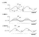
図2は、漏洩診断の一実施例を示すタイムチャートであり、この漏洩診断は、冷間始動後に流路切換弁5が閉じられていて、かつバイパス上流側空燃比センサ12を用いた空燃比フィードバック制御が開始された後(バイパス触媒コンバータ8の活性後)に実行される。バイパス触媒コンバータ8は上述のように速やかに活性化するので、始動後、短時間で空燃比フィードバック制御が開始される。なお、暖機完了後(メイン触媒コンバータ4の活性後)に一時的に流路切換弁5を閉じて診断を行うことも可能である。
FIG. 2 is a time chart showing an embodiment of the leakage diagnosis. This leakage diagnosis is based on the air-fuel ratio in which the flow path switching valve 5 is closed after the cold start and the bypass upstream air-
図2の(a)は、正常時、つまり漏洩がなくかつバイパス触媒コンバータ8の触媒劣化もない状態におけるバイパス上流側空燃比センサ12の検出空燃比AFBとメイン上流側空燃比センサ10の検出空燃比AFMとを対比して示している。公知の空燃比フィードバック制御により、排気空燃比が理論空燃比に収束するように燃料噴射量が周期的に増減変化し、機関空燃比がリッチ,リーンに周期的に変化するが、バイパス上流側空燃比センサ12は、この機関から排出された排気の影響を直接に受けるので、機関空燃比の変化をそのまま反映した出力信号が得られる。つまり、図示するバイパス上流側空燃比センサ12の検出空燃比AFBは、機関空燃比に対応しており、機関空燃比そのものとみなすこともできる。このようなバイパス上流側空燃比センサ12の検出空燃比AFBの周期変化に対し、メイン上流側空燃比センサ10の検出空燃比AFMは、図示するように、理論空燃比を越えてリッチ,リーンとなる期間が短く、かつその変化のタイミングが、バイパス上流側空燃比センサ12の検出空燃比AFBよりも遅れたものとなる。これは、バイパス触媒コンバータ8の触媒の酸素ストレージ能力によるものであり、排気空燃比がリーンとなったときに酸素が吸収され、排気空燃比がリッチとなったときに酸素が放出されるので、排気空燃比がリッチ,リーンに周期変化しても、バイパス触媒コンバータ8下流では、酸素ストレージ能力が飽和するまで、その変化が現れないのである。
FIG. 2A shows the detected air-fuel ratio AFB detected by the bypass upstream air-
これに対し、図2の(b)は、閉位置にある流路切換弁5を通して排気が漏洩している場合の特性を示している。バイパス上流側空燃比センサ12の検出空燃比AFBは、漏洩の有無に影響されないので、(a)の正常時と変わりがない。これに対して、メイン上流側空燃比センサ10には、バイパス触媒コンバータ8を通らずに流路切換弁5から漏洩した排気が作用するので、その検出空燃比AFMは、バイパス上流側空燃比センサ12の検出空燃比AFBと同様のタイミングでもってリッチ,リーンに反転するようになる。なお、リッチ,リーンの値つまり周期変化の振幅は、バイパス触媒コンバータ8を通過した排気と混合して希釈されることから、バイパス上流側空燃比センサ12の検出空燃比AFBの振幅よりも小さなものとなる。
On the other hand, FIG. 2B shows the characteristics when the exhaust gas leaks through the flow path switching valve 5 in the closed position. Since the detected air-fuel ratio AFB of the bypass upstream air-
従って、例えば、バイパス上流側空燃比センサ12の検出空燃比AFBにおけるリッチ,リーンの変化時期に対するメイン上流側空燃比センサ10の検出空燃比AFMにおけるリッチ,リーンの変化の遅れΔtを求め、これが所定の基準値よりも小さい場合には、漏洩と診断することができる。
Therefore, for example, the delay Δt of the rich / lean change in the detected air-fuel ratio AFM of the main upstream air-
あるいは、バイパス上流側空燃比センサ12の検出空燃比AFBにおけるリッチ,リーンの期間の長さt1とメイン上流側空燃比センサ10の検出空燃比AFMにおけるリッチ,リーンの期間の長さt2とを比較して、両者がほぼ等しいときに、漏洩と診断することができる。
Alternatively, the length t1 of the rich / lean period in the detected air-fuel ratio AFB of the bypass upstream air-
勿論、これらの診断は、例えば複数回の空燃比変化についての平均などを求めることによって、より信頼性の高いものとすることができる。なお、図から明らかなように、上記の遅れΔtは、上記の期間t1,t2の差(t1−t2)に実質的に等しい。 Of course, these diagnoses can be made more reliable by obtaining, for example, an average of a plurality of air-fuel ratio changes. As is apparent from the figure, the delay Δt is substantially equal to the difference between the periods t1 and t2 (t1−t2).
一方、図2の(c)は、バイパス触媒コンバータ8の触媒がある程度劣化したときの検出空燃比AFMの変化を示している。図示するように、触媒劣化により酸素ストレージ能力が低下すると、メイン上流側空燃比センサ10の検出空燃比AFMの基本的な傾向は変わらないものの、より早い時期にリッチ,リーンに変化するようになる。つまり、バイパス上流側空燃比センサ12の検出空燃比AFBの変化からの遅れΔtが小さくなり、リッチ,リーンの期間t2も長くなる。ここで、仮に触媒劣化が極端に進行し、酸素ストレージ能力が0となれば、遅れΔtや期間t2は、図2(b)の場合と識別できないが、実際には、触媒劣化は経時的に徐々に進行するので、ある程度劣化した段階では、遅れΔtや期間t2が、図2(a)の特性と図2(b)の特性との中間の値を示す。従って、この段階で触媒劣化と診断することが可能であり、流路切換弁5の漏洩と確実に識別することができる。
On the other hand, FIG. 2C shows a change in the detected air-fuel ratio AFM when the catalyst of the bypass
例えば、上記の遅れΔtが第1の基準値よりも短いときに漏洩ありと診断し、第2の基準値よりも大きいときに漏洩なしと診断し、第1の基準値と第2の基準値との間の所定の範囲(第3の基準値と第4の基準値の間)にあるときには、バイパス触媒コンバータ8の触媒劣化と診断することができる。なお、第3の基準値および第4の基準値を、それぞれ第1の基準値および第2の基準値と等しく設定してもよい。
For example, when the delay Δt is shorter than the first reference value, it is diagnosed that there is leakage, and when it is larger than the second reference value, it is diagnosed that there is no leakage, and the first reference value and the second reference value Is in a predetermined range (between the third reference value and the fourth reference value), the catalyst deterioration of the bypass
あるいは、バイパス上流側空燃比センサ12の検出空燃比AFBにおけるリッチ,リーンの期間の長さt1とメイン上流側空燃比センサ10の検出空燃比AFMにおけるリッチ,リーンの期間の長さt2とを求め、両者がほぼ等しいときに漏洩ありと診断し、期間t2が期間t1よりも十分に短いときに漏洩なしと診断し、期間t2が期間t1に比較して中間のある範囲にあるときには、バイパス触媒コンバータ8の触媒劣化と診断することができる。
Alternatively, the length t1 of the rich / lean period in the detected air-fuel ratio AFB of the bypass upstream air-
このように上記実施例によれば、通常の空燃比フィードバック制御を継続している中で流路切換弁5の漏洩診断を行うことができ、診断中の排気エミッションの悪化を伴うことがない。また、触媒劣化と識別して、精度の高い漏洩診断を行うことができる。 As described above, according to the above-described embodiment, the leakage diagnosis of the flow path switching valve 5 can be performed while the normal air-fuel ratio feedback control is continued, and the exhaust emission during the diagnosis is not deteriorated. Further, it is possible to make a leak diagnosis with high accuracy by discriminating from catalyst deterioration.
次に、図3は、漏洩診断の異なる実施例を示すタイムチャートであり、この漏洩診断は、冷間始動後に流路切換弁5が閉じられていて、かつバイパス触媒コンバータ8の活性後に実行されるが、特に、診断のために、機関空燃比を強制的に一定周期かつ一定振幅でリッチ,リーンに変化させるようにしている。
Next, FIG. 3 is a time chart showing different embodiments of the leakage diagnosis. This leakage diagnosis is executed after the flow path switching valve 5 is closed after the cold start and the bypass
前述した図2と同様に、図3の(a)は正常時(漏洩なし、触媒非劣化)、(b)は漏洩時、(c)は触媒劣化時、の特性をそれぞれ示す。診断の原理ならびに手法は、上述した実施例と同様である。 Similar to FIG. 2 described above, FIG. 3A shows the characteristics when normal (no leakage, no catalyst deterioration), FIG. 3B shows the characteristics when leakage occurs, and FIG. 3C shows the characteristics when catalyst deterioration occurs. The principle and method of diagnosis are the same as in the above-described embodiment.
図2で説明した前述の実施例では、機関空燃比のリッチ,リーンの変化の周期や振幅が機関運転条件等によって必ずしも一定とはならないが、この実施例によれば、機関空燃比の変化が一定周期かつ一定振幅のものとなるので、漏洩診断ならびに触媒劣化診断の精度がより高くなる。また、このように機関空燃比を強制的に変化させる場合でも、理論空燃比を挟んでリッチ,リーンに周期的に変化することから、平均的空燃比は理論空燃比近傍に維持され、従って、排気エミッションの悪化を来すことはない。なお、機関空燃比の変化の周期は、図3(a)に示すように、触媒の酸素ストレージ能力を考慮して、過度に長くならないように設定することが望ましい。 In the above-described embodiment described with reference to FIG. 2, the cycle and amplitude of the engine air-fuel ratio rich and lean changes are not necessarily constant depending on the engine operating conditions, but according to this embodiment, the engine air-fuel ratio changes. Since it becomes a thing of a fixed period and a fixed amplitude, the precision of a leakage diagnosis and a catalyst deterioration diagnosis becomes higher. Even when the engine air-fuel ratio is forcibly changed in this way, the average air-fuel ratio is maintained in the vicinity of the stoichiometric air-fuel ratio because it periodically changes rich and lean across the stoichiometric air-fuel ratio. Exhaust emissions will not deteriorate. As shown in FIG. 3A, it is desirable to set the period of change in the engine air-fuel ratio so that it does not become excessively long in consideration of the oxygen storage capacity of the catalyst.
3…メイン通路
4…メイン触媒コンバータ
5…流路切換弁
6…分岐点
7…バイパス通路
8…バイパス触媒コンバータ
9…合流点
10…メイン上流側空燃比センサ
11…メイン下流側空燃比センサ
12…バイパス上流側空燃比センサ
13…バイパス下流側空燃比センサ
27…エンジンコントロールユニット
DESCRIPTION OF SYMBOLS 3 ... Main passage 4 ... Main catalytic converter 5 ... Flow
Claims (7)
When the length of the rich / lean period in the second air-fuel ratio sensor is substantially equal to the length of the rich / lean period in the first air-fuel ratio sensor, it is diagnosed that there is a leak, and the leak occurs when it is relatively short 4. The failure diagnosis device for an exhaust gas purification apparatus for an internal combustion engine according to claim 3, wherein the failure diagnosis device diagnoses that there is none and diagnoses the catalyst deterioration of the bypass catalytic converter when it is in an intermediate range.
Priority Applications (5)
| Application Number | Priority Date | Filing Date | Title |
|---|---|---|---|
| JP2006070232A JP4779730B2 (en) | 2006-03-15 | 2006-03-15 | Failure diagnosis device for exhaust gas purification device of internal combustion engine |
| KR1020070024741A KR100905811B1 (en) | 2006-03-15 | 2007-03-14 | A diagnosis apparatus for an exhaust gas purifier of an internal combustion engine |
| US11/717,784 US8341937B2 (en) | 2006-03-15 | 2007-03-14 | Diagnostic apparatus for an exhaust gas purification system of an internal combustion engine, an exhaust gas purification system and a diagnostic method thereof |
| EP07104230.3A EP1835140B1 (en) | 2006-03-15 | 2007-03-15 | Exhaust gas purification system and corresponding method of diagnosing |
| CN 200710086788 CN100554656C (en) | 2006-03-15 | 2007-03-15 | Exhaust gas purification system for internal combustion engine diagnostic device, emission control system and diagnostic method |
Applications Claiming Priority (1)
| Application Number | Priority Date | Filing Date | Title |
|---|---|---|---|
| JP2006070232A JP4779730B2 (en) | 2006-03-15 | 2006-03-15 | Failure diagnosis device for exhaust gas purification device of internal combustion engine |
Publications (2)
| Publication Number | Publication Date |
|---|---|
| JP2007247486A true JP2007247486A (en) | 2007-09-27 |
| JP4779730B2 JP4779730B2 (en) | 2011-09-28 |
Family
ID=38592053
Family Applications (1)
| Application Number | Title | Priority Date | Filing Date |
|---|---|---|---|
| JP2006070232A Expired - Fee Related JP4779730B2 (en) | 2006-03-15 | 2006-03-15 | Failure diagnosis device for exhaust gas purification device of internal combustion engine |
Country Status (2)
| Country | Link |
|---|---|
| JP (1) | JP4779730B2 (en) |
| CN (1) | CN100554656C (en) |
Cited By (3)
| Publication number | Priority date | Publication date | Assignee | Title |
|---|---|---|---|---|
| JP2009281227A (en) * | 2008-05-21 | 2009-12-03 | Nissan Motor Co Ltd | Device and method of diagnosing failure of exhaust bypass valve |
| KR20140010054A (en) * | 2011-01-25 | 2014-01-23 | 콘티넨탈 오토모티브 게엠베하 | Checking an exhaust gas flap |
| CN110043351A (en) * | 2018-01-15 | 2019-07-23 | 罗伯特·博世有限公司 | Method for checking the SCR system at least two metering valves |
Families Citing this family (4)
| Publication number | Priority date | Publication date | Assignee | Title |
|---|---|---|---|---|
| DE102009055120B4 (en) | 2009-12-22 | 2023-11-16 | Robert Bosch Gmbh | Method for checking a function of an actuator or a sensor, method for calibrating an actuator or a sensor and corresponding device |
| CN103711551B (en) * | 2013-01-23 | 2016-05-18 | 日立汽车系统(苏州)有限公司 | Vehicle tail gas treatment device and engine system |
| DE102014005515A1 (en) * | 2014-04-15 | 2015-10-15 | Man Diesel & Turbo Se | Combustion engine system and method and controller for operating the same |
| DE102016221812A1 (en) * | 2016-11-08 | 2018-05-09 | Robert Bosch Gmbh | A method for detecting a fault in an exhaust gas flow leading to an exhaust gas of an internal combustion engine |
Citations (6)
| Publication number | Priority date | Publication date | Assignee | Title |
|---|---|---|---|---|
| JPH0886215A (en) * | 1994-09-14 | 1996-04-02 | Honda Motor Co Ltd | Controller of internal combustion engine |
| JPH0916253A (en) * | 1995-06-30 | 1997-01-17 | Nissan Motor Co Ltd | Diagnostic device for exhaust gas purifying device |
| JPH0972211A (en) * | 1995-09-04 | 1997-03-18 | Nissan Motor Co Ltd | Exhaust purifying facility for internal combustion engine |
| JPH0988562A (en) * | 1995-09-25 | 1997-03-31 | Nissan Motor Co Ltd | Exhaust emission control system for internal combustion engine |
| JPH09209744A (en) * | 1996-01-29 | 1997-08-12 | Nissan Motor Co Ltd | Trouble diagnosing device for emission control device of internal combustion engine |
| JP2000328930A (en) * | 1999-05-20 | 2000-11-28 | Fuji Heavy Ind Ltd | Catalyst deterioration diagnostic system for engine |
Family Cites Families (3)
| Publication number | Priority date | Publication date | Assignee | Title |
|---|---|---|---|---|
| JP3467657B2 (en) * | 1994-12-26 | 2003-11-17 | 株式会社日立製作所 | Exhaust control device for internal combustion engine |
| US6003309A (en) * | 1995-02-17 | 1999-12-21 | Hitachi, Ltd. | Diagnostic apparatus for exhaust gas clarification apparatus for internal combustion engine |
| JP3680650B2 (en) * | 1999-01-25 | 2005-08-10 | トヨタ自動車株式会社 | Exhaust gas purification device for internal combustion engine |
-
2006
- 2006-03-15 JP JP2006070232A patent/JP4779730B2/en not_active Expired - Fee Related
-
2007
- 2007-03-15 CN CN 200710086788 patent/CN100554656C/en not_active Expired - Fee Related
Patent Citations (6)
| Publication number | Priority date | Publication date | Assignee | Title |
|---|---|---|---|---|
| JPH0886215A (en) * | 1994-09-14 | 1996-04-02 | Honda Motor Co Ltd | Controller of internal combustion engine |
| JPH0916253A (en) * | 1995-06-30 | 1997-01-17 | Nissan Motor Co Ltd | Diagnostic device for exhaust gas purifying device |
| JPH0972211A (en) * | 1995-09-04 | 1997-03-18 | Nissan Motor Co Ltd | Exhaust purifying facility for internal combustion engine |
| JPH0988562A (en) * | 1995-09-25 | 1997-03-31 | Nissan Motor Co Ltd | Exhaust emission control system for internal combustion engine |
| JPH09209744A (en) * | 1996-01-29 | 1997-08-12 | Nissan Motor Co Ltd | Trouble diagnosing device for emission control device of internal combustion engine |
| JP2000328930A (en) * | 1999-05-20 | 2000-11-28 | Fuji Heavy Ind Ltd | Catalyst deterioration diagnostic system for engine |
Cited By (5)
| Publication number | Priority date | Publication date | Assignee | Title |
|---|---|---|---|---|
| JP2009281227A (en) * | 2008-05-21 | 2009-12-03 | Nissan Motor Co Ltd | Device and method of diagnosing failure of exhaust bypass valve |
| KR20140010054A (en) * | 2011-01-25 | 2014-01-23 | 콘티넨탈 오토모티브 게엠베하 | Checking an exhaust gas flap |
| KR101856049B1 (en) | 2011-01-25 | 2018-06-20 | 콘티넨탈 오토모티브 게엠베하 | Checking an exhaust gas flap |
| CN110043351A (en) * | 2018-01-15 | 2019-07-23 | 罗伯特·博世有限公司 | Method for checking the SCR system at least two metering valves |
| CN110043351B (en) * | 2018-01-15 | 2022-06-03 | 罗伯特·博世有限公司 | Method for checking an SCR system having at least two metering valves |
Also Published As
| Publication number | Publication date |
|---|---|
| CN100554656C (en) | 2009-10-28 |
| JP4779730B2 (en) | 2011-09-28 |
| CN101037954A (en) | 2007-09-19 |
Similar Documents
| Publication | Publication Date | Title |
|---|---|---|
| KR100905811B1 (en) | A diagnosis apparatus for an exhaust gas purifier of an internal combustion engine | |
| JP4779730B2 (en) | Failure diagnosis device for exhaust gas purification device of internal combustion engine | |
| JP2007154810A (en) | Catalyst degradation diagnosis device for internal combustion engine and diagnosis method | |
| JP4816341B2 (en) | Internal combustion engine | |
| JP4631790B2 (en) | Failure diagnosis device for exhaust gas purification device of internal combustion engine | |
| JP4893292B2 (en) | Control device for internal combustion engine | |
| JP2004036431A (en) | Exhaust gas purifier of internal combustion engine | |
| JPH11218045A (en) | Trouble detecting device for air-fuel ratio detecting device | |
| JP4716189B2 (en) | Exhaust gas switching valve failure diagnosis device | |
| JP4631759B2 (en) | Failure diagnosis device for exhaust gas purification device of internal combustion engine | |
| JP5169547B2 (en) | Exhaust control device for internal combustion engine | |
| JP4687602B2 (en) | Internal combustion engine failure diagnosis method and internal combustion engine failure diagnosis device | |
| JP4702124B2 (en) | Failure diagnosis device for exhaust gas purification device of internal combustion engine | |
| JP2003254049A (en) | Abnormality diagnosis device for exhaust gas sensor | |
| JP3975436B2 (en) | Abnormality diagnosis device for exhaust gas sensor | |
| JP4719129B2 (en) | Failure diagnosis device for exhaust gas purification system | |
| JP5024215B2 (en) | Failure diagnosis device for exhaust gas purification device of internal combustion engine | |
| JP5315824B2 (en) | Failure diagnosis device for exhaust gas purification device of internal combustion engine | |
| JP4737012B2 (en) | Failure diagnosis method and failure diagnosis device for exhaust gas purification device of internal combustion engine | |
| JP5012710B2 (en) | Exhaust gas purification device for internal combustion engine | |
| JP5071172B2 (en) | Control device for internal combustion engine | |
| JP2009209840A (en) | Exhaust emission control device for engine | |
| JP5040838B2 (en) | Control device for internal combustion engine | |
| JP2010116878A (en) | Failure diagnostic system of exhaust emission control device of internal combustion engine | |
| JP5272512B2 (en) | Exhaust bypass valve failure diagnosis device and failure diagnosis method |
Legal Events
| Date | Code | Title | Description |
|---|---|---|---|
| A621 | Written request for application examination |
Free format text: JAPANESE INTERMEDIATE CODE: A621 Effective date: 20090128 |
|
| A977 | Report on retrieval |
Free format text: JAPANESE INTERMEDIATE CODE: A971007 Effective date: 20100906 |
|
| A131 | Notification of reasons for refusal |
Free format text: JAPANESE INTERMEDIATE CODE: A131 Effective date: 20100921 |
|
| A521 | Written amendment |
Free format text: JAPANESE INTERMEDIATE CODE: A523 Effective date: 20101110 |
|
| TRDD | Decision of grant or rejection written | ||
| A01 | Written decision to grant a patent or to grant a registration (utility model) |
Free format text: JAPANESE INTERMEDIATE CODE: A01 Effective date: 20110607 |
|
| A01 | Written decision to grant a patent or to grant a registration (utility model) |
Free format text: JAPANESE INTERMEDIATE CODE: A01 |
|
| A61 | First payment of annual fees (during grant procedure) |
Free format text: JAPANESE INTERMEDIATE CODE: A61 Effective date: 20110620 |
|
| FPAY | Renewal fee payment (event date is renewal date of database) |
Free format text: PAYMENT UNTIL: 20140715 Year of fee payment: 3 |
|
| R150 | Certificate of patent or registration of utility model |
Free format text: JAPANESE INTERMEDIATE CODE: R150 |
|
| LAPS | Cancellation because of no payment of annual fees |