JP2007244635A - Board case for game machine - Google Patents
Board case for game machine Download PDFInfo
- Publication number
- JP2007244635A JP2007244635A JP2006072198A JP2006072198A JP2007244635A JP 2007244635 A JP2007244635 A JP 2007244635A JP 2006072198 A JP2006072198 A JP 2006072198A JP 2006072198 A JP2006072198 A JP 2006072198A JP 2007244635 A JP2007244635 A JP 2007244635A
- Authority
- JP
- Japan
- Prior art keywords
- case
- case lid
- attached
- board
- circuit board
- Prior art date
- Legal status (The legal status is an assumption and is not a legal conclusion. Google has not performed a legal analysis and makes no representation as to the accuracy of the status listed.)
- Pending
Links
- 239000012780 transparent material Substances 0.000 claims abstract description 6
- 238000007789 sealing Methods 0.000 claims description 21
- 230000000007 visual effect Effects 0.000 abstract description 10
- 230000000903 blocking effect Effects 0.000 abstract description 2
- 239000000758 substrate Substances 0.000 description 36
- 230000002093 peripheral effect Effects 0.000 description 13
- 230000000694 effects Effects 0.000 description 12
- 238000012790 confirmation Methods 0.000 description 8
- 238000003780 insertion Methods 0.000 description 4
- 230000037431 insertion Effects 0.000 description 4
- 239000004973 liquid crystal related substance Substances 0.000 description 4
- 239000000463 material Substances 0.000 description 4
- 239000004065 semiconductor Substances 0.000 description 2
- 230000004397 blinking Effects 0.000 description 1
- 238000010586 diagram Methods 0.000 description 1
- 229920003002 synthetic resin Polymers 0.000 description 1
- 239000000057 synthetic resin Substances 0.000 description 1
Images
Landscapes
- Pinball Game Machines (AREA)
- Slot Machines And Peripheral Devices (AREA)
Abstract
Description
本発明は、遊技機の基板ケースに関し、さらに詳細には、遊技機内に設けられて2段状に配置された回路基板を収容する遊技機の基板ケースに関する。 The present invention relates to a board case for a gaming machine, and more particularly to a board case for a gaming machine that accommodates circuit boards that are provided in the gaming machine and arranged in two stages.
スロットルマシンやパチンコ等の遊技機には、遊技内容を書き込んだROMが回路基板に搭載されている。このような回路基板は、特許文献1に記載されているように、ROMの不正交換を防止するために、遊技機に取り付けられるケース基部とケース蓋部との間に挟まれるようにして基板ケース内部に収容されており、この基板ケースは、封鎖手段によってケース基部とケース蓋部とが分離できないようにされている。 In game machines such as a throttle machine and a pachinko machine, a ROM in which game contents are written is mounted on a circuit board. As described in Patent Document 1, such a circuit board is sandwiched between a case base and a case lid attached to a gaming machine in order to prevent unauthorized exchange of ROM. The substrate case is housed inside so that the case base and the case lid cannot be separated by the sealing means.
また遊技機内には各種の回路基板が搭載されているが、遊技機内の空間部は限られた領域であるので、この空間部を有効に利用する必要がある。そこで、ケース蓋部の前側に他の回路基板を収容可能な別のケース蓋部を一体的に取り付けた基板ケースが用いられている。 Various circuit boards are mounted in the gaming machine, but since the space part in the gaming machine is a limited area, it is necessary to use this space part effectively. Therefore, a board case is used in which another case lid that can accommodate another circuit board is integrally attached to the front side of the case lid.
一般的に、回路基板を収容する基板ケースは、回路基板に取り付けられた電子部品の確認を容易にするため、透明又は半透明な材料で形成されているが、回路基板を2段状に収容する基板ケースでは、この前側から基板ケース内部を目視すると、上段側の回路基板に取り付けられた電子部品を目視確認することができるが、下段側の回路基板では上段側の回路基板が邪魔をして、下段側の回路基板に取り付けられた電子部品を目視確認することができない。 In general, a substrate case that accommodates a circuit board is formed of a transparent or translucent material to facilitate confirmation of electronic components attached to the circuit board, but the circuit board is accommodated in two stages. In the case of the board, the electronic components attached to the upper circuit board can be visually confirmed by visually checking the inside of the board case from the front side, but the upper circuit board interferes with the lower circuit board. Thus, the electronic components attached to the lower circuit board cannot be visually confirmed.
そこで、上段側のケース蓋部内に収容されている回路基板を取り外すと、下段側の回路基板に取り付けられた電子部品の目視確認をすることができる。しかしながら、上段側のケース蓋部は下段側のケース蓋部に封鎖手段によって取り付けられている場合が多く、この封鎖手段を壊さなければ上段側のケース蓋部を取り外すことができないので、煩わしい。また封鎖手段を壊すと、新たなケース蓋部等が必要となり、コストが高くなるという問題が発生する。このため、下段側のケース内には目視確認が不要な電子部品を取り付けた回路基板しか収容することができず、遊技機内の回路基板の配置の自由の拡大が制限されているのが現状である。 Therefore, when the circuit board accommodated in the upper case cover is removed, the electronic components attached to the lower circuit board can be visually confirmed. However, the upper case cover is often attached to the lower case cover by sealing means, and the upper case cover cannot be removed without breaking the sealing means, which is troublesome. Moreover, if the sealing means is broken, a new case lid or the like is required, which causes a problem that costs increase. For this reason, in the lower case, only circuit boards with electronic components that do not require visual confirmation can be accommodated, and the expansion of the freedom of arrangement of circuit boards in gaming machines is currently limited. is there.
本発明は、下段側のケース内に収容される回路基板に取り付けられた電子部品の目視確認を容易に行うことができ、遊技機内の回路基板の配置の自由を拡大可能なる遊技機の基板ケースが望まれており、このような要望に応える遊技機の基板ケースを提供することを目的とする。 The present invention can easily check the electronic components attached to the circuit board accommodated in the lower case, and can increase the freedom of arrangement of the circuit board in the gaming machine. Therefore, it is an object of the present invention to provide a board case for a gaming machine that meets such demands.
このような課題を解決するため、本発明は、遊技機(例えば、実施形態におけるスロットマシン1)に取り付けられるケース基部と、該ケース基部に装着されて透明な材料で形成される第1ケース蓋部と、該第1ケース蓋部に装着される第2ケース蓋部とを備え、ケース基部に第1ケース蓋部を装着して形成される第1ケース内部に遊技機の作動を制御する第1回路基板(例えば、実施形態における画像処理基板31)を収容し、第1ケース蓋部に第2ケース蓋部を装着して形成される第2ケース内部に第2回路基板(例えば、実施形態におけるサブ制御基板33)を収容する遊技機の基板ケースであって、第2ケース蓋部は、第1ケース蓋部に着脱自在に装着され、第2回路基板は、該第2回路基板に取り付けられた電子部品が第2ケース蓋部の天板部の内面に面するように第2ケース蓋部の内側に配置されて該第2ケース蓋部に取り付けられることを特徴とする。
In order to solve such problems, the present invention provides a case base that is attached to a gaming machine (for example, the slot machine 1 in the embodiment), and a first case lid that is attached to the case base and formed of a transparent material. And a second case lid portion that is attached to the first case lid portion, and controls the operation of the gaming machine inside the first case formed by attaching the first case lid portion to the case base portion. One circuit board (for example, the
この発明によれば、第2ケース蓋部は透明な材料で形成された第1ケース蓋部に着脱自在に装着され、第2回路基板は、これに取り付けられた電子部品が第2ケース蓋部の天板部の内面に面するように第2ケース蓋部の内側に配置されて第2ケース蓋部に取り付けられることにより、第2ケース蓋部を第1ケース蓋部から取り外すと、第2回路基板も第2ケース蓋部とともに第1ケース蓋部から離反して、第1ケース蓋部の天板部が露出する。このため、この天板部を通して第1ケース内部に収容された回路基板に取り付けられた電子部品を目視確認することができる。また第2ケース蓋部を第1ケース蓋部から取り外すだけで、第2回路基板が第1ケース蓋部から離反するので、第2回路基板を第2ケース蓋部から取り外す必要がない。このため、第1ケース内部に収容された回路基板の電子部品の目視確認を容易に行うことができる。従って、第1ケース内に目視確認の必要性がある電子部品を取り付けた回路基板を積極的に収容することができ、遊技機内における回路基板の配置の自由を拡大することができる。 According to the present invention, the second case lid is detachably attached to the first case lid formed of a transparent material, and the second circuit board has the electronic component attached thereto attached to the second case lid. When the second case lid is removed from the first case lid by being disposed on the inner side of the second case lid so as to face the inner surface of the top plate portion and attached to the second case lid, The circuit board is also separated from the first case cover part together with the second case cover part, and the top plate part of the first case cover part is exposed. For this reason, the electronic component attached to the circuit board accommodated in the first case can be visually confirmed through the top plate portion. Moreover, since the second circuit board is separated from the first case lid simply by removing the second case lid from the first case lid, there is no need to remove the second circuit board from the second case lid. For this reason, visual confirmation of the electronic component of the circuit board accommodated in the 1st case can be performed easily. Therefore, it is possible to positively accommodate a circuit board on which an electronic component that requires visual confirmation is attached in the first case, and to increase the freedom of arrangement of the circuit board in the gaming machine.
また本発明の第2ケース蓋部は、第1ケース蓋部の一端側に設けられた回動支点を回動中心として回動可能であることを特徴とする。 Further, the second case lid portion of the present invention is characterized in that the second case lid portion can be rotated around a rotation fulcrum provided on one end side of the first case lid portion.
この発明によれば、第2ケース蓋部は、第1ケース蓋部の一端側に設けられた回動支点を回動中心として回動可能であることにより、第2ケース蓋部を第1ケース蓋部に対して回動させるだけで、第1ケース蓋部の天板部を露出することができ、第1ケース内に収容された回路基板の電子部品を目視確認することができる。このため、第1ケース内に収容された回路基板の電子部品の目視確認をより容易に行うことができる。 According to the present invention, the second case lid can be rotated about the rotation fulcrum provided on one end side of the first case lid so that the second case lid is the first case. The top plate portion of the first case lid portion can be exposed only by rotating with respect to the lid portion, and the electronic components of the circuit board accommodated in the first case can be visually confirmed. For this reason, visual confirmation of the electronic component of the circuit board accommodated in the 1st case can be performed more easily.
また本発明の第2回路基板は、封鎖手段によって第2ケース蓋部に取り付けられることを特徴とする。 The second circuit board of the present invention is attached to the second case lid by a sealing means.
この発明によれば、第2回路基板を封鎖手段によって第2ケース蓋部に取り付けることにより、封鎖手段を壊さなければ第2回路基板に取り付けられた電子部品に触れることができない。このため、第2回路基板の電子部品に対する不正行為を高い抑止力で防止することができる。 According to this invention, by attaching the second circuit board to the second case lid by the sealing means, it is impossible to touch the electronic component attached to the second circuit board unless the sealing means is broken. For this reason, fraudulent acts on the electronic components of the second circuit board can be prevented with high deterrence.
本発明によれば、第2ケース蓋部を透明な材料で形成された第1ケース蓋部に着脱自在に装着し、第2回路基板を、これに取り付けられた電子部品が第2ケース蓋部の天板部の内面に面するように第2ケース蓋部の内側に配置して第2ケース蓋部に取り付けることにより、下段側の基板ケース内に収容される回路基板に取り付けられた電子部品の目視確認を容易に行うことができ、遊技機内の回路基板の配置の自由を拡大可能な遊技機の基板ケースを提供することができる。 According to the present invention, the second case lid is detachably attached to the first case lid formed of a transparent material, and the second circuit board is attached to the electronic component attached to the second case lid. An electronic component mounted on a circuit board housed in a lower-side board case by being placed inside the second case lid so as to face the inner surface of the top plate of the board and attached to the second case lid Thus, it is possible to provide a board case for a gaming machine in which the visual confirmation of the board can be easily performed and the freedom of arrangement of circuit boards in the gaming machine can be expanded.
以下、本発明に係わる遊技機の基板ケースの好ましい実施の形態を図1から図7に基づいて説明する。本実施の形態は、基板ケースを、遊技機の一例であるスロットマシンに適用した場合について説明する。 A preferred embodiment of a board case of a gaming machine according to the present invention will be described below with reference to FIGS. In this embodiment, a case where the board case is applied to a slot machine which is an example of a gaming machine will be described.
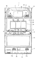
スロットマシン1は、図1(正面図)及び図2(内部構造図)に示すように、遊技者に面する側にいわゆるフロントマスク2が形成された前扉3が略矩形状の箱体である筐体15の開口部に対し図示しない蝶番機構により開閉可能に取り付けられている。フロントマスク2は、上から上パネル部2a、中パネル部2b、下パネル部2cに概ね分けられ、これらは化粧板として視覚効果を高めてデザインされた硬質プラスチックにより一体的に形成されている。また、下パネル部2cの下方には、メダルを貯留するための受け皿4aを備える受皿ユニット4が設けられている。
As shown in FIG. 1 (front view) and FIG. 2 (internal structure diagram), the slot machine 1 has a substantially rectangular box with a
上パネル部2aには、高輝度の発光ダイオード(LED)を内蔵した上部ランプ5a及びコーナーランプ5b、5c等の効果ランプが配置され、リーチや大当たり等の際に点灯または点滅して遊技者の視覚に訴える演出を行っている。また、上パネル部2aの左右位置には、それぞれスピーカを内蔵した放音部6a、6bが設けられ、効果音や楽音等によるゲームの演出を行っている。更に、各放音部6a、6bに挟まれる中央位置には、液晶表示ユニット7が配設されている。
The
なお、液晶表示ユニット7は、ゲームの進行に応じて適宜選択される動画像を表示して当該ゲームにストーリー性を与えたり、また、ボーナスゲーム等の大当たりの際には、よりダイナミックな画像が表示されて、遊技者に高配当の期待感を引き起こしたりする等の演出を行っている。 The liquid crystal display unit 7 displays a moving image that is appropriately selected according to the progress of the game to give the game a story, and when a bonus game or the like is won, a more dynamic image is displayed. It is displayed and effects such as causing a player to expect a high payout.
中段の中パネル部2bには、その中央に略長方形の透明な表示窓8aが形成されたパネル板としての中パネル板8が取り付けられている。そして、この表示窓8aを通して、筐体15内に設けられている円筒状の3個のリール10a,10b,10cを遊技者が目視できるように構成されている。
A
なお、各リール10a,10b,10cの周面には、複数の異なる種類を含む例えば21個の図柄がほぼ等間隔で配列され、表示窓8aに臨む縦3個、横3列の図柄が当該表示窓を通して遊技者に視認されるようになっている。
For example, 21 symbols including a plurality of different types are arranged at substantially equal intervals on the peripheral surfaces of the
また、図示はしていないが中パネル板8の前面適宜の位置には、内部当選した役を告知する告知表示部やクレジット数等を表示する数値表示部等の遊技情報を表示するための表示部が形成されている。
In addition, although not shown, a display for displaying game information such as a notification display section for notifying an internal winning combination and a numerical display section for displaying the number of credits, etc. is displayed at an appropriate position on the front surface of the
中パネル板8の下方には、前方に若干突出した操作卓9と呼ばれる卓状部が形成され、ここには、ゲームに使用するメダルを投入するための投入口を有するメダル投入部11と、ゲームの操作を指示するためのベットボタン12、スタートレバー13、及び3個のストップボタン14a,14b,14c等が配設されている。
Below the
ベットボタン12は、ゲームに賭けるメダルの枚数を提示するための押圧式のボタンスイッチである。スタートレバー13は、リール10a,10b,10cを一斉に回転させる指示をするためのレバースイッチであり、先端に球形の操作ノブを有するレバーを上下左右の何れかの方向に傾動操作するとオン作動し、レバーから手が離されるとスプリングの付勢力によって自動的に元の位置に戻ってオフ作動するように構成されている。
The
ストップボタン14a,14b,14cは、各リール10a,10b,10cの回転停止を個別に指示するための押圧式のボタンスイッチであり、各リールの配列に対応してそれぞれ並設されている。
The
フロントマスク2の下パネル部2cには、スロットマシン1のモデルタイプ等を遊技者へ認識させるための、例えば登場キャラクターの絵柄(図示略)などが印刷されて表示されている。
On the
前扉3の最下部に設けられた受皿ユニット4には、入賞配当等によりメダルを払い出すメダル払出口16と、スピーカを内蔵しゲームの進行に応じて演出効果音を発生させる放音部17a,17bとがそれぞれ配設されている。
The saucer unit 4 provided at the lowermost part of the
かかる構造のスロットマシン1は、先のゲームにおいて入賞しメダルの払い出しが完了した時、または先のゲームにおいてハズレが確定すると待機状態となる。この状態において、遊技者がメダル投入部11よりメダルを投入すると、そのメダルがクレジットに加算され内部貯留される。
The slot machine 1 having such a structure enters a standby state when winning in the previous game and the payout of medals are completed, or when a loss is confirmed in the previous game. In this state, when the player inserts a medal from the
この状態で遊技者がベットボタン12を押圧操作することで、クレジットされたメダルの一部が当該ゲームに賭けられゲームが開始する。そして、遊技者がスタートレバー13を傾動操作すると、全てのリール10a,10b,10cが一斉に回転し、これと同時に入賞役が内部的な処理で乱数抽選される。
When the player presses the
次に、遊技者がストップボタン14a,14b,14cを任意の順番で押圧操作すると、それに従い順次対応するリールが停止し、全てのリール10a,10b,10cが停止した後、各リールに表示された図柄の組合せと上述の内部抽選した入賞役に係る図柄の組合せとが一致しているか否かが判定される。これらが一致したときには当該入賞が確定し、その入賞役の種類に応じた枚数のメダルがクレジットに加算され配当される。入賞の配当によりクレジットの上限を超える場合には、その超過した枚数分のメダルがメダル排出口16より受皿ユニット4へ払い出される。
Next, when the player presses the
このように、スロットマシン1の遊技者は、リール10a,10b,10cを回転・停止させる遊技操作を行って、表示窓8aに変動表示した図柄が揃わなければ賭けたメダルを失うが、予め定められた組合せで図柄が揃い入賞が成立すると賭けた枚数以上のメダルを獲得し得るので、技量と運とによりメダルを増やすという興趣を伴った勝敗ゲームを楽しむことができる。
As described above, the player of the slot machine 1 performs a game operation for rotating and stopping the
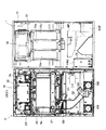
次に、フロントパネル2の裏面側について説明する。フロントパネル2の裏面側の上部には、前述した放音部6a,6bのスピーカSR,SLが設けられ、スピーカSR,SLの間には演出表示装置19が設けられている。演出表示装置19の裏側には、電気回路基板で形成された画像処理基板31及びサブ制御基板33を段状に収容した基板ケース30が取り付けられている。基板ケース30の詳細は後述する。
Next, the back side of the
画像処理基板31は、VDP(Video Display Processor)及びフレームメモリやビデオRAM等を搭載しており、液晶表示ユニット7に表示する画像データに基づいてビデオ信号を生成し、液晶表示ユニット7において演出用の動画像を表示する制御を行う。サブ制御基板33は、上部ランプ5a及びコーナランプ5b、5c等の光源であるLED等を点灯または点滅制御し、音源データを選択して復号化(再生)した音信号に基づいてスピーカ6a、6b、17a、17bを鳴動駆動し、演出画像データを適宜選択して処理する機能を有する。
The
演出表示装置19の下方には、前述した表示窓8aを形成した略長方形状の枠部材20が取り付けられており、この枠部材20の下方には、メダル投入部11より投入された投入物が正規の遊技メダルか否かを判別して振り分けるセレクト機構G0と、セレクト機構G0で振り分けられた遊技メダルを筐体15側に設けられたホッパ装置HPへ案内するガイド部材G1と、セレクト機構G0で振り分けられた異物をメダル払出口16へ案内するガイド部材G2と、ホッパ装置HPから出力される払い出し用のメダルをメダル払出口16へ案内するガイド部材G3とが設けられている。メダル払出口16の近傍には、前述した放音部17a,17bを構成するスピーカSWが取り付けられている。
Below the
枠部材20とセレクト機構G0との間には、長尺状の電気回路基板で形成された中央表示基板21が取り付けられている。この中央表示基板21には、前述した操作卓9に設けられているベットボタン12と、スタートレバー13と、ストップボタン14a,14b,14c等が電気的に配線接続され、これらのボタン12,14a,14b,14cの出力信号はハーネスを介して筐体15に設けられた主制御基板35に転送されるようになっている。
Between the
筐体15内には、主電源装置PWUと、ホッパ装置HPから溢れた遊技メダルを収容する補助貯留部SHPが設けられる他、前述したリール10a,10b,10cが設けられている。主電源装置PWUの側面には電源装置基板36が取り付けられ、リール10a,10b,10cの上方には回胴装置基板37が取り付けられ、回胴装置基板37の上方には前述した主制御基板35が取り付けられている。主制御基板35は、半導体メモリ(ROM)とマイクロプロセッサ(MPU)等が搭載されており、このマイクロプロセッサMPUが、半導体メモリROMに予め記憶されているシステムプログラムとスロットマシンゲーム用のプログラムを実行し、電源装置基板36、回胴装置基板37及びサブ制御基板33に所定の指令を行って夫々に分散制御を行わせることにより、本スロットマシン1全体を集中制御する。
The
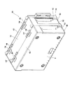
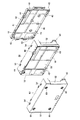
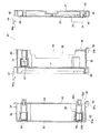
このように構成されたスロットマシン1の演出表示装置19の裏側に配設された基板ケース30は、ねじ等によって演出表示装置19の裏面側に着脱可能に取り付けられている。基板ケース30は、図3(斜視図)、図4(分解斜視図)及び図5(断面図)に示すように、透明な合成樹脂材料(例えば、PC)で一体成形され、演出表示装置19の裏面側に取り付けられるケース基部40と、ケース基部40に装着される第1ケース蓋部50と、第1ケース蓋部50に装着される第2ケース蓋部60とを備えてなる。
The
ケース基部40は、画像処理基板31を搭載して固定する長方形状のベース部41に、ベース部41の外周を囲むように立設された周壁部42を形成し、前側に開口部43を形成して、略矩形箱状に形成されている。上側に配置された周壁部42には、横方向に所定間隔を有して配置されて前側へ突出する係止部44が一対設けられている。係止部44の先端部には内側に突出する係止突起部44aが形成されている。係止部44は弾性変形可能であり、先端部を外側方向へ押圧すると、係止突起部44aが外側方向へ移動して後述する係合凸部54との係止状態を解除することができる。下側に配置された周壁部42には、横方向に所定間隔を有して配置されて周壁部42に沿って延びる支持軸部45が一対形成されている。ケース基部40の開口部43には、画像処理基板31に取り付けられた電子部品32がケース基部40の前側へ延びるように配置されて、画像処理基板31がケース基部40にねじ34等によって取り付けられている。
The
第1ケース蓋部50は、ケース基部40に取り付けられた画像処理基板31を覆うようにして配置され、画像処理基板31に面する第1天板部51にこの外周を囲むように立設された蓋側周壁部52を形成し、後側に開口部53を形成して、略矩形箱状に形成されている。上側に配置された蓋側周壁部52の外側先端部には、前述したケース基部40に設けられた係止部44の係止突起部44aを係止する係合凸部54が横方向に所定間隔を有して一対設けられている。係合凸部54は、ケース基部40に第1ケース蓋部50が装着されると、ケース基部40の対応する係止部44の係止突起部44aと係止可能な位置に配設されている。また上側に配置された蓋側周壁部52の外側前端部には、横方向に所定間隔を有して配置されて前側へ延びる係止部44'が一対設けられている。この係止部44'は、前述したケース基部40に設けられた係止部44と同一形状を有しているので、係止部44に準じた符号を附してその説明を省略する。
The
下側に配置された蓋側周壁部52の外側後端部には、第1ケース蓋部50の支持軸部45に着脱可能であって回動自在に嵌合する嵌合凹部55が横方向に所定間隔を有して一対設けられている。この嵌合凹部55は略円形状であり、下側に支持軸部45を挿抜可能な開口部55aが形成されている。このため、支持軸部45をこの開口部55aから嵌合凹部55内に挿着し、また嵌合凹部55から支持軸部45を抜脱することができ、その結果、第1ケース蓋部50をケース基部40に着脱可能に装着することができる。また下側に配置された蓋側周壁部52の外側前端部には、前述したケース基部40に設けられた支持軸部45と同一形状の支持軸部45'が横方向に所定間隔を有して一対設けられている。
A
ケース基部40に第1ケース蓋部50を装着すると、第1ケース蓋部50の第1天板部51及び蓋側周壁部52によって囲まれる空間部56によってケース基部40に取り付けられた画像処理基板31を収容することができる。
When the
第1ケース蓋部50内には、前後方向に延びる封鎖手段57が複数設けられており、これらの封鎖手段57によってケース基部40に第1ケース蓋部50が固定されると、封鎖手段57を壊さなければケース基部40と第1ケース蓋部50を分離することができない。
A plurality of sealing means 57 extending in the front-rear direction are provided in the
第2ケース蓋部60は、第1ケース蓋部50の第1天板部51を覆うようにして配置され、第1天板部51に面する第2天板部61にこの外周を囲むように立設された蓋側周壁部62を形成し、後側に開口部63を形成して、略矩形箱状に形成されている。上側に配置された蓋側周壁部62の外側後端部には、前述した第1ケース蓋部50に設けられた係止部44'の係止突起部44'aを係止する係合凸部54'が横方向に所定間隔を有して一対設けられている。係合凸部54'は、第1ケース蓋部50に第2ケース蓋部60が装着されると、第1ケース蓋部50の対応する係止部44'の係止突起部44'aを係止可能な位置に配置されている。また下側に配置された蓋側周壁部62の外側後端部には、第1ケース蓋部50の支持軸部45'に着脱可能であって回動自在に嵌合する嵌合凹部55'が横方向に所定間隔を有して一対設けられている。この嵌合凹部55'は、第1ケース蓋部50に設けられた嵌合凹部55と同一形状であるので、嵌合凹部55に準じた符号を附してその説明を省略する。
The second
第2ケース蓋部60は、第2天板部61及び蓋側周壁部62によって囲まれる空間部64を形成し、この空間部64内に第2天板部61から後側に延びる封鎖手段65が複数設けられている。封鎖手段65は、第2天板部61から後側に延びる筒部65aと、筒部65aの開口部に嵌着されるキャップ部65bと、筒部65a内に挿入されるねじ65cと、サブ制御基板33に取り付けられてねじ65cを留めるボス部65dとを有してなる。この封鎖手段65の筒部65aの先端部にサブ制御基板33を配置し、筒部65a内に挿入されたねじ65cをボス部65dに螺合し、開口部にキャップ部65bを嵌着することで、サブ制御基板33は封鎖手段65を介して第2ケース蓋部60に固定される。サブ制御基板33は、それに取り付けられた電子部品38が第2天板部61側に向いた状態で固定されている。このため、第2天板部61の外側から第2天板部61を介してサブ制御基板33の電子部品38の目視確認が可能であり、また封鎖手段65を壊さなければこの電子部品38に触れることができない。
The second
つまり、基板ケース30は、ケース基部40に第1ケース蓋部50を装着して形成される第1ケース内部に画像処理基板31を収容し、封鎖手段57によって第1ケース蓋部50とケース基部40とを分離不能に固定し、サブ制御基板33を封鎖手段65によって第2ケース蓋部60に分離不能に固定し、第2ケース蓋部60を第1ケース蓋部50に回動自在に取り付けて構成されている。
That is, the
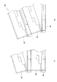
このため、基板ケース30の外側から第2ケース蓋部60内に収容されたサブ制御基板33の電子部品38を目視確認することができる。また第1ケース蓋部50内に収容された画像処理基板31の電子部品32を目視確認する場合、図6(b)(部分側面図)及び図5に示すように、第1ケース蓋部50とケース基部40が封鎖手段57によって固定されていなければ、ケース基部40に対して第1ケース蓋部50を回動させると、画像処理基板31が露出してこれに取り付けられた電子部品32を目視確認することができるが、通常は、封鎖手段57によって第1ケース蓋部50とケース基部40は固定されているため、画像処理基板31の電子部品32を目視確認することができない。
For this reason, the
しかしながら、図6(a)(部分側面図)及び図5に示すように、に示すように、第2ケース蓋部60は第1ケース蓋部50に対して回動自在に取り付けられているので、第1ケース蓋部50に対して第2ケース蓋部60を回動させるだけで、第1ケース蓋部50の第1天板部51が露出して、この第1天板部51を介して第1ケース蓋部50内に収容された画像処理基板31の電子部品32を目視確認することができる。このとき第2ケース蓋部60内に収容されたサブ制御基板33も回動するが、サブ制御基板33に取り付けられた電子部品38は内側に向いて取り付けられているので、電子部品38が露出することはない。またサブ制御基板33は封鎖手段65によって第2ケース蓋部60に固定されているので、この封鎖手段65を壊さなければサブ制御基板33の電子部品38に触れることはできない。このため、この電子部品38に対する不正操作を高い抑止力で防止することができる。
However, as shown in FIG. 6A (partial side view) and FIG. 5, the
このように、基板ケース30は、第2ケース蓋部60を第1ケース蓋部50に対して回動させるだけで、サブ制御基板33が第1ケース蓋部50から離反するので、サブ制御基板33を第2ケース蓋部60から取り外す必要がない。このため、本発明の基板ケース30は、第1ケース蓋部50に収容された画像処理基板31の電子部品32の目視確認を容易に行うことができる。従って、第1ケース蓋部50に目視確認の必要性がある電子部品を取り付けた回路基板を積極的に収容することができ、本発明の基板ケース30はスロットマシン1内における回路基板の配置の自由を拡大することができる。
Thus, since the
なお、前述した実施例では、画像処理基板31の電子部品32を目視確認する際に、第2ケース蓋部60を第1ケース蓋部50に対して回動させる場合を示したが、第2ケース蓋部60を第1ケース蓋部50から取り外してもよい。このようにすると、第1ケース蓋部50の第1天板部51を確実に露出することができ、電子部品の目視確認の作業性をより向上することができる。
In the above-described embodiment, the case where the
また前述した実施例では、基板ケース30を透明な材料で形成したが、電子部品の目視が可能であれば、基板ケース30を色付き又は無色の半透明な材料で形成してもよい。
In the above-described embodiment, the
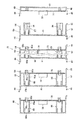
また前述した基板ケース30は、ケース基部40に第1ケース蓋部50及び第2ケース蓋部60を2段状に重ねたものを示したが、図7(断面図)に示すように、ケース基部40に第1ケース蓋部50を複数段重ね、これらの先端部に第2ケース蓋部60を重ねるようにして多段状の基板ケース70を構成してもよい。なお、この多段状の基板ケース70を構成するケース基部40、第1ケース蓋部50、第2ケース蓋部60は、2段状の基板ケース30のそれらと同様の構成であるので、同一態様部分については同一符号を附してその説明を省略する。
In addition, the
このように多段状の基板ケース70を構成すると、ケース基部40に取り付けられた回路基板71の電子部品72を目視確認する場合には、ケース基部40側から2段目の第1ケース蓋部50を回動させる。また2段目の第1ケース蓋部50内の回路基板73の電子部品74を目視確認する場合には、ケース基部40側から3段目の第1ケース蓋部50を回動させればよい。このようにケース基部40に取り付けられた回路基板71の電子部品72のみならず、第1ケース蓋部50に取り付けられた回路基板73の電子部品74の目視確認を容易に行うことができ、遊技機内の回路基板の配置の自由をさらに拡大することができる。
When the
さらに前述した実施例では、スロットマシン1を例にしたが、パチンコやゲームセンタで用いられているゲーム機などを対象にしてもよい。 Furthermore, in the above-described embodiment, the slot machine 1 is taken as an example, but a game machine or the like used in a pachinko or game center may be targeted.
1 スロットマシン(遊技機)
30 基板ケース
31 画像処理基板(第1回路基板)
33 サブ制御基板(第2回路基板)
38 電子部品
40 ケース基部
50 第1ケース蓋部
60 第2ケース蓋部
61 第2天板部(天板部)
65 封鎖手段
1 slot machine (game machine)
30
33 Sub-control board (second circuit board)
38
65 Blocking means
Claims (3)
前記第2ケース蓋部は、前記第1ケース蓋部に着脱自在に装着され、
前記第2回路基板は、該第2回路基板に取り付けられた電子部品が前記第2ケース蓋部の天板部の内面に面するように前記第2ケース蓋部の内側に配置されて該第2ケース蓋部に取り付けられることを特徴とする遊技機の基板ケース。 A case base attached to the gaming machine, a first case lid attached to the case base and formed of a transparent material, and a second case lid attached to the first case lid, A first circuit board for controlling the operation of the gaming machine is accommodated in a first case formed by attaching the first case lid to the case base, and the second case lid is placed in the first case lid. A board case for a gaming machine that houses a second circuit board inside a second case formed by attaching
The second case lid is detachably attached to the first case lid,
The second circuit board is disposed on the inner side of the second case lid so that the electronic component attached to the second circuit board faces the inner surface of the top plate of the second case lid. A board case for a gaming machine, which is attached to a two-case lid.
Priority Applications (1)
| Application Number | Priority Date | Filing Date | Title |
|---|---|---|---|
| JP2006072198A JP2007244635A (en) | 2006-03-16 | 2006-03-16 | Board case for game machine |
Applications Claiming Priority (1)
| Application Number | Priority Date | Filing Date | Title |
|---|---|---|---|
| JP2006072198A JP2007244635A (en) | 2006-03-16 | 2006-03-16 | Board case for game machine |
Publications (1)
| Publication Number | Publication Date |
|---|---|
| JP2007244635A true JP2007244635A (en) | 2007-09-27 |
Family
ID=38589545
Family Applications (1)
| Application Number | Title | Priority Date | Filing Date |
|---|---|---|---|
| JP2006072198A Pending JP2007244635A (en) | 2006-03-16 | 2006-03-16 | Board case for game machine |
Country Status (1)
| Country | Link |
|---|---|
| JP (1) | JP2007244635A (en) |
Citations (3)
| Publication number | Priority date | Publication date | Assignee | Title |
|---|---|---|---|---|
| JP2001054667A (en) * | 1999-08-17 | 2001-02-27 | Sophia Co Ltd | Game machine |
| JP2004215838A (en) * | 2003-01-14 | 2004-08-05 | Samii Kk | Controller of game machine |
| JP2005305133A (en) * | 2004-03-24 | 2005-11-04 | Daiichi Shokai Co Ltd | Game machine |
-
2006
- 2006-03-16 JP JP2006072198A patent/JP2007244635A/en active Pending
Patent Citations (3)
| Publication number | Priority date | Publication date | Assignee | Title |
|---|---|---|---|---|
| JP2001054667A (en) * | 1999-08-17 | 2001-02-27 | Sophia Co Ltd | Game machine |
| JP2004215838A (en) * | 2003-01-14 | 2004-08-05 | Samii Kk | Controller of game machine |
| JP2005305133A (en) * | 2004-03-24 | 2005-11-04 | Daiichi Shokai Co Ltd | Game machine |
Similar Documents
| Publication | Publication Date | Title |
|---|---|---|
| JP4986015B2 (en) | Game control board assembly sealing structure and gaming machine | |
| JP2007307003A (en) | Game machine | |
| JP4942986B2 (en) | Display lighting device for gaming machine | |
| JP2005102802A (en) | Reel device and reel type game machine mounted with the same | |
| JP2005065969A (en) | Top panel part structure and game machine | |
| JP2008295655A (en) | Segment display device and game machine | |
| JP2005124736A (en) | Rotary drum type game machine | |
| JP2007244635A (en) | Board case for game machine | |
| JP5242989B2 (en) | Game machine | |
| JP5632502B2 (en) | Game machine | |
| JP4974271B2 (en) | Light-emitting diode mounting base | |
| JP2005124732A (en) | Rotary drum device and rotary drum type game machine loaded with the same | |
| JP6695643B2 (en) | Amusement machine | |
| JP5832603B2 (en) | Game machine | |
| JP2008237347A (en) | Game machine | |
| JP5077988B2 (en) | Game machine | |
| JP2007252395A (en) | Drum type game machine | |
| JP2005304834A (en) | Game machine | |
| JP2005323771A (en) | Game machine | |
| JP2007236798A (en) | Rotary-drum type game machine | |
| JP2005095207A (en) | Game machine | |
| JP2007252487A (en) | Game machine | |
| JP2005177353A (en) | Game machine | |
| JP2005124734A (en) | Rotary drum type game machine | |
| JP2007082705A (en) | Rotary drum type game machine |
Legal Events
| Date | Code | Title | Description |
|---|---|---|---|
| A621 | Written request for application examination |
Free format text: JAPANESE INTERMEDIATE CODE: A621 Effective date: 20081118 |
|
| RD02 | Notification of acceptance of power of attorney |
Free format text: JAPANESE INTERMEDIATE CODE: A7422 Effective date: 20100705 |
|
| RD04 | Notification of resignation of power of attorney |
Free format text: JAPANESE INTERMEDIATE CODE: A7424 Effective date: 20100713 |
|
| A131 | Notification of reasons for refusal |
Free format text: JAPANESE INTERMEDIATE CODE: A131 Effective date: 20110107 |
|
| A977 | Report on retrieval |
Free format text: JAPANESE INTERMEDIATE CODE: A971007 Effective date: 20110113 |
|
| A02 | Decision of refusal |
Free format text: JAPANESE INTERMEDIATE CODE: A02 Effective date: 20120106 |