JP2007239642A - Valve timing adjusting device - Google Patents
Valve timing adjusting device Download PDFInfo
- Publication number
- JP2007239642A JP2007239642A JP2006064100A JP2006064100A JP2007239642A JP 2007239642 A JP2007239642 A JP 2007239642A JP 2006064100 A JP2006064100 A JP 2006064100A JP 2006064100 A JP2006064100 A JP 2006064100A JP 2007239642 A JP2007239642 A JP 2007239642A
- Authority
- JP
- Japan
- Prior art keywords
- rotating body
- gear portion
- internal gear
- valve timing
- planetary
- Prior art date
- Legal status (The legal status is an assumption and is not a legal conclusion. Google has not performed a legal analysis and makes no representation as to the accuracy of the status listed.)
- Withdrawn
Links
- 230000002093 peripheral effect Effects 0.000 claims abstract description 43
- 239000012530 fluid Substances 0.000 claims abstract description 19
- 230000001050 lubricating effect Effects 0.000 claims abstract description 19
- 230000033001 locomotion Effects 0.000 claims abstract description 18
- 238000002485 combustion reaction Methods 0.000 claims description 31
- 230000005540 biological transmission Effects 0.000 claims description 3
- 238000007599 discharging Methods 0.000 abstract description 4
- 239000010687 lubricating oil Substances 0.000 description 34
- 230000007246 mechanism Effects 0.000 description 23
- 230000004048 modification Effects 0.000 description 8
- 238000012986 modification Methods 0.000 description 8
- 230000007257 malfunction Effects 0.000 description 7
- 230000008859 change Effects 0.000 description 6
- 230000000694 effects Effects 0.000 description 6
- 230000000149 penetrating effect Effects 0.000 description 2
- 239000000843 powder Substances 0.000 description 2
- 239000002699 waste material Substances 0.000 description 2
- 230000009471 action Effects 0.000 description 1
- 238000013459 approach Methods 0.000 description 1
- 230000015572 biosynthetic process Effects 0.000 description 1
- 238000006073 displacement reaction Methods 0.000 description 1
- 230000005484 gravity Effects 0.000 description 1
- 230000012447 hatching Effects 0.000 description 1
- 238000005461 lubrication Methods 0.000 description 1
- 230000013011 mating Effects 0.000 description 1
- 230000009467 reduction Effects 0.000 description 1
- 230000001105 regulatory effect Effects 0.000 description 1
- 230000004044 response Effects 0.000 description 1
Images


Landscapes
- Valve Device For Special Equipments (AREA)
Abstract
Description
本発明は、クランク軸からのトルク伝達によりカム軸が開閉する吸気弁及び排気弁のうち少なくとも一方のバルブタイミングを調整する内燃機関のバルブタイミング調整装置に関する。 The present invention relates to a valve timing adjusting device for an internal combustion engine that adjusts the valve timing of at least one of an intake valve and an exhaust valve whose camshaft opens and closes by torque transmission from a crankshaft.
従来、クランク軸及びカム軸にそれぞれ連動して回転する二つの回転体間の相対回転位相を変化させることにより、バルブタイミングを調整するバルブタイミング調整装置が知られている。例えば特許文献1には、遊星歯車を主体とする差動歯車機構により二つの回転体間の相対回転位相を変化させるバルブタイミング調整装置が開示されている。 2. Description of the Related Art Conventionally, there is known a valve timing adjusting device that adjusts a valve timing by changing a relative rotational phase between two rotating bodies that rotate in conjunction with a crankshaft and a camshaft. For example, Patent Document 1 discloses a valve timing adjusting device that changes a relative rotational phase between two rotating bodies by a differential gear mechanism mainly including a planetary gear.
さて、特許文献1に開示されるように差動歯車機構を用いる場合、内燃機関の運転状態に追従する当該機構の作動頻度は極めて高くなることから、歯車の噛合部分等では磨耗が生じ易い。そこで、特許文献1に開示される装置では、内部へ潤滑油を導入して歯車の噛合部分等を潤滑しつつ、潤滑により汚れた潤滑油を排出孔から排出するようにしている。 Now, when a differential gear mechanism is used as disclosed in Patent Document 1, since the operating frequency of the mechanism that follows the operating state of the internal combustion engine becomes extremely high, wear easily occurs at the meshing portion of the gear. Therefore, in the apparatus disclosed in Patent Document 1, lubricating oil is introduced into the interior to lubricate the meshing portion of the gear and the like, and the lubricating oil contaminated by lubrication is discharged from the discharge hole.
しかし、特許文献1に開示される装置において排出孔は、クランク軸に連動して回転する回転体を軸方向へ貫通して当該軸方向へ潤滑油を案内するものであるため、回転体の回転により遠心力が作用する潤滑油は、排出孔へは流入し難く、また流動抵抗によって排出孔内部を流れ難くなる。故に、潤滑油の排出効率が低下し、磨耗粉等の異物を含んだ潤滑油が装置内部に滞留し易くなるため、そうした異物が差動歯車機構の歯車間等に噛み込まれて作動不良や破損を招くおそれがあった。
本発明は、このような問題に鑑みてなされたものであって、その目的は、作動不良及び破損を防止するバルブタイミング調整装置を提供することにある。
However, in the apparatus disclosed in Patent Document 1, the discharge hole penetrates the rotating body that rotates in conjunction with the crankshaft in the axial direction and guides the lubricating oil in the axial direction. Therefore, the lubricating oil on which the centrifugal force acts is unlikely to flow into the discharge hole and is difficult to flow through the discharge hole due to the flow resistance. Therefore, the efficiency of lubricating oil discharge is reduced, and lubricating oil containing foreign matter such as wear powder tends to stay inside the device, so that such foreign matter is caught between the gears of the differential gear mechanism and the like. There was a risk of damage.
The present invention has been made in view of such problems, and an object of the present invention is to provide a valve timing adjusting device that prevents malfunction and breakage.
請求項1に記載の発明によると、クランク軸及びカム軸にそれぞれ連動して回転する第一回転体及び第二回転体のうち、内歯車部が設けられる特定回転体は、その内部へ導入された潤滑流体を排出する排出孔を有する。ここで排出孔は、特定回転体内部の潤滑流体を内歯車部の歯底から案内して排出するものであるので、特定回転体の回転による遠心力や、内歯車部の排出孔近傍の歯に噛合しようとする遊星歯車の歯の押出力によって潤滑油が流入し易い。しかも排出孔は、潤滑流体を特定回転体の外周側へ案内して排出するものであるので、遠心力が作用する潤滑流体であっても、小さな流動抵抗にて流すことができる。このような請求項1に記載の発明によれば、潤滑流体の排出効率が高くなるので、遊星歯車及び内歯車部間等に潤滑流体中の異物が噛み込まれて作動不良や破損を招く事態を防止することができる。 According to the first aspect of the present invention, the specific rotating body provided with the internal gear portion is introduced into the first rotating body and the second rotating body that rotate in conjunction with the crankshaft and the camshaft, respectively. And a discharge hole for discharging the lubricating fluid. Here, the discharge hole guides and discharges the lubricating fluid inside the specific rotating body from the tooth bottom of the internal gear portion, so that the centrifugal force due to the rotation of the specific rotating body and the teeth near the discharge hole of the internal gear portion are discharged. Lubricating oil tends to flow in due to the pushing force of the teeth of the planetary gear trying to mesh with the gear. In addition, since the discharge hole guides and discharges the lubricating fluid to the outer peripheral side of the specific rotating body, even the lubricating fluid on which centrifugal force acts can flow with a small flow resistance. According to the first aspect of the present invention, since the lubricating fluid discharge efficiency is increased, foreign matter in the lubricating fluid is caught between the planetary gear and the internal gear portion, etc., resulting in malfunction or damage. Can be prevented.
請求項2に記載の発明によると、排出孔は、特定回転体の回転方向に複数設けられるので、潤滑流体の排出効率をさらに高めることができる。
内燃機関の運転と共に特定回転体の内部へ導入された潤滑流体は、内燃機関の停止後に低温環境下に晒されると、その粘度が増大する。この場合、内燃機関の始動時には、粘度の増大した潤滑流体が遊星歯車や内歯車部等へ大きな回転抵抗を及ぼすようになり、装置の作動に必要なエネルギーが無駄に増大する。そこで請求項3に記載の発明では、特定回転体の軸方向を水平方向と実質的に一致させるので、内燃機関の停止後において特定回転体内部の潤滑流体は、特定回転体の回転方向に設けられる複数の排出孔のうち少なくとも一つの内部を、重力作用によって特定回転体の外周側まで案内され得る。故に内燃機関の停止後には、特定回転体内部の潤滑流体を減らした状態にて、内燃機関の始動に備えることができる。したがって、低温環境下における内燃機関の始動時であっても、粘度増大した潤滑流体により遊星歯車や内歯車部等が受ける回転抵抗を低減して、エネルギーの浪費を抑えることができる。
According to the second aspect of the present invention, since the plurality of discharge holes are provided in the rotation direction of the specific rotating body, the discharge efficiency of the lubricating fluid can be further increased.
When the lubricating fluid introduced into the specific rotating body along with the operation of the internal combustion engine is exposed to a low temperature environment after the internal combustion engine is stopped, its viscosity increases. In this case, when the internal combustion engine is started, the lubricating fluid having increased viscosity exerts a large rotational resistance on the planetary gear, the internal gear portion, and the like, and energy necessary for the operation of the apparatus is unnecessarily increased. Therefore, in the invention described in claim 3, since the axial direction of the specific rotating body is substantially matched with the horizontal direction, the lubricating fluid inside the specific rotating body is provided in the rotating direction of the specific rotating body after the internal combustion engine is stopped. The inside of at least one of the plurality of discharge holes formed can be guided to the outer peripheral side of the specific rotating body by a gravitational action. Therefore, after the internal combustion engine is stopped, it is possible to prepare for the start of the internal combustion engine in a state where the lubricating fluid inside the specific rotating body is reduced. Therefore, even when the internal combustion engine is started in a low-temperature environment, it is possible to reduce the rotational resistance received by the planetary gear, the internal gear portion, and the like by the lubricating fluid whose viscosity has been increased, thereby suppressing waste of energy.
請求項4に記載の発明によると、少なくとも一つの排出孔は特定回転体を径方向へ貫通する。これにより、排出孔の形成が容易となるばかりでなく、排出孔内部での潤滑流体の流動抵抗が低減されて潤滑流体の排出効率が高められる。
尚、排出孔については、潤滑流体を内歯車部の歯底から特定回転体の外周側へ案内可能なものであればよく、請求項4に記載の形態以外にも、例えば特定回転体の回転軸線に対して傾斜するものであってもよい。
According to the invention of
In addition, about the discharge hole, what is necessary is just to be able to guide the lubricating fluid from the tooth bottom of the internal gear portion to the outer peripheral side of the specific rotating body. It may be inclined with respect to the axis.
請求項5に記載の発明によると、遊星歯車は、第一外歯車部及び第二外歯車部をそれぞれ第一内歯車部及び第二内歯車部に噛合させつつ一体に遊星運動させることにより、第一回転体及び第二回転体間の相対回転位相を変化させる。このような構成によれば、各歯車部を小径に形成して体格の小型化を図りつつ、大きな減速比を得ることができる。しかも、第一内歯車部及び第二内歯車部のうち請求項1〜4のいずれか一項に記載の内歯車部である少なくとも一方が設けられた特定回転体は、請求項1〜4のいずれか一項に記載の排出孔を有するので、作動不良及び破損の防止効果を発揮することもできる。
According to the invention described in
尚、請求項6に記載の発明の如く、第一回転体及び第二回転体のうち特定回転体である一方の内歯車部に噛合する遊星歯車が、第一回転体及び第二回転体のうち自身に連繋する他方を自身の遊星運動に伴って回転駆動することにより相対回転位相を変化させる構成を採用してもよい。因みにこの構成によると、第一回転体及び第二回転体のうち請求項1〜4のいずれか一項に記載の内歯車部が設けられた特定回転体が請求項1〜4のいずれか一項に記載の排出孔を有するので、作動不良及び破損の防止効果を発揮することができる。また、この構成において、第一回転体及び第二回転体のうち特定回転体ではない上記他方の回転体は、例えば係合等により遊星歯車に直接連繋するものであってもよいし、例えば機構等を介して間接的に遊星歯車に連繋するものであってもよい。 As in the sixth aspect of the invention, the planetary gear meshing with one of the first rotating body and the second rotating body, which is the specific rotating body, is formed of the first rotating body and the second rotating body. You may employ | adopt the structure which changes a relative rotational phase by rotationally driving the other connected to self with own planetary motion. Incidentally, according to this structure, the specific rotary body in which the internal gear part as described in any one of Claims 1-4 is provided among the 1st rotary body and the 2nd rotary body is any one of Claims 1-4. Since the discharge hole described in the item is provided, the effect of preventing malfunction and damage can be exhibited. In this configuration, the other rotating body that is not the specific rotating body among the first rotating body and the second rotating body may be directly connected to the planetary gear by, for example, engagement or the like. It may be linked to the planetary gear indirectly through the like.
請求項7に記載の発明によると、遊星歯車を内周側から自転自在に支持する遊星キャリヤには、電動モータの発生した回転トルクが遊星歯車の公転方向へ与えられる。この回転トルクを受けて遊星歯車は遊星運動し、第一回転体及び第二回転体の間の相対回転位相変化を生じさせるので、電動モータの回転トルク制御によって当該相対回転位相、ひいてはバルブタイミングを正確に調整することができる。そして特に、遊星運動する遊星歯車とそれに噛合する内歯車部との間では、異物の噛込による作動不良及び破損が防止された状態にあるので、バルブタイミングの正確な調整を長期に亘って実現することができる。
尚、遊星キャリヤへ与える回転トルクを発生する手段としては、電動モータ以外にも、例えば油圧モータや電磁ブレーキ装置等であってもよい。
According to the seventh aspect of the present invention, the rotational torque generated by the electric motor is applied in the revolving direction of the planetary gear to the planetary carrier that supports the planetary gear so as to rotate freely from the inner peripheral side. The planetary gear undergoes planetary motion in response to this rotational torque, causing a relative rotational phase change between the first and second rotating bodies, so that the relative rotational phase and thus the valve timing is controlled by the rotational torque control of the electric motor. It can be adjusted accurately. In particular, between the planetary gear that moves in a planetary motion and the internal gear portion that meshes with it, the malfunction and damage due to foreign object biting are prevented, so accurate adjustment of valve timing is achieved over a long period of time. can do.
The means for generating the rotational torque applied to the planetary carrier may be, for example, a hydraulic motor or an electromagnetic brake device in addition to the electric motor.
以下、本発明の複数の実施形態を図面に基づいて説明する。尚、各実施形態において対応する構成要素には同一の符号を付すことにより、重複する説明を省略する。
(第一実施形態)
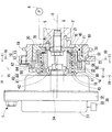
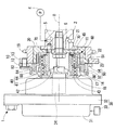
図1は、本発明の第一実施形態によるバルブタイミング調整装置1を示している。バルブタイミング調整装置1は、内燃機関のクランク軸からカム軸2へ機関トルクを伝達する伝達系に設けられている。バルブタイミング調整装置1は、クランク軸とカム軸2との間の相対回転位相を変化させることにより、内燃機関の吸気弁のバルブタイミングを調整する。尚、図1における上下方向が実際の鉛直方向と実質的に一致し、図1において回転軸線Oが延びる左右方向が実際の水平方向と実質的に一致する。
バルブタイミング調整装置1は、駆動側回転体10、従動側回転体20、制御ユニット30、遊星キャリヤ40、遊星歯車50を備えている。
Hereinafter, a plurality of embodiments of the present invention will be described with reference to the drawings. In addition, the overlapping description is abbreviate | omitted by attaching | subjecting the same code | symbol to the corresponding component in each embodiment.
(First embodiment)
FIG. 1 shows a valve timing adjusting apparatus 1 according to a first embodiment of the present invention. The valve timing adjusting device 1 is provided in a transmission system that transmits engine torque from the crankshaft of the internal combustion engine to the
The valve timing adjusting device 1 includes a driving
駆動側回転体10と従動側回転体20とは共同して、遊星キャリヤ40及び遊星歯車50等を収容する空間11を内部に形成している。
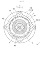
図1,2に示すように駆動側回転体10は、有底円筒状の歯車部材12と、円筒状のスプロケット13とを同軸に組み合わせて構成されている。歯車部材12の周壁部は、歯先円面が歯底円の内周側にある駆動側内歯車部14を形成している。歯車部材12は、スプロケット13に螺子留めされている。スプロケット13には、外周側へ突出する形態で複数の歯19が設けられており、これらの歯19とクランク軸の複数の歯との間で環状のタイミングチェーンが巻き掛けられる。故に、クランク軸から出力された機関トルクがタイミングチェーンを通じてスプロケット13へ入力されるときには、駆動側回転体10はクランク軸と連動して、当該クランク軸に対する相対回転位相を保ちつつ回転軸線O周りに回転する。このとき駆動側回転体10の回転方向は、図2の反時計方向となる。
The driving-
As shown in FIGS. 1 and 2, the drive-
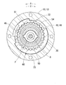
図1,3に示すように従動側回転体20は有底円筒状であり、駆動側回転体10及びカム軸2と同軸に配置されている。従動側回転体20の底部は、カム軸2の一端部にボルト固定される固定部21を形成している。このボルト固定によって従動側回転体20は、カム軸2と連動して、当該軸2に対する相対回転位相を保ちつつ回転軸線O周りに回転可能となっており、また駆動側回転体10に対して相対回転可能となっている。尚、駆動側回転体10に対して従動側回転体20が進角する相対回転方向が方向Xであり、駆動側回転体10に対して従動側回転体20が遅角する相対回転方向が方向Yである。
As shown in FIGS. 1 and 3, the driven-
従動側回転体20の周壁部は、歯先円が歯底円の内周側にある従動側内歯車部22を形成している。ここで、従動側内歯車部22の内径は駆動側内歯車部14の内径よりも小さく設定され、従動側内歯車部22の歯数は駆動側内歯車部14の歯数よりも少なく設定されている。従動側内歯車部22の外周壁はスプロケット13の内周壁に嵌合しており、それによって従動側回転体20が駆動側回転体10を内周側から相対回転自在に支持している。従動側内歯車部22の固定部21とは反対側端部には、外周側へ突出するフランジ部23が設けられている。回転軸線Oが延びる軸方向においてフランジ部23は、駆動側内歯車部14の端面とスプロケット13の端面との間に挟持されている。この挟持形態によって、従動側内歯車部22と駆動側内歯車部14とが軸方向にずれて隣接していると共に、従動側回転体20に対する駆動側回転体10の軸方向への相対変位が規制されている。
The peripheral wall portion of the driven-
図1に示すように制御ユニット30は、電動モータ32、通電制御回路33等から構成されている。電動モータ32は、回転体10,20を挟んでカム軸2とは反対側に配置されている。電動モータ32は例えばブラシレスモータ等であり、内燃機関にステー(図示しない)を介して固定されるモータケース31並びにモータケース31によって正逆回転自在に支持されるモータ軸34を有している。通電制御回路33はマイクロコンピュータ等の電気回路であり、モータケース31の外部又は内部に配置されて電動モータ32と電気的に接続されている。通電制御回路33は、電動モータ32のコイル(図示しない)への通電を内燃機関の運転状態等に応じて制御する。この通電制御によって電動モータ32は、モータ軸34の周りに回転磁界を形成し、当該回転磁界の方向に応じた方向X,Y(図4参照)の回転トルクをモータ軸34から出力する。
As shown in FIG. 1, the
図1,4に示すように、遊星キャリヤ40の入力部41は回転体10,20及び軸2,34と同軸の円筒状であり、継手42を介してモータ軸34に固定されている。この固定によって遊星キャリヤ40は、モータ軸34と連動して回転軸線O周りに回転可能となっており、また駆動側回転体10に対しては相対回転可能となっている。入力部41は、歯車部材12の底部18を軸方向へ貫通する中心孔17の内周側に配置されており、ベアリング43を介して駆動側回転体10を内周側から支持している。
As shown in FIGS. 1 and 4, the
図1,2に示すように、遊星キャリヤ40において入力部41よりも固定部21側の偏心部44は、回転体10,20及び軸2,34に対して外周壁が偏心する円筒状である。偏心部44は、遊星歯車50を軸方向へ貫通する中心孔51の内周側に配置されており、ベアリング45を介して遊星歯車50を内周側から支持している。この支持により遊星歯車50は、偏心部44の外周壁の中心軸線である偏心軸線P周りに自転可能且つ偏心部44の回転方向へ公転可能となっている。即ち遊星歯車50は、遊星運動可能に配置されている。
As shown in FIGS. 1 and 2, in the
図1〜3に示すように遊星歯車50は二段円筒状であり、歯先円が歯底円の外周側にある駆動側外歯車部52及び従動側外歯車部54をそれぞれ大径部分及び小径部分によって形成している。ここで、駆動側外歯車部52の歯数は駆動側内歯車部14の歯数よりも所定数N(ここでは一つ)少なく設定され、また従動側外歯車部54の歯数は従動側内歯車部22よりも所定数N少なく設定されている。したがって、従動側外歯車部54の歯数は駆動側外歯車部52の歯数よりも少ない。駆動側外歯車部52は駆動側内歯車部14の内周側に配置されて、当該歯車部14の一部と噛み合っている。また、駆動側外歯車部52よりも固定部21側の従動側外歯車部54は従動側内歯車部22の内周側に配置されて、当該歯車部22の一部と噛み合っている。
As shown in FIGS. 1 to 3, the
以上の構成により、回転体10,20内部の空間(以下、単に内部空間という)11には、偏心部44の外周側において駆動側内歯車部14と従動側内歯車部22とが遊星歯車50を介して連繋してなる差動歯車機構60が形成されている。そしてこの差動歯車機構60において、遊星キャリヤ40が駆動側回転体10に対して相対回転しないときには、遊星歯車50が外歯車部52,54の内歯車部14,22との噛合位置を保ちつつ回転体10,20と共に回転する。これにより回転体10,20間の相対回転位相が保持されるので、バルブタイミングも保持される。一方、電動モータ32が発生する回転トルクの方向Xへの増大等により、遊星キャリヤ40が駆動側回転体10に対して方向Xへ相対回転するときには、遊星歯車50が外歯車部52,54の内歯車部14,22との噛合位置を変化させつつ遊星運動することで、従動側回転体20が駆動側回転体10に対して方向Xへ相対回転する。したがって、バルブタイミングが進角側へ変移する。また一方、電動モータ32が発生する回転トルクの方向Yへの増大等により、遊星キャリヤ40が駆動側回転体10に対して方向Yへ相対回転するときには、遊星歯車50が外歯車部52,54の内歯車部14,22との噛合位置を変化させつつ遊星運動することで、従動側回転体20が駆動側回転体10に対して方向Yへ相対回転する。したがって、バルブタイミングが遅角側へ変移する。
With the above configuration, in the space (hereinafter simply referred to as the internal space) 11 inside the rotating
次に、バルブタイミング調整装置1の特徴部分について詳しく説明する。
図1,5に示すように従動側回転体20は、潤滑流体としての内燃機関用潤滑油を内部空間11へ導入するために導入孔70を有している。具体的に導入孔70は、従動側回転体20の固定部21において回転軸線Oに関して対称となる二箇所に設けられている。各導入孔70の出口部は従動側内歯車部22と偏心部44との間へ向かって開口し、内部空間11と連通している。各導入孔70の入口部はカム軸2へ向かって開口しており、カム軸2において内燃機関用のポンプ4から潤滑油が供給される二つの供給孔5のうち対応するものと連通している。
Next, the characteristic part of the valve timing adjusting device 1 will be described in detail.
As shown in FIGS. 1 and 5, the driven-
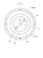
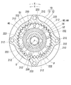
図1,6に示すように駆動側回転体10は、内部空間11から潤滑油を排出するために排出孔80を有している。具体的に排出孔80は、駆動側回転体10をなす歯車部材12の駆動側内歯車部14において回転方向に略等間隔をあけた八箇所に設けられている。各排出孔80は、駆動側内歯車部14の従動側内歯車部22とは反対側端を径方向へストレートに貫通している。各排出孔80の出口部は駆動側内歯車部14の外周側へ向かって開口し、回転体10,20の外部と連通している。各排出孔80の入口部は駆動側内歯車部14において対応する歯底82に開口し、内部空間11と連通している。このように各排出孔80が駆動側内歯車部14の歯底82に開口しているので、駆動側内歯車部14に噛合する遊星歯車50の遊星運動が阻害され難くなっている。さらに本実施形態では、駆動側内歯車部14の径方向において各排出孔80の入口部が駆動側外歯車部52の歯先84と完全に又は部分的に向き合っておらず、このことによっても遊星歯車50の遊星運動が阻害され難くなっている。
As shown in FIGS. 1 and 6, the drive
以上の特徴を有するバルブタイミング調整装置1によると、内燃機関の運転と共にポンプ4から各供給孔5へ供給される潤滑油は、各導入孔70を通じて内部空間11へと導入される。内部空間11へ導入された潤滑油は、遊星キャリヤ40の外周側において内、外歯車部22,54間及び及び内、外歯車部14,52間を順次流動し、内、外歯車部22,54の噛合部分及び内、外歯車部14,52の噛合部分を潤滑する。内、外歯車部14,52間を通過した潤滑油は、駆動側回転体10の回転により作用する遠心力や、駆動側内歯車部14の排出孔80近傍の歯に噛合しようとする駆動側外歯車部52の歯から受ける押出力によって駆動側内歯車部14の歯底82に溜まるため、当該歯底82に開口した各排出孔80へ容易に流入し得る。また、各排出孔80へ流入した潤滑油は、駆動側内歯車部14を径方向へ貫通する各排出孔80の内部では、遠心力を受けつつも小さな流動抵抗にて流れ得る。故に各排出孔80によれば、磨耗粉等の異物を含んだ潤滑油を駆動側内歯車部14の歯底82から駆動側内歯車部14の外周側へと次々に案内して、排出することができる。その結果、潤滑油の排出効率が高くなるので、潤滑油中の異物が内、外歯車部14,52間又は内、外歯車部22,54間に噛み込まれることにより作動不良や破損を招く事態を防止することができる。さらに、潤滑油の排出効率が高くなることによって、内、外歯車部14,52間又は内、外歯車部22,54間に滞留した潤滑油が圧縮されて、それら歯車部の回転抵抗を生むような事態も防止することもできる。
According to the valve timing adjusting apparatus 1 having the above characteristics, the lubricating oil supplied from the
一方、内燃機関が停止すると、ポンプ4から各供給孔5への潤滑油の供給が止まるので、内部空間11へは新たな潤滑油が導入されなくなる。また、内燃機関が停止すると、回転体10,20の回転が止まるので、内燃機関の停止前に内部空間11へ導入された潤滑油は、駆動側内歯車部14において回転軸線Oを含む水平面より下側に位置する排出孔80の内部を重力作用によって流動し、駆動側内歯車部14の外周側へと排出される。即ち、内燃機関の停止後においても潤滑油を内部空間11から排出することができるので、内燃機関の次の始動までの間、内部空間11に残留する潤滑油の量が減る。故に内燃機関の始動時には、低温環境下にあっても、各歯車部14,22,52,54等が潤滑油の粘度に応じて受ける回転抵抗を低減することができるので、バルブタイミング調整装置1の始動に必要な電動モータ32の発生トルクは小さくて済む。したがって、バルブタイミング調整装置1の始動時におけるエネルギーの浪費を抑えることができると共に、電動モータ32や通電制御回路33の小型化を図ることが可能となる。
On the other hand, when the internal combustion engine is stopped, the supply of lubricating oil from the
尚、ここまで説明した第一実施形態では、駆動側回転体10が特許請求の範囲に記載の「特定回転体」及び「第一回転体」に相当し、従動側回転体20が特許請求の範囲に記載の「第二回転体」に相当する。また、駆動側内歯車部14が特許請求の範囲に記載の「内歯車部」及び「第一内歯車部」に相当し、従動側内歯車部22が特許請求の範囲に記載の「第二内歯車部」に相当する。さらに、駆動側外歯車部52が特許請求の範囲に記載の「第一外歯車部」に相当し、従動側外歯車部54が特許請求の範囲に記載の「第二外歯車部」に相当する。
In the first embodiment described so far, the drive-
(第二実施形態)
図7,8に示すように、本発明の第二実施形態は第一実施形態の変形例である。
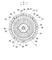
第二実施形態のバルブタイミング調整装置100では、駆動側回転体10に排出孔80が設けられるのみならず、従動側回転体20にも排出孔110が設けられている。具体的に排出孔110は、従動側回転体20の従動側内歯車部22において回転方向に略等間隔をあけた八箇所に設けられている。各排出孔110は、従動側内歯車部22の軸方向中間部を径方向へストレートに貫通している。各排出孔110の出口部は従動側内歯車部22の外周側へ向かって開口し、回転体10,20の外部と連通している。各排出孔110の入口部は、遊星歯車50の遊星運動を阻害し難くすべく、従動側内歯車部22において対応する歯底112に開口し、内部空間11と連通している。
(Second embodiment)
As shown in FIGS. 7 and 8, the second embodiment of the present invention is a modification of the first embodiment.
In the valve
このようなバルブタイミング調整装置100によると、内燃機関の運転と共に内部空間11へ導入されて内、外歯車部22,54間を流動する潤滑油は、従動側回転体20の回転による遠心力や、従動側内歯車部22の排出孔110近傍の歯に噛合しようとする従動側外歯車部54の歯の押出力によって、従動側内歯車部22の歯底112に開口する各排出孔110へ容易に流入し得る。また、各排出孔110へ流入した潤滑油は、従動側内歯車部22を径方向へ貫通する各排出孔110の内部では、遠心力を受けつつも小さな流動抵抗にて流れ得る。したがって、各排出孔110によっても、第一実施形態で説明した各排出孔80による場合と同様の作用効果を享受することができるので、潤滑油の排出効率、ひいては作動不良及び破損の防止効果がさらに高くなる。
尚、ここまで説明した第二実施形態では、駆動側回転体10及び従動側回転体20が特許請求の範囲に記載の「特定回転体」に相当し、駆動側内歯車部14及び従動側内歯車部22が特許請求の範囲に記載の「内歯車部」に相当する。
According to such a valve
In the second embodiment described so far, the drive-
(第三実施形態)
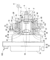
図9,10に示すように、本発明の第三実施形態は第一実施形態の変形例である。
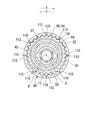
第三実施形態のバルブタイミング調整装置200において従動側回転体210は、周壁部211によって従動側内歯車部22を形成しておらず、その代わりに、周壁部211においてフランジ部23側の端面に開口する係合孔212を複数有している。ここで各係合孔212は円筒孔状であり、周壁部211の回転方向に並んで設けられている。
(Third embodiment)
As shown in FIGS. 9 and 10, the third embodiment of the present invention is a modification of the first embodiment.
In the valve
また、バルブタイミング調整装置200において遊星歯車220は、従動側外歯車部54を形成する小径部分を有しておらず、その代わりに、駆動側外歯車部52において周壁部211と対向する端面から突出する係合突起222を係合孔212と同数有している。ここで各係合突起222は円柱状であり、駆動側外歯車部52の回転方向に並んで設けられている。各係合突起222は対応する係合孔212へ突入しており、それによって内部空間11には、駆動側内歯車部14と従動側回転体210とが遊星歯車220を介して連繋してなる差動歯車機構230が形成されている。
Further, in the valve
この差動歯車機構230において、遊星キャリヤ40が駆動側回転体10に対して相対回転しないときには、遊星歯車220が内、外歯車部14,52の噛合位置を保ちつつ駆動側回転体10と共に回転し、各係合突起222が各係合孔212を回転側へ押圧する。その結果、従動側回転体210が駆動側回転体10との間の相対回転位相を保ちつつ回転するため、バルブタイミングが保持される。一方、遊星キャリヤ40が駆動側回転体10に対して方向Yへ相対回転するときには、遊星歯車220が内、外歯車部14,52の噛合位置を変化させつつ遊星運動することで、各係合突起222が各係合孔212を回転側へ押圧する力が増大する。その結果、従動側回転体210が駆動側回転体10に対して方向Xへ相対回転するため、バルブタイミングが進角側へ変移する。また一方、遊星キャリヤ40が駆動側回転体10に対して方向Xへ相対回転するときには、遊星歯車220が内、外歯車部14,52の噛合位置を変化させつつ遊星運動することで、各係合突起222が各係合孔212を反回転側へ押圧する。その結果、従動側回転体210が駆動側回転体10に対して方向Yへ相対回転するため、バルブタイミングが遅角側へ変移する。
In this
以上の特徴を有するバルブタイミング調整装置200においても、第一実施形態と同一構成の排出孔80が八つ設けられる。故に、内燃機関の運転と共に内部空間11へ導入されて内、外歯車部14,52間を通過した潤滑油は、駆動側内歯車部14の所定の歯底82から各排出孔80へ流入した後、それら各排出孔80の案内によって駆動側内歯車部14の外周側へ排出される。また、内燃機関が停止すると、その停止前に内部空間11へ導入されていた潤滑油は、駆動側内歯車部14において回転軸線Oを含む水平面より下側に位置する排出孔80を通じて駆動側内歯車部14の外周側へと排出される。したがって、このようなバルブタイミング調整装置200によっても、第一実施形態と同様の効果を享受することができる。
尚、ここまで説明した第三実施形態では、遊星歯車220に直接連繋する従動側回転体210が特許請求の範囲に記載の「第二回転体」に相当する。
Also in the valve
In the third embodiment described so far, the driven-
(第四実施形態)
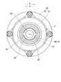
図11〜13に示すように、本発明の第四実施形態は第三実施形態の変形例である。尚、図12,13では、断面を表すハッチングの図示を省略している。
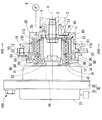
第四実施形態のバルブタイミング調整装置300では、係合孔212及びフランジ部23が従動側回転体310に設けられず、その代わりに、回転体10,310と同軸に配置される円環板状の案内回転体320が追加され、当該案内回転体320に係合孔212が設けられている。ここで案内回転体320は、従動側回転体310の周壁部311に嵌合することで回転軸線O周りに回転可能となっており、また回転体10,310に対して相対回転可能となっている。また、案内回転体320の回転方向に並ぶ複数の係合孔212には、遊星歯車220の対応する係合突起222が突入しており、それによって内部空間11には、駆動側内歯車部14と案内回転体320とが遊星歯車220を介して連繋してなる差動歯車機構330が形成されている。
(Fourth embodiment)
As shown in FIGS. 11-13, 4th embodiment of this invention is a modification of 3rd embodiment. In FIGS. 12 and 13, hatching representing a cross section is omitted.
In the valve
したがって、差動歯車機構330では、遊星キャリヤ40が駆動側回転体10に対して相対回転しないときには、遊星歯車220が内、外歯車部14,52の噛合位置を保つことで、案内回転体320が駆動側回転体10との間の相対回転位相を保って回転する。一方、遊星キャリヤ40が駆動側回転体10に対して方向Yへ相対回転するときには、遊星歯車220が内、外歯車部14,52の噛合位置を変化させつつ遊星運動することで、案内回転体320が駆動側回転体10に対して方向Xへ相対回転する。また一方、遊星キャリヤ40が駆動側回転体10に対して方向Xへ相対回転するときには、遊星歯車220が内、外歯車部14,52の噛合位置を変化させつつ遊星運動することで、案内回転体320が駆動側回転体10に対して方向Yへ相対回転する。
Therefore, in the
さて、バルブタイミング調整装置300の従動側回転体310はさらに、周壁部311から外周側へ突出する連繋部312を有している。ここで各連携部312は平板状であり、周壁部311において回転軸線Oに関して対称となる二箇所にそれぞれ設けられている。
さらにバルブタイミング調整装置300では、駆動側回転体10のスプロケット340に円環板状の接続部342が回転軸線Oに対して垂直に設けられている。
Now, the driven-
Further, in the valve
またさらにバルブタイミング調整装置300では、二組のリンク機構部351、溝形成部354及び一対の可動体355等からなる位相変化機構350が追加されている。各組のリンク機構部351の第一リンク352は円弧形の平板状に形成されており、それぞれ接続部342において回転軸線Oに関して対称となる二箇所に回り対偶によって連繋している。各組のリンク機構部351の第二リンク353は円弧形の平板状に形成されており、対応する連繋部312に回り対偶によって連繋し且つ同一組のリンク機構部351の第一リンク352に可動体355を介した回り対偶によって連繋している。溝形成部354は案内回転体320に設けられ、回転軸線Oに関して対称となる二箇所に案内溝358を形成している。各案内溝358は回転軸線Oの外周側を所定の幅をもって延伸し、その延伸方向において回転軸線Oからの距離が変化している。円柱軸状の各可動体355は、対応する案内溝358内に滑動自在に嵌合し、対応する第一リンク352に相対回転自在に嵌合し、さらに対応する第二リンク353に圧入固定されている。
Further, in the valve
こうした構成の位相変化機構350において、案内回転体320が駆動側回転体10との間の相対回転位相を保っているときには、各可動体355が案内溝358により案内されず、各組のリンク機構部351ではリンク352,353の位置が保持される。その結果、従動側回転体310が駆動側回転体10との間の相対回転位相を保ちつつ回転するため、バルブタイミングが保持される。一方、案内回転体320が駆動側回転体10に対して方向Xへ相対回転するときには、各可動体355が案内溝358により案内されて回転軸線Oから離間することで、各組のリンク機構部351では、第一リンク352が回動しつつ第二リンク353が連繋部312と共に方向Yへ移動する。その結果、従動側回転体210が駆動側回転体10に対して方向Yへ相対回転するため、バルブタイミングが遅角側へ変移する。また一方、案内回転体320が駆動側回転体10に対して方向Yへ相対回転するときには、各可動体355が案内溝358により案内されて回転軸線Oへ接近することで、各組のリンク機構部351では、第一リンク352が回動しつつ第二リンク353が連繋部312と共に方向Xへ移動する。その結果、従動側回転体210が駆動側回転体10に対して方向Xへ相対回転するため、バルブタイミングが進角側へ変移する。
In the
以上の特徴を有するバルブタイミング調整装置300においても、第一実施形態と同一構成の排出孔80が八つ設けられる。故に、内燃機関の運転と共に内部空間11へ導入されて位相変化機構350、案内回転体320と他の回転体10,310の間並びに内、外歯車部14,52間を順次通過した潤滑油は、各排出孔80によって駆動側内歯車部14の歯底82から当該歯車部14の外周側へ排出される。また、内燃機関が停止すると、その停止前に内部空間11へ導入されていた潤滑油は、駆動側内歯車部14において回転軸線Oを含む水平面より下側に位置する排出孔80を通じて駆動側内歯車部14の外周側へと排出される。したがって、このようなバルブタイミング調整装置300によっても、第一実施形態と同様の効果を享受することができる。
尚、ここまで説明した第四実施形態では、案内回転体320及び位相変化機構350を介して間接的に遊星歯車220に連繋する従動側回転体310が特許請求の範囲に記載の「第二回転体」に相当する。
Also in the valve
In the fourth embodiment described so far, the driven-
以上、本発明の複数の実施形態について説明してきたが、本発明はそれらの実施形態に限定して解釈されるものではなく、その要旨を逸脱しない範囲内において種々の実施形態に適用可能である。
例えば第一〜第四実施形態では、排出孔80,110をそれぞれ八つ、導入孔70を二つ設けているが、排出孔80,110及び導入孔70の数については、要求に応じて適宜設定することができる。
Although a plurality of embodiments of the present invention have been described above, the present invention is not construed as being limited to these embodiments, and can be applied to various embodiments without departing from the scope of the present invention. .
For example, in the first to fourth embodiments, eight discharge holes 80 and 110 and two introduction holes 70 are provided, respectively, but the number of discharge holes 80 and 110 and introduction holes 70 is appropriately determined according to requirements. Can be set.
また、第一〜第四実施形態において排出孔80,110の形状は、潤滑油を内歯車部14,22の歯底82,112から回転体10,20の外周側へ案内可能な形状であればよく、図14に変形例(同図は第一実施形態の排出孔80の変形例)を示すように回転軸線Oに対して傾斜する形状等であってもよい。
Further, in the first to fourth embodiments, the shape of the discharge holes 80 and 110 may be a shape capable of guiding the lubricating oil from the
さらに第一〜第四実施形態では、排出孔80,110に加えて、回転体10,20の軸方向外側へ潤滑油を案内して排出する排出孔を設けてもよい。
またさらに第二実施形態では、図15に変形例を示すように排出孔80を設けなくてもよい。尚、この場合には、従動側回転体20が特許請求の範囲に記載の「特定回転体」に相当し、従動側内歯車部22が特許請求の範囲に記載の「内歯車部」に相当する。
Furthermore, in 1st-4th embodiment, in addition to the discharge holes 80 and 110, you may provide the discharge hole which guides and discharge | releases lubricating oil to the axial direction outer side of the
Furthermore, in the second embodiment, the
加えて第一〜第四実施形態では、回転体10をカム軸2に連動して回転させ、回転体20,210,310をクランク軸に連動して回転させてもよい。尚、この場合には、回転体10が特許請求の範囲に記載の「第二回転体」に相当し、回転体20,210,310が特許請求の範囲に記載の「第一回転体」に相当する。
In addition, in the first to fourth embodiments, the rotating
また加えて第一〜第四実施形態では、電動モータ32に代えて、クランク軸の駆動トルクが伝達されることにより回転するブレーキ部材並びにブレーキ部材を磁気吸引するソレノイドを有し、ソレノイドに磁気吸引されたブレーキ部材に生じる制動トルクを回転トルクとして発生する電磁ブレーキ装置や、油圧モータ等を用いてもよい。
さらに加えて本発明は、第一〜第四実施形態のように吸気弁のバルブタイミングを調整する装置以外にも、排気弁のバルブタイミングを調整する装置や、吸気弁及び排気弁の双方のバルブタイミングを調整する装置に適用してもよい。
In addition, in the first to fourth embodiments, instead of the
In addition to the devices for adjusting the valve timing of the intake valve as in the first to fourth embodiments, the present invention also includes a device for adjusting the valve timing of the exhaust valve, and valves for both the intake valve and the exhaust valve. You may apply to the apparatus which adjusts timing.
1,100,200,300 バルブタイミング調整装置、2 カム軸、4 ポンプ、5 供給孔、10 駆動側回転体(特定回転体、第一回転体)、11 内部空間、12 歯車部材、13,340 スプロケット、14 駆動側内歯車部(内歯車部、第一内歯車部)、18 底壁部、20,210,310 従動側回転体(第二回転体、特定回転体)、21 固定部、22 従動側内歯車部(第二内歯車部、内歯車部)、23 フランジ部、30 制御ユニット、32 電動モータ、33 通電制御回路、40 遊星キャリヤ、50,220 遊星歯車、52 駆動側外歯車部(第一外歯車部)、54 従動側外歯車部(第二外歯車部)、60,230,330 差動歯車機構、70 導入孔、80,110 排出孔、82,112 歯底、84 歯先、211,311 周壁部、212 係合孔、222 係合突起、312 連繋部、320 案内回転体、342 接続部、350 位相変化機構
1,100,200,300 Valve timing adjusting device, 2 cam shaft, 4 pump, 5 supply hole, 10 drive side rotating body (specific rotating body, first rotating body), 11 internal space, 12 gear member, 13,340 Sprocket, 14 driving side internal gear part (internal gear part, first internal gear part), 18 bottom wall part, 20, 210, 310 driven side rotating body (second rotating body, specific rotating body), 21 fixing part, 22 Drive side internal gear part (second internal gear part, internal gear part), 23 flange part, 30 control unit, 32 electric motor, 33 energization control circuit, 40 planetary carrier, 50, 220 planetary gear, 52 drive side external gear part (First external gear portion), 54 driven side external gear portion (second external gear portion), 60, 230, 330 differential gear mechanism, 70 introduction hole, 80, 110 discharge hole, 82, 112 tooth bottom, 84 teeth Ahead, 211,311 wall , 212 engaging hole, 222 engagement projection, 312 interlocking portion, 320 guide the rotating body, 342 connecting portion, 350 a phase change mechanism
Claims (7)
前記クランク軸に連動して回転する第一回転体と、
前記カム軸に連動して回転する第二回転体と、
前記第一回転体及び前記第二回転体のうち少なくとも一方である特定回転体に設けられる内歯車部と、
前記内歯車部に噛合しつつ遊星運動することにより前記第一回転体及び前記第二回転体の間の相対回転位相を変化させる遊星歯車と、
を備え、
前記特定回転体は、前記特定回転体の内部へ導入された潤滑流体を前記内歯車部の歯底から前記特定回転体の外周側へ案内して排出する排出孔を有することを特徴とするバルブタイミング調整装置。 A valve timing adjustment device for an internal combustion engine that adjusts the valve timing of at least one of an intake valve and an exhaust valve whose camshaft opens and closes by torque transmission from a crankshaft,
A first rotating body that rotates in conjunction with the crankshaft;
A second rotating body that rotates in conjunction with the camshaft;
An internal gear provided in a specific rotating body that is at least one of the first rotating body and the second rotating body;
A planetary gear that changes a relative rotational phase between the first rotating body and the second rotating body by performing planetary movement while meshing with the internal gear portion;
With
The specific rotator has a discharge hole that guides and discharges the lubricating fluid introduced into the specific rotator from the tooth bottom of the internal gear portion to the outer peripheral side of the specific rotator. Timing adjustment device.
前記特定回転体の軸方向は、水平方向と実質的に一致することを特徴とする請求項2に記載のバルブタイミング調整装置。 The lubricating fluid is introduced into the specific rotating body along with the operation of the internal combustion engine,
The valve timing adjusting device according to claim 2, wherein an axial direction of the specific rotating body substantially coincides with a horizontal direction.
前記遊星歯車は、第一外歯車部及び第二外歯車部を有し、前記第一外歯車部及び前記第二外歯車部がそれぞれ前記第一内歯車部及び前記第二内歯車部に噛合しつつ一体に遊星運動することにより前記相対回転位相を変化させることを特徴とする請求項1〜4のいずれか一項に記載のバルブタイミング調整装置。 A first internal gear portion is provided in the first rotating body, and a second internal gear portion that is positioned axially offset from the first internal gear portion is provided in the second rotating body, and these first internal gear portions And at least one of the second internal gear portions provided on the specific rotating body is the internal gear portion,
The planetary gear has a first external gear portion and a second external gear portion, and the first external gear portion and the second external gear portion mesh with the first internal gear portion and the second internal gear portion, respectively. The valve timing adjusting device according to any one of claims 1 to 4, wherein the relative rotational phase is changed by a planetary motion integrally.
前記遊星キャリヤへ与える回転トルクを発生する電動モータと、
を備えることを特徴とする請求項1〜6のいずれか一項に記載のバルブタイミング調整装置。
A planet carrier that rotatably supports the planetary gear and rotates in the revolution direction of the planetary gear;
An electric motor for generating rotational torque to be applied to the planet carrier;
The valve timing adjusting device according to any one of claims 1 to 6, further comprising:
Priority Applications (1)
| Application Number | Priority Date | Filing Date | Title |
|---|---|---|---|
| JP2006064100A JP2007239642A (en) | 2006-03-09 | 2006-03-09 | Valve timing adjusting device |
Applications Claiming Priority (1)
| Application Number | Priority Date | Filing Date | Title |
|---|---|---|---|
| JP2006064100A JP2007239642A (en) | 2006-03-09 | 2006-03-09 | Valve timing adjusting device |
Publications (2)
| Publication Number | Publication Date |
|---|---|
| JP2007239642A true JP2007239642A (en) | 2007-09-20 |
| JP2007239642A5 JP2007239642A5 (en) | 2008-05-22 |
Family
ID=38585423
Family Applications (1)
| Application Number | Title | Priority Date | Filing Date |
|---|---|---|---|
| JP2006064100A Withdrawn JP2007239642A (en) | 2006-03-09 | 2006-03-09 | Valve timing adjusting device |
Country Status (1)
| Country | Link |
|---|---|
| JP (1) | JP2007239642A (en) |
Cited By (9)
| Publication number | Priority date | Publication date | Assignee | Title |
|---|---|---|---|---|
| JP2009114921A (en) * | 2007-11-05 | 2009-05-28 | Denso Corp | Valve timing adjustment device |
| JP2009209794A (en) * | 2008-03-04 | 2009-09-17 | Denso Corp | Valve-timing adjusting device |
| JP2010159706A (en) * | 2009-01-08 | 2010-07-22 | Denso Corp | Valve timing adjusting device |
| JP2010168962A (en) * | 2009-01-21 | 2010-08-05 | Denso Corp | Valve timing adjusting device |
| CN102191962A (en) * | 2010-03-10 | 2011-09-21 | 通用汽车环球科技运作有限责任公司 | Engine with dual cam phaser for concentric camshaft |
| JP2012087697A (en) * | 2010-10-20 | 2012-05-10 | Denso Corp | Variable valve timing device |
| JP2012145122A (en) * | 2011-01-06 | 2012-08-02 | Hitachi Constr Mach Co Ltd | Gear coupling |
| WO2018219377A1 (en) * | 2017-06-01 | 2018-12-06 | Schaeffler Technologies AG & Co. KG | Triple-shaft transmission |
| JP2020125688A (en) * | 2019-02-01 | 2020-08-20 | 株式会社デンソー | Valve timing adjustment device |
-
2006
- 2006-03-09 JP JP2006064100A patent/JP2007239642A/en not_active Withdrawn
Cited By (11)
| Publication number | Priority date | Publication date | Assignee | Title |
|---|---|---|---|---|
| JP2009114921A (en) * | 2007-11-05 | 2009-05-28 | Denso Corp | Valve timing adjustment device |
| JP2009209794A (en) * | 2008-03-04 | 2009-09-17 | Denso Corp | Valve-timing adjusting device |
| JP2010159706A (en) * | 2009-01-08 | 2010-07-22 | Denso Corp | Valve timing adjusting device |
| JP2010168962A (en) * | 2009-01-21 | 2010-08-05 | Denso Corp | Valve timing adjusting device |
| US8251029B2 (en) | 2009-01-21 | 2012-08-28 | Denso Corporation | Valve timing controller |
| CN102191962A (en) * | 2010-03-10 | 2011-09-21 | 通用汽车环球科技运作有限责任公司 | Engine with dual cam phaser for concentric camshaft |
| JP2012087697A (en) * | 2010-10-20 | 2012-05-10 | Denso Corp | Variable valve timing device |
| JP2012145122A (en) * | 2011-01-06 | 2012-08-02 | Hitachi Constr Mach Co Ltd | Gear coupling |
| WO2018219377A1 (en) * | 2017-06-01 | 2018-12-06 | Schaeffler Technologies AG & Co. KG | Triple-shaft transmission |
| JP2020125688A (en) * | 2019-02-01 | 2020-08-20 | 株式会社デンソー | Valve timing adjustment device |
| JP7198099B2 (en) | 2019-02-01 | 2022-12-28 | 株式会社デンソー | valve timing adjuster |
Similar Documents
| Publication | Publication Date | Title |
|---|---|---|
| JP2008095549A (en) | Valve timing adjusting device | |
| JP4735720B2 (en) | Valve timing adjustment device | |
| EP2386732B1 (en) | Harmonic drive camshaft phaser with a compact drive sprocket | |
| US8726865B2 (en) | Harmonic drive camshaft phaser using oil for lubrication | |
| US9534513B2 (en) | Camshaft phaser actuated by an electric motor | |
| JP2004003419A (en) | Valve timing regulator | |
| JP2007239642A (en) | Valve timing adjusting device | |
| JP2008095550A (en) | Valve timing adjustment device | |
| JP4900286B2 (en) | Valve timing adjustment device | |
| JP4877199B2 (en) | Valve timing adjustment device | |
| US7314030B2 (en) | Valve timing adjusting apparatus | |
| JP4419091B2 (en) | Valve timing adjustment device | |
| JP6145716B2 (en) | Valve timing adjustment device | |
| KR20110104009A (en) | Mini electric cam phaser | |
| JP5240309B2 (en) | Valve timing adjustment device | |
| JP5218249B2 (en) | Valve timing adjustment device | |
| JP4678537B2 (en) | Valve timing adjustment device | |
| JP2009019595A (en) | Valve timing adjusting device | |
| JP2007071057A (en) | Valve timing adjusting device | |
| JP2008248804A (en) | Valve timing adjusting device | |
| JP2008215312A (en) | Valve timing device | |
| JP2009074398A (en) | Valve timing adjusting device | |
| JP4447564B2 (en) | Valve timing adjustment device | |
| JP7186881B2 (en) | Reducer and variable valve timing device | |
| JP5991274B2 (en) | Valve timing adjustment device |
Legal Events
| Date | Code | Title | Description |
|---|---|---|---|
| A521 | Written amendment |
Free format text: JAPANESE INTERMEDIATE CODE: A523 Effective date: 20080408 |
|
| A621 | Written request for application examination |
Free format text: JAPANESE INTERMEDIATE CODE: A621 Effective date: 20080408 |
|
| A761 | Written withdrawal of application |
Free format text: JAPANESE INTERMEDIATE CODE: A761 Effective date: 20090721 |