JP2007239245A - Human body private parts washing device - Google Patents
Human body private parts washing device Download PDFInfo
- Publication number
- JP2007239245A JP2007239245A JP2006060691A JP2006060691A JP2007239245A JP 2007239245 A JP2007239245 A JP 2007239245A JP 2006060691 A JP2006060691 A JP 2006060691A JP 2006060691 A JP2006060691 A JP 2006060691A JP 2007239245 A JP2007239245 A JP 2007239245A
- Authority
- JP
- Japan
- Prior art keywords
- nozzle
- nozzle body
- small
- diameter cylindrical
- guide slit
- Prior art date
- Legal status (The legal status is an assumption and is not a legal conclusion. Google has not performed a legal analysis and makes no representation as to the accuracy of the status listed.)
- Pending
Links
Images


Abstract
Description
本発明は、水洗便器に設置される人体局部洗浄装置に関し、特に、洗浄水を噴出するノズルの汚れを洗浄可能な人体局部洗浄装置に関するものである。 The present invention relates to a human body local cleaning device installed in a flush toilet, and more particularly to a human body local cleaning device capable of cleaning dirt on a nozzle that ejects cleaning water.
一般に、この種の人体局部洗浄装置は、洗浄水を噴出するノズルをケーシングに収納し、ノズルの先端がケーシング内に入った位置から洗浄動作を行う位置まで、ケーシングの出入口を通して往復移動するようにしている。洗浄動作をするとき、ノズルが人体局部に接近するので、ノズルに汚水や汚物が付着し易くなる。そのため、ノズルに筒状のノズルカバー体を着脱可能に取付けて、少なくともノズルの先端付近に汚水や汚物の付着による汚染を防止している。このとき、ノズルと重なり合う吐出孔をノズルカバーに設けて、ノズルから噴出する洗浄水が吐出孔を通って噴出するようにしている。 In general, this type of human body local cleaning device stores a nozzle that ejects cleaning water in a casing, and reciprocates through the inlet / outlet of the casing from the position where the nozzle tip enters the casing to the position where the cleaning operation is performed. ing. When performing the cleaning operation, the nozzle approaches the human body part, so that sewage and filth easily adhere to the nozzle. Therefore, a cylindrical nozzle cover body is detachably attached to the nozzle to prevent contamination due to adhesion of dirty water or filth at least near the tip of the nozzle. At this time, a discharge hole overlapping with the nozzle is provided in the nozzle cover so that the cleaning water sprayed from the nozzle is ejected through the discharge hole.
具体的には、従来の人体局部洗浄装置として特許文献1の発明がある。即ち、洗浄水を噴出する先端部を有するノズル本体と、ノズルと重なり合う吐出孔を有し、ノズル本体を覆う筒状のノズルカバーと、ノズル本体を軸方向に往復移動させるノズル駆動部とを設け、ノズル本体及びノズルカバーは、互いに係合してノズルカバーとノズル本体とを着脱可能に固定する係合片を有し、ノズルカバーをノズル本体に挿入して係合片を係合させることにより、ノズルカバーとノズル本体とを固定する挿着力は、ノズル駆動部がノズル本体を静止状態に保持する保持力より小さく形成する技術が開示されている。
ところで、上記特許文献1では、ノズルカバーをノズル本体に挿入して係合片を係合させる構成が、L字状の溝または螺子を用いたものであるから、扱いに不慣れな人が部品の組み付けを行った場合、締め付けの程度が分からず、不十分な取付け状態となり、洗浄水の噴出が弱くなる可能性がある。 By the way, in the above-mentioned patent document 1, since the configuration in which the nozzle cover is inserted into the nozzle body and the engaging piece is engaged is an L-shaped groove or screw, a person unaccustomed to handling the parts When assembled, the degree of tightening is not known, resulting in an inadequate mounting state, and the jet of cleaning water may be weakened.
そこで、この発明はかかる不具合を解決するためになされたもので、扱いに不慣れな人による組みつけが容易であり、手の感触においても、視覚的にも組付け完了を確認できる人体局部洗浄装置の提供を課題とするものである。 Accordingly, the present invention has been made to solve such a problem, and is easy to assemble by a person unfamiliar with handling, and the human body local cleaning device that can confirm the completion of the assembly visually as well as with the feel of the hand The issue is to provide
請求項1にかかる人体局部洗浄装置のノズル本体は、主要部、前記主要部の先端に形成され、かつ、前記主要部の径よりも小径の小径筒状部及び前記小径筒状部に配設される係合片とを有するノズル本体と、前記ノズル本体の小径筒状部に配設された1個以上のOリングと、前記ノズル本体の小径筒状部を覆うように挿着されるノズルカバーとを具備し、前記ノズルカバーは、前記Oリングと弾接する内径を有し、前記ノズル本体の長さ方向に挿入するとき、前記小径筒状部に配設した係合片を所定の位置までガイドする長さ方向案内スリットと、前記長さ方向案内スリットから連続して回転方向に所定の幅だけ回動自在で、前記小径筒状部に配設した係合片の幅以下の溝を部分的に形成してなる回転方向案内スリットとを有し、挿着時に、前記長さ方向案内スリットから前記回転方向案内スリットへと回動したとき、前記係合片との間でスナップ動作を行って係合するものである。
ここで、ノズル本体の移動駆動部となる主要部は、少なくとも一面を平面とし、その平面を用いてラックを形成し、当該ラックと噛み合うピニオンの回転によってハウジングから伸縮移動自在とするものであればよい。更には、ノズル本体は公知の水圧駆動式でもよい。また、ノズル本体の小径筒状部は、前記主要部の先端に前記主要部の径よりも小径に形成したもので、その外周は略円筒状とするものであればよい。そして、ノズル本体の係合片は、ノズルカバーの回転方向案内スリットと共にスナップ動作を行うものであればよい。
ノズルカバーは、ノズル本体の小径筒状部を覆うように挿着されると共に、Oリングと弾接する内径を有し、前記ノズル本体の長さ方向に挿入できるものであればよい。また、ノズルカバーの回転方向案内スリットは、長さ方向案内スリットから連続して回転方向に所定の幅だけ形成され、前記小径筒状部に配設した係合片の幅以下の溝を一部に形成し、かつ、前記長さ方向案内スリットから前記回転方向案内スリットへと前記円柱係合片との係合を行うスナップ動作を行うものであればよい。
The nozzle body of the human body local cleaning device according to claim 1 is formed in a main part, a tip of the main part, and a small diameter cylindrical part having a smaller diameter than the diameter of the main part and the small diameter cylindrical part. A nozzle body having an engagement piece to be operated, one or more O-rings disposed in the small-diameter cylindrical portion of the nozzle main body, and a nozzle inserted so as to cover the small-diameter cylindrical portion of the nozzle main body And the nozzle cover has an inner diameter that elastically contacts the O-ring, and when inserted in the length direction of the nozzle body, the engagement piece disposed in the small-diameter cylindrical portion is positioned at a predetermined position. A longitudinal guide slit that guides to the groove, and a groove that is continuously rotatable from the longitudinal guide slit by a predetermined width in the rotational direction and that is less than or equal to the width of the engagement piece disposed in the small-diameter cylindrical portion. It has a rotation direction guide slit formed partially, and at the time of insertion, When the Sulfur butterfly direction guide slit pivoted to the rotational direction guide slit, it is intended to engage by performing a snap operation between the engagement piece.
Here, the main part that is the movement drive unit of the nozzle body is at least one surface as a flat surface, a rack is formed using the flat surface, and it can be extended and retracted from the housing by rotation of a pinion that meshes with the rack. Good. Furthermore, the nozzle body may be a known water pressure drive type. Further, the small-diameter cylindrical portion of the nozzle body is formed at the tip of the main portion so as to have a diameter smaller than the diameter of the main portion, and the outer periphery thereof may be substantially cylindrical. And the engagement piece of a nozzle main body should just perform a snap operation | movement with the rotation direction guide slit of a nozzle cover.
The nozzle cover only needs to be inserted so as to cover the small-diameter cylindrical portion of the nozzle body, have an inner diameter that elastically contacts the O-ring, and can be inserted in the length direction of the nozzle body. In addition, the rotation direction guide slit of the nozzle cover is formed to have a predetermined width in the rotation direction continuously from the length direction guide slit, and a part of the groove having a width equal to or less than the width of the engagement piece disposed in the small-diameter cylindrical portion. And a snap operation for engaging with the columnar engagement piece from the longitudinal guide slit to the rotational guide slit.
請求項2にかかる人体局部洗浄装置の前記ノズルカバーの外形と前記ノズル本体とは、前記係合状態で少なくともその外表面の一部を連続した形態としたものである。ここで、少なくともその外表面の一部とは、中心角度30度程度以上の周囲を意味し、外表面の一部以上を意味する。
The outer shape of the nozzle cover and the nozzle body of the human body local cleaning device according to
請求項3にかかる人体局部洗浄装置の前記ノズルカバーの外形と前記ノズル本体とは、断面略小判形としたものである。 The outer shape of the nozzle cover and the nozzle body of the human body local cleaning device according to claim 3 are substantially oval in cross section.
請求項1の人体局部洗浄装置によれば、ノズル本体の先端は主要部の径よりも小径に形成し、その外周を円筒に形成した小径筒状部となっている。前記ノズル本体の小径筒状部を覆うように挿着されるノズルカバーは、前記ノズル本体の長さ方向に挿入するとき、内径がOリングと弾接し、長さ方向案内スリットが前記小径筒状部に配設した係合片を所定の位置までガイドする。その後、前記長さ方向案内スリットから連続して形成された回転方向案内スリットに係合片を導き、更に回動すると、スナップ動作を行い前記係合片との係合を行う。このとき、スナップ動作によってノズルカバーは、ノズル本体の小径筒状部の係合片との係合を行うことにより、手の感覚として両者がロックされたことを認識できる。また、ノズルカバーの回転方向案内スリットと係合片の位置により、目視によっても係合を認識できる。更に、ノズルカバーとOリングとが弾接しているから、回動する回転力に対して、反対方向の弾性エネルギが蓄積されているが、スナップ動作によって係合しているから、ノズルカバー30,70は安定な取り付け状態が維持できる。 According to the human body local cleaning device of the first aspect, the tip of the nozzle body is formed to have a smaller diameter than the diameter of the main part, and the outer periphery thereof is a small diameter cylindrical part formed into a cylinder. The nozzle cover that is inserted so as to cover the small-diameter cylindrical portion of the nozzle main body elastically contacts the O-ring when inserted in the length direction of the nozzle main body, and the length-direction guide slit is the small-diameter cylindrical shape. The engaging piece arranged in the section is guided to a predetermined position. Thereafter, the engaging piece is guided to a rotational direction guiding slit formed continuously from the longitudinal direction guiding slit, and further rotated, a snap operation is performed to engage with the engaging piece. At this time, it is possible to recognize that the nozzle cover is locked as a hand sensation by engaging the engagement portion with the engagement piece of the small diameter cylindrical portion of the nozzle body by the snap operation. Further, the engagement can be recognized visually by the position of the rotation direction guide slit of the nozzle cover and the engagement piece. Further, since the nozzle cover and the O-ring are elastically contacted, elastic energy in the opposite direction is accumulated with respect to the rotating rotational force. 70 can maintain a stable attachment state.
請求項2にかかる人体局部洗浄装置の前記ノズルカバーの外形と前記ノズル本体とは、少なくとも一部を係合状態で連続した形態としたものであるから、目視においても、手による接触感覚においてもノズルカバーとノズル本体との一致が確認できる。
Since the outer shape of the nozzle cover and the nozzle body of the human body local cleaning device according to
請求項3の人体局部洗浄装置によれば、前記ノズルカバー体の外形と前記ノズル本体とは、断面略小判形としたものであるから、目視においても、手による接触感覚においてもノズルカバーとノズル本体との一致が確認できる。 According to the human body local cleaning device according to claim 3, since the outer shape of the nozzle cover body and the nozzle body have a substantially oval cross section, the nozzle cover and the nozzle can be seen both visually and by touch. The match with the main body can be confirmed.
以下、本発明の実施の形態について、図面に基づいて説明する。
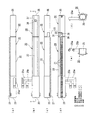
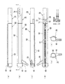
図1は本発明の実施の形態1における人体局部洗浄装置の全体斜視図、図2は本発明の実施の形態1における人体局部洗浄装置の右側面図、図3は本発明の実施の形態1における人体局部洗浄装置の左側面図、図4は図2の矢印A方向から見たA矢視図、図5は本発明の実施の形態1における人体局部洗浄装置のノズル本体を下方向に移動させた状態の右側面図、図6は本発明の実施の形態1における人体局部洗浄装置のシャワー用ノズル本体の右側面図(a)、平面図(b)、左側面図(c)、底面図(d)、上面図(e)、下面図(f)である。図7は本発明の実施の形態1における人体局部洗浄装置のシャワー用ノズル本体の平面図(b)の切断線Y−Yによる拡大断面図、図8は本発明の実施の形態1における人体局部洗浄装置のシャワー用ノズル本体及びノズルカバーとの着脱関係を示す斜視図である。そして、図9は本発明の実施の形態1における人体局部洗浄装置のビデ用ノズル本体の右側面図(a)、平面図(b)、左側面図(c)、底面図(d)、上面図(e)、下面図(f)である。図10は本発明の実施の形態1における人体局部洗浄装置のビデ用ノズル本体の平面図(b)の切断線Z−Zによる拡大断面図、図11は本発明の実施の形態1における人体局部洗浄装置のビデ用ノズル本体及びノズルカバーとの着脱関係を示す斜視図である。
Hereinafter, embodiments of the present invention will be described with reference to the drawings.
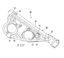
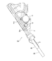
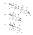
1 is an overall perspective view of a human body local cleaning device according to Embodiment 1 of the present invention, FIG. 2 is a right side view of the human body local cleaning device according to Embodiment 1 of the present invention, and FIG. 3 is Embodiment 1 of the present invention. 4 is a left side view of the human body local cleaning device in FIG. 4, FIG. 4 is a view as seen from the direction of arrow A in FIG. 2, and FIG. 5 is a downward movement of the nozzle body of the human body local cleaning device in Embodiment 1 of the present invention. FIG. 6 is a right side view (a), a plan view (b), a left side view (c), and a bottom surface of the shower nozzle body of the human body local cleaning device according to the first embodiment of the present invention. It is a figure (d), a top view (e), and a bottom view (f). FIG. 7 is an enlarged cross-sectional view taken along the cutting line YY of the plan view (b) of the shower nozzle body of the human body local cleaning device according to the first embodiment of the present invention, and FIG. 8 is a human body local section according to the first embodiment of the present invention. It is a perspective view which shows the attachment or detachment relationship with the nozzle body for showers of a washing | cleaning apparatus, and a nozzle cover. FIG. 9 is a right side view (a), a plan view (b), a left side view (c), a bottom view (d), and a top view of the bidet nozzle body of the human body local cleaning device according to the first embodiment of the present invention. It is a figure (e) and a bottom view (f). FIG. 10 is an enlarged cross-sectional view taken along the cutting line ZZ in the plan view (b) of the bidet nozzle body of the human body local cleaning device according to the first embodiment of the present invention, and FIG. 11 is a human body local section according to the first embodiment of the present invention. It is a perspective view which shows the attachment or detachment relationship with the nozzle body for bidets and a nozzle cover of a washing | cleaning apparatus.
まず、図1、図2、図4乃至図8を用いて、シャワー用ノズルについて説明する。
図1、図2、図4乃至図8において、ケーシング2は本実施の形態1にかかる人体局部洗浄装置10の骨子となるもので、各種の部品を取付けられる合成樹脂またはアルミニウムで形成されている。シャワー用モータ11は、1個以上のギアを介してシャワー用ノズル本体20を移動させるピニオン12を正回転または逆回転させ、そのピニオン12と噛み合うラック21によってシャワー用ノズル本体20を上下方向(その長さ方向)にスライド移動させるものである。即ち、ケーシング2には、シャワー用ノズル本体20がスライド移動する長さ方向に案内する図示しない案内溝が形成され、シャワー用ノズル本体20はそれに噛み合っている。シャワー用ノズル本体20はその図示しない案内溝に沿って直線運動を行うことになる。このシャワー用ノズル本体20は、上下の対向する平行面からなる2面を直線平面とし、その下方の面にラック21を形成している。このラック21は、シャワー用ノズル本体20を上下方向にスライド移動する範囲以上に形成されている。このように、シャワー用ノズル本体20にラック21を配設した範囲は、ピニオン12を正回転または逆回転させることによって、シャワー用ノズル本体20を移動させる移動駆動部となる主要部22を形成している。
First, the shower nozzle will be described with reference to FIGS. 1, 2, and 4 to 8.
1, 2, 4 to 8, the
シャワー用ノズル本体20の内部には、流体管42が設けられることにより、シャワー用ノズル本体20の内部には、第1通路20aと第2通路20bが画成される。第1通路20a(第2通路20b)の基端側は、ポート25a(25b)、ホース41a(41b)を介して、流量調整弁を兼ねる水路切換弁90の吐出ポート(図示略)に連結されている。しかして、水路切換弁90の入力ポート90aに圧送された温水は、図示されない制御機構に指示されたシャワー洗浄態様に応じて、ホース41aのみ(ホース41a及び41b)並びにポート25aのみ(ポート25a及び25b)を介して、第1通路20aのみ(第1通路20a及び第2通路20b)に導入された後、噴射ロ36とラップする噴射ガイドロ37から臀部に向けて噴射される。温水の圧力、流量及び通過通路を変更することにより、洗浄面積や噴出高さを変更できるようになっている。
By providing a
また、主要部22は、本実施の形態においては、シャワー用ノズル本体20の認識しやすさにより平行面からなる2面を直線平面としているが、本発明を実施する場合には、少なくとも一面、即ち、下方向の面を平面とし、その平面を用いてラック21を形成するものであればよい。勿論、この平面は、歯と歯の間の歯底面のみを平面とするものであってもよい。したがって、主要部22は、ラック21と噛み合い、回転自在に固定されたピニオン12の回転によってケーシング2から進退する伸縮移動自在となる。
Further, in the present embodiment, the
シャワー用ノズル本体20の主要部22の下端には、主要部22の径よりも小さい径で、かつ、その外周を円筒状に形成した小径筒状部26を有している。また、小径筒状部26の外周の下端付近には、Oリング27が配設されている。そして、小径筒状部26の中央部より主要部22寄りには、略円柱状で1〜3mm程度の高さの係合片28が配設されている。この係合片28は、円柱形状に限定されるものではなく、面取りした多角柱であってもよい。何れにせよ、機械的強度を高くした構造とする必要がある。
At the lower end of the
そして、シャワー用ノズル本体20の小径筒状部26には、小径筒状部26を覆うように挿着されるノズルカバー30を有している。ノズルカバー30は、Oリング27と弾接する内径を有し、シャワー用ノズル本体20の長さ方向に挿入するとき、小径筒状部26に配設した係合片28を所定の位置までガイドする長さ方向案内スリット31及び長さ方向案内スリット31から連続して回転方向に所定の幅に形成され、小径筒状部26に配設した係合片28の幅以下の溝を部分的に形成してなる回転方向案内スリット32とを有する案内スリット33を有している。
The small-
また、使用状態で長さ方向案内スリット31から回転方向案内スリット32へと回動したときに、係合片28との間で、スナップ動作による係合を行い、回転方向案内スリット32は係合片28と係合するものである。ノズルカバー30の回転角度は、本実施の形態では、シャワー用ノズル本体20の上面も平面とした外形としているから、シャワー用ノズル本体20の主要部22の外周形状とノズルカバー30の外周形状が一致したとき、即ち、長さ方向の直角断面が略円形であるから、シャワー用ノズル本体20の上平面が主要部22とノズルカバー30の上平面が一致したとき、係合位置となり、これは、視覚的でも確認できるし、手触りでも確認できる。
このように、本件発明の実施の形態における人体局部洗浄装置10のシャワー用ノズル本体20は、一面を平面とし、その平面にラック21を形成し、ラック21と噛み合う回転自在に固定されたピニオン12の回転によって、ケーシング2から伸縮移動自在とした主要部22と、主要部22の先端に主要部22の径よりも小径に形成し、その外周を円筒に形成した小径筒状部26と、小径筒状部26に配設した係合片28とを有するものである。
Further, when the longitudinal direction guide slit 31 is rotated from the longitudinal direction guide slit 31 to the rotational direction guide slit 32 in use, engagement with the engaging
As described above, the
ここで、スナップ動作による係合について、図8を用いて更に説明する。
図8(a)に示すように、シャワー用ノズル本体20の主要部22の最下端にある小径筒状部26の係合片28に対して、ノズルカバー30の長さ方向案内スリット31の開口を対向させる。そして、図8(a)に示すように、ノズルカバー30の長さ方向案内スリット31に小径筒状部26の係合片28を所定の深さ位置まで入れ、そして、図8(a)の矢印のように、係合片28が回転方向案内スリット32の位置にあるとき、ノズルカバー30に回転力を付与する。
Here, the engagement by the snap operation will be further described with reference to FIG.
As shown in FIG. 8 (a), the opening in the length direction guide slit 31 of the
このとき、回転方向案内スリット32には、部分的に係合片28の幅以下の溝、他の表現を用いれば、長さ方向案内スリット31及び回転方向案内スリット32を形成する突起39によって、回転方向案内スリット32に部分的に係合片28の幅以下のスリットが形成されているから、ノズルカバー30に所定の力以上の回転力を付与すると、突起39が弾性変形し、回転方向案内スリット32に部分的に形成された係合片28のスリット幅が係合片28の幅以上となって、その領域を通過し、急激に突起39の弾性変形が復元され、図8(c)に示すようになる。このように、ノズルカバー30に所定以上の回転力を付与すると、突起39が弾性変形し、回転方向案内スリット32に部分的に形成された係合片28のスリット幅が係合片28の幅以上となって、その領域を通過し、急激に突起39の弾性変形が復元されるのが、スナップ動作となるものである。
なお、本実施の形態の突起39の厚みは、弾性変形し易いように若干薄めに形成されており、係合片28との係合の際にスナップ動作する弾性を決定するものである。
At this time, the rotation direction guide slit 32 is partially a groove having a width equal to or smaller than the width of the
Note that the thickness of the
このスナップ動作は、予め、シャワー用ノズル本体20の主要部22の位置とノズルカバー30の位置とが結合した位置に、スナップ動作が完了する位置となるように設定しておけば、このスナップ動作によって、長さ方向の直角断面が略円形であるから、シャワー用ノズル本体20の上平面が主要部22とノズルカバー30の上平面が一致したとき、係合位置となり、このスナップ動作は、手触り感覚として確認できる。
即ち、本発明の実施の形態では、 長さ方向の直角断面が略小判形であるから、シャワー用ノズル本体20の上平面が主要部22とノズルカバー30の上平面が一致したとき、係合位置となり、視覚的で確認できるし、手触りでも確認できることになる。
勿論、シャワー用ノズル本体20の小径筒状部26の係合片28の位置とノズルカバー30のスナップ動作後の回転方向案内スリット32の位置とが結合した位置は、スナップ動作が完了した係合状態にあるから、その位置を視覚的に確認することによって、シャワー用ノズル本体20とノズルカバー30の係合を認識することもできる。
If this snap operation is set in advance so that the snap operation is completed at a position where the position of the
That is, in the embodiment of the present invention, since the right-angle cross section in the length direction is substantially oval, the upper surface of the
Of course, the position where the position of the
本実施の形態の流体管42は、図7に示すように、主要部22を通過して、主要部22の下端にある小径筒状部26から突出し、ノズルカバー30の内部に挿着されている噴射ガイド35に接続されている。噴射ガイド35には噴射口36が配設されていて、流体管42の洗浄水は噴射ガイド35の噴射口36から噴射される。なお、噴射口36にはノズルカバー30の噴射ガイド口37が位置し、噴射口36以外の位置を覆っている。
したがって、ノズルカバー30が汚れる可能性があるが、ノズルカバー30を取り外して洗浄することにより、常にノズルカバー30を清潔に維持することができる。
As shown in FIG. 7, the
Therefore, there is a possibility that the
ここで、本件発明の実施の形態における人体局部洗浄装置10は、少なくとも一面を平面とし、当該平面にラック21を形成し、ラック21と噛み合うピニオン12の回転によってケーシング2から伸縮移動自在とした主要部22と、主要部22の先端に主要部22の径よりも小径に形成し、その外周を円筒に形成した小径筒状部26と、小径筒状部26に配設した係合片28とを有するシャワー用ノズル本体20と、シャワー用ノズル本体20の小径筒状部26に配設された1個以上のOリング27と、シャワー用ノズル本体20の小径筒状部26を覆うように挿着されると共に、Oリング27と弾接する内径を有し、シャワー用ノズル本体20の長さ方向に挿入するとき、小径筒状部26に配設した係合片28を所定の位置までガイドする長さ方向案内スリット31と、長さ方向案内スリット31から連続して回転方向に所定の幅だけ回動自在で、小径筒状部26に配設した係合片28の幅以下の溝を部分的に形成してなる回転方向案内スリット32とを有し、挿着時に、長さ方向案内スリット31から回転方向案内スリット32へと回動したとき、係合片28との間でスナップ動作を行って係合し、シャワー用ノズル本体20の少なくとも一面を平面とした外形と同様の形状としたノズルカバー30とを具備するものである。
Here, the human body
シャワー用ノズル本体20の小径筒状部26以外は、少なくとも一面を平面とし、そこにラック21が形成されているから、シャワー用ノズル本体20は回転自在にケーシング2に固定されたピニオン12の回転によって、ケーシング2から伸縮移動自在となる。このシャワー用ノズル本体20の主要部22の先端は、主要部22の径よりも小径に形成し、その外周を円筒状に形成した小径筒状部26となっている。シャワー用ノズル本体20の小径筒状部26を覆うように挿着されるノズルカバー30は、シャワー用ノズル本体20の長さ方向に挿入するとき、内径がOリング27と弾接し、長さ方向案内スリット31が小径筒状部26に配設した係合片28を所定の位置までガイドする。その後、長さ方向案内スリット31から連続して形成された回転方向案内スリット32に係合片28を導き、更に回動すると、スナップ動作を行い係合片28との係合を行う。このとき、スナップ動作によってノズルカバー30は、シャワー用ノズル本体20の小径筒状部26の係合片28との係合を行うことにより、手の感覚として両者がロックされたことを認識できる。また、シャワー用ノズル本体20の小径筒状部26の係合片28の位置とノズルカバー30のスナップ動作後の回転方向案内スリット32の位置とが結合した位置は、スナップ動作が完了した係合状態にあるから、その位置を視覚的に確認することによって、シャワー用ノズル本体20とノズルカバー30の係合を認識することもできる。そして、ノズルカバー30はシャワー用ノズル本体20の少なくとも一面を平面とした外形と同様の連続形状となり、目視によって認識できる。
Except for the small-diameter
次に、図1、図3、図4、図9乃至図11を用いて、ビデ用ノズルについて説明する。
図1、図3、図4、図9乃至図11において、ビデ用モータ51はビデ用ノズル本体60を移動させるピニオン52を回転させ、ピニオン52と噛み合うラック61によってビデ用ノズル本体60を上下方向に移動させるものである。ビデ用モータ51は、1個以上のギアを介してビデ用ノズル本体60を移動させるピニオン52を正回転または逆回転させ、そのピニオン52と噛み合うラック61によってビデ用ノズル本体60を上下方向にスライド移動させるものである。このビデ用ノズル本体60は、上下の対向する平行面からなる2面を直線平面とし、その下方の面にラック61を形成している。このラック61は、ビデ用ノズル本体60を上下方向にスライド移動する範囲以上に形成されている。このように、ビデ用ノズル本体60にラック61を配設した範囲は、ピニオン52を正回転または逆回転させることによって、ビデ用ノズル本体60を移動させる主要部62を形成している。
Next, the bidet nozzle will be described with reference to FIGS. 1, 3, 4, and 9 to 11.
1, 3, 4, and 9 to 11, the
ビデ用ノズル本体60は、1本の流体管54が接続され、ビデ用ノズル本体60の主要部62の上端に接続端部65を介して接続されている。即ち、ビデ用ノズル本体60には、ラック61を配設した主要部62の上部に1個の導入口55を配設し、更に、導入口55に1本の流体管54を接続し、水路切換弁90からビデ用ノズル本体60までの洗浄水の通路としている。フレキシブルな流体管54が接続された主要部62の上端に配設され接続端部65は、本実施の形態においては、直接主要部62の内部を介して洗浄水を供給する流路を形成している。
The
また、主要部62は、本実施の形態においては、ビデ用ノズル本体60の認識しやすさにより平行面からなる2面を直線平面としているが、本発明を実施する場合には、少なくとも一面、即ち、下方向の面を平面とし、その平面にラック61を形成するものであればよい。勿論、この平面は、歯と歯の間の歯底面のみを平面とするものであってもよい。したがって、主要部62は、ラック61と噛み合い、回転自在に固定されたピニオン52の回転によってケーシング2から進退する伸縮移動自在となっている。
In the present embodiment, the
ビデ用ノズル本体60の主要部62の下端には、主要部62の径よりも小さい径で、かつ、その外周を円筒状に形成した小径筒状部66を有している。小径筒状部66の外周の下端付近には、Oリング67が配設されている。そして、小径筒状部66の中央部より主要部62寄りには、略円柱状で1〜3mm程度の高さの係合片68が配設されている。この係合片68は、円柱形状に限定されるものではなく、面取りした多角柱であってもよい。何れにせよ、機械的強度を高くした構造とする必要がある。何れも、シャワー用ノズル本体20の構成と同様である。
At the lower end of the
ビデ用ノズル本体60の小径筒状部66には、小径筒状部66を覆うように挿着されるノズルカバー70を有している。ノズルカバー70は、Oリング67と弾接する内径を有し、ビデ用ノズル本体60の長さ方向に挿入するとき、小径筒状部66に配設した係合片68を所定の位置までガイドする長さ方向案内スリット71及び長さ方向案内スリット71から連続して回転方向に所定の幅に形成され、小径筒状部66に配設した係合片68の幅以下の溝を部分的に形成してなる回転方向案内スリット72とを有する案内スリット73を有している。
The small-diameter
また、小径筒状部66にノズルカバー70を挿入し、長さ方向案内スリット71から回転方向案内スリット72へと回動したときに、回転方向案内スリット72と係合片68との間で、スナップ動作による係合を行い、回転方向案内スリット72は係合片68と係合状態となる。ノズルカバー70の回転角度は、本実施の形態では、ビデ用ノズル本体60の上面も平面とした外形としているから、ビデ用ノズル本体60の主要部62の外周形状とノズルカバー70の外周形状が一致したとき、即ち、長さ方向の直角断面が略円形であるから、ビデ用ノズル本体60の上平面が主要部62とノズルカバー70の上平面が一致したとき、係合位置となり、これは、視覚的でも確認できるし、手触りでも確認できる。また、ビデ用ノズル本体60の小径筒状部66の係合片68の位置とノズルカバー70のスナップ動作後の回転方向案内スリット72の位置とが結合した位置は、スナップ動作が完了した係合状態にあるから、その位置を視覚的に確認することによって、ビデ用ノズル本体60とノズルカバー70の係合を認識することもできる。
Further, when the
ここで、スナップ動作による係合について、図11を用いて説明する。
図11(a)に示すように、ビデ用ノズル本体60の主要部62の最下端にある小径筒状部66の係合片68に対して、ノズルカバー70の長さ方向案内スリット71の開口を対向させる。そして、図11(b)に示すように、ノズルカバー70の長さ方向案内スリット71に小径筒状部66の係合片68を所定の深さ位置まで入れ、そして、図11(b)の矢印のように、係合片68が回転方向案内スリット72の位置にあるとき、ノズルカバー70に回転力を付与する。このとき、回転方向案内スリット72には、部分的に係合片68の幅以下の溝、即ち、長さ方向案内スリット71及び回転方向案内スリット72を形成する突起79によって、回転方向案内スリット72に部分的に係合片68の幅以下のスリットが形成されているから、ノズルカバー70に所定の力以上の回転力を付与すると、突起79が弾性変形し、回転方向案内スリット72に部分的に形成された係合片68のスリット幅が係合片68の幅以上となって、その領域を通過し、急激に突起79の弾性変形が復元され、図11(c)に示すようになる。このように、ノズルカバー70に所定以上の回転力を付与すると、突起79が弾性変形し、回転方向案内スリット72に部分的に形成された係合片68のスリット幅が係合片68の幅以上となって、その領域を通過し、急激に突起79の弾性変形が復元されるのが、スナップ動作となるものである。なお、本実施の形態の突起79の厚みも、弾性変形し易いように若干薄めに形成されており、係合片68との係合の際にスナップ動作する弾性を決定している。
Here, the engagement by the snap action will be described with reference to FIG.
As shown in FIG. 11 (a), the opening of the longitudinal guide slit 71 of the
このスナップ動作は、予め、ビデ用ノズル本体60の主要部62の位置とノズルカバー70の位置とが結合した位置に、スナップ位置動作が完了する位置に一致するように設定しておけば、このスナップ動作によって、長さ方向の直角断面が略円形であるから、ビデ用ノズル本体60の上平面が主要部62とノズルカバー70の上平面が一致したとき、係合位置となり、これは、手触り感覚として確認できる。
特に、本発明の実施の形態では、 長さ方向の直角断面が略小判形であるから、ビデ用ノズル本体60の上平面が主要部62とノズルカバー70の上平面が一致したとき、係合位置となり、視覚的で確認できるし、手触りでも確認できることになる。
更に、ビデ用ノズル本体60の小径筒状部66の係合片68の位置とノズルカバー70のスナップ動作後の回転方向案内スリット72の位置とが結合した位置は、スナップ動作が完了した係合状態にあるから、その位置を視覚的に確認することによって、ビデ用ノズル本体60とノズルカバー70の係合を認識することもできる。
If this snap operation is set in advance so that the position of the
In particular, in the embodiment of the present invention, since the right-angle cross section in the length direction is substantially oval, the upper surface of the
Further, the position where the position of the
このように接続されることによって、主要部62の内部を通過する洗浄水は、主要部62の下端にある小径筒状部66に接続されたノズルカバー70の内部に導かれ、ノズルカバー70に形成されている複数の噴射口76から噴射される。
By being connected in this way, the washing water passing through the inside of the
ここで、本件発明の実施の形態における人体局部洗浄装置10は、少なくとも一面を平面とし、当該平面にラック61を形成し、ラック61と噛み合うピニオン52の回転によってケーシング2から伸縮移動自在とした主要部62と、主要部62の先端に主要部62の径よりも小径に形成し、その外周を円筒に形成した小径筒状部66と、小径筒状部66に配設した係合片68とを有するビデ用ノズル本体60と、ビデ用ノズル本体60の小径筒状部66に配設された1個以上のOリング67と、ビデ用ノズル本体60の小径筒状部66を覆うように挿着されると共に、Oリング67と弾接する内径を有し、ビデ用ノズル本体60の長さ方向に挿入するとき、小径筒状部66に配設した係合片68を所定の位置までガイドする長さ方向案内スリット71と、長さ方向案内スリット71から連続して回転方向に所定の幅だけ回動自在で、小径筒状部66に配設した係合片68の幅以下の溝を部分的に形成してなる回転方向案内スリット72とを有し、挿着時に、長さ方向案内スリット71から回転方向案内スリット72へと回動したとき、係合片68との間でスナップ動作を行って係合し、ビデ用ノズル本体60の少なくとも一面を平面とした外形と同様の形状としたノズルカバー70とを具備するものである。
Here, the human body
ビデ用ノズル本体60の小径筒状部66以外は、少なくとも一面を平面とし、そこにラック61が形成されているから、ビデ用ノズル本体60は回転自在にケーシング2に固定されたピニオン52の回転によって、ケーシング2から伸縮移動自在となる。このビデ用ノズル本体60の主要部62の先端は、主要部62の径よりも小径に形成し、その外周を円筒に形成した小径筒状部66となっている。ビデ用ノズル本体60の小径筒状部66を覆うように挿着されるノズルカバー70は、ビデ用ノズル本体60の長さ方向に挿入するとき、内径がOリング67と弾接し、長さ方向案内スリット71が小径筒状部66に配設した係合片68を所定の位置までガイドする。その後、長さ方向案内スリット71から連続して形成された回転方向案内スリット72に係合片68を導き、更に回動すると、スナップ動作を行い係合片68との係合を行う。このとき、スナップ動作によってノズルカバー70は、ビデ用ノズル本体60の小径筒状部66の係合片68との係合を行うことにより、手の感覚として両者がロックされたことを認識できる。また、ノズルカバー70はビデ用ノズル本体60の少なくとも一面を平面とした外形と同様の連続形状となり、目視によって認識できる。
Except for the small-diameter
上記実施の形態における人体局部洗浄装置においては、シャワー用ノズルとビデ用ノズルに適用する場合について説明したが、本発明を実施する場合には、シャワー用ノズルとビデ用ノズルの何れにも適用することができる。
したがって、本発明を実施する場合のノズル本体とは、移動駆動に供する主要部22,62、前記主要部22,62の先端に形成され、かつ、前記主要部22,62の径よりも小径の小径筒状部26,66及び前記小径筒状部26,66に配設される係合片28,68とを有するモータ駆動または水圧駆動のシャワー用ノズル本体20またはビデ用ノズル本体60とすることができる。
In the human body local cleaning apparatus in the above embodiment, the case where the present invention is applied to the shower nozzle and the bidet nozzle has been described. However, when the present invention is implemented, the present invention is applicable to both the shower nozzle and the bidet nozzle. be able to.
Therefore, the nozzle main body in the case of carrying out the present invention is formed in the
即ち、本件発明の実施の形態における人体局部洗浄装置10は、少なくとも一面を平面とし、当該平面にラック21,61を形成し、ラック21,61と噛み合うピニオン22,52の回転によってケーシング2から伸縮移動自在とした主要部22,62と、主要部22,62の先端に主要部22,62の径よりも小径に形成し、その外周を円筒に形成した小径筒状部26,66と、小径筒状部26,66に配設した係合片28,68とを有するシャワー用ノズル本体20またはビデ用ノズル本体60からなるノズル本体と、シャワー用ノズル本体20またはビデ用ノズル本体60からなるノズル本体の小径筒状部26,66に配設された1個以上のOリング27,67と、シャワー用ノズル本体20またはビデ用ノズル本体60からなるノズル本体の小径筒状部26,66を覆うように挿着されると共に、Oリング27,67と弾接する内径を有し、シャワー用ノズル本体20またはビデ用ノズル本体60からなるノズル本体の長さ方向に挿入するとき、小径筒状部26,66に配設した係合片28,68を所定の位置までガイドする長さ方向案内スリット31,71と、長さ方向案内スリット31,71から連続して回転方向に所定の幅だけ回動自在で、小径筒状部26,66に配設した係合片28,68の幅以下の溝を部分的に形成してなる回転方向案内スリット32,72とを有し、挿着時に、長さ方向案内スリット31,71から回転方向案内スリット32,72へと回動したとき、係合片28,68との間でスナップ動作を行って係合するノズルカバー30,70とを具備する構成とすることができる。
In other words, the human body
上記実施の形態における人体局部洗浄装置においては、Oリング27,67とノズルカバー30,70によってシール性を得ているが、本発明を実施する場合には、信頼性を向上させるために、各ノズル本体のOリングを複数設けてもよい。また、ノズルカバー30,70とOリング27,67とが弾接しているから、回動する回転力に対して、反対方向の弾性エネルギが蓄積されているが、スナップ動作によって係合しているから、ノズルカバー30,70は安定な取り付け状態が維持できる。
また、上記実施の形態における人体局部洗浄装置においては、シャワー用ノズル本体20またはビデ用ノズル本体60からなるノズル本体は、内部を直接洗浄水が通過するものであっても、他の管路によって噴射口36,76に導くものであってもよい。
In the human body local cleaning apparatus in the above embodiment, the O-
In addition, in the human body local cleaning device in the above embodiment, the nozzle body composed of the
上記実施の形態における人体局部洗浄装置10は、シャワー用ノズル本体20またはビデ用ノズル本体60からなるノズル本体と、ノズルカバー30,70とをその長さ方向に直角な断面を略小判形としたものであるが、本発明を実施する場合には、シャワー用ノズル本体20またはビデ用ノズル本体60からなるノズル本体の小径筒状部26,66の係合片28,68の位置とノズルカバー30,70のスナップ動作後の回転方向案内スリット32,72の位置とが結合した位置は、スナップ動作が完了した係合状態にあるから、この状態をもってシャワー用ノズル本体20またはビデ用ノズル本体60からなるノズル本体の主要部22,62とノズルカバー30,70とが連続する形態とすればよく、それを視覚的に確認することによって、シャワー用ノズル本体20またはビデ用ノズル本体60からなるノズル本体とノズルカバー30,70の係合を認識することもできる。
The human body
2 ケーシング
10 人体局部洗浄装置
11 シャワー用モータ
12,52 ピニオン
20 シャワー用ノズル本体
21,61 ラック
22,62 主要部
25,65 接続端部
26,66 小径筒状部
27,67 Oリング
28,68 係合片
30,70 ノズルカバー
31,71 長さ方向案内スリット
32,72 回転方向案内スリット
39,79 突起
51 ビデ用モータ
60 ビデ用ノズル本体
2
Claims (3)
前記ノズル本体の小径筒状部に配設された1個以上のOリングと、
前記ノズル本体の小径筒状部を覆うように挿着されると共に、前記Oリングと弾接する内径を有し、前記ノズル本体の長さ方向に挿入するとき、前記小径筒状部に配設した係合片を所定の位置までガイドする長さ方向案内スリットと、前記長さ方向案内スリットから連続して回転方向に所定の幅だけ回動自在で、前記小径筒状部に配設した係合片の幅以下の溝を部分的に形成してなる回転方向案内スリットとを有し、挿着時に、前記長さ方向案内スリットから前記回転方向案内スリットへと回動したとき、前記係合片との間でスナップ動作を行って係合するノズルカバーと
を具備することを特徴とする人体局部洗浄装置。 A nozzle body having a main part, a small-diameter cylindrical part formed at a tip of the main part and having a smaller diameter than the diameter of the main part, and an engagement piece disposed in the small-diameter cylindrical part;
One or more O-rings disposed in the small-diameter cylindrical portion of the nozzle body;
The nozzle body is inserted so as to cover the small diameter cylindrical portion, has an inner diameter that elastically contacts the O-ring, and is disposed in the small diameter cylindrical portion when inserted in the length direction of the nozzle body. A length direction guide slit that guides the engagement piece to a predetermined position, and an engagement disposed in the small diameter cylindrical portion that is continuously rotatable from the length direction guide slit by a predetermined width in the rotation direction. A rotation direction guide slit formed by partially forming a groove having a width equal to or less than the width of the piece, and the engagement piece when rotating from the length direction guide slit to the rotation direction guide slit during insertion. And a nozzle cover which engages by performing a snap operation between the body part and the body part cleaning device.
Priority Applications (1)
| Application Number | Priority Date | Filing Date | Title |
|---|---|---|---|
| JP2006060691A JP2007239245A (en) | 2006-03-07 | 2006-03-07 | Human body private parts washing device |
Applications Claiming Priority (1)
| Application Number | Priority Date | Filing Date | Title |
|---|---|---|---|
| JP2006060691A JP2007239245A (en) | 2006-03-07 | 2006-03-07 | Human body private parts washing device |
Publications (2)
| Publication Number | Publication Date |
|---|---|
| JP2007239245A true JP2007239245A (en) | 2007-09-20 |
| JP2007239245A5 JP2007239245A5 (en) | 2010-10-07 |
Family
ID=38585047
Family Applications (1)
| Application Number | Title | Priority Date | Filing Date |
|---|---|---|---|
| JP2006060691A Pending JP2007239245A (en) | 2006-03-07 | 2006-03-07 | Human body private parts washing device |
Country Status (1)
| Country | Link |
|---|---|
| JP (1) | JP2007239245A (en) |
Cited By (7)
| Publication number | Priority date | Publication date | Assignee | Title |
|---|---|---|---|---|
| CN102953418A (en) * | 2012-10-15 | 2013-03-06 | 王湘冀 | Manpower-driving type toilet lid with flushing function |
| EP2700760A1 (en) * | 2012-08-20 | 2014-02-26 | Geberit International AG | Shower WC with removable shower arm |
| CN104420524A (en) * | 2013-08-23 | 2015-03-18 | 李飞宇 | Cleaning device capable of swinging leftwards and rightwards |
| JP2016164335A (en) * | 2015-03-06 | 2016-09-08 | Toto株式会社 | Sanitary washing device and toilet device |
| CN106029999A (en) * | 2014-05-14 | 2016-10-12 | 爱真株式会社 | Fitting structure between nozzle cap and nozzle main body of bidet |
| EP3138972A1 (en) | 2015-09-07 | 2017-03-08 | Aisin Seiki Kabushiki Kaisha | Private part washing nozzle |
| CN109723117A (en) * | 2019-01-04 | 2019-05-07 | 深圳市优瑞新科技有限公司 | A kind of Intelligent toilet cover convenient for flushing |
Citations (3)
| Publication number | Priority date | Publication date | Assignee | Title |
|---|---|---|---|---|
| JPH08326127A (en) * | 1995-06-02 | 1996-12-10 | Asahi Eitou Kk | Hot water washing device for seat |
| JP2001193130A (en) * | 1999-10-29 | 2001-07-17 | Toto Ltd | Bidet |
| JP2003278248A (en) * | 2002-03-22 | 2003-10-02 | Toto Ltd | Human private parts washing device |
-
2006
- 2006-03-07 JP JP2006060691A patent/JP2007239245A/en active Pending
Patent Citations (3)
| Publication number | Priority date | Publication date | Assignee | Title |
|---|---|---|---|---|
| JPH08326127A (en) * | 1995-06-02 | 1996-12-10 | Asahi Eitou Kk | Hot water washing device for seat |
| JP2001193130A (en) * | 1999-10-29 | 2001-07-17 | Toto Ltd | Bidet |
| JP2003278248A (en) * | 2002-03-22 | 2003-10-02 | Toto Ltd | Human private parts washing device |
Cited By (12)
| Publication number | Priority date | Publication date | Assignee | Title |
|---|---|---|---|---|
| EP2700760A1 (en) * | 2012-08-20 | 2014-02-26 | Geberit International AG | Shower WC with removable shower arm |
| WO2014029746A1 (en) * | 2012-08-20 | 2014-02-27 | Geberit International Ag | Shower wc with dismountable shower arm |
| CN104508214A (en) * | 2012-08-20 | 2015-04-08 | 格布瑞特国际股份公司 | Shower WC with dismountable shower arm |
| CN104508214B (en) * | 2012-08-20 | 2016-08-24 | 格布瑞特国际股份公司 | There is the flushing toilet of detachable rinse arm |
| CN102953418A (en) * | 2012-10-15 | 2013-03-06 | 王湘冀 | Manpower-driving type toilet lid with flushing function |
| CN102953418B (en) * | 2012-10-15 | 2014-12-31 | 王湘冀 | Manpower-driving type toilet lid with flushing function |
| CN104420524A (en) * | 2013-08-23 | 2015-03-18 | 李飞宇 | Cleaning device capable of swinging leftwards and rightwards |
| CN106029999A (en) * | 2014-05-14 | 2016-10-12 | 爱真株式会社 | Fitting structure between nozzle cap and nozzle main body of bidet |
| CN106029999B (en) * | 2014-05-14 | 2017-07-18 | 爱真株式会社 | Mounting structure between the nozzle cover and nozzle body of sanitary equipment |
| JP2016164335A (en) * | 2015-03-06 | 2016-09-08 | Toto株式会社 | Sanitary washing device and toilet device |
| EP3138972A1 (en) | 2015-09-07 | 2017-03-08 | Aisin Seiki Kabushiki Kaisha | Private part washing nozzle |
| CN109723117A (en) * | 2019-01-04 | 2019-05-07 | 深圳市优瑞新科技有限公司 | A kind of Intelligent toilet cover convenient for flushing |
Similar Documents
| Publication | Publication Date | Title |
|---|---|---|
| JP2007239245A (en) | Human body private parts washing device | |
| JP5181151B2 (en) | Human body local cleaning equipment | |
| US10124349B2 (en) | Multi-function splashless sprayhead | |
| JP5446424B2 (en) | Nozzle device and sanitary washing device using it | |
| JP2018069072A (en) | Cleaning appliance | |
| US20160215489A1 (en) | Nozzle Assembly For Bidet | |
| KR101421477B1 (en) | Medical instrument for cleaning large intestine | |
| JP4710670B2 (en) | Hot water cleaning device | |
| JP2010007315A (en) | Microbubble washing nozzle | |
| JP4591540B2 (en) | Nozzle device and sanitary washing device using it | |
| JP4967379B2 (en) | Human body local cleaning equipment | |
| JP6515464B2 (en) | Human body part cleaning device | |
| KR102054972B1 (en) | Nozzle assembly for bidet | |
| JP3150419U (en) | Cleaning device for part of human body after defecation used for toilet seat | |
| EP3272953B1 (en) | Spray rod | |
| JP2009160543A (en) | Pipe cleaning apparatus of drain pipe or the like | |
| JP4924799B2 (en) | Human body local cleaning equipment | |
| JP2009019446A (en) | Nozzle for bidet | |
| JP2008038535A (en) | Nozzle device and sanitary washing apparatus using it | |
| JP7013936B2 (en) | Local cleaning equipment | |
| JP2007239249A (en) | Private part cleaning device | |
| CN111229487A (en) | Anti-dripping shower head | |
| JP4896936B2 (en) | Piping terminal structure | |
| JP2007297813A (en) | Nozzle device and sanitary washing apparatus employing it | |
| KR101906346B1 (en) | Nozzle assembly and bidet apparatus including the same |
Legal Events
| Date | Code | Title | Description |
|---|---|---|---|
| A621 | Written request for application examination |
Free format text: JAPANESE INTERMEDIATE CODE: A621 Effective date: 20090223 |
|
| A521 | Written amendment |
Effective date: 20100820 Free format text: JAPANESE INTERMEDIATE CODE: A523 |
|
| A711 | Notification of change in applicant |
Free format text: JAPANESE INTERMEDIATE CODE: A712 Effective date: 20110523 |
|
| A977 | Report on retrieval |
Free format text: JAPANESE INTERMEDIATE CODE: A971007 Effective date: 20110804 |
|
| A131 | Notification of reasons for refusal |
Free format text: JAPANESE INTERMEDIATE CODE: A131 Effective date: 20110809 |
|
| A02 | Decision of refusal |
Free format text: JAPANESE INTERMEDIATE CODE: A02 Effective date: 20111213 |