JP2007232190A - Rolling bearing - Google Patents
Rolling bearing Download PDFInfo
- Publication number
- JP2007232190A JP2007232190A JP2006058160A JP2006058160A JP2007232190A JP 2007232190 A JP2007232190 A JP 2007232190A JP 2006058160 A JP2006058160 A JP 2006058160A JP 2006058160 A JP2006058160 A JP 2006058160A JP 2007232190 A JP2007232190 A JP 2007232190A
- Authority
- JP
- Japan
- Prior art keywords
- spacer
- collar
- inner ring
- rolling
- outer ring
- Prior art date
- Legal status (The legal status is an assumption and is not a legal conclusion. Google has not performed a legal analysis and makes no representation as to the accuracy of the status listed.)
- Granted
Links
Images


Classifications
-
- F—MECHANICAL ENGINEERING; LIGHTING; HEATING; WEAPONS; BLASTING
- F16—ENGINEERING ELEMENTS AND UNITS; GENERAL MEASURES FOR PRODUCING AND MAINTAINING EFFECTIVE FUNCTIONING OF MACHINES OR INSTALLATIONS; THERMAL INSULATION IN GENERAL
- F16C—SHAFTS; FLEXIBLE SHAFTS; ELEMENTS OR CRANKSHAFT MECHANISMS; ROTARY BODIES OTHER THAN GEARING ELEMENTS; BEARINGS
- F16C19/00—Bearings with rolling contact, for exclusively rotary movement
- F16C19/22—Bearings with rolling contact, for exclusively rotary movement with bearing rollers essentially of the same size in one or more circular rows, e.g. needle bearings
- F16C19/40—Bearings with rolling contact, for exclusively rotary movement with bearing rollers essentially of the same size in one or more circular rows, e.g. needle bearings with loose spacing bodies between the rollers
-
- F—MECHANICAL ENGINEERING; LIGHTING; HEATING; WEAPONS; BLASTING
- F16—ENGINEERING ELEMENTS AND UNITS; GENERAL MEASURES FOR PRODUCING AND MAINTAINING EFFECTIVE FUNCTIONING OF MACHINES OR INSTALLATIONS; THERMAL INSULATION IN GENERAL
- F16C—SHAFTS; FLEXIBLE SHAFTS; ELEMENTS OR CRANKSHAFT MECHANISMS; ROTARY BODIES OTHER THAN GEARING ELEMENTS; BEARINGS
- F16C19/00—Bearings with rolling contact, for exclusively rotary movement
- F16C19/22—Bearings with rolling contact, for exclusively rotary movement with bearing rollers essentially of the same size in one or more circular rows, e.g. needle bearings
- F16C19/24—Bearings with rolling contact, for exclusively rotary movement with bearing rollers essentially of the same size in one or more circular rows, e.g. needle bearings for radial load mainly
- F16C19/26—Bearings with rolling contact, for exclusively rotary movement with bearing rollers essentially of the same size in one or more circular rows, e.g. needle bearings for radial load mainly with a single row of rollers
-
- F—MECHANICAL ENGINEERING; LIGHTING; HEATING; WEAPONS; BLASTING
- F16—ENGINEERING ELEMENTS AND UNITS; GENERAL MEASURES FOR PRODUCING AND MAINTAINING EFFECTIVE FUNCTIONING OF MACHINES OR INSTALLATIONS; THERMAL INSULATION IN GENERAL
- F16C—SHAFTS; FLEXIBLE SHAFTS; ELEMENTS OR CRANKSHAFT MECHANISMS; ROTARY BODIES OTHER THAN GEARING ELEMENTS; BEARINGS
- F16C33/00—Parts of bearings; Special methods for making bearings or parts thereof
- F16C33/30—Parts of ball or roller bearings
- F16C33/37—Loose spacing bodies
- F16C33/3706—Loose spacing bodies with concave surfaces conforming to the shape of the rolling elements, e.g. the spacing bodies are in sliding contact with the rolling elements
Abstract
Description
この発明は、保持器に代えて転動体間に間座を介在させた転がり軸受に関する。 The present invention relates to a rolling bearing in which a spacer is interposed between rolling elements instead of a cage.
特許文献1に、保持器に代えて隣り合う転動体間に間座を介在させた転がり軸受が例示されている。この種の転がり軸受は、軸受内により多くの転動体を組み込むことができ、高い負荷容量を得ることができる。しかしながら、特許文献1に記載された転がり軸受は、間座の動きを内輪および外輪の軌道面とつば側面によって規制するため、必然的に転動体の径方向断面と同程度の大きさの間座を介在させることになり、潤滑油の攪拌抵抗が大きい傾向がある。さらに、間座を内輪または外輪の軌道面に摺動させるため、転がり面における円滑な油膜形成が損なわれる可能性がある。
そこで、間座を軌道面ではなく、外輪つば内径面または内輪つば外径面に案内させることで、上述の問題点を除去することができるが、この場合、間座の段付き磨耗が懸念される。すなわち、軌道輪のつば部は軸受の径方向に突出した形状であるため、間座を局部的に磨耗させ、その結果、間座に段差が生じてしまう。例えば、案内面となる間座の上面(外径面)または下面(内径面)が、外輪つば内径面または内輪つば外径面に対して、軸方向に一様な面で形成されている場合(図5参照)、前記段付き磨耗によって間座の軸方向への自由度が失われ(間座と軌道輪のつば側面が、すきまを持たずに摺動するため)、軸受の回転を妨げたり異常な発熱を引き起こす原因となりうる。 Therefore, the above-mentioned problem can be eliminated by guiding the spacer to the outer ring collar inner surface or the inner ring collar outer surface instead of the raceway surface, but in this case, there is a concern about the step wear of the spacer. The That is, since the collar portion of the bearing ring has a shape protruding in the radial direction of the bearing, the spacer is locally worn, and as a result, a step is generated in the spacer. For example, when the upper surface (outer diameter surface) or lower surface (inner diameter surface) of the spacer serving as the guide surface is formed as a uniform surface in the axial direction with respect to the inner diameter surface of the outer ring collar or the outer diameter surface of the inner ring collar (Refer to Fig. 5) The degree of freedom of the spacer in the axial direction is lost due to the stepped wear (because the flange and the collar side surface of the race ring slide without gaps), preventing rotation of the bearing. Or cause abnormal fever.
本発明の主要な目的は、転動体間に間座を介在させ、前記間座を外輪つば内径面または内輪つば外径面で案内する転がり軸受において、間座の案内面における段付き磨耗を回避することにある。 The main object of the present invention is to avoid stepped wear on the guide surface of the spacer in a rolling bearing in which a spacer is interposed between the rolling elements and the spacer is guided by the inner diameter surface of the outer ring collar or the outer diameter surface of the inner ring collar. There is to do.
請求項1の発明は、内輪軌道面と外輪軌道面との間に転動自在に介在する複数の転動体と、隣り合う転動体間に間座を具備し、前記間座が外輪つば内径面に案内される転がり軸受において、間座が外輪のつばの角部を避けた面にて案内されることを特徴とするものである。ここで、外輪のつばの角部とは、外輪のつば内径面の軸方向内端を指し、例えば円筒ころ軸受の場合は、外輪のつばの内径面と内側側面との境界を指し、玉軸受の場合は、軌道面との境界部に位置する角部を指す。本発明仕様は、例えば間座の上面(外径面)を凹形状で形成し、その軸方向終端だけを案内させたり、あるいは、間座の案内面(拡張部の上面)を外輪つば内径面に向かって部分的に突出させるなど、間座の上面のうちの中央部をその両側の拡張部よりも一段低くすることで得ることができる。 The invention according to claim 1 comprises a plurality of rolling elements that are freely rollable between the inner ring raceway surface and the outer ring raceway surface, and a spacer between the adjacent rolling elements, the spacer being an outer ring collar inner diameter surface. In the rolling bearing guided by the above, the spacer is guided by a surface that avoids the corners of the collar of the outer ring. Here, the corner portion of the collar of the outer ring refers to the inner end in the axial direction of the inner diameter surface of the collar of the outer ring. For example, in the case of a cylindrical roller bearing, it refers to the boundary between the inner surface of the outer ring collar and the inner side surface. In the case of, it refers to the corner located at the boundary with the track surface. The specification of the present invention is such that, for example, the upper surface (outer diameter surface) of the spacer is formed in a concave shape and only the axial end is guided, or the guide surface of the spacer (upper surface of the expansion portion) is used as the inner ring surface It can be obtained by making the central part of the upper surface of the spacer a step lower than the extended parts on both sides, such as partially projecting toward the surface.
請求項3の発明は、内輪軌道面と外輪軌道面との間に転動自在に介在する複数の転動体と、隣り合う転動体間に間座を具備し、前記間座が内輪つば外径面に案内される転がり軸受において、前記間座が内輪のつばの角部を避けた面にて案内されることを特徴とするものである。ここで、内輪のつばの角部とは、内輪のつばの外径面の軸方向内端を指し、例えば円筒ころ軸受の場合は、内輪のつばの外径面と内側側面との境界を指し、玉軸受の場合は、軌道面との境界部に位置する角部を指す。 The invention of claim 3 comprises a plurality of rolling elements that are freely rollable between the inner ring raceway surface and the outer ring raceway surface, and a spacer between adjacent rolling elements, wherein the spacer has an inner ring collar outer diameter. In a rolling bearing guided by a surface, the spacer is guided by a surface that avoids the corners of the collar of the inner ring. Here, the corner of the collar of the inner ring refers to the inner end in the axial direction of the outer diameter surface of the collar of the inner ring.For example, in the case of a cylindrical roller bearing, it refers to the boundary between the outer diameter surface of the inner ring and the inner side surface. In the case of a ball bearing, it refers to the corner located at the boundary with the raceway surface.
請求項1および請求項3に記載した構成を採用することで、間座の案内面における段付き磨耗を回避することができる。すなわち、上記仕様によれば、間座の案内面(拡張部の上面)が磨耗しても段付き部が形成されないため、間座の軸方向への自由度が失われることはない。さらに、間座の上面のうちの中央部をその両側の拡張部よりも一段低くすることにより、間座が転動体を覆う範囲が縮小されるため、潤滑油による転動体の冷却効率が向上する。 By adopting the configuration described in claims 1 and 3, stepped wear on the guide surface of the spacer can be avoided. That is, according to the above specifications, the stepped portion is not formed even if the guide surface of the spacer (the upper surface of the extended portion) is worn, so that the degree of freedom in the axial direction of the spacer is not lost. Further, by lowering the central portion of the upper surface of the spacer one step lower than the extended portions on both sides thereof, the range in which the spacer covers the rolling elements is reduced, so that the cooling efficiency of the rolling elements by the lubricating oil is improved. .
請求項2の発明は、請求項1の転がり軸受において、前記間座の外輪つば内径面に向かい合う案内面を、外輪つば内径面の曲率半径よりも小さい凸曲面で形成したことを特徴とするものである。また、請求項4の発明は、請求項3の転がり軸受において、前記間座の内輪つば外径面に向かい合う案内面を、内輪つば外径面の曲率半径よりも大きい凹曲面で形成したことを特徴とするものである。このような構成を採用することで、前記案内面にいわゆる「くさび効果」(運動方向に狭まっているくさび状のすきまに、流体が粘性によって引き込まれて圧力すなわち負荷能力を発生する効果)が発生し、案内面における油膜切れの発生および間座の磨耗を軽減することができる。 According to a second aspect of the present invention, in the rolling bearing of the first aspect, the guide surface facing the inner ring surface of the outer ring collar of the spacer is formed with a convex curved surface that is smaller than the radius of curvature of the inner ring surface of the outer ring collar. It is. According to a fourth aspect of the present invention, in the rolling bearing of the third aspect, the guide surface that faces the outer diameter surface of the inner ring collar of the spacer is formed as a concave curved surface that is larger than the radius of curvature of the outer diameter surface of the inner ring collar. It is a feature. By adopting such a configuration, a so-called “wedge effect” (an effect in which a fluid is drawn into the wedge-shaped gap narrowing in the movement direction by viscosity to generate pressure, that is, load capacity) occurs on the guide surface. In addition, the occurrence of oil film breakage on the guide surface and wear of the spacer can be reduced.
請求項5の発明は、請求項1ないし4のいずれかの転がり軸受において、前記間座の、転動体と向き合う面が、転動体のピッチ円を跨いで延在する凹形状を有し、間座を隣り合う転動体で挟み込んだとき、間座と前記軌道輪との間にすきまを有することを特徴とするものである。軌道面上で前記間座を転動体で挟み込むと、前記凹形状の底を接触位置として間座の径方向位置が決まる。そのとき、間座と軌道輪の間にすきまを有するように設定することで、間座が隣り合う転動体によって軌道輪に押し付けられる状態を回避することができる。すなわち、上記設定により間座は基本的には転動体案内となり、円周方向すきまに位置する間座だけが隣り合う転動体の拘束から解放され、回転速度が高い場合には外輪に、低い場合には転動体または内輪に案内される仕様となる。解放された間座には、自重、遠心力以外に半径方向への力が作用しないため、案内面における発熱および間座の磨耗を軽減させることができる。 The invention according to claim 5 is the rolling bearing according to any one of claims 1 to 4, wherein a surface of the spacer facing the rolling element has a concave shape extending across the pitch circle of the rolling element. When the seat is sandwiched between adjacent rolling elements, a gap is provided between the spacer and the raceway. When the spacer is sandwiched between rolling elements on the raceway surface, the radial position of the spacer is determined with the concave bottom as a contact position. At that time, by setting the clearance between the spacer and the raceway, it is possible to avoid a state where the spacer is pressed against the raceway by the adjacent rolling elements. That is, with the above settings, the spacer is basically a rolling element guide, and only the spacer positioned in the circumferential clearance is released from the restraint of the adjacent rolling elements, and when the rotational speed is high, the outer ring is low. The specification is guided to the rolling elements or the inner ring. Since the radial force other than its own weight and centrifugal force does not act on the released spacer, heat generation on the guide surface and wear of the spacer can be reduced.
請求項6の発明は、請求項1ないし5のいずれかの転がり軸受において、前記間座の軸方向両端に、ころ端面と向かい合う拡張部を設けたことを特徴とするものである。このような構成を採用することで、前記案内面積が拡大し、案内面において油膜が形成されやすくなり、発熱および間座の磨耗を軽減させることができる。 According to a sixth aspect of the present invention, in the rolling bearing according to any one of the first to fifth aspects, extended portions facing the roller end faces are provided at both axial ends of the spacer. By adopting such a configuration, the guide area is increased, an oil film is easily formed on the guide surface, and heat generation and wear of the spacer can be reduced.
本発明によれば、転動体間に間座を介在せ、前記間座を外輪つば内径面または内輪つば外径面で案内させる転がり軸受において、間座の案内面における段付き磨耗を回避し、さらには、案内面における発熱や間座の磨耗を軽減させることができ、長期間円滑に回転する転がり軸受を提供することができる。 According to the present invention, in a rolling bearing in which a spacer is interposed between the rolling elements and the spacer is guided by the inner ring collar inner surface or the inner ring collar outer diameter surface, the stepped wear on the guide surface of the spacer is avoided. Furthermore, heat generation on the guide surface and wear of the spacer can be reduced, and a rolling bearing that rotates smoothly for a long period of time can be provided.
以下、本発明の実施の形態について、図面を参照して説明する。 Embodiments of the present invention will be described below with reference to the drawings.
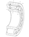
図1および図2に示す実施の形態はNJタイプの円筒ころ軸受に適用した例であり、この円筒ころ軸受は、内輪2と、外輪4と、円筒ころ6と、間座8とで構成されている。内輪は片つば付きで、外輪4は両つば付きである。円筒ころ6は内輪2の軌道面と外輪4の軌道面との間で転動自在で、隣り合う円筒ころ6間に間座8が介在させてある。間座8は概ね板状で、その両面に円筒ころ6の転動面6aと接触する面すなわちころ接触面8aを有する。間座8の長手方向の両端には、円筒ころ6のころ端面6bと向かい合う面をもった拡張部8bが形成してある。
The embodiment shown in FIGS. 1 and 2 is an example applied to an NJ type cylindrical roller bearing, and this cylindrical roller bearing includes an
各拡張部8bは外輪4のつば4aの内径面と向かい合っており、軸受の運転中、間座8は外輪4のつば4aの内径面にて案内される。ここで、図1から分かるとおり、間座8の上面すなわち軸受の半径方向外側の面は、拡張部8bを除き、緩やかな勾配をもつ凹形状に形成されており、間座8の上面の勾配は外輪4のつば4aの内径面の途中の位置から開始している。言い換えれば、間座8の各拡張部8bの長さは外輪4のつば4aの内径面の幅よりも短い。したがって、間座8が、外輪4のつば4aの内径面と内側側面との角部(つば肩部)と接触することはない。なお、この実施の形態では、間座8の上面を凹形状に形成し、この凹部と拡張部の上面とを緩やかな曲線でつないであるが、前記凹形状の底面と拡張部の上面は、勾配ではなく垂直につないでもよい。要するに、間座8の上面のうち、中央部をその両側の拡張部8bよりも一段低くすればよく、両者間の移行部はなだらかであっても、あるいは段差ができていてもよい。
Each
図3に示すように、間座8のころ転動面6aと向き合う面すなわちころ接触面8aはころ6のピッチ円を跨いで延在する凹形状である。間座8が外輪つば内径面によって案内され、隣り合うころ6で間座8を挟み込んだとき、間座8と外輪4との間にすきまSrがある。図4に示すように、外輪4の軌道面上で間座8をころ6で挟み込むと、外輪4のつば内径面の凹形状の底を接触位置として間座8の半径方向位置が決まる。そのとき、間座8と外輪4との間にすきまSrが存在するように設定することで、間座8が隣り合うころ6によって外輪4に押し付けられる状態(図4参照)を回避することができる。すなわち、上記設定により間座8は基本的にはころ案内となり、円周方向すきまに位置する間座8だけが隣り合うころ6の拘束から解放され、回転速度が高い場合には、自重、遠心力以外に半径方向への力が作用しないため、間座8の案内面(外輪つば内径面と向き合う拡張部の上面)における発熱や磨耗を軽減させることができる。
As shown in FIG. 3, the surface of the
図3から分かるように、間座8の案内面(外輪つば内径面と向き合う面)は、外輪つば内径面の曲率半径R2よりも小さい曲率半径R1の凸曲面である。なお、図示は省略したが、間座の拡張部を内輪つば外径側に配置する場合、間座8の内輪つば外径面と向き合う面を、内輪つば外径の曲率半径よりも大きい曲率半径の凹曲面とすることもできる。このような構成を採用することで、いわゆる「くさび効果」(運動方向に狭まっているくさび状のすきまに、流体が粘性によって引き込まれて圧力すなわち負荷能力を発生する効果)が得られ、間座の案内面における発熱や磨耗を軽減させることができる。
As can be seen from FIG. 3, the guide surface of the spacer 8 (the surface facing the inner surface of the outer ring collar) is a convex curved surface having a radius of curvature R1 smaller than the radius of curvature R2 of the inner surface of the outer ring collar. In addition, although illustration was abbreviate | omitted, when arrange | positioning the expansion part of a spacer to an inner ring collar outer diameter side, the curvature radius larger than the curvature radius of the inner ring collar outer diameter is the surface facing the inner ring collar outer diameter surface of the
2 内輪
4 外輪
4a つば
6 円筒ころ
6a 転動面
6b ころ端面
8 間座
8a ころ接触面
8b 拡張部
2
Claims (6)
Priority Applications (1)
| Application Number | Priority Date | Filing Date | Title |
|---|---|---|---|
| JP2006058160A JP4554539B2 (en) | 2006-03-03 | 2006-03-03 | Rolling bearing |
Applications Claiming Priority (1)
| Application Number | Priority Date | Filing Date | Title |
|---|---|---|---|
| JP2006058160A JP4554539B2 (en) | 2006-03-03 | 2006-03-03 | Rolling bearing |
Publications (2)
| Publication Number | Publication Date |
|---|---|
| JP2007232190A true JP2007232190A (en) | 2007-09-13 |
| JP4554539B2 JP4554539B2 (en) | 2010-09-29 |
Family
ID=38552976
Family Applications (1)
| Application Number | Title | Priority Date | Filing Date |
|---|---|---|---|
| JP2006058160A Active JP4554539B2 (en) | 2006-03-03 | 2006-03-03 | Rolling bearing |
Country Status (1)
| Country | Link |
|---|---|
| JP (1) | JP4554539B2 (en) |
Citations (10)
| Publication number | Priority date | Publication date | Assignee | Title |
|---|---|---|---|---|
| JPS5415144U (en) * | 1977-07-02 | 1979-01-31 | ||
| JPS5493646U (en) * | 1977-12-15 | 1979-07-03 | ||
| JPH0217218A (en) * | 1988-07-05 | 1990-01-22 | Koyo Seiko Co Ltd | Roll bearing |
| JPH0658334A (en) * | 1992-08-07 | 1994-03-01 | Nippon Seiko Kk | Radial bearing to suppress squeak |
| JPH084773A (en) * | 1994-06-21 | 1996-01-09 | Ntn Corp | Solid lubricating rolling bearing |
| JPH09242759A (en) * | 1996-03-11 | 1997-09-16 | Nippon Seiko Kk | Roller bearing |
| JPH1162995A (en) * | 1997-08-28 | 1999-03-05 | Nippon Seiko Kk | Rolling bearing |
| JPH11280769A (en) * | 1998-03-27 | 1999-10-15 | Nippon Seiko Kk | Roller bearing |
| JP2000320548A (en) * | 1999-05-13 | 2000-11-24 | Koyo Seiko Co Ltd | Rolling bearing |
| JP2007232187A (en) * | 2006-03-03 | 2007-09-13 | Ntn Corp | Cylindrical roller bearing for transmission |
-
2006
- 2006-03-03 JP JP2006058160A patent/JP4554539B2/en active Active
Patent Citations (10)
| Publication number | Priority date | Publication date | Assignee | Title |
|---|---|---|---|---|
| JPS5415144U (en) * | 1977-07-02 | 1979-01-31 | ||
| JPS5493646U (en) * | 1977-12-15 | 1979-07-03 | ||
| JPH0217218A (en) * | 1988-07-05 | 1990-01-22 | Koyo Seiko Co Ltd | Roll bearing |
| JPH0658334A (en) * | 1992-08-07 | 1994-03-01 | Nippon Seiko Kk | Radial bearing to suppress squeak |
| JPH084773A (en) * | 1994-06-21 | 1996-01-09 | Ntn Corp | Solid lubricating rolling bearing |
| JPH09242759A (en) * | 1996-03-11 | 1997-09-16 | Nippon Seiko Kk | Roller bearing |
| JPH1162995A (en) * | 1997-08-28 | 1999-03-05 | Nippon Seiko Kk | Rolling bearing |
| JPH11280769A (en) * | 1998-03-27 | 1999-10-15 | Nippon Seiko Kk | Roller bearing |
| JP2000320548A (en) * | 1999-05-13 | 2000-11-24 | Koyo Seiko Co Ltd | Rolling bearing |
| JP2007232187A (en) * | 2006-03-03 | 2007-09-13 | Ntn Corp | Cylindrical roller bearing for transmission |
Also Published As
| Publication number | Publication date |
|---|---|
| JP4554539B2 (en) | 2010-09-29 |
Similar Documents
| Publication | Publication Date | Title |
|---|---|---|
| JPH08296653A (en) | Automatic aligning roller bearing having cage | |
| JP5241115B2 (en) | Needle roller bearing | |
| WO2007069392A1 (en) | Roller bearing | |
| JP2010133560A (en) | Roller bearing equipped with optimized outer ring | |
| JP2007247849A (en) | Cylindrical roller bearing with aligning ring for agitator | |
| JP2007255601A (en) | Double row roller bearing and method for assembling the same | |
| US10001168B2 (en) | Spherical roller bearing arrangement | |
| JP2006300079A (en) | Roller bearing | |
| JP2011094716A (en) | Thrust roller bearing | |
| JP4554539B2 (en) | Rolling bearing | |
| JP2012219994A (en) | Rolling bearing | |
| JP2009079696A (en) | Mechanism for applying preload to rolling bearing | |
| JP2008002495A (en) | Automatic aligning roller bearing | |
| JP2008169936A (en) | Deep-groove ball bearing | |
| JP4497117B2 (en) | Rolling bearing | |
| JP2008064230A (en) | Thrust bearing | |
| JP2006214533A (en) | Thrust cylindrical roller bearing | |
| JP6106830B2 (en) | Rolling bearing and method of using the same | |
| US9541127B1 (en) | Spherical roller bearing | |
| JP4855181B2 (en) | Roller bearing | |
| JP2007162916A (en) | Roller bearing | |
| JP2006183733A (en) | Thrust roller bearing | |
| JP2007247850A (en) | Cylindrical roller bearing with aligning ring for dryer roll | |
| JP5218231B2 (en) | Roller bearing cage, inner ring assembly, outer ring assembly and rolling bearing provided with the cage | |
| JP4745085B2 (en) | Cylindrical roller bearing for transmission |
Legal Events
| Date | Code | Title | Description |
|---|---|---|---|
| A621 | Written request for application examination |
Free format text: JAPANESE INTERMEDIATE CODE: A621 Effective date: 20090205 |
|
| RD04 | Notification of resignation of power of attorney |
Free format text: JAPANESE INTERMEDIATE CODE: A7424 Effective date: 20091105 |
|
| A977 | Report on retrieval |
Free format text: JAPANESE INTERMEDIATE CODE: A971007 Effective date: 20100324 |
|
| A131 | Notification of reasons for refusal |
Free format text: JAPANESE INTERMEDIATE CODE: A131 Effective date: 20100331 |
|
| A521 | Request for written amendment filed |
Free format text: JAPANESE INTERMEDIATE CODE: A523 Effective date: 20100528 |
|
| TRDD | Decision of grant or rejection written | ||
| A01 | Written decision to grant a patent or to grant a registration (utility model) |
Free format text: JAPANESE INTERMEDIATE CODE: A01 Effective date: 20100630 |
|
| A01 | Written decision to grant a patent or to grant a registration (utility model) |
Free format text: JAPANESE INTERMEDIATE CODE: A01 |
|
| A61 | First payment of annual fees (during grant procedure) |
Free format text: JAPANESE INTERMEDIATE CODE: A61 Effective date: 20100714 |
|
| FPAY | Renewal fee payment (event date is renewal date of database) |
Free format text: PAYMENT UNTIL: 20130723 Year of fee payment: 3 |
|
| R150 | Certificate of patent or registration of utility model |
Ref document number: 4554539 Country of ref document: JP Free format text: JAPANESE INTERMEDIATE CODE: R150 Free format text: JAPANESE INTERMEDIATE CODE: R150 |
|
| FPAY | Renewal fee payment (event date is renewal date of database) |
Free format text: PAYMENT UNTIL: 20130723 Year of fee payment: 3 |
|
| FPAY | Renewal fee payment (event date is renewal date of database) |
Free format text: PAYMENT UNTIL: 20130723 Year of fee payment: 3 |
|
| R157 | Certificate of patent or utility model (correction) |
Free format text: JAPANESE INTERMEDIATE CODE: R157 |
|
| R250 | Receipt of annual fees |
Free format text: JAPANESE INTERMEDIATE CODE: R250 |
|
| R250 | Receipt of annual fees |
Free format text: JAPANESE INTERMEDIATE CODE: R250 |
|
| R250 | Receipt of annual fees |
Free format text: JAPANESE INTERMEDIATE CODE: R250 |
|
| R250 | Receipt of annual fees |
Free format text: JAPANESE INTERMEDIATE CODE: R250 |
|
| R250 | Receipt of annual fees |
Free format text: JAPANESE INTERMEDIATE CODE: R250 |
|
| R250 | Receipt of annual fees |
Free format text: JAPANESE INTERMEDIATE CODE: R250 |
|
| R250 | Receipt of annual fees |
Free format text: JAPANESE INTERMEDIATE CODE: R250 |
|
| R250 | Receipt of annual fees |
Free format text: JAPANESE INTERMEDIATE CODE: R250 |
|
| R250 | Receipt of annual fees |
Free format text: JAPANESE INTERMEDIATE CODE: R250 |
|
| R250 | Receipt of annual fees |
Free format text: JAPANESE INTERMEDIATE CODE: R250 |
|
| R250 | Receipt of annual fees |
Free format text: JAPANESE INTERMEDIATE CODE: R250 |