JP2007229648A - Spin coat apparatus for lens - Google Patents
Spin coat apparatus for lens Download PDFInfo
- Publication number
- JP2007229648A JP2007229648A JP2006055878A JP2006055878A JP2007229648A JP 2007229648 A JP2007229648 A JP 2007229648A JP 2006055878 A JP2006055878 A JP 2006055878A JP 2006055878 A JP2006055878 A JP 2006055878A JP 2007229648 A JP2007229648 A JP 2007229648A
- Authority
- JP
- Japan
- Prior art keywords
- lens
- spin
- holding table
- coating
- liquid
- Prior art date
- Legal status (The legal status is an assumption and is not a legal conclusion. Google has not performed a legal analysis and makes no representation as to the accuracy of the status listed.)
- Withdrawn
Links
Images

Landscapes
- Coating Apparatus (AREA)
- Surface Treatment Of Optical Elements (AREA)
Abstract
Description
本発明は、各種レンズのレンズ面に塗布液を塗布処理するスピンコート装置に関する。 The present invention relates to a spin coater that applies a coating solution to lens surfaces of various lenses.
一般的に、コーティングは、被塗布物を保護し、かつ被塗布物に外観性能を与える方法として、また、被塗布物に高機能をもたらして高付加価値を与える方法として、様々な産業分野に用いられている。
光学関連分野、例えば、レンズ製造業においては、レンズの表面に種々のコーティング加工を施し、性能、機能の向上を図ることが一般に行われている。また、近年、レンズとして、成形性、加工性に優れかつ軽量で、しかも割れ難いことから、プラスチックレンズが急速に普及し、各種機器に多用されている。特に、プラスチック眼鏡レンズの場合には、レンズの表面にプライマー加工、ハードコート加工、反射防止加工などの種々のコーティング加工が施されて用いられる。
In general, coating is applied to various industrial fields as a method for protecting an object to be coated and imparting appearance performance to the object to be coated, and as a method for providing a high function to the object to be coated with high added value. It is used.
In the field of optics, for example, in the lens manufacturing industry, it is a common practice to improve the performance and function by applying various coating processes to the lens surface. In recent years, plastic lenses have been rapidly spread and widely used in various devices because they are excellent in moldability and processability, are lightweight, and are difficult to break. In particular, in the case of a plastic spectacle lens, the surface of the lens is used after being subjected to various coating processes such as a primer process, a hard coat process, and an antireflection process.
なお、プライマー加工とは、プラスチック眼鏡レンズ基材とハードコート膜との密着性向上、耐衝撃性向上などの機能を付与する加工であり、一般的には、プライマー用組成物をプラスチック眼鏡レンズ表面に塗布した後、加熱硬化処理することにより行う。
また、ハードコート加工とは、プラスチック眼鏡レンズ表面の耐久性向上、反射防止膜との密着性向上などの機能を付与する加工であり、一般的には、ハードコーティング用組成物をプラスチック眼鏡レンズ表面に塗布した後、加熱硬化処理することにより行う。
さらに、反射防止加工とは、プラスチック眼鏡レンズの表面反射を防ぎ、光学系の透過率の低下や結像に寄与しない光の増加、像のコントラストの低下を防ぐ機能を付与する加工である。この反射防止加工は、プラスチック眼鏡レンズ基材に直接形成されたハードコート層上、あるいはプラスチック眼鏡レンズ基材にプライマー層を介して形成されたハードコート層上に、反射防止膜用組成物を塗布した後に、硬化処理することにより行う。
The primer processing is processing for imparting functions such as improving adhesion between the plastic spectacle lens substrate and the hard coat film and improving impact resistance. Generally, the primer composition is applied to the surface of the plastic spectacle lens. After the coating, a heat curing treatment is performed.
Hard coat processing is processing that provides functions such as improving the durability of the plastic spectacle lens surface and improving adhesion to the antireflection film. Generally, a hard coating composition is applied to the surface of the plastic spectacle lens. After the coating, a heat curing treatment is performed.
Furthermore, the antireflection processing is processing that prevents the surface reflection of the plastic spectacle lens and prevents the decrease in the transmittance of the optical system, the increase in light that does not contribute to the image formation, and the decrease in the contrast of the image. This antireflection treatment is performed by applying an antireflection film composition on a hard coat layer formed directly on a plastic spectacle lens substrate or on a hard coat layer formed on a plastic spectacle lens substrate via a primer layer. Then, it is performed by performing a curing treatment.
こうしたプライマー加工、ハードコート加工、反射防止加工などのコーティング加工には、スピンコート法が好ましく用いられる。スピンコート法は、スピンコート装置の回転テーブル上に保持され、回転するプラスチック眼鏡レンズの表面に、塗布液としてのコーティング用組成物を吐出し、コーティング膜を形成する。スピンコート法によるコーティング膜の形成は、プラスチック眼鏡レンズの表面全体にわたって均一な膜が得られる上に、加工スピードが速いこともあり、広く用いられている。 A spin coating method is preferably used for such coating processing such as primer processing, hard coating processing, and antireflection processing. In the spin coating method, a coating composition as a coating solution is discharged onto the surface of a rotating plastic spectacle lens that is held on a rotating table of a spin coating apparatus to form a coating film. The formation of a coating film by spin coating is widely used because a uniform film can be obtained over the entire surface of the plastic spectacle lens and the processing speed can be high.
しかし、スピンコート装置を用いてレンズの表面にコーティング膜を形成する際、回転するレンズの表面に吐出された塗布液の余剰分が、回転遠心力によりレンズの外周方向に向かって放射状に飛散する。そして、飛散した塗布液がスピンカップの壁面に衝突してミスト化し、レンズの表面に付着したり、あるいはスピンカップの壁面に付着した塗布液が乾燥して粉塵化し、レンズの表面に付着することによる外観不良の発生を防ぐことが難しかった。
こうした課題に対応するために、上面に試料を載せて垂直軸回りに高速回転するスピンヘッド(回転テーブルと同じ)と、スピンヘッドの周囲を覆う薬液飛散防止カップ(スピンカップと同じ)を備え、スピンヘッド上に浮遊する薬液ミストを含む空気を排出する排気口が、スピンヘッド上方の薬液飛散防止カップの壁面に設けられたスピンコータが開示されている(例えば、特許文献1参照)。
However, when a coating film is formed on the surface of the lens using a spin coater, the surplus of the coating liquid discharged on the surface of the rotating lens is scattered radially toward the outer periphery of the lens by the rotational centrifugal force. . The scattered coating liquid collides with the wall surface of the spin cup to become mist and adheres to the surface of the lens, or the coating liquid adhered to the wall surface of the spin cup dries and becomes dust and adheres to the surface of the lens. It was difficult to prevent the appearance failure due to.
In order to cope with such problems, a spin head (same as the rotary table) that rotates the sample around the vertical axis with a sample placed on the upper surface, and a chemical splash prevention cup (same as the spin cup) that covers the periphery of the spin head are provided. A spin coater is disclosed in which an exhaust port for discharging air containing chemical mist floating on the spin head is provided on the wall surface of the chemical splash prevention cup above the spin head (see, for example, Patent Document 1).
しかしながら、レンズのレンズ面に塗布液をスピンコートする場合には、特許文献1に示されるような半導体ウェハ、あるいは光ディスク等の平板状の被塗布物と異なり、曲面を有するレンズ面に対応した塗布液の処理が求められる。特に眼鏡レンズにおいては、レンズ面に凸面と凹面を有するメニスカスレンズが一般的であり、しかも処方によりレンズ面の曲率が多種多様である。
本発明は、こうした課題に鑑みて、レンズのスピンコート法による塗布液の塗布処理において、多様なレンズのレンズ面形状に対応し、好適な塗膜を形成することが可能なレンズのスピンコート装置を提供することを目的とする。
However, when spin-coating a coating solution onto the lens surface of a lens, unlike a semiconductor wafer or optical disk or other flat coated object as disclosed in Patent Document 1, the coating is applied to a lens surface having a curved surface. Liquid processing is required. Particularly in spectacle lenses, a meniscus lens having a convex surface and a concave surface on the lens surface is common, and the curvature of the lens surface varies depending on the prescription.
In view of these problems, the present invention provides a lens spin coat apparatus that can form a suitable coating film corresponding to various lens surface shapes in a coating process of a coating liquid by a spin coating method of a lens. The purpose is to provide.
前記した目的を達成するために、本発明のレンズのスピンコート装置は、スピンコート法にてレンズに塗布処理を施すスピンコート装置であって、上面に前記レンズを載置して垂直軸回りに回転する回転保持台と、前記回転保持台の周囲を覆うスピンカップと、前記レンズに塗布液を吐出する吐出部と、を備え、前記スピンカップの側壁に、回転する前記レンズから振り切られた前記塗布液を回収する開口部が設けられていることを特徴とする。 In order to achieve the above-described object, a spin coating apparatus for a lens according to the present invention is a spin coating apparatus that performs a coating process on a lens by a spin coating method, and the lens is placed on an upper surface around a vertical axis. A rotation holding table that rotates, a spin cup that covers the periphery of the rotation holding table, and a discharge unit that discharges a coating liquid to the lens, and the side wall of the spin cup is shaken off from the rotating lens. An opening for collecting the coating liquid is provided.
この構成によれば、スピンコート法にてレンズのレンズ面に塗布処理を施す際に、回転保持台の周囲を覆うスピンカップの側壁に塗布液を回収する開口部が設けられていることにより、回転保持台に載置されて回転するレンズのレンズ面上に、吐出部から吐出されレンズ面上から振り切られた塗布液が、開口部から回収される。これにより、レンズ面上から振り切られた塗布液が、スピンカップの側壁に衝突して飛散することを防ぎ、飛散した塗布液による外観不良を抑制した好適な塗膜の形成を可能にするスピンコート装置が得られる。 According to this configuration, when the coating process is performed on the lens surface of the lens by the spin coating method, an opening for collecting the coating liquid is provided on the side wall of the spin cup that covers the periphery of the rotation holding table. The coating liquid discharged from the discharge unit and shaken off from the lens surface is collected from the opening on the lens surface of the lens that is mounted on the rotation holding table and rotates. This prevents the coating liquid shaken off from the lens surface from colliding with the side wall of the spin cup and scattering, and enables the formation of a suitable coating film that suppresses appearance defects due to the scattered coating liquid. A device is obtained.
本発明のレンズのスピンコート装置は、回転する前記レンズから振り切られた前記塗布液の前記スピンカップ側壁への到達位置が前記開口部位置となるよう、前記スピンカップと前記回転保持台とを、前記レンズのレンズ面形状および前記レンズを回転させる際の回転数に基づき、前記回転保持台の垂直軸方向に相対移動することを特徴とする。 In the spin coating apparatus for a lens of the present invention, the spin cup and the rotation holding table are arranged so that the position where the coating liquid shaken off from the rotating lens reaches the spin cup side wall is the opening position. Based on the lens surface shape of the lens and the number of rotations when the lens is rotated, the rotation holder is relatively moved in the vertical axis direction.
この構成によれば、側壁に塗布液を回収する開口部が設けられた回転保持台の周囲を覆うスピンカップと、レンズ面に塗布処理を施すレンズが載置された回転保持台とが、回転保持台の垂直軸方向に相対移動することにより、曲率の異なる多様なレンズ面形状に対応し、回転するレンズ面上から振り切られた塗布液が、スピンカップの側壁に衝突して飛散することを防ぎ、飛散した塗布液による外観不良を抑制した好適な塗膜の形成を可能にするスピンコート装置が得られる。 According to this configuration, the spin cup that covers the periphery of the rotation holding table provided with the opening for collecting the coating liquid on the side wall, and the rotation holding table on which the lens that performs the coating process on the lens surface is rotated. Relative movement in the vertical axis direction of the holding base supports various lens surface shapes with different curvatures, and the coating liquid shaken off from the rotating lens surface collides with the side wall of the spin cup and scatters. It is possible to obtain a spin coat apparatus that can prevent the appearance defect caused by the scattered coating liquid and can form a suitable coating film.
本発明のレンズのスピンコート装置は、前記回転保持台の垂直軸方向に沿って、前記開口部を挟んだ前記スピンカップ側壁の上下面にそれぞれ前記塗布液を検出する一対の検出センサを、さらに備え、前記一対の検出センサが前記回転するレンズから振り切られた塗布液の付着を検出したとき、前記スピンカップと前記回転保持台とを前記回転保持台の垂直軸方向に相対移動する位置補正が行われることを特徴とする。 The lens spin coating apparatus according to the present invention further includes a pair of detection sensors for detecting the coating liquid on the upper and lower surfaces of the spin cup side wall across the opening along the vertical axis direction of the rotation holding table. And when the pair of detection sensors detect the adhesion of the coating liquid shaken off from the rotating lens, the position correction is performed such that the spin cup and the rotation holding table are relatively moved in the vertical axis direction of the rotation holding table. It is performed.
この構成によれば、スピンカップの側壁に設けられた塗布液を回収する開口部を挟んだ回転保持台の垂直軸方向に、塗布液を検出する一対の検出センサを備え、一対の検出センサが検出値の変化を検出したときに、レンズ面に塗布処理を施すレンズが載置された回転保持台とスピンカップとが、回転保持台の垂直軸方向に相対移動する位置補正が行われる。これにより、回転するレンズ面上から振り切られる塗布液が、スピンコート装置に入力する塗布処理条件等の入力情報の誤入力や、塗布液の粘度上昇の発生等により、開口部の停止位置、あるいは回転保持台の停止位置がズレた場合であっても、所定の位置に位置補正されて、塗布液がスピンカップの側壁に衝突して飛散することを防ぎ、飛散した塗布液による外観不良を抑制した好適な塗膜の形成を可能にするスピンコート装置が得られる。 According to this configuration, the pair of detection sensors includes the pair of detection sensors that detect the coating liquid in the vertical axis direction of the rotation holding table sandwiching the opening that collects the coating liquid provided on the side wall of the spin cup. When a change in the detection value is detected, position correction is performed in which the rotation holding table and the spin cup on which the lens to be coated is placed on the lens surface are relatively moved in the vertical axis direction of the rotation holding table. As a result, the coating liquid shaken off from the rotating lens surface is stopped by the stop position of the opening due to an erroneous input of input information such as coating processing conditions input to the spin coat apparatus, or an increase in the viscosity of the coating liquid. Even if the stop position of the rotary holding base is shifted, the position is corrected to a predetermined position to prevent the coating liquid from colliding with the side wall of the spin cup and scattering, and suppressing appearance defects due to the scattered coating liquid Thus, a spin coat apparatus that can form a suitable coating film can be obtained.
先ず、本発明に係わるスピンコート装置の構成を、図面に基づいて説明する。
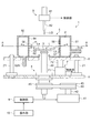
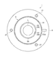
図1は、レンズの凹面に塗布液をスピンコートする態様を示す本発明のスピンコート装置の側面模式図であり、図2は、図1におけるスピンコート装置のA−A線に沿った断面の矢視図である。
First, the configuration of the spin coater according to the present invention will be described with reference to the drawings.
FIG. 1 is a schematic side view of a spin coater of the present invention showing a mode in which a coating solution is spin-coated on a concave surface of a lens, and FIG. 2 is a cross-sectional view taken along line AA of the spin coater in FIG. It is an arrow view.
図1および図2において、スピンコート装置1は、スピンコート法にて、プラスチック眼鏡レンズLに塗布処理を施す装置である。このスピンコート装置1は、基台2と、眼鏡レンズLを保持する回転保持台3と、回転保持台3を回転する回転機構4と、回転保持台3を収容する円筒形のスピンカップ5と、スピンカップ5を保持固定する昇降台6と、昇降台6(スピンカップ5)を昇降する昇降ユニット7と、塗布液を吐出する吐出部8と、制御部9と、操作部10を備えている。
1 and 2, a spin coat apparatus 1 is an apparatus that performs a coating process on a plastic spectacle lens L by a spin coat method. The spin coat apparatus 1 includes a
基台2は、例えば円形状を成し、基台2の上方に配設された円筒形のスピンカップ5の外周を取り囲む位置に、三本の案内軸21が軸止されている。この三本の案内軸21は、円形状を3等分する中心角上の中心から略等距離の位置に配設されている。また、基台2の中心部に回転機構4が取付られ、回転機構4と三本の案内軸21との間の基台2の上面に、昇降ユニット7が着設されている。
The
回転保持台3は、基台2に対して略水平に配設された円筒状の保持台であり、円筒状の略中心が回転機構4の回転軸46の中心軸上に連結され、回転軸46の回転とともに回転する。この回転保持台3上には、ハードコート液LQがスピンコートされる眼鏡レンズLが載置され、眼鏡レンズLを保持する真空チャック機能を有する。また、回転保持台3は、スピンカップ5内に配設されている。なお、図1および図2において、回転保持台3上には、後述するスピンコートされる眼鏡レンズLが、一方のレンズ面である凹面Laを吐出部8側にして載置され、保持された態様を示す。
The rotation holding table 3 is a cylindrical holding table arranged substantially horizontally with respect to the
回転機構4は、スピンドルモータ41と、このスピンドルモータ41の駆動軸42と、この駆動軸42における外周面の略中央に一体的に設けられた略円筒状の第1のプーリー43と、この第1のプーリー43の外周面に掛け回されたタイミングベルト44と、第1のプーリー43と隣接して設けられ外周面にタイミングベルト44が掛け回された略円筒状の第2のプーリー45と、この第2のプーリー45の内周面に一体的に設けられ一端側が回転保持台3の下部に連結された回転軸46とを備えている。
The
回転軸46は、第2のプーリー45を基台2の下面側にして、基台2の鉛直方向の上方に延伸し、軸受け等を介して基台2に回転可能に取り付けられている。また、回転軸46には、その中心軸に沿って図示しない真空吸引装置に接続する吸引管が配設されている。なお、スピンドルモータ41の回転駆動は、制御部9の制御信号に基づいて行われる。
The
スピンカップ5は、カップ内に回転機構4の回転軸46に連結された回転保持台3を収容し、スピンコートする際に発生する余剰分の塗布液を処理するための容器であり、円筒形の側板部51と、底板部52と、円筒形の側壁53,54と、上板部55と、液体検出センサ57,58を含み構成され、底板部52の底面が昇降台6の上面に固定されている。
また、円筒形の側板部51の側面には、排気ファンに接続する排気管51Aが設けられている。底板部52は、円筒形の側板部51の下端面に接続固定され、円形形状の中心部に上下に貫通する孔を有し、この孔に回転軸46が挿通されている。
The
Further, an
円筒形の側壁53,54は、略同一内径の円筒形からなり、眼鏡レンズLの回転保持台3への取り付けおよび取り外しが可能な内径を有し、円筒形の略中心を円筒形の側板部51の略中心にして、側板部51の内側に、回転保持台3の周囲を覆うように設けられている。
The
この円筒形の側壁53は底板部52と接続固定されている。一方、円筒形の側壁54は上板部55と接続固定され、側壁53の円筒形の上端面と側壁54の円筒形の下端面とが所定間隔離れた所定の幅αから成る開口部56が形成されている。すなわち、この円筒形の側壁53,54は、スピンカップ5のインナーカップとして構成されている。
なお、開口部56の所定の幅αについては、図3に基づいて後述する。
The
The predetermined width α of the
また、開口部56を形成する側壁53および側壁54の回転保持台3(回転軸46)側には、回転保持台3の垂直軸方向に開口部56を挟む位置に一対の液体検出センサ57,58が着設されている。各液体検出センサ57,58の回転保持台3の垂直軸方向における大きさは、前記開口部56の所定の幅α程度である。
液体検出センサ57,58は、例えば、静電容量型センサであり、センサ表面における検出値(静電容量値)の変化を検出し、その検出信号は制御部9に出力される。
Further, a pair of
The
円筒形の側板部51、底板部52、上板部55および円筒形の側壁53,54から形成される回転体形状の領域βは、スピンコートする際に発生する余剰分の塗布液の排液容器、および余剰分の塗布液のミストを含む空気の排気ダクトとしての機能を有し、底板部52には、収容容器に接続する排液管52Aが設けられている。
このように構成されたスピンカップ5は、昇降台6の上面に着設されている。
A rotating body-shaped region β formed by the cylindrical
The
昇降台6は、中心部に上下に貫通する孔と、基台2に軸止された三本の案内軸21に軸通する案内孔を有する。中心部に上下に貫通する孔に回転軸46が挿通されている。
昇降ユニット7は油圧シリンダであり、制御部9の制御信号に基づいて油圧ポンプ71が作動することにより、ロッド72が伸縮して、昇降台6が回転機構4の回転軸46の軸方向に沿う鉛直方向に昇降する。すなわち、昇降台6に着設されたスピンカップ5が、回転機構4の回転軸46の軸方向に沿って昇降する。
The
The elevating
吐出部8は、吐出バルブ81、吐出ノズル82を備え、回転保持台3に載置された眼鏡レンズLの被塗布面(上面)へ向けて、回転保持台3の上方からハードコート液LQを吐出する装置である。吐出バルブ81は、制御部9の制御信号に基づいて作動し、配管を介して容器タンク(図示せず)内のハードコート液LQを吐出ノズル82から吐出する。この吐出ノズル82からハードコート液LQを吐出する際は、吐出ノズル82の位置と回転する眼鏡レンズLの中心(駆動軸42の中心)とを略一致させることが好ましい。
The
制御部9は、回転機構4のスピンドルモータ41、吐出バルブ81、昇降ユニット7の油圧ポンプ71の作動を制御する。
操作部10は、塗布処理される眼鏡レンズLの凹面Laおよび凸面Lbの曲率および外径等のレンズ形状情報、塗布処理に用いる塗布液の種類および塗布時間、回転機構4の回転数および回転時間等の塗布処理条件を入力する入力手段であり、これらの塗布処理条件は、塗布処理前に予め操作部10から入力され、制御部9に格納される。
The
The
次に、以上のように構成されたスピンコート装置1を用いて、眼鏡レンズLのレンズ面にハードコート液LQを塗布処理するスピンコート方法について説明する。 Next, a spin coating method in which the hard coat liquid LQ is applied to the lens surface of the spectacle lens L using the spin coat apparatus 1 configured as described above will be described.
図1において、回転保持台3に載置され、ハードコート液LQが塗布処理される眼鏡レンズLは、重合性組成物を硬化した透明樹脂からなり、レンズ面の一方の面が凹面La、他方の面が凸面Lbからなるメニスカスレンズである。
なお、本実施形態における眼鏡レンズLは、眼鏡フレームに枠入れ加工(いわゆる玉型加工)される前のレンズであり、平面が75mm程度の略円形形状を成している。また、この眼鏡レンズLのレンズ面(凹面Laおよび凸面Lb)には、前工程において予めプライマー膜が形成されている。
In FIG. 1, a spectacle lens L placed on the rotation holding table 3 and coated with the hard coat liquid LQ is made of a transparent resin obtained by curing a polymerizable composition, and one surface of the lens surface is a concave surface La, and the other surface Is a meniscus lens having a convex surface Lb.
The spectacle lens L in the present embodiment is a lens before frame processing (so-called lens processing) on the spectacle frame, and has a substantially circular shape with a plane of about 75 mm. In addition, a primer film is formed in advance on the lens surface (concave surface La and convex surface Lb) of the spectacle lens L in the previous step.
プライマー膜は、スピンコート法の他に、ディッピング法、スピンナー法、ロールコート法、スプレー法、インクジェット法あるいはフロー法により、ウレタン樹脂などで形成され、眼鏡レンズLの基材とハードコート膜との密着性を高める必要がある場合や、耐衝撃性を向上させる必要がある場合に形成されるものである。 The primer film is formed of urethane resin or the like by a dipping method, a spinner method, a roll coating method, a spray method, an ink jet method or a flow method in addition to the spin coating method. It is formed when it is necessary to improve adhesion or when it is necessary to improve impact resistance.
塗布液としてのハードコート液LQは、有機ケイ素化合物を有機溶剤で希釈し、必要に応じて水または薄い塩酸、酢酸等を添加して加水分解を行い、さらに、無機酸化物微粒が有機溶媒中にコロイド状に分散したゾルを添加した後、必要に応じて硬化触媒、界面活性剤、帯電防止剤、紫外線吸収剤、酸化防止剤などを添加し、十分に撹拌して調合された液であり、塗布後に硬化処理されることにより眼鏡レンズLのレンズ面の耐久性が向上する。 The hard coat liquid LQ as a coating liquid is obtained by diluting an organosilicon compound with an organic solvent, adding water or thin hydrochloric acid, acetic acid or the like as necessary to perform hydrolysis, and further, inorganic oxide fine particles in the organic solvent. After adding a colloidally dispersed sol, a curing catalyst, surfactant, antistatic agent, ultraviolet absorber, antioxidant, etc. are added as necessary, and the mixture is prepared with sufficient stirring. The durability of the lens surface of the spectacle lens L is improved by being cured after application.
眼鏡レンズLのハードコート液LQの塗布処理は、眼鏡レンズLの凹面Laと凸面Lbに対して、別々に行われる。
先ず、操作部10から塗布処理される眼鏡レンズLの凹面Laおよび凸面Lbの曲率および外径等のレンズ形状情報、塗布処理に用いる塗布液の種類および塗布時間、回転機構4の回転数および回転時間等の塗布処理条件が入力される。
The coating process of the hard coat liquid LQ for the spectacle lens L is performed separately on the concave surface La and the convex surface Lb of the spectacle lens L.
First, lens shape information such as curvature and outer diameter of the concave surface La and the convex surface Lb of the spectacle lens L to be applied from the
そして、予めプライマー膜が形成された眼鏡レンズLが回転保持台3に取り付けられる。眼鏡レンズLの取り付けは、凸面Lbを回転保持台3側にして、略レンズ中心が回転保持台3の略中心位置にセットされる。そして、真空吸引装置を作動して、真空により眼鏡レンズLが回転保持台3に吸着保持される。これにより、ハードコート液LQの塗布処理が可能な状態になる。 Then, the spectacle lens L on which the primer film is formed in advance is attached to the rotation holding table 3. When the spectacle lens L is attached, the convex surface Lb is set to the rotation holding table 3 side, and the approximate lens center is set to the approximate center position of the rotation holding table 3. Then, by operating the vacuum suction device, the spectacle lens L is sucked and held on the rotation holding table 3 by vacuum. As a result, the hard coat liquid LQ can be applied.
そして、予め操作部10から入力され制御部9に格納された、凹面Laの曲率等の入力情報に基づいて、制御部9から昇降ユニット7に制御信号を出力される。昇降ユニット7に制御信号が入力されると、油圧ポンプ71が作動してロッド72が伸縮し、昇降台6および昇降台6に固着されたスピンカップ5が、回転機構4の回転軸46の軸方向に沿って昇降し、所定の位置に停止する。スピンカップ5が停止する所定の位置は、図1中に矢印aで示す線が、スピンカップ5の側壁53と側壁54との間に形成された開口部56の幅αの中心位置とが、略一致する位置である。所定の位置の詳細な説明は、図3に基づいて後述する。
なお、昇降台6および昇降台6に着設されたスピンカップ5の昇降の際には、昇降台6に連動してハードコート液LQを吐出する吐出部8が昇降するのが望ましい。
A control signal is output from the
In addition, when raising and lowering the
そして、眼鏡レンズLが吸着保持された回転保持台3は、制御部9の制御信号に基づいてスピンドルモータ41が回転駆動する。スピンドルモータ41が回転駆動すると、駆動軸42(第1のプーリー43)、タイミングベルト44、回転軸46(第2のプーリー45)を介して、回転保持台3が回転する。すなわち、回転保持台3に取り付けられた眼鏡レンズLが回転する。回転保持台3の回転数は、低速回転としての略800rpmである。
The
そして、吐出部8の吐出バルブ81が制御部9の制御信号に基づいて作動し、吐出ノズル82から眼鏡レンズLの凹面La上に、ハードコート液LQが2cc程度吐出される。
そして、回転保持台3を低速回転(略800rpm)状態で所定時間保持した後に、制御部9の制御信号に基づいてスピンドルモータ41の回転が制御され、回転保持台3の回転数が略800rpmから高速回転としての略1800rpmに移行し、高速回転を15秒間程度保持した後に、スピンドルモータ41の回転を停止する。
Then, the
Then, after holding the rotation holding table 3 in a low-speed rotation (approximately 800 rpm) state for a predetermined time, the rotation of the
回転する眼鏡レンズLの凹面Laの略中心上に吐出されたハードコート液LQは、回転する眼鏡レンズLの遠心力で凹面に万遍なく広がる。そして、回転保持台3の回転数が高速回転に移行することにより、余剰のハードコート液LQが、遠心力で眼鏡レンズLの凹面La上からスピンカップ5の側壁53,54の方向に向かって放射状に振り切られるとともに、凹面La上に所定の膜厚の塗膜が略均一に形成される。
The hard coat liquid LQ discharged on the approximate center of the concave surface La of the rotating spectacle lens L spreads uniformly on the concave surface by the centrifugal force of the rotating spectacle lens L. Then, when the rotation speed of the rotation holding table 3 shifts to high speed rotation, the excessive hard coat liquid LQ is moved from the concave surface La of the spectacle lens L toward the
凹面La上に塗布されるハードコート液LQの膜厚は、ハードコート液LQの吐出終了時点から経過する低速回転の保持時間により制御される。本実施形態の場合には、低速回転を略2秒間保持することにより、膜厚が略2μmの塗膜が形成される。
一方、眼鏡レンズLの凹面La上からスピンカップ5の側壁53,54の方向に向かって放射状に振り切られた余剰のハードコート液LQは、スピンカップ5の円筒形の側壁53と側壁54との間に形成された開口部56から回収され、回転体形状の領域βに収容される。
The film thickness of the hard coat liquid LQ applied on the concave surface La is controlled by the low-speed rotation holding time that elapses from the end of the discharge of the hard coat liquid LQ. In the case of the present embodiment, a coating film having a film thickness of about 2 μm is formed by holding the low speed rotation for about 2 seconds.
On the other hand, the excessive hard coat liquid LQ that has been swung radially from the concave surface La of the spectacle lens L toward the
ここで、図3を参照しながら、放射状に振り切られる余剰のハードコート液LQについて説明する。併せて、スピンカップ5が昇降して停止する所定の位置、および開口部56の幅αについても説明する。
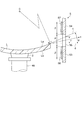
図3は、本発明のスピンコート装置1の開口部56周辺の部分説明図である。
Here, with reference to FIG. 3, the excessive hard coat liquid LQ that is shaken off radially will be described. In addition, a predetermined position where the
FIG. 3 is a partial explanatory view around the
図3において、回転する眼鏡レンズLの凹面La上からスピンカップ5の側壁53,54の方向に向かって放射状に振り切られる余剰のハードコート液LQの方向は、眼鏡レンズLの凹面Laを形成する曲面(中心0)における眼鏡レンズLの外形位置eを接点とする接線cと、眼鏡レンズLの外形位置eにおける水平線dとの挟角θにおける略θ/2方向a(図1中に示す矢印aと同じ)である。
この放射状に振り切られる余剰のハードコート液LQの矢印a方向は、回転する眼鏡レンズLの回転数が1800rpm程度における場合であって、回転数が高くなるに従って水平線dの方向に近づく。
In FIG. 3, the direction of the excess hard coat liquid LQ that is swayed radially from the concave surface La of the rotating spectacle lens L toward the
The arrow a direction of the excessive hard coat liquid LQ shaken off radially is when the rotating eyeglass lens L has a rotational speed of about 1800 rpm, and approaches the direction of the horizontal line d as the rotational speed increases.
スピンカップ5の側壁53と側壁54との間に形成された開口部56の幅αは、少なくとも接線cと水平線dが、側壁53,54の領域β(図1参照)側の面に延伸する垂直線と交わる辺の幅γよりも大きく設定される。また、開口部56の幅αは、用いる塗布液の粘度、塗布液が塗布される眼鏡レンズの最大外径や最小曲率等を考慮して適宜設定される。
The width α of the
昇降台6および昇降台6に固着されたスピンカップ5が停止する所定の位置は、開口部56の幅αの回転保持台3(回転軸46)の垂直軸方向における2分割中心線が、上記辺の幅γの垂直軸方向における略2分割中心点と一致する位置である。
The predetermined position at which the
そして、回転する眼鏡レンズLの凹面La上から放射状に振り切られて、スピンカップ5の開口部56から回収され、回転体形状の領域βに収容されたハードコート液LQは、一部が側板部51に衝突して跳ね返りミスト化する。そして、一部は液状の状態で収容される。
ハードコート液LQのミストは、側板部51の側面に設けられ、排気ファンに接続する排気管51Aから、空気と共に収容容器(図示せず)内に収容される。また、液状のハードコート液LQは、底板部52に配設された排液管52Aに流入して、別の収容容器(図示せず)内に収容される。
Then, the hard coat liquid LQ that is radially swung from the concave surface La of the rotating spectacle lens L, collected from the
The mist of the hard coat liquid LQ is provided on the side surface of the
こうした塗布処理の際に、回転する眼鏡レンズLの凹面La上から振り切られた余剰のハードコート液LQが、スピンカップ5の開口部56から回収されずに、側壁53あるいは側壁54に衝突した場合には、昇降台6および昇降台6に着設されたスピンカップ5を昇降する位置補正が行われる。すなわち、スピンカップ5と回転保持台3(眼鏡レンズL)とが相対移動する位置補正が行われる。
In such a coating process, when excessive hard coat liquid LQ shaken off from the concave surface La of the rotating spectacle lens L collides with the
凹面La上から振り切られた余剰のハードコート液LQが、側壁53あるいは側壁54に衝突すると、開口部56を挟む垂直方向に着設された液体検出センサ57あるいは液体検出センサ58のセンサ面に、ハードコート液LQが飛散する。センサ面にハードコート液LQが飛散すると、検出値(静電容量値)の変化が検出されて、その検出信号が制御部9に出力される。
When the excessive hard coat liquid LQ shaken off from the concave surface La collides with the
検出信号が液体検出センサ57から入力された場合には、制御部9の制御信号に基づいて昇降ユニット7の油圧ポンプ71が作動し、ロッド72が縮んで、昇降台6および昇降台6に着設されたスピンカップ5が、回転軸46の軸方向に沿って所定の距離、下降して停止する。下降する所定の距離は、開口部56の幅α程度である。これにより、凹面La上から振り切られた余剰のハードコート液LQが、スピンカップ5の開口部56から回収され、回転体形状の領域βに収容される。
When the detection signal is input from the
一方、検出信号が液体検出センサ58から入力された場合には、制御部9の制御信号に基づいて昇降ユニット7の油圧ポンプ71が作動し、ロッド72が伸びて、昇降台6および昇降台6に着設されたスピンカップ5が、回転軸46の軸方向に沿って所定の距離、上昇して停止する。上昇する所定の距離は、下降の場合と同様に、開口部56の幅α程度である。
On the other hand, when the detection signal is input from the
回転する眼鏡レンズLの凹面La上から振り切られた余剰のハードコート液LQが、スピンカップ5の開口部56から回収されずに、側壁53あるいは側壁54に衝突する場面は、レンズ面の曲率、回転保持台3の回転数あるいは塗布液の入力情報の誤入力、塗布液の粘度上昇等の場合に発生する。
The excessive hard coat liquid LQ swung off from the concave surface La of the rotating spectacle lens L does not collect from the
このようにしてハードコート液LQの塗膜が形成された眼鏡レンズLは、回転保持台3から取り外された後に、略100℃の温度環境で10分間程度加熱され、塗膜の仮焼成(仮硬化処理)が行われる。 The eyeglass lens L on which the coating film of the hard coating liquid LQ is formed in this way is removed from the rotary holding table 3 and then heated for about 10 minutes in a temperature environment of approximately 100 ° C. Curing process).
そして、仮焼成された眼鏡レンズLは、スピンコート装置1の回転保持台3に載置され、もう一方のレンズ面である凸面Lbに、ハードコート液LQの塗布処理が行われる。
凸面Lbへのハードコート液LQの塗布処理について、図4を参照しながら説明する。なお、凸面Lbの塗布処理、および仮焼成方法は、眼鏡レンズLを回転保持台3に保持した後に、スピンカップ5を所定の位置に移動すること以外は、凹面Laの場合と同様であり、詳細な説明は適宜省略する。
Then, the preliminarily fired spectacle lens L is placed on the rotation holding table 3 of the spin coater 1, and the hard coat liquid LQ is applied to the convex surface Lb which is the other lens surface.
Application processing of the hard coat liquid LQ to the convex surface Lb will be described with reference to FIG. The convex surface Lb application process and the pre-baking method are the same as in the case of the concave surface La, except that the
図4は、眼鏡レンズLの一方のレンズ面である凸面Lbに、ハードコート液LQをスピンコートする態様を示す本発明のスピンコート装置の側面模式図である。
図4において、眼鏡レンズLの凸面Lbへのハードコート液LQの塗布処理は、ハードコート液LQの塗布および仮焼成処理が行われた凹面Laを回転保持台3側にして、略レンズ中心が回転保持台3の略中心位置にセットされる。そして、真空吸引装置が作動して、真空により眼鏡レンズLが回転保持台3に吸着保持される。
FIG. 4 is a schematic side view of the spin coater of the present invention showing a mode in which the hard coat liquid LQ is spin-coated on the convex surface Lb which is one lens surface of the spectacle lens L.
In FIG. 4, the hard coat liquid LQ is applied to the convex surface Lb of the spectacle lens L with the concave surface La on which the hard coat liquid LQ has been applied and pre-baked being placed on the
そして、制御部9の制御信号に基づいて昇降ユニット7の油圧ポンプ71が作動することにより、ロッド72が縮んで、昇降台6および昇降台6に固着されたスピンカップ5が、基台2に設けられた三本の案内軸21に案内されて、回転軸46の軸方向に沿って下降し、所定の位置に停止する。昇降台6および昇降台6に着設されたスピンカップ5が停止する所定の位置は、凹面Laの場合と同様に、図4中に矢印bで示す線が、スピンカップ5の側壁53と側壁54との間に形成された開口部56の幅α(図3参照)の中心位置とが、略一致する位置である。
Then, when the
そして、スピンドルモータ41が回転駆動し、回転保持台3に取り付けられた眼鏡レンズLが回転するとともに、吐出部8の吐出ノズル82から眼鏡レンズLの凸面Lb上に、ハードコート液LQが吐出され、凹面Laと同様のスピンコート方法により、ハードコート液LQの塗布が行われる。そして、凸面Lbにハードコート液LQの塗布が行われた眼鏡レンズLは、仮焼成が行われる。
Then, the
なお、凸面Lbへのハードコート液LQのスピンコートの際、回転する眼鏡レンズLの凸面Lb上に吐出された余剰のハードコート液LQは、遠心力で凸面Lb上から放射状に、図4中に矢印bで示す方向に振り切られ、スピンカップ5の開口部56から回収され、領域β内に収容される。矢印bで示される方向は、凹面Laの場合と同様に、眼鏡レンズLの凸面Lbを形成する曲面における眼鏡レンズLの外形位置を接点とする接線と、眼鏡レンズLの外形位置における水平線との挟角の略1/2中心角方向である。
In addition, when spin-coating the hard coat liquid LQ onto the convex surface Lb, the excessive hard coat liquid LQ discharged onto the convex surface Lb of the rotating spectacle lens L is radiated from the convex surface Lb radially by centrifugal force in FIG. And is collected from the
なお、眼鏡レンズLの各レンズ面へのハードコート液LQの塗布処理前に、回転保持台3に吸着保持された眼鏡レンズLのレンズ面の純水洗浄を行うのが好ましい。
純水洗浄は、例えば、回転保持台3に吸着保持された眼鏡レンズLを800rpm程度で回転し、図示しないノズルを眼鏡レンズLの中心部から外周部に向かって移動させながら、レンズ面に純水を5cc/sec程度供給する。そして、眼鏡レンズLを略1800rpmで15秒間程度の高速回転に移行して、レンズ面上の純水の振り切りおよび乾燥をして、レンズ面の洗浄を行うことができる。
In addition, before the hard coat liquid LQ is applied to the lens surfaces of the spectacle lens L, it is preferable to clean the lens surface of the spectacle lens L adsorbed and held on the rotation holding table 3 with pure water.
In the pure water cleaning, for example, the spectacle lens L adsorbed and held on the rotation holding table 3 is rotated at about 800 rpm, and a nozzle (not shown) is moved from the central portion of the spectacle lens L toward the outer peripheral portion, while being purely applied to the lens surface. Supply about 5cc / sec of water. Then, the lens surface can be cleaned by shifting the spectacle lens L to a high-speed rotation of approximately 1800 rpm for about 15 seconds, shaking off the pure water on the lens surface, and drying.
この純水洗浄の際にも、スピンカップ5と回転保持台3とが所定の位置に相対移動して、回転する眼鏡レンズLのレンズ面上から振り切られた純水が、スピンカップ5の開口部56から回収され、回転体形状の領域βに収容される。したがって、本実施形態において、純水洗浄に用いられる純水も、塗布液としての機能を有する。
Also during the pure water cleaning, the
以上のように、凹面Laおよび凸面Lbのレンズ面に、ハードコート液LQが塗布され、仮焼成が行われた眼鏡レンズLは、125℃程度の温度環境で1.5時間程度加熱され、スピンコートされたハードコート液LQの本焼成(本硬化処理)が行われる。これにより、眼鏡レンズLのレンズ面にハードコート膜が形成される。 As described above, the spectacle lens L on which the hard coat liquid LQ is applied to the lens surfaces of the concave surface La and the convex surface Lb and pre-baked is heated for about 1.5 hours in a temperature environment of about 125 ° C. The main baking (main curing process) of the coated hard coat liquid LQ is performed. As a result, a hard coat film is formed on the lens surface of the spectacle lens L.
その後、ハードコート膜が形成された眼鏡レンズLは、必要に応じて、ハードコート膜上に、表面反射を防ぐ機能を付与する反射防止膜を形成したり、さらに眼鏡レンズLの最表面に、撥水撥油性能を付与する防汚膜などが形成された後に、眼鏡フレームに枠入れする玉型加工等が行われて、プラスチック眼鏡レンズが完成する。
なお、これらの反射防止膜および防汚膜は、スピンコート装置1を用いたスピンコート法にて各コーティング液を塗布処理した後に、加熱乾燥して形成することができる。スピンコート法の他に、ディッピング法、ロールコート法、スプレー法、インクジェット法あるいはフロー法を用いることもできる。
Thereafter, the spectacle lens L on which the hard coat film is formed, if necessary, on the hard coat film, an antireflection film imparting a function of preventing surface reflection is formed, or further, on the outermost surface of the spectacle lens L, After the antifouling film imparting water and oil repellency performance is formed, a lens shape processing to be put into a spectacle frame is performed, and a plastic spectacle lens is completed.
The antireflection film and the antifouling film can be formed by applying each coating solution by spin coating using the spin coater 1 and then drying by heating. In addition to the spin coating method, a dipping method, a roll coating method, a spray method, an ink jet method, or a flow method can also be used.
上述したレンズのスピンコート装置1によれば、以下に示す効果を奏することができる。 According to the above-described spin coating apparatus 1 for a lens, the following effects can be obtained.
スピンコート法にて眼鏡レンズLのレンズ面(凹面Laおよび凸面Lb)に、ハードコート液LQの塗布処理を施す際に、回転保持台3の周囲を覆うスピンカップ5の側壁53と側壁54との間に開口部56が設けられていることにより、回転保持台3に載置されて回転するレンズ面上に、吐出部8から吐出されレンズ面上から放射状に振り切られた余剰のハードコート液LQが、開口部56から回収される。これにより、レンズ面上から振り切られたハードコート液LQが、スピンカップ5の側壁53あるいは側壁54に衝突して飛散することを防ぎ、飛散したハードコート液LQの付着による外観不良を抑制した好適なハードコート膜が形成された眼鏡レンズLが得られる。
When the hard coat liquid LQ is applied to the lens surfaces (concave surface La and convex surface Lb) of the spectacle lens L by the spin coat method, the
また、スピンカップ5と回転保持台3のうちの少なくともどちらか一方が、回転保持台3の垂直軸方向に相対移動することにより、曲率の異なる多様な眼鏡レンズLのレンズ面形状に対応して、回転するレンズ面上から振り切られたハードコート液LQが、スピンカップ5の側壁53あるい側壁54に衝突して飛散することを防ぎ、飛散したハードコート液LQの付着による外観不良を抑制した好適なハードコート膜が形成された眼鏡レンズLが得られる。
In addition, at least one of the
また、スピンカップ5の側壁53と側壁54との間に設けられた開口部56を挟んだ回転保持台3の垂直軸方向に、ハードコート液LQ等を検出する一対の液体検出センサ57,58を備え、一対の液体検出センサ57,58が検出値の変化を検出したときに、眼鏡レンズLが載置された回転保持台3とスピンカップ5とが、回転保持台3の垂直軸方向に相対移動する位置補正が行われることにより、スピンコート装置1に入力する塗布処理条件等の入力情報の誤入力や、ハードコート液LQの粘度上昇の発生等により、開口部56の停止位置がズレた場合であっても、回転するレンズ面上から振り切られたハードコート液LQが、スピンカップ5の側壁に衝突して飛散することを防ぎ、飛散したハードコート液LQの付着による外観不良を抑制した好適な塗膜の形成を可能にするスピンコート装置1が得られる。
In addition, a pair of
なお、本発明は上述した実施形態に限定されるものではなく、本発明の目的を達成できる範囲で以下に示される変形も本発明に含まれるものである。 It should be noted that the present invention is not limited to the above-described embodiment, and the following modifications are also included in the present invention as long as the object of the present invention can be achieved.
(変形例1)
スピンコート装置1は、スピンカップ5と眼鏡レンズL(回転保持台3)とが、眼鏡レンズLのレンズ面(凹面Laおよび凸面Lb)の形状に対応して、スピンカップ5が回転保持台3(回転軸46)の垂直軸方向に昇降する相対移動を行う場合で説明したが、眼鏡レンズL(回転保持台3を含む回転機構4)が昇降する相対移動を行う場合であっても良い。この眼鏡レンズL(回転保持台3)が昇降するスピンコート装置100について、図面に基づいて説明する。
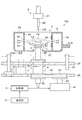
図5は、本発明の変形例に係わるスピンコートする態様を示すスピンコート装置100の側面模式図である。
(Modification 1)
In the spin coater 1, the
FIG. 5 is a schematic side view of a
図5において、スピンコート装置100は、スピンカップ5に対して、回転機構4(回転保持台3および眼鏡レンズL)が昇降して、眼鏡レンズLのレンズ面上に吐出された余剰のハードコート液LQを、スピンカップ5の開口部56から回収し、領域β内に収容するものである。したがって、図1〜図4に基づいて説明したスピンコート装置1が、スピンカップ5を昇降するのに対して、回転機構4を昇降する点で異なる。このため、図1〜図4に示したスピンコート装置1と同一の構成については、同一の符号を付して説明を適宜省略する。また、眼鏡レンズLのレンズ面にハードコート液LQを塗布処理するスピンコート方法についても同様であり、これについても適宜省略する。
In FIG. 5, the
スピンコート装置100は、基台90と、眼鏡レンズLを保持する回転保持台3と、回転保持台3を回転する回転機構4と、回転保持台3を収容する円筒形のスピンカップ5と、回転機構4が取り付けられた昇降台20と、昇降台20(回転機構4および回転保持台3)を昇降する昇降ユニット7と、塗布液を吐出する吐出部8と、制御部9と、操作部10を備えている。
The
基台90は、例えば円形状を成し、基台90の上方に配設された円筒形のスピンカップ5の外周を取り囲む位置に、三本の案内軸91が軸止されている。この三本の案内軸91は、円形状を3等分する中心角上の中心から略等距離の位置に配設されている。また、基台90の中心部に回転機構4が取付られ、回転機構4と三本の案内軸91との間の基台90の上面に、昇降ユニット7が着設されている。
The
回転機構4は、スピンドルモータ41と、スピンドルモータ41の駆動軸42と、第1のプーリー43と、タイミングベルト44と、第2のプーリー45と、回転保持台3の下部に連結された回転軸46とを備えている。この回転機構4は、回転軸46が軸受け等を介して昇降台20に回転可能に取り付けられている。
スピンカップ5は、カップ内に回転機構4の回転軸46に連結された回転保持台3を収容し、スピンコートする際に発生する余剰分の塗布液を処理するための容器であり、円筒形の側板部51と、底板部52と、円筒形の側壁53,54と、上板部55と、液体検出センサ57,58を含み構成され、図示しない筐体に固定されている。
The
The
このように構成されたスピンコート装置100を用いた眼鏡レンズLのレンズ面上にハードコート液LQを塗布する塗布処理は、眼鏡レンズLが回転保持台3に吸着保持される。そして、制御部9の制御信号に基づいて昇降ユニット7の油圧ポンプ71が作動することによりロッド72が伸縮して、昇降台20および昇降台20に取り付けられた回転機構4が、基台90に設けられた三本の案内軸91に案内されて、回転軸46の軸方向に沿って昇降し、所定の位置に停止する。
なお、昇降台20および昇降台20に着設された回転機構4の昇降の際には、昇降台20に連動してハードコート液LQを吐出する吐出部8が昇降するのが望ましい。
In the coating process of applying the hard coat liquid LQ onto the lens surface of the spectacle lens L using the
When the
そして、スピンドルモータ41が回転駆動し、回転保持台3に取り付けられた眼鏡レンズLが回転するとともに、吐出部8の吐出ノズル82から眼鏡レンズLの凹面La上に、ハードコート液LQが吐出され、ハードコート液LQの塗布が行われる。凹面Laへのハードコート液LQのスピンコートの際、回転する眼鏡レンズLのレンズ面上に吐出された余剰のハードコート液LQは、遠心力で凹面La上からスピンカップ5の側壁53,54の方向に向かって放射状に、図5中に矢印aで示す方向に振り切られ、スピンカップ5の開口部56から回収され、領域β内に収容されると共に、凹面Laに所定膜厚の塗膜が略均一に形成される。
Then, the
凹面Laにハードコート液LQの塗膜が形成された眼鏡レンズLは、回転保持台3から取り外された後に、仮焼成(仮硬化処理)が行われる。そして、もう一方のレンズ面である凸面Lbに、ハードコート液LQの塗布処理が行われる。
凸面Lbへの塗布処理は、眼鏡レンズLが回転保持台3に吸着保持された後に、制御部9の制御信号に基づいて昇降ユニット7の油圧ポンプ71が作動することによりロッド72が伸縮して、昇降台20および昇降台20に取り付けられた回転機構4が、回転軸46の軸方向に沿って昇降し、所定の位置に停止する(図5中、二点鎖線で示す)。
The spectacle lens L on which the coating film of the hard coat liquid LQ is formed on the concave surface La is removed from the rotary holding table 3 and then subjected to temporary baking (temporary curing process). And the coating process of the hard-coat liquid LQ is performed to the convex surface Lb which is the other lens surface.
After the spectacle lens L is sucked and held on the rotation holding table 3, the
そして、凹面Laと同様に凸面Lbに所定膜厚の塗膜が略均一に形成される。この凸面Lbのハードコート液LQのスピンコートの際、回転する眼鏡レンズLのレンズ面上に吐出された余剰のハードコート液LQは、遠心力で凸面Lb上から放射状に、図5中に二点鎖線の矢印bで示す方向に振り切られ、スピンカップ5の開口部56から回収され、領域β内に収容される。
And the coating film of a predetermined film thickness is formed substantially uniformly on the convex surface Lb similarly to the concave surface La. In the spin coating of the hard coat liquid LQ on the convex surface Lb, the excessive hard coat liquid LQ discharged onto the lens surface of the rotating spectacle lens L is radiated from the convex surface Lb by centrifugal force in two directions in FIG. It is shaken off in the direction indicated by the dotted line arrow b, recovered from the
このようにスピンコート装置100を用いた眼鏡レンズLのレンズ面上にハードコート液LQを塗布する塗布処理は、前述の実施形態におけるスピンコート装置1と同様な効果が得られる。また、回転保持台とスピンカップを相対移動する昇降方式を適宜選択することにより、スピンコート装置の設計自由度が向上する。
In this way, the coating process of applying the hard coat liquid LQ onto the lens surface of the spectacle lens L using the
(変形例2)
回転する眼鏡レンズLのレンズ面(凹面Laおよび凸面Lb)上から振り切られた余剰のハードコート液LQが、スピンカップ5の開口部56から回収されずに、側壁53あるいは側壁54に衝突した場合に行われる昇降台6および昇降台6に着設されたスピンカップ5を昇降する位置補正は、ハードコート液LQの塗布処理前の純水洗浄の際に行われるのが好ましい。
これにより、使用するハードコート液LQの消費を抑えることができる。また、より好適な塗膜を形成することが可能となる。
(Modification 2)
When excessive hard coat liquid LQ shaken off from the lens surfaces (concave surface La and convex surface Lb) of the rotating spectacle lens L collides with the
Thereby, consumption of the hard coat liquid LQ to be used can be suppressed. In addition, a more suitable coating film can be formed.
(変形例3)
スピンコート装置1は、スピンカップ5の開口部56を挟む位置に一対の液体検出センサ57,58を配設した場合で説明したが、液体検出センサ57,58を用いない構成であっても良い。この場合には、眼鏡レンズLの各レンズ面へのハードコート液LQの塗布処理前に、回転保持台3に吸着保持された眼鏡レンズLのレンズ面に純水洗浄等を行う際に、レンズ面上に吐出された洗浄液(純水)が遠心力で振り切られる状態に基づいて、手動で眼鏡レンズLとスピンカップ5の開口部56を相対移動すれば良い。
(Modification 3)
Although the spin coater 1 has been described in the case where the pair of
(変形例4)
スピンコート装置1は、眼鏡レンズLのレンズ面に塗布液としてハードコート液LQを用いた場合で説明したが、レンズに表面処理を行うハードコート液LQ以外の表面塗布液、例えばプライマー液、反射防止膜用組成液、撥水液、染色液等の場合であっても良い。これらの塗布液であっても、ハードコート液LQと同様にスピンコートすることができる。
(Modification 4)
The spin coater 1 has been described in the case where the hard coat liquid LQ is used as the coating liquid on the lens surface of the spectacle lens L. However, a surface coating liquid other than the hard coat liquid LQ for performing a surface treatment on the lens, for example, a primer liquid, a reflection liquid It may be a case of a composition liquid for a protective film, a water repellent liquid, a dyeing liquid or the like. Even these coating liquids can be spin-coated in the same manner as the hard coating liquid LQ.
(変形例5)
スピンコート装置1は、眼鏡レンズL以外に、調光用レンズ、カメラレンズ、望遠鏡レンズ、プロジェクタレンズ、マイクロレンズ等の光学レンズに適用することができる。これらのレンズであっても眼鏡レンズLと同様にスピンコートすることができる。
(Modification 5)
In addition to the spectacle lens L, the spin coat apparatus 1 can be applied to optical lenses such as a light control lens, a camera lens, a telescope lens, a projector lens, and a microlens. Even these lenses can be spin-coated in the same manner as the eyeglass lens L.
1,100…スピンコート装置、2,90…基台、3…回転保持台、4…回転機構、5…スピンカップ、6,20…昇降台、7…昇降ユニット、8…吐出部、9…制御部、41…スピンドルモータ、46…回転軸、51…側板部、51A…排気管、52…底板部、52A…排液管、53、54…側壁、55…上板部、56…開口部、57,58…検出センサとしての液体検出センサ、71…油圧ポンプ、72…ロッド、81…吐出バルブ、82…吐出ノズル、L…レンズとしての眼鏡レンズ、La…レンズ面としての凹面、Lb…レンズ面としての凸面、LQ…塗布液としてのハードコート液、α…開口部56の幅、β…回転体形状の領域。
DESCRIPTION OF SYMBOLS 1,100 ... Spin coater, 2,90 ... Base, 3 ... Rotation holding base, 4 ... Rotation mechanism, 5 ... Spin cup, 6,20 ... Lifting table, 7 ... Lifting unit, 8 ... Discharge part, 9 ...
Claims (3)
上面に前記レンズを載置して垂直軸回りに回転する回転保持台と、
前記回転保持台の周囲を覆うスピンカップと、
前記レンズに塗布液を吐出する吐出部と、を備え、
前記スピンカップの側壁に、回転する前記レンズから振り切られた前記塗布液を回収する開口部が設けられていることを特徴とするレンズのスピンコート装置。 A spin coat apparatus for applying a coating to a lens by a spin coat method,
A rotation holding base that mounts the lens on the upper surface and rotates around a vertical axis;
A spin cup covering the periphery of the rotary holding table;
A discharge unit for discharging a coating liquid to the lens,
A spin coating apparatus for a lens, wherein an opening for collecting the coating solution shaken off from the rotating lens is provided on a side wall of the spin cup.
回転する前記レンズから振り切られた前記塗布液の前記スピンカップ側壁への到達位置が前記開口部位置となるよう、前記スピンカップと前記回転保持台とを、前記レンズのレンズ面形状および前記レンズを回転させる際の回転数に基づき、前記回転保持台の垂直軸方向に相対移動することを特徴とするレンズのスピンコート装置。 In the spin coating apparatus of the lens of Claim 1,
The spin cup and the rotation holding table are arranged so that the position where the coating liquid shaken off from the rotating lens reaches the spin cup side wall is the opening position, the lens surface shape of the lens and the lens A spin coating apparatus for a lens, wherein the rotation holding table is relatively moved in a vertical axis direction based on a rotation speed at the time of rotation.
前記スピンコート装置は、
前記回転保持台の垂直軸方向に沿って、前記開口部を挟んだ前記スピンカップ側壁の上下面にそれぞれ前記塗布液を検出する一対の検出センサを、さらに備え、
前記一対の検出センサが前記回転するレンズから振り切られた塗布液の付着を検出したとき、前記スピンカップと前記回転保持台とを前記回転保持台の垂直軸方向に相対移動する位置補正が行われることを特徴とするレンズのスピンコート装置。
In the spin coating apparatus of the lens of Claim 1 or 2,
The spin coater is
A pair of detection sensors for detecting the coating liquid on the upper and lower surfaces of the spin cup side wall across the opening along the vertical axis direction of the rotation holding table, respectively,
When the pair of detection sensors detect adhesion of the coating liquid shaken off from the rotating lens, position correction is performed such that the spin cup and the rotation holding table are relatively moved in the vertical axis direction of the rotation holding table. A spin coating apparatus for a lens.
Priority Applications (1)
| Application Number | Priority Date | Filing Date | Title |
|---|---|---|---|
| JP2006055878A JP2007229648A (en) | 2006-03-02 | 2006-03-02 | Spin coat apparatus for lens |
Applications Claiming Priority (1)
| Application Number | Priority Date | Filing Date | Title |
|---|---|---|---|
| JP2006055878A JP2007229648A (en) | 2006-03-02 | 2006-03-02 | Spin coat apparatus for lens |
Publications (2)
| Publication Number | Publication Date |
|---|---|
| JP2007229648A true JP2007229648A (en) | 2007-09-13 |
| JP2007229648A5 JP2007229648A5 (en) | 2008-12-18 |
Family
ID=38550772
Family Applications (1)
| Application Number | Title | Priority Date | Filing Date |
|---|---|---|---|
| JP2006055878A Withdrawn JP2007229648A (en) | 2006-03-02 | 2006-03-02 | Spin coat apparatus for lens |
Country Status (1)
| Country | Link |
|---|---|
| JP (1) | JP2007229648A (en) |
Cited By (5)
| Publication number | Priority date | Publication date | Assignee | Title |
|---|---|---|---|---|
| JP2013140302A (en) * | 2012-01-06 | 2013-07-18 | Hoya Corp | Spectacle lens coating liquid coating device |
| JP2013186349A (en) * | 2012-03-08 | 2013-09-19 | Hoya Lense Manufacturing Philippine Inc | Optical element manufacturing method |
| CN107399567A (en) * | 2016-05-19 | 2017-11-28 | 中西金属工业株式会社 | Trolley conveyor with elevating function |
| CN109675744A (en) * | 2017-09-29 | 2019-04-26 | 临海市劳尔机械有限公司 | A kind of glasses lens plated flush coater |
| CN111487867A (en) * | 2020-04-16 | 2020-08-04 | 浙江大学 | Liquid sloshing model reference self-adaptive inhibition motion control method |
Citations (2)
| Publication number | Priority date | Publication date | Assignee | Title |
|---|---|---|---|---|
| JP2001269609A (en) * | 2000-03-28 | 2001-10-02 | Tokyo Electron Ltd | Coating processing device |
| JP2002177852A (en) * | 2000-12-15 | 2002-06-25 | Topcon Corp | Lens coating apparatus for lens of spectacles |
-
2006
- 2006-03-02 JP JP2006055878A patent/JP2007229648A/en not_active Withdrawn
Patent Citations (2)
| Publication number | Priority date | Publication date | Assignee | Title |
|---|---|---|---|---|
| JP2001269609A (en) * | 2000-03-28 | 2001-10-02 | Tokyo Electron Ltd | Coating processing device |
| JP2002177852A (en) * | 2000-12-15 | 2002-06-25 | Topcon Corp | Lens coating apparatus for lens of spectacles |
Cited By (5)
| Publication number | Priority date | Publication date | Assignee | Title |
|---|---|---|---|---|
| JP2013140302A (en) * | 2012-01-06 | 2013-07-18 | Hoya Corp | Spectacle lens coating liquid coating device |
| JP2013186349A (en) * | 2012-03-08 | 2013-09-19 | Hoya Lense Manufacturing Philippine Inc | Optical element manufacturing method |
| CN107399567A (en) * | 2016-05-19 | 2017-11-28 | 中西金属工业株式会社 | Trolley conveyor with elevating function |
| CN109675744A (en) * | 2017-09-29 | 2019-04-26 | 临海市劳尔机械有限公司 | A kind of glasses lens plated flush coater |
| CN111487867A (en) * | 2020-04-16 | 2020-08-04 | 浙江大学 | Liquid sloshing model reference self-adaptive inhibition motion control method |
Similar Documents
| Publication | Publication Date | Title |
|---|---|---|
| JP2007229648A (en) | Spin coat apparatus for lens | |
| KR101042762B1 (en) | Substrate processing apparatus and substrate processing method | |
| KR101163308B1 (en) | Film forming system and method using application nozzle | |
| US20070296063A1 (en) | Spin coating apparatus and coating method of composition for antireflection layer | |
| EP1577930A1 (en) | Coating device and coating film forming method | |
| US20210072645A1 (en) | Coater with automatic cleaning function and coater automatic cleaning method | |
| JP4774274B2 (en) | Coating equipment | |
| JP6971587B2 (en) | Optical elements and their manufacturing methods, optical equipment | |
| US8613982B2 (en) | Method of producing coated lenses | |
| JP6712482B2 (en) | Substrate processing method and substrate processing apparatus | |
| JP6655882B2 (en) | Manufacturing equipment for lenses with light-blocking layers | |
| JP6655881B2 (en) | Manufacturing method of lens with light-shielding layer | |
| JP6401184B2 (en) | Edgeable ophthalmic lens comprising a hydrophobic bilayer and a temporary metal fluoride layer | |
| KR101977771B1 (en) | Apparatus for treating substrate | |
| TWI708641B (en) | Substrate treatment method | |
| CN105390427A (en) | Transportation device and substrate processing device | |
| JP2008116348A (en) | Suitability determination method for organic antireflection film of plastic lens, and manufacturing method of the plastic lens | |
| JP2007102057A (en) | Method of manufacturing lens and device for manufacturing same | |
| JP2008168282A (en) | Layer forming method and layer formation apparatus | |
| KR102295573B1 (en) | Apparatus and Method for treating substrate | |
| JP4677573B2 (en) | Spin coating device, spin coating method | |
| KR200211244Y1 (en) | Semiconductor wafer coater | |
| JP5927037B2 (en) | Thin film manufacturing method | |
| KR101977757B1 (en) | Apparatus for treating substrate | |
| JP2000155424A (en) | Coating applicator and coating application method |
Legal Events
| Date | Code | Title | Description |
|---|---|---|---|
| A521 | Written amendment |
Free format text: JAPANESE INTERMEDIATE CODE: A523 Effective date: 20081029 |
|
| A621 | Written request for application examination |
Free format text: JAPANESE INTERMEDIATE CODE: A621 Effective date: 20081029 |
|
| A977 | Report on retrieval |
Free format text: JAPANESE INTERMEDIATE CODE: A971007 Effective date: 20101118 |
|
| A131 | Notification of reasons for refusal |
Free format text: JAPANESE INTERMEDIATE CODE: A131 Effective date: 20101124 |
|
| A761 | Written withdrawal of application |
Free format text: JAPANESE INTERMEDIATE CODE: A761 Effective date: 20110119 |