JP2007218043A - Joint securing structure of wooden building, fitting for joint securing structure, column base structure, fitting for column base structure, column-beam joint structure, and fitting for column-beam joint structure - Google Patents
Joint securing structure of wooden building, fitting for joint securing structure, column base structure, fitting for column base structure, column-beam joint structure, and fitting for column-beam joint structure Download PDFInfo
- Publication number
- JP2007218043A JP2007218043A JP2006042749A JP2006042749A JP2007218043A JP 2007218043 A JP2007218043 A JP 2007218043A JP 2006042749 A JP2006042749 A JP 2006042749A JP 2006042749 A JP2006042749 A JP 2006042749A JP 2007218043 A JP2007218043 A JP 2007218043A
- Authority
- JP
- Japan
- Prior art keywords
- column
- plate
- wooden
- core plate
- bolts
- Prior art date
- Legal status (The legal status is an assumption and is not a legal conclusion. Google has not performed a legal analysis and makes no representation as to the accuracy of the status listed.)
- Pending
Links
Images


Landscapes
- Joining Of Building Structures In Genera (AREA)
Abstract
Description
本発明は,木造建築物における接合緊締構造とその金具,柱脚構造とその金具,および柱・梁接合構造とその金具に関する。 The present invention relates to a joint tightening structure and its metal fitting in a wooden building, a column base structure and its metal fitting, and a column / beam joint structure and its metal fitting.
木造建築物において二つの木質材を繋ぎ合わせる接合部分としては,柱と土台との接合部分,柱と梁(桁)との接合部分等があるが,これらの接合部分をどのような接合緊締用金具を使用し,どのような接合緊締構造とするかについて,既に様々なものが提案されている。 The joints that connect two wooden materials in a wooden building include joints between pillars and foundations, joints between pillars and beams (girder), etc. Various things have already been proposed as to what kind of tightening structure to use with metal fittings.
柱と土台の接合部分を例にみると,上面に芯板を直立した鋼材製の柱支持台を布基礎上にアンカーボルトで固定し,柱を,その下端部に掘削形成してある嵌合溝を上記芯板に嵌合した状態で上記柱支持台上に設立させ,ドリフトピンまたはボルト・ナットにより,その柱の下端部と芯板とを結合固定した構成のもの(特許文献1〜3)等がある。
In the example of the joint between the pillar and foundation, a steel pillar support with an upright core plate on the upper surface is fixed to the fabric foundation with anchor bolts, and the pillar is drilled at its lower end. A structure in which a groove is established on the column support in a state of being fitted to the core plate, and the lower end portion of the column and the core plate are coupled and fixed by drift pins or bolts and nuts (
また,柱と梁の接合部分を例にみると,柱の側面に所要の形状にした接合金具主体を固定するとともに,その接合金具主体に梁の端部を嵌合し,かつこれら接合金具主体と梁との間に楔片を打ち込むことにより,梁の全体を柱側に移動させ,その柱の側面に圧接緊締状態にするもの(特許文献4)や,上記接合金具主体の中央窓孔内に植設したボルトに螺合してあるナットを,そのボルトの先端側に螺進することにより梁全体を柱側に移動させ,その柱の側面に圧接緊締状態にするもの(特許文献5)等がある。 For example, the joint between the column and the beam is fixed to the side of the column with the main part of the joint, and the end of the beam is fitted to the main part of the joint. By driving a wedge piece between the beam and the beam, the entire beam is moved to the column side, and the side surface of the column is pressed and tightened (Patent Document 4), or in the central window hole mainly of the above-mentioned joint fitting A nut that is screwed to a bolt installed in the screw is screwed to the tip side of the bolt to move the entire beam to the column side, and is brought into a pressure-contact tightened state on the side surface of the column (Patent Document 5) Etc.
しかしながら,上記柱と土台の接合部分の接合緊締構造(柱脚構造)は,全体として剛体構造をなし,柱を柱支持台上に強固に設立しているとはいえ,地震等による揺振力が上記芯板の長さ方向に作用したときに比べ,厚さ方向に作用したときは脆弱であり,また,地震等による揺振力は,当然ながら,上記芯板の長さ方向や厚さ方向に常に直角に作用するとは限らず,これら両方向とは異なるあらゆる方向から作用する可能性があるが,そのようなときにはねじれ現象が起きることになる。 However, the joint tightening structure (column base structure) of the joint between the column and the base has a rigid structure as a whole, and although the column is firmly established on the column support base, the vibration force due to earthquakes, etc. Compared to when acting in the length direction of the core plate, it is weaker when acting in the thickness direction. It does not always act at right angles to the direction, and may act from any direction different from these two directions, but in such a case, a twisting phenomenon will occur.
しかも,上記の揺振力が作用した場合,柱支持台と布基礎とは,その固定関係を損なうことは少ないとしても,柱は上記芯板および柱支持台との間にねじれ現象を起こし,その大きさや反復回数等により,ひび割れしたり座屈したりするおそれがある。 In addition, when the above vibration force is applied, the column supports and the fabric foundation are less likely to damage the fixing relationship, but the column causes a twisting phenomenon between the core plate and the column support table, There is a risk of cracking or buckling depending on the size and number of repetitions.
また,上記柱と梁の接合緊締構造において,楔片を打ち込んで緊締するタイプの接合構造では,柱と梁の必要にして十分な緊締強度は,楔片の適度な打ち込み度合(あるいは深さ)によってもたらされ,それが不足であっても過剰であってもならないものであるが,それは専ら熟練者の勘に頼りながら定性的に把握されているにすぎないのに対し,上記ナットをボルトの先端側に螺進して緊締するタイプの接合緊締構造は,その構造の緊締強度を定量的に把握でき,構築管理等を合理的に行えるという利点がある。 In addition, in the above-mentioned column / beam joint tightening structure, in the type of joint structure in which a wedge piece is driven and tightened, the necessary and sufficient tightening strength of the column and beam has an appropriate driving degree (or depth) of the wedge piece. The nut is bolted, whereas it must be either qualitatively grasped solely by relying on the intuition of an expert. The joint tightening structure of the type that is screwed and tightened to the tip side has the advantage that the tightening strength of the structure can be quantitatively grasped and the construction management and the like can be rationalized.
しかし、上記のようにナットをボルトの先端側に螺進することによる緊締は,その最終緊締位置がボルトの先端に近いほど,ボルトの根元に作用させる剪断力を大にする。また,木材の乾燥や振動に起因してボルトによる緊締が緩んだ場合には,当該ナットをさらに螺進して緊締しなおさない限り,緩んだままで放置されることになり,特に地震対策上好ましくないものである。 However, the tightening by screwing the nut to the tip end side of the bolt as described above increases the shearing force that acts on the root of the bolt as the final tightening position is closer to the tip of the bolt. Also, if the bolt tightening is loosened due to drying or vibration of the wood, it will be left loose unless the nut is further screwed and tightened again, which is particularly desirable for earthquake countermeasures. There is nothing.
本発明の目的の一つは,このナットをボルトの先端側に螺進して緊締するタイプの接合緊締構造の改良に関し,上記欠点を解消することにある。 One of the objects of the present invention is to eliminate the above-mentioned drawbacks with respect to the improvement of the joint tightening structure in which the nut is screwed and tightened to the tip end side of the bolt.
一般に梁や柱は,それが丸太からの製材であるとき当初含水率約30%を経年低下させて縮径し,集成材であるとき当初含水率約7%を経年増加させて拡径するが,このような経年変化にともなう梁と柱の接合部の接合度合の変化,柱と柱支持台またはその上面の芯板との間の嵌合度または密着度の変化に,上記従来公知の構造のものでは全く対応しきれない。 In general, when beams and columns are made from logs, the initial moisture content is reduced by about 30% and the diameter is reduced, and when laminated, the initial moisture content is increased by about 7% and the diameter is expanded. The above-mentioned conventionally known structure is affected by the change in the degree of joint between the beam and the column due to such aging, and the change in the degree of fitting or adhesion between the column and the column support base or the core plate on the upper surface. Things cannot be handled at all.
本発明の他の目的は,第1に,従来に比べ梁と柱の接合度合,また,柱支持台と柱との結合固定を一層強固にすること,第2に,地震等による揺振力が何れの方向から作用した場合においても,梁や柱がひび割れや座屈を起こすのを阻止すること,第3に,柱が経年変化で縮径または拡径した場合には,梁や柱の結合固定関係を最も適切な状態に追従維持することができるようにすることにある。 The other objects of the present invention are as follows. First, the degree of joint between the beam and the column and the coupling and fixing between the column support base and the column are further strengthened compared to the conventional one. Prevents the beam or column from cracking or buckling in any direction, and third, when the column shrinks or expands due to secular change, An object of the present invention is to be able to follow and maintain the coupling and fixing relationship in the most appropriate state.
請求項1記載の本発明の構成は次のとおりである。
ア) 内部を補強用の仕切り板6により仕切った鋼材製で角形短筒体をなす柱支持台aに,その天板2の上面中央に上記仕切り板6と対応一致させて起立した柱用芯板1と,その柱用芯板1の一側端面に当接しかつ天板2の一側辺縁部に起立した起立板10とからなる柱受枠bを一体に設けている。
イ) 上記天板2の他側辺縁部において上記柱用芯板1の他側端面にボルトとナットにより脱着自在に取り付けられ,上記起立板10に柱用芯板1を挟んで平行に対向し,これらの起立板10および柱用芯板1とで平面工の字形をなす柱用押当板dを備えている。
ウ) 上記柱用芯板1は,内周面に雌螺条を刻設した複数の螺孔11・ ・ ・を所要の間隔で縦横に列設するとともに,端面に複数本の横ボルト12・ ・ ・を同じく所要の間隔で列設している。
エ) 上記螺孔11の雌螺条に螺合する雄螺条15を中央所要長さ部分に刻設形成した複数の貫通係止ボルトcを備えていることを特徴とする木造建築物における柱脚構造用金具である。
The configuration of the present invention described in
A) A column core that stands up in a center of the upper surface of the
B) At the other side edge of the
C) The above-mentioned
D) A pillar in a wooden building comprising a plurality of through-locking bolts c formed by engraving
請求項2記載の本発明の構成は次のとおりである。
ア) 木質柱Cが,その下端部の中央に,上記請求項1に係る柱脚構造用金具の柱受枠bの柱用芯板1を受入する縦設溝17を形成するとともに,外周の対向両側面にそれぞれ上記起立板10,柱用押当板dを受入する切欠段部18,19を形成し,かつ,これら切欠段部18と19の間の部分に,複数のボルト用長孔20・ ・ ・を上記縦設溝17と直交する状態にして縦横に配列している。
イ) 上記柱受枠bの柱用芯板1と起立板10を,それぞれ木質柱Cの縦設溝17と切欠段部18に挿入または嵌合して,木質柱Cの底面を柱支持台aの天板2上に乗載している。
ウ) 上記柱用押当板dを,そのボルト孔13・・・を上記横ボルト12・・・に嵌めて上記切欠段部19に嵌入するとともにナット締めしている。
エ) 木質柱Cの上記ボルト用長孔20・ ・ ・の各々に,その一側から貫通係止ボルトcを挿入し,その雄螺条15を螺孔11・ ・ ・の雌螺条に噛合させてなることを特徴とする木造建築物における柱脚構造である。
The configuration of the present invention described in
A) The wooden column C is formed with a
B) The
C) The column pressing plate d is fitted into the
D) Insert a through-locking bolt c from one side of each of the bolt
請求項3記載の本発明の構成は次のとおりである。
ア) 底板21の一側の端縁21′を残した内方部位に柱当接板22を設立してなるL形枠23の内方中央において上記底板21と柱当接板22との間に梁用芯板24を設立支持するとともに,上記L形枠23の外方中央において上記端縁21′と柱当接板22との間に柱用芯板25を設立支持してなる鋼材製の金具本体eと,梁用当接板f,柱用押当板gおよび複数の貫通係止ボルトhとからなる。
イ) 上記金具本体eの上記梁用芯板24は,内周面に雌螺条を刻設した複数の螺孔29・ ・ ・を所要の間隔で列設するとともに,該梁用芯板24の上端面に複数の縦設ボルト26・ ・ ・を植立している。
ウ) 上記金具本体eの上記柱用芯板25は,その外端面に複数の横設ボルト32・ ・ ・を所要の間隔で植設している。
エ) 上記梁用当接板fは,上記縦設ボルト26・ ・ ・の各々と嵌合する複数の透孔27・ ・ ・を所要の間隔で開設している。
オ) 上記柱用押当板gは,上記柱用芯板25の外端面に所要の間隔で植立した横設ボルト32・ ・ ・の各々に嵌合する複数の透孔33・ ・ ・を所要の間隔で植設している。
カ) 上記貫通係止ボルトhは,その中央所要長さ部分に,上記螺孔29の雌螺条に螺合する雄螺条30を刻設形成していることを特徴とする木造建築物における柱・梁接合構造用金具である。
The configuration of the present invention described in claim 3 is as follows.
A) Between the
A) The
C) The
D) The beam contact plate f is provided with a plurality of through
E) The above-mentioned column pressing plate g has a plurality of through
F) The through-locking bolt h is formed with a
請求項4記載の本発明の構成は次のとおりである。
ア) 木質柱Cが,木質梁Gを接合する部分C′の中央内部に,上記請求項3に係る柱・梁接合構造用金具の上記柱用芯板25を受入する縦設溝35を形成するとともに,上記部分C′の外周面に,上記縦設溝35の前後両端開口に連続する角形凹処36,37を形成し,上記角形凹処36の下辺部分に横溝36′を連続形成している。
イ) 木質梁Gが,上記木質柱Cに接合する端部38の中央内部に,上記柱・梁接合構造用金具の梁用芯板24を受入する縦設溝39を形成するとともに,上記端部38の上面と下面に縦設溝39の上下両開口に連続する角形凹処40,41を形成し,かつ,上記端部38には,上記縦設溝39を横断するようにして複数のボルト用長孔42・ ・ ・を,上記梁用芯板24の複数の螺孔29・ ・ ・と同じ配置で横設貫通させている。
ウ) 上記柱・梁接合構造用金具の金具本体eの柱用芯板25を木質柱Cの縦設溝35に受入させ,横設ボルト32・ ・ ・を角形凹処37に突出させ,かつ,柱当接板22を角形凹処36に嵌入するとともに,底板21の端縁21′を横溝36′に嵌入し,透孔33・ ・ ・から突出する横設ボルト32・ ・ ・にナット34・ ・ ・を螺合緊締することによって,上記柱・梁接合構造用金具を木質柱Cの所定位置に取り付けている。
エ) 上記柱・梁接合構造用金具の金具本体eの梁用芯板24に,木質梁Gの端部38の上記縦設溝39を嵌合させるとともに,該端部38の底面の角形凹処41を金具本体eの底板21に嵌合し,かつ,上記縦設溝39に連続する上記角形凹処40に嵌合した梁用当接板fの透孔27・ ・ ・から突出する上記縦設ボルト26・ ・ ・をナット締めしている。
オ) 木質梁Gの端部38 のボルト用長孔42・ ・ ・の各々に,その一側から挿入した貫通係止ボルトhの雄螺条30を上記梁用芯板24の上記螺孔29・ ・ ・の雌螺条に噛合させてなることを特徴とする柱・梁接合構造である。
The configuration of the present invention described in
A) The
A) A
C) The
D) The
E) The
請求項5記載の本発明の構成は,請求項1記載の柱脚構造用金具(A)と請求項3記載の柱・梁接合構造用金具(E)とからなることを特徴とする木造建築物における接合緊締用金具である。
The structure of the present invention as defined in
請求項6記載の本発明の構成は,請求項2記載の木造建築物における柱脚構造(D)と請求項4記載の木造建築物における柱・梁接合構造(F)とからなることを特徴とする木造建築物における接合緊締構造である。
The structure of the present invention described in
本発明によれば,従来に比べ梁と柱の接合度合,また,柱支持台と柱との結合固定を一層強固にし,また,地震等による揺振力が何れの方向から作用した場合においても,梁や柱がひび割れや座屈を起こすのを阻止すること,さらには,柱が経年変化で縮径または拡径した場合には,梁や柱の結合固定関係を最も適切な状態に追従維持することができる。 According to the present invention, the degree of joint between the beam and the column and the coupling and fixing between the column support and the column are further strengthened compared to the conventional case, and the vibration force caused by an earthquake or the like is applied from any direction. , To prevent the beams and columns from cracking and buckling, and to maintain the beam / column connection and fixing relationship in the most appropriate state when the columns are reduced or expanded due to aging. can do.
以下に図示の実施例について詳述する。 The illustrated embodiment will be described in detail below.
以下に本発明の実施例を図面を参照しながら詳述する。
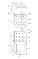
図1〜6は,木造建築物における柱と土台の接合部分である柱脚構造とその柱脚構造用金具を示している。
Embodiments of the present invention will be described in detail below with reference to the drawings.
FIGS. 1-6 has shown the column base structure and its column base structure metal fittings which are the junction parts of the pillar and foundation in a wooden building.
Aは柱脚構造用金具で,概括的には,布基礎B上に乗載固定する鋼材製の柱支持台aと,これと一体な同じく鋼材製の柱受枠bと,この柱受枠bの柱用芯板1と木質柱Cの下端部とを貫通係止する複数本の貫通係止ボルトcと,上記柱用芯板1の端面に取外し自在に取り付ける柱用押当板dとからなる。
A is a column base structural bracket. Generally, a steel column support base a that is mounted and fixed on the cloth foundation B, a steel column support frame b that is integrated with the steel column support base b, and the column support frame b. It comprises a plurality of penetration locking bolts c that penetrate and lock the
上記柱脚構造用金具Aにより木質柱Cを起立支持した構造が柱脚構造Dで,その詳細を,上記柱支持台a,柱受枠b等の構成とともに具体的に説明すると次のとおりである。 The structure in which the wooden column C is supported upright by the column base metal fitting A is the column base structure D. The details thereof will be described together with the configuration of the column support base a, the column receiving frame b and the like as follows. .
鋼材製の上記柱支持台aは,各々正方形状の天板2,底板3および外側板4,5で形成された角形短筒体内を補強用の仕切り板6により2分してなる。
この柱支持台aは,布基礎Bに植設したアンカーボルト7,7(一方のみ図示)を上記底板3のボルト孔8,8を通じ突出させ,その突出端部にナット9,9を螺合緊締することにより,布基礎B上に固定される(図6,14)。
The column support base a made of steel is formed by dividing a rectangular short cylinder formed by a square
This column support base a has
鋼材製の上記柱受枠bは,柱支持台aの天板2の上面中央に上記仕切り板6と対応一致させて起立した上記柱用芯板1と,この柱用芯板1の一側端面に当接するとともに天板2の一側辺縁部に起立した,起立板10とからなり,天板2の他側辺縁部において柱用芯板1の端面に柱用押当板dを脱着自在に取り付け,上記起立板10に柱用芯板1を挟んで平行に対向させることができる。
上記柱用芯板1,柱用押当板dおよび起立板10は,上記天板2等と同大の正方形状をなしている。
The column receiving frame b made of steel is composed of the
The
また,上記柱用芯板1は,内周面に雌螺条を刻設した複数の螺孔11・ ・ ・を所要の間隔で縦横に列設するとともに,端面に複数本の横ボルト12・ ・ ・を同じく所要の間隔で列設している。
The
上記貫通係止ボルトcは,上記各正方形状の一辺の長さと同じ長さを有するとともに,その中央所要長さ部分に,上記螺孔11の雌螺条に螺合する雄螺条15を刻設形成し,かつ,少なくとも一側端面にレンチ係合部16を有する。
The penetration locking bolt c has the same length as one side of each of the square shapes, and a
上記柱用押当板dは,中央縦線に沿って所要の間隔で透孔13・ ・ ・を設けていて,その各透孔13・ ・ ・を上記横ボルト12・ ・ ・に嵌合し,ナット14・ ・ ・により,柱用芯板1の端面に脱着自在に取り付けられ,それによって,該柱用押当板dは柱受枠bの柱用芯板1および起立板10とで平面工の字形をなす。
The column pressing plate d is provided with through
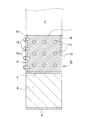
木質柱Cの下端部は,その中央に,柱受枠bの柱用芯板1を受入する縦設溝17を掘削形成するとともに,この縦設溝17と直交する対向両側面にそれぞれ上記起立板10,柱用押当板dを受入する切欠段部18,19を形成し,さらに,これら切欠段部18と19の間の部分には,複数のボルト用長孔20・ ・ ・を,上記縦設溝17と直交する状態にしてかつ所要の間隔で縦横に列設している。
At the lower end of the wooden column C, a
この木質柱Cの下端部と上記柱受枠bとは次のようにして嵌着する。
柱受枠bの柱用芯板1と起立板10を,木質柱Cの縦設溝17と切欠段部18に挿入または嵌合して,木質柱Cの下端部の底面を柱支持台aの天板2上に乗載する(図3)。
The lower end portion of the wooden column C and the column receiving frame b are fitted as follows.
The
そして,上記柱用押当板dを,そのボルト孔13・・・を横ボルト12・・・に嵌めつつ,上記切欠段部19に嵌入するとともに,その横ボルト12・・・にナット14・・・を緊締することにより,柱用押当板dを切欠段部19の内面に密接する状態において柱用芯板1の端面に取り付ける。
The column pressing plate d is inserted into the
さらに,木質柱Cのボルト用長孔20・ ・ ・の各々に,その一側から貫通係止ボルトcを回転させつつ挿入し,雄螺条15を螺孔11・ ・ ・の雌螺条に噛合させ,各貫通係止ボルトcの両側端面を木質柱Cの外周対向面に位置させる。
このようにして,木質柱Cの下端部と柱脚構造用金具Aとが,上下,前後および左右のいずれにも偏倚しない一体的関係をなして取り付けられ,かつ,木質柱Cは,その柱脚構造用金具Aを介して布基礎B上に強固に起立保持されることになる(図4〜6)。
Further, a through locking bolt c is inserted into each of the bolt holes 20 of the wooden pillar C while rotating from one side, and the
In this way, the lower end portion of the wooden column C and the column base structural bracket A are attached in an integral relationship that does not deviate vertically, front and back, and left and right, and the wooden column C is It is firmly held upright on the fabric foundation B via the leg structure bracket A (FIGS. 4 to 6).
上記構成の柱脚構造Dにおいて,木質柱Cに地震等による揺振力が加わった場合,木質柱Cの下端部と一体的関係をなしかつ柱支持台aとも一体をなす柱受枠bが,その柱用芯板1および起立板10と上記柱用押当板dが平面工の字形をなした状態において協働して対抗し,その木質柱Cがび割れや座屈を起こすのを阻止する。
In the column base structure D having the above configuration, when a vibration force due to an earthquake or the like is applied to the wooden column C, the column receiving frame b that is integrated with the lower end portion of the wooden column C and is also integrated with the column support base a, The
また,木質柱Cが,経年変化にともない柱受枠bの起立板10や柱用芯板1との間の嵌合度または密着度に変化を生じたときには,横ボルト12・・・に螺合しているナット14・・・の緊締度を調整することにより,常に最も適切な状態を維持することができる。
Further, when the wooden pillar C changes in the degree of fitting or close contact between the
なお,上記では,柱支持台aとして,角形短筒体の内部を仕切り板6で左右または前後に仕切るものについて説明したが,強度をより一層強固にするために,角形短筒体の内部を十字に仕切ることも当然可能である。
In the above description, the column support base a has been described in which the inside of the rectangular short cylinder is partitioned left and right or front and rear by the
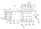
次に,図7〜13により,木造建築物における柱と梁(または桁,以下同じ。)の接合に使用する柱・梁接合構造用金具Eと,それを使用してなる柱・梁接合構造Fについて説明する。 Next, referring to FIGS. 7 to 13, a column / beam joint metal fitting E used for joining columns and beams (or girders, the same shall apply hereinafter) in a wooden building, and a column / beam joint structure using the same. F will be described.
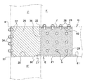
まず,柱・梁接合構造用金具Eは,概括的には,長四角形の底板21の長手方向一側の端縁21′を残した内方部位に柱当接板22を設立してなるL形枠23の内方中央において上記底板21と柱当接板22との間に梁用芯板24を設立支持するとともに,上記L形枠23の外方中央において上記端縁21′と柱当接板22との間に柱用芯板25を設立支持してなる鋼材製の金具本体e,長四角形の梁用当接板f,柱用押当板gおよび複数の貫通係止ボルトh等から構成される。
First, the column / beam joint metal fitting E is generally formed by establishing a
上記金具本体eの梁用芯板24の上端面に縦設ボルト26・ ・ ・を所要の間隔で植立し,上記梁用当接板fは,その中央に上記縦設ボルト26・ ・ ・に嵌合する透孔27・ ・ ・を所要の間隔で開設している。なお,28は上記縦設ボルト26・ ・ ・に螺合するナットと座金ある。
また,上記梁用芯板24は,内周面に雌螺条を刻設した複数の螺孔29・ ・ ・を所要の間隔で縦横に列設し,上記複数の貫通係止ボルトhは,各々,その中央所要長さ部分に,上記螺孔29の雌螺条に螺合する雄螺条30を刻設形成し,かつ,少なくとも一側端面にレンチ係合部31を有する。
The
上記金具本体eの柱用芯板25は,その端面に複数の横設ボルト32・ ・ ・を所要の間隔で列設し,柱用押当板gは,上記横設ボルト32・ ・ ・に嵌合する複数の透孔33・ ・ ・を列設している。34・ ・ ・は各横設ボルト32・ ・ ・に螺合するナットである。
The
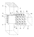
次に,前記木質柱Cは,木質梁Gを接合する部分C′の中央内部に,柱・梁接合構造用金具Eの上記柱用芯板25を受入する縦設溝35を掘削形成し,さらに上記部分C′の外周面に,縦設溝35の前後両端開口に連続する角形凹処36,37を対向する状態にして掘削形成している。36′は上記角形凹処36の下辺部分に連続形成した横溝である。
Next, the wood pillar C is formed by excavating and forming a
木質梁Gは,木質柱Cに接合する端部38の中央内部に,柱・梁接合構造用金具Eの上記梁用芯板24を受入する縦設溝39掘削形成している。
The wood beam G is formed by excavating a
また,木質梁Gは,端部38の上面と下面に,縦設溝39の上下両開口に連続する角形凹処40,41を対向する状態にして掘削形成し,その角形凹処40に上記梁用当接板fが一致嵌合し,角形凹処41には上記L形枠23の底板21が一致嵌合するようにしてある。
Further, the wooden beam G is formed by excavation on the upper and lower surfaces of the
さらに,上記端部38には,上記縦設溝39を横断するようにして複数のボルト用長孔42・ ・ ・を,上記梁用芯板24の複数の螺孔29・ ・ ・と同じ配置で横設貫通させている。
Further, a plurality of elongated bolt holes 42 are formed in the
本発明柱・梁接合構造Fは,木質柱Cに木質梁Gの端部38を接合緊締してなるもので,それにはまず,上記構成の柱・梁接合構造用金具Eを木質柱Cに対し次のように取り付ける。
すなわち,上記金具本体eの柱用芯板25を木質柱Cの縦設溝35に受入させることにより,横設ボルト32・ ・ ・を角形凹処37に突出させ,かつ,柱当接板22を角形凹処36に嵌入するとともに,底板21端縁21′を横溝36′に嵌入する(図9)。
The column / beam joint structure F of the present invention is formed by joining and tightening the
That is, by allowing the
そして,上記柱用押当板gを上記角形凹処35に嵌入し,横設ボルト32・ ・ ・を透孔33・ ・ ・から突出させ,その横設ボルト32・ ・ ・の各々にナット34・ ・ ・を螺合し緊締する。
これにより,柱・梁接合構造用金具Eが木質柱Cの所定位置にしっかりと取り付け固定される(図10)。
Then, the column pressing plate g is inserted into the
As a result, the column / beam joint metal fitting E is firmly attached and fixed at a predetermined position of the wooden column C (FIG. 10).
木質梁Gは,上記柱・梁接合構造用金具Eの金具本体eに対し次のように取り付けられる。
すなわち,木質梁Gの端部38を金具本体eに向けその上方から降下させ,該端部38の縦設溝39を金具本体eの梁用芯板24に嵌合させるとともに,該端部38の底面の角形凹処41を金具本体eの底板21に嵌合し,かつ,梁用芯板24に植立した縦設ボルト26・ ・ ・を,縦設溝39に連続する上記角形凹処40を通じその上方に突出させる。
The wooden beam G is attached to the bracket body e of the column / beam joint structural bracket E as follows.
That is, the
これにより,木質梁Gの端部38のボルト用長孔42・ ・ ・が梁用芯板24のボルト孔29・ ・ ・に一致連通する(図9,10)。
As a result, the bolt
また,上記梁用当接板fを,上記角形凹処40に嵌入し,上記縦設ボルト26・ ・ ・を透孔27・ ・ ・から突出させ,その縦設ボルト26・ ・ ・の各々にナット28・ ・ ・を螺進し緊締する。
さらに,木質梁Gのボルト用長孔42・ ・ ・の各々に,その一側から貫通係止ボルトhを回転させつつ挿入し,その雄螺条30を梁用芯板24の上記螺孔29・ ・ ・の雌螺条に噛合させ,各貫通係止ボルトhの両側端面を木質柱Cの外周対向面に位置させる(図11)。
これによって,木質梁Gと木質柱Cが一体的関係においてしっかりと接合緊締され,所期の柱・梁接合構造Fが構成される(図12,13)。
Further, the beam contact plate f is inserted into the
Further, a through-locking bolt h is inserted into each of the bolt
As a result, the wooden beam G and the wooden column C are firmly joined and tightened in an integrated relationship, and the desired column / beam connecting structure F is formed (FIGS. 12 and 13).
上記構成の本発明柱・梁接合構造Fおいては,第1に,柱・梁接合構造用金具Eの金具本体eが,その柱用芯板24を木質柱Cの縦設溝39に受入させ,柱当接板22を角形凹処36に嵌入し,かつ,底板21の端縁21′を横溝36′に嵌入するとともに,柱用押当板gを角形凹処37に嵌入し,それを横ボルト32・ ・ ・に螺合するナット34・ ・ ・で緊締することにより,該柱・梁接合構造用金具Eが木質柱Cの所定位置に取り付け固定される。
In the column / beam joint structure F of the present invention configured as described above, first, the bracket body e of the column / beam joint bracket E receives the
第2に,その柱・梁接合構造用金具Eに対し,木質梁Gが,その端部38の縦設溝39を金具本体eの梁用芯板24に嵌合させ,該端部38の底面の角形凹処41を金具本体eの底板21に嵌合し,さらに,角形凹処40に嵌入した梁用当接板fを,ナット28・ ・ ・により緊締し,かつ,木質梁Gのボルト用長孔42・ ・ ・の各々に挿入した貫通係止ボルトhの雄螺条30を梁用芯板24の螺孔29の雌螺条に緊密に噛合させることにより,すなわち,上記柱・梁接合構造用金具Eを介して,木質梁Gが木質柱Cの所要部位にしっかりと接合緊締される。
Secondly, the wooden beam G is fitted to the
また,木質柱Cや木質梁Gが,経年変化にともない上記金具本体eの柱用芯板25の嵌合度または密着度に変化を生じたときには,当該ナットによる緊締度を調整することにより,常に最も適切な状態を維持することができる。
Further, when the wooden pillar C or the wooden beam G changes in the fitting degree or the close contact degree of the
A 柱脚構造用金具
C 木質柱
C′ 部分
D 柱脚構造
E 柱・梁接合構造用金具
F 柱・梁接合構造
G 木質梁
a 柱支持台
b 柱受枠
c 貫通係止ボルト
d 柱用押当板
e 金具本体
f 梁用当接板
g 柱用押当板
h 貫通係止ボル
1 柱用芯板
2 天板
6 仕切り板
10 起立板
11 螺孔
12 横ボルト
13 ボルト孔
15 雄螺条
17 縦設溝
18 切欠段部
19 切欠段部
20 ボルト用長孔
21 底板
21′ 端縁
22 柱当接板
23 L形枠
24 梁用芯板
25 柱用芯板
27 透孔
29 螺孔
30 雄螺条
32 横設ボルト
33 透孔
34 ナット
35 縦設溝
36 角形凹処
36′ 横溝
37 角形凹処
38 端部
39 縦設溝
40 角形凹処
41 角形凹処
42 ボルト用長孔
A Column base structure bracket C Wood column C 'Part D Column base structure E Column / beam joint structure F Column / beam joint structure G Wood beam a Column support base Column support frame c Through lock bolt d Column pushing Plate e Metal fitting body f Beam contact plate g Column pressing plate h Through-locking
Claims (6)
イ. 上記天板(2)の他側辺縁部において上記柱用芯板(1)の他側端面にボルトとナットにより脱着自在に取り付けられ,上記起立板(10)に柱用芯板(1)を挟んで平行に対向し,これら起立板(10)および柱用芯板(1)とで平面工の字形をなす柱用押当板(d)を備え,
ウ. 上記柱用芯板(1)は,内周面に雌螺条を刻設した複数の螺孔(11・ ・ ・)を所要の間隔で縦横に列設するとともに,端面に複数本の横ボルト(12・ ・ ・)を同じく所要の間隔で列設し,
エ. かつ,上記螺孔(11)の雌螺条に螺合する雄螺条(15)を中央所要長さ部分に刻設形成した複数の貫通係止ボルト(c)を備えていることを特徴とする木造建築物における柱脚構造用金具。 A. A column support base (a) made of steel and having a rectangular short cylinder partitioned by a reinforcing partition plate (6) is made to correspond to the partition plate (6) at the center of the top surface of the top plate (2). A column core plate (1) that stands upright, and an upright plate (10) that abuts on one end face of the column core plate (1) and stands on one side edge of the top plate (2). A pillar support frame (b) is provided integrally,
I. At the other side edge of the top plate (2), it is detachably attached to the other side end surface of the column core plate (1) with bolts and nuts, and the column core plate (1) is attached to the upright plate (10). And a column pressing plate (d), which is parallel to each other with the upright plate (10) and the column core plate (1) in the shape of a plane.
C. The pillar core plate (1) has a plurality of screw holes (11,...) With internal threads engraved on the inner peripheral surface thereof arranged vertically and horizontally at a required interval, and a plurality of horizontal bolts on the end surface. (12 ...) are also arranged at the required intervals,
D. And a plurality of through-locking bolts (c) in which a male thread (15) to be screwed into the female thread of the screw hole (11) is formed in the central required length portion. Column base metal fittings for wooden buildings
イ. 上記柱受枠(b)の柱用芯板(1)と起立板(10)を,それぞれ木質柱(C)の縦設溝(17)と切欠段部(18)に挿入または嵌合して,木質柱(C)の底面を柱支持台(a)の天板(2)上に乗載し,
ウ. 上記柱用押当板(d)を,そのボルト孔(13・ ・ ・)を上記横ボルト(12・ ・ ・)に嵌めて上記切欠段部(19)に嵌入するとともにナット締めし,
エ. 木質柱(C)の上記ボルト用長孔(20・ ・ ・)の各々に,その一側から貫通係止ボルト(c)を挿入し,その雄螺条(15)を螺孔(11・ ・ ・)の雌螺条に噛合させてなることを特徴とする木造建築物における柱脚構造。 A. In the center of the lower end of the wooden column (C), a vertical groove (17) for receiving the column core plate (1) of the column receiving frame (b) of the column base structure bracket is formed, and Notch step portions (18, 19) for receiving the upright plate (10) and the column pressing plate (d) are formed on the opposite side surfaces, and between the notch step portions (18) and (19). A plurality of bolt holes (20,...) Are arranged vertically and horizontally in a state perpendicular to the longitudinal grooves (17),
I. The column core plate (1) and the upright plate (10) of the column receiving frame (b) are inserted or fitted into the longitudinal groove (17) and the notch step (18) of the wooden column (C), respectively. Place the bottom of the wooden pillar (C) on the top plate (2) of the pillar support (a),
C. The column pressing plate (d) is inserted into the notch step (19) with its bolt holes (13,...) Fitted into the horizontal bolts (12,...) And tightened with nuts.
D. A through-locking bolt (c) is inserted into each of the bolt holes (20,...) Of the wooden pillar (C) from one side, and the male thread (15) is inserted into the screw holes (11,. A column base structure in a wooden building characterized by being engaged with a female thread of ()).
イ. 上記金具本体(e)の上記梁用芯板(24)は,内周面に雌螺条を刻設した複数の螺孔(29・ ・ ・)を所要の間隔で列設するとともに,該梁用芯板(24)の上端面に複数の縦設ボルト(26・ ・ ・)を植立し,
ウ. 上記金具本体(e)の上記柱用芯板(25)は,その外端面に複数の横設ボルト(32・ ・ ・)を所要の間隔で植設し,
エ. 上記梁用当接板(f)は,上記縦設ボルト(26・ ・ ・)の各々と嵌合する複数の透孔(27・ ・ ・)を所要の間隔で開設し,
オ. 上記柱用押当板(g)は,上記柱用芯板(25)の外端面に所要の間隔で植立した横設ボルト(32・ ・ ・)の各々に嵌合する複数の透孔(33・ ・ ・)を所要の間隔で植設し,
カ. 上記貫通係止ボルト(h)は,その中央所要長さ部分に,上記螺孔(29)の雌螺条に螺合する雄螺条(30)を刻設形成していることを特徴とする木造建築物における柱・梁接合構造用金具。 A. The bottom plate (21) and the bottom plate (21) are formed at the inner center of an L-shaped frame (23) in which a column abutting plate (22) is established at an inner portion of the bottom plate (21) where an edge (21 ') on one side remains. The beam core plate (24) is established and supported between the column contact plate (22) and the edge (21 ') and the column contact plate (22) at the outer center of the L-shaped frame (23). A steel metal fitting body (e), a beam contact plate (f), a column pressing plate (g), and a plurality of through locking bolts. (H)
I. The beam core plate (24) of the metal fitting body (e) has a plurality of screw holes (29,...) Formed by engraving female threads on an inner peripheral surface thereof arranged at a predetermined interval, and the beam core plate ( 24) Plant a plurality of vertical bolts (26) on the upper end surface of
C. The pillar core plate (25) of the metal fitting body (e) has a plurality of lateral bolts (32,.
D. The beam contact plate (f) is provided with a plurality of through holes (27,...) Fitted with the vertical bolts (26,.
E. The column pressing plate (g) has a plurality of through-holes (32,...) Fitted to each of the lateral bolts (32,. 33 ・ ・ ・) are planted at the required intervals,
F. The penetration locking bolt (h) has a male thread (30) engraved and formed in the central required length portion thereof, which is screwed into the female thread of the screw hole (29). Metal fittings for connecting columns and beams in wooden buildings.
イ. 木質梁(G)が,上記木質柱(C)に接合する端部(38)の中央内部に,上記柱・梁接合構造用金具の梁用芯板(24)を受入する縦設溝(39)を形成するとともに,上記端部(38)の上面と下面に縦設溝(39)の上下両開口に連続する角形凹処(40,41)を形成し,かつ,上記端部(38)には,上記縦設溝(39)を横断するようにして複数のボルト用長孔(42・ ・ ・)を,上記梁用芯板(24)の複数の螺孔(29・ ・ ・)と同じ配置で横設貫通させ,
ウ. 上記柱・梁接合構造用金具の金具本体(e)の柱用芯板(25)を木質柱(C)の縦設溝(35)に受入させ,横設ボルト(32・ ・ ・)を角形凹処(37)に突出させ,かつ,柱当接板(22)を角形凹処(36)に嵌入するとともに,底板(21)の端縁(21′)を横溝(36′)に嵌入し,透孔(33・ ・ ・)から突出する横設ボルト(32・ ・ ・)にナット(34・ ・ ・)を螺合緊締することによって,上記柱・梁接合構造用金具を木質柱(C)の所定位置に取り付け,
エ. 上記柱・梁接合構造用金具の金具本体(e)の梁用芯板(24)に,木質梁(G)の端部(38)の上記縦設溝(39)を嵌合させるとともに,該端部(38)の底面の角形凹処(41)を金具本体(e)の底板(21)に嵌合し,かつ,上記縦設溝(39)に連続する上記角形凹処(40)に嵌合した梁用当接板(f)の透孔(27・ ・ ・)から突出する上記縦設ボルト(26・ ・ ・)をナット締めし,
オ. かつ,木質梁(G)の端部(38)のボルト用長孔(42・ ・ ・)の各々に,その一側から挿入した貫通係止ボルト(h)の雄螺条(30)を上記梁用芯板(24)の上記螺孔(29・ ・ ・)の雌螺条に噛合させてなることを特徴とする柱・梁接合構造。 A. A vertical groove (35) in which the wooden column (C) receives the column core plate (25) of the column / beam connecting bracket in the center (C ') where the wooden beam (G) is bonded. ) And rectangular recesses (36, 37) that are continuous with the front and rear openings of the vertical groove (35) are formed on the outer peripheral surface of the portion (C ′). A lateral groove (36 ') is continuously formed in the lower side portion of
I. A longitudinal groove (39) for receiving the beam core plate (24) of the pillar / beam joint metal fitting is provided in the center inside of the end (38) where the wood beam (G) joins the wood pillar (C). In addition, a rectangular recess (40, 41) is formed on the upper surface and the lower surface of the end portion (38) so as to be continuous with the upper and lower openings of the longitudinal groove (39), and the end portion (38) The plurality of bolt elongated holes (42,...) Are transversely arranged in the same arrangement as the plurality of screw holes (29,...) Of the beam core plate (24) so as to cross the vertical groove (39). Pierce through,
C. The column core plate (25) of the bracket body (e) of the above-mentioned bracket for the beam / beam connection structure is received in the vertical groove (35) of the wooden column (C), and the horizontal bolt (32,...) Is square. The column abutment plate (22) is inserted into the rectangular recess (36) and the edge (21 ') of the bottom plate (21) is inserted into the lateral groove (36'). , The nuts (34,...) Are screwed and tightened to the lateral bolts (32...) Protruding from the through holes (33. ) In place,
D. The vertical groove (39) of the end portion (38) of the wooden beam (G) is fitted to the beam core plate (24) of the metal fitting body (e) of the column / beam joining structure metal fitting, and the end portion The square recess (41) on the bottom surface of (38) is fitted to the bottom plate (21) of the metal fitting body (e) and is fitted to the square recess (40) continuous with the vertical groove (39). Tighten the above-mentioned vertical bolts (26,...) Protruding from the through holes (27,...) Of the beam contact plate (f),
E. And the male thread (30) of the penetration locking bolt (h) inserted from one side into each of the bolt long holes (42,...) At the end (38) of the wooden beam (G) is described above. A column / beam joint structure characterized by being engaged with a female thread of the screw hole (29,...) Of the beam core plate (24).
Priority Applications (1)
| Application Number | Priority Date | Filing Date | Title |
|---|---|---|---|
| JP2006042749A JP2007218043A (en) | 2006-02-20 | 2006-02-20 | Joint securing structure of wooden building, fitting for joint securing structure, column base structure, fitting for column base structure, column-beam joint structure, and fitting for column-beam joint structure |
Applications Claiming Priority (1)
| Application Number | Priority Date | Filing Date | Title |
|---|---|---|---|
| JP2006042749A JP2007218043A (en) | 2006-02-20 | 2006-02-20 | Joint securing structure of wooden building, fitting for joint securing structure, column base structure, fitting for column base structure, column-beam joint structure, and fitting for column-beam joint structure |
Publications (1)
| Publication Number | Publication Date |
|---|---|
| JP2007218043A true JP2007218043A (en) | 2007-08-30 |
Family
ID=38495616
Family Applications (1)
| Application Number | Title | Priority Date | Filing Date |
|---|---|---|---|
| JP2006042749A Pending JP2007218043A (en) | 2006-02-20 | 2006-02-20 | Joint securing structure of wooden building, fitting for joint securing structure, column base structure, fitting for column base structure, column-beam joint structure, and fitting for column-beam joint structure |
Country Status (1)
| Country | Link |
|---|---|
| JP (1) | JP2007218043A (en) |
Cited By (5)
| Publication number | Priority date | Publication date | Assignee | Title |
|---|---|---|---|---|
| JP4847616B1 (en) * | 2011-03-09 | 2011-12-28 | 幹夫 田代 | Rigid joint hardware with wooden structure |
| CZ304707B6 (en) * | 2013-03-21 | 2014-09-03 | Vysoká škola technická a ekonomická v Českých Budějovicích | Linear girder connection |
| JP2018115491A (en) * | 2017-01-19 | 2018-07-26 | ミサワホーム株式会社 | Building structure |
| JP2020002669A (en) * | 2018-06-29 | 2020-01-09 | 大和ハウス工業株式会社 | Joint structure of woody shaft member |
| CN112502282A (en) * | 2020-12-25 | 2021-03-16 | 桂林电子科技大学 | Take assembled bamboo wood combination post of metal connecting piece |
-
2006
- 2006-02-20 JP JP2006042749A patent/JP2007218043A/en active Pending
Cited By (8)
| Publication number | Priority date | Publication date | Assignee | Title |
|---|---|---|---|---|
| JP4847616B1 (en) * | 2011-03-09 | 2011-12-28 | 幹夫 田代 | Rigid joint hardware with wooden structure |
| JP2012188816A (en) * | 2011-03-09 | 2012-10-04 | Mikio Tashiro | Metal fixture for rigid joint of wooden structure |
| CZ304707B6 (en) * | 2013-03-21 | 2014-09-03 | Vysoká škola technická a ekonomická v Českých Budějovicích | Linear girder connection |
| JP2018115491A (en) * | 2017-01-19 | 2018-07-26 | ミサワホーム株式会社 | Building structure |
| JP2020002669A (en) * | 2018-06-29 | 2020-01-09 | 大和ハウス工業株式会社 | Joint structure of woody shaft member |
| JP7187188B2 (en) | 2018-06-29 | 2022-12-12 | 大和ハウス工業株式会社 | Joint structure of wooden shaft members |
| CN112502282A (en) * | 2020-12-25 | 2021-03-16 | 桂林电子科技大学 | Take assembled bamboo wood combination post of metal connecting piece |
| CN112502282B (en) * | 2020-12-25 | 2024-04-05 | 桂林电子科技大学 | Assembled bamboo-wood combined column with metal connecting piece |
Similar Documents
| Publication | Publication Date | Title |
|---|---|---|
| US6532713B2 (en) | Joint structure for joining composite beam and column | |
| JP3041271B2 (en) | Wooden joining method | |
| JP2007218043A (en) | Joint securing structure of wooden building, fitting for joint securing structure, column base structure, fitting for column base structure, column-beam joint structure, and fitting for column-beam joint structure | |
| JP5567994B2 (en) | Connector | |
| JP2010059765A (en) | Structure for fastening sill and column | |
| JP3209111U (en) | Vertical frame material and steel house | |
| JP2007138506A (en) | Joining and firmly tightening structure in wooden building, metal fitting for joining and firmly tightening, and metal fitting for column and beam joining structure | |
| JP5385314B2 (en) | Connected structure | |
| JP5415464B2 (en) | Connected structure | |
| JP3409137B2 (en) | Bearing wall structure of wooden frame | |
| JP2007218041A (en) | Joint securing structure of wooden building, fitting for joint securing structure, column base structure, fitting for column base structure, column-beam joint structure, and fitting for column-beam joint structure | |
| JP2006177108A (en) | Member fixture | |
| JP2017141542A (en) | Frame structure and method for assembling the same | |
| JP2004244941A (en) | Connector, joint structure of structural members using the connector, and structural member connecting method using the same | |
| JP2659154B2 (en) | Connection method and connection bracket between column and beam | |
| JP2008007997A (en) | Connection structure and connection metal fitting of wooden building | |
| JP4080419B2 (en) | Mounting structure of the joint fitting at the beam-column joint | |
| JP2008163651A (en) | Joining and firm-fastening structure of wooden building, and fitting therefor | |
| JP2007218042A (en) | Joint securing structure of wooden building, fitting for joint securing structure, column base structure, fitting for column base structure, column-beam joint structure, and fitting for column-beam joint structure | |
| JP2725174B2 (en) | Column and column joint structure of wooden building and its tools | |
| JP2004270446A (en) | Connection structure of structural members | |
| JP2017101414A (en) | Fitting structure of tension rod | |
| JP2016199942A (en) | Joint metal fitting for construction | |
| JP2021165525A (en) | Construction method of wooden rigid frame structure | |
| JP2021161631A (en) | Joint structure for woody shaft member |
Legal Events
| Date | Code | Title | Description |
|---|---|---|---|
| RD04 | Notification of resignation of power of attorney |
Free format text: JAPANESE INTERMEDIATE CODE: A7424 Effective date: 20080205 |
|
| RD02 | Notification of acceptance of power of attorney |
Free format text: JAPANESE INTERMEDIATE CODE: A7422 Effective date: 20080311 |
|
| RD04 | Notification of resignation of power of attorney |
Free format text: JAPANESE INTERMEDIATE CODE: A7424 Effective date: 20080312 |
|
| A711 | Notification of change in applicant |
Free format text: JAPANESE INTERMEDIATE CODE: A711 Effective date: 20090127 |