JP2007205379A - Pulley - Google Patents
Pulley Download PDFInfo
- Publication number
- JP2007205379A JP2007205379A JP2006022156A JP2006022156A JP2007205379A JP 2007205379 A JP2007205379 A JP 2007205379A JP 2006022156 A JP2006022156 A JP 2006022156A JP 2006022156 A JP2006022156 A JP 2006022156A JP 2007205379 A JP2007205379 A JP 2007205379A
- Authority
- JP
- Japan
- Prior art keywords
- pulley
- hub
- spring
- torque
- peripheral surface
- Prior art date
- Legal status (The legal status is an assumption and is not a legal conclusion. Google has not performed a legal analysis and makes no representation as to the accuracy of the status listed.)
- Pending
Links
Images

Landscapes
- Pulleys (AREA)
Abstract
Description
本発明は、巻掛け伝動機構に使用され、駆動側の回転変動に起因するベルトの張力変動を吸収できるプーリに関する。 The present invention relates to a pulley that is used in a winding transmission mechanism and that can absorb a belt tension variation caused by a rotational variation on a driving side.
特許文献1に、エンジンのトルクをベルトを介して補機(エアーコンディショナ、パワーステアリング、オルタネータ、ウォータポンプ等)に入力する補機駆動用プーリが記載されている。 Patent Document 1 describes an auxiliary machine driving pulley that inputs engine torque to an auxiliary machine (air conditioner, power steering, alternator, water pump, etc.) via a belt.
この補機駆動用プーリは、補機の入力軸に固定されるハブと、ハブの外周に相対的に回動可能に設けられたプーリ本体と、プーリ本体とハブとの間のトルクの伝達を行うトルク伝達手段とで構成され、トルク伝達手段は弾性部材を備えている。 This accessory driving pulley has a hub fixed to the input shaft of the accessory, a pulley body rotatably provided on the outer periphery of the hub, and transmission of torque between the pulley body and the hub. Torque transmitting means for performing, and the torque transmitting means includes an elastic member.
このような補機駆動用プーリでは、ベルトを介してプーリ本体に伝達された回転変動を含むトルクが弾性部材を介してハブ及び回転軸に伝達されることになるので、その回転変動を弾性部材の弾性変形によって吸収して補機側の入力軸にトルクを伝えることができる。従って、プーリ本体に巻回するベルトにかかる張力の変動を低減することができるので、ベルトの寿命の向上を図ることができる。
上記のような補機駆動用プーリでは、トルク伝達手段は、ハブに形成されたハブ側突部と、プーリ本体に形成されたプーリ側突部と、ハブ側突部とプーリ側突部とで形成された空間部に収容される弾性部材とで構成されている。このような補機駆動用プーリに用いられる弾性部材は、ゴム材などで形成されている。 In the accessory driving pulley as described above, the torque transmission means includes a hub-side protrusion formed on the hub, a pulley-side protrusion formed on the pulley body, a hub-side protrusion, and a pulley-side protrusion. It is comprised with the elastic member accommodated in the formed space part. The elastic member used for such an accessory driving pulley is formed of a rubber material or the like.
しかしながら、上記のような補機駆動用プーリに用いられる弾性部材では、過大なトルクが入力されると弾性部材が潰れてしまい、弾性部材のばね定数が著しく上昇してしまう。このため、過大なトルクが入力されると弾性部材の変動吸収機能が働かなくなってしまう可能性がある。 However, in the elastic member used for the accessory driving pulley as described above, if an excessive torque is input, the elastic member is crushed and the spring constant of the elastic member is significantly increased. For this reason, if an excessive torque is input, the fluctuation absorbing function of the elastic member may not work.
そこで、この発明は、回転変動の吸収機能を向上させることができるプーリの提供を目的としている。 Therefore, an object of the present invention is to provide a pulley that can improve the function of absorbing rotational fluctuation.
請求項1の発明は、回転軸に固定されるハブと、該ハブの外周に回転可能に設けられる筒状のプーリ本体と、該プーリ本体と前記ハブとの間のトルクを伝達するトルク伝達手段とを備えたプーリであって、前記ハブは内周面に前記回転軸が固定される筒状の円筒部を備え、前記プーリ本体は筒状に形成され、該プーリ本体の内周面と前記円筒部の外周面とが離間して空間部が形成され、前記トルク伝達手段は、前記空間部に収容され、一端部が前記プーリ本体に固定され他端部が前記ハブに固定されたスプリングであることを特徴とする。 The invention according to claim 1 is a hub fixed to a rotating shaft, a cylindrical pulley body rotatably provided on the outer periphery of the hub, and torque transmission means for transmitting torque between the pulley body and the hub. The hub includes a cylindrical cylindrical portion having an inner peripheral surface to which the rotation shaft is fixed, and the pulley main body is formed in a cylindrical shape, and the pulley main body has an inner peripheral surface and the pulley main body. A space portion is formed apart from the outer peripheral surface of the cylindrical portion, and the torque transmitting means is a spring that is housed in the space portion, one end portion is fixed to the pulley body, and the other end portion is fixed to the hub. It is characterized by being.
請求項2の発明は、請求項1記載のプーリであって、前記スプリングは、該スプリングに過大なトルクが前記ハブ又は前記プーリ本体に入力されると、スプリングが縮径して前記円筒部の外周面と当接する、又はスプリングが拡径して前記プーリ本体の内周面と当接する当接制御部が形成されていることを特徴とする。 The invention according to claim 2 is the pulley according to claim 1, wherein when an excessive torque is input to the hub or the pulley body, the spring is reduced in diameter and the spring of the cylindrical portion is reduced. An abutting control unit that abuts on the outer peripheral surface or a diameter of a spring that abuts on the inner peripheral surface of the pulley main body is formed.
請求項1のプーリは、トルク伝達手段として、従来のゴム材などから形成された弾性部材ではなく、スプリングを用いているので、過大なトルクが入力されても、トルクに対するばね定数の変化が小さいため、変動吸収は安定している。従って、プーリ本体側又はハブ側の回転変動を吸収することができ、回転変動の吸収機能を向上させることができる。 Since the pulley according to claim 1 uses a spring as a torque transmission means instead of a conventional elastic member formed of a rubber material or the like, even if an excessive torque is input, a change in the spring constant with respect to the torque is small. Therefore, fluctuation absorption is stable. Therefore, it is possible to absorb rotation fluctuations on the pulley main body side or the hub side, and to improve the function of absorbing rotation fluctuations.
また、スプリングは、一端部がプーリ本体に固定され、他端部がハブに固定されてプーリ本体とハブ間のトルクを伝達しているので、プーリ本体及びハブにトルクを伝達するための突部等の伝達部分を設ける必要がなく、プーリの構成を簡略化することができると共に、プーリ本体側及びハブ側の両方向の回転変動を吸収することができる。 The spring has one end fixed to the pulley main body and the other end fixed to the hub to transmit torque between the pulley main body and the hub, so that the protrusion for transmitting torque to the pulley main body and the hub. It is not necessary to provide a transmission part such as a pulley, the configuration of the pulley can be simplified, and rotational fluctuations in both directions on the pulley main body side and the hub side can be absorbed.
請求項2のプーリは、スプリングにはスプリングに過大なトルクが入力されると縮径又は拡径して、ハブの円筒部の外周面又はプーリ本体の内周面と当接する当接制御部が形成されているので、スプリングに過大なトルクが入力されると当接制御部がストッパ機能として働き、スプリングがそれ以上変形することができなくなる。このため、スプリングに過大なトルクが入力されても、スプリングはそれ以上変形せず、スプリングの損傷を抑えることができる。 The pulley according to claim 2 has a contact control portion that contracts or expands when an excessive torque is input to the spring and contacts the outer peripheral surface of the cylindrical portion of the hub or the inner peripheral surface of the pulley body. Thus, when an excessive torque is input to the spring, the contact control unit functions as a stopper function, and the spring cannot be further deformed. For this reason, even if an excessive torque is input to the spring, the spring is not further deformed, and damage to the spring can be suppressed.
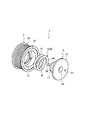
図1〜図3を用いて実施形態について説明する。 The embodiment will be described with reference to FIGS.
本実施形態のプーリ1は、回転軸3に固定されるハブ5と、ハブ5の外周に回転可能に設けられる筒状のプーリ本体7と、プーリ本体7とハブ5との間のトルクを伝達するトルク伝達手段9とを備えている。さらに、ハブ5は内周面に回転軸3が固定される筒状の円筒部11を備え、プーリ本体7は筒状に形成され、プーリ本体7の内周面と円筒部11の外周面とが離間して空間部13が形成され、トルク伝達手段9は、空間部13に収容され、一端部がプーリ本体7に固定され他端部がハブ5に固定されたスプリング15となっている。なお、スプリング15は、いわゆるコイルスプリングが設けられている。
The pulley 1 according to this embodiment transmits a torque between the
図1、図2に示すように、ハブ5は、内周面に回転軸3の先端部が螺合によって固定される円筒状の円筒部11と、円筒部11の一側の端部に一体的に形成された円板部17とを備えている。円板部17の中心部には、回転軸3を螺合する際に使用する治具が挿入される6角孔19が形成されている。また、円板部17には、後述するトルク伝達手段9であるスプリング15の固定部39を固定する固定孔21が形成されている。さらに、円筒部11の他側の外周面と回転軸3に圧入されるカラー23の外周面に、軸受25のインナレース27が圧入されている。
As shown in FIG. 1 and FIG. 2, the
プーリ本体7は、筒状に形成され、外周面にベルト(不図示)が巻掛けられるリム部29と、内周面にスペーサ31が圧入されて固定される固定凹部33とを備えている。プーリ本体7は、ハブ5の円筒部11の外周に離間して配置されている。そして、ハブ5の円筒部11の外周面とプーリ本体7の内周面によって空間部13が形成されている。また、プーリ本体7の一側の内周面には、軸受25のアウタレース35が圧入され、このアウタレース35と固定凹部33によってスペーサ31を固定している。さらに、スペーサ31には、スプリング15の固定部39を固定する固定孔37が形成され、空間部13には、トルク伝達手段9であるスプリング15が収容されている。
The
スプリング15は、両端部にスプリング引掛け部としてのハブ5の固定孔21とスペーサ31の固定孔37に固定される固定部39、39が形成されている。この固定部39、39とハブ5及びスペーサ31の固定孔21、37によって、ハブ5とプーリ本体7間のトルクの伝達がなされている。なお、スプリング引掛け部の形状は、孔に限定されず、スプリング15の両端部が固定できるのであれば、どの様な形状でも良い。また、スプリング15は、ハブ5とプーリ本体7間に回転差が生じると、縮径又は拡径するように設定されており、スプリング15のコイル部の内径側と外径側が、当接制御部41、41として形成されている。この当接制御部41、41は、ハブ5とプーリ本体7間にスプリング15による回転変動吸収機能が働かなくなる程の過大なトルクが入力され、スプリング15が縮径した場合、ハブ5の円筒部11の外周面と当接し、スプリング15が拡径した場合、プーリ本体7の内周面と当接する。これにより、スプリング15による回転変動吸収機能が働かなくなる程の過大なトルクが入力されると当接制御部41、41がストッパ機能として働き、スプリング15がそれ以上変形することができなくなる。なお、スプリング15の特性は、スプリング15の巻数、線の太さなどによって調整することができる。また、スプリング15にグリスの塗布及びテフロン(登録商標)等によるコーティングを施すことでスプリング同士の接触による異音、摩擦を防止することができる。
The
このように構成されたプーリ1は、駆動側プーリ(不図示)の回転によってベルト(不図示)に移動力が作用すると、ベルト(不図示)との摩擦力によってプーリ1のプーリ本体7にトルクが伝達される。そして、プーリ本体7からスプリング15を介してハブ5にトルクを伝達する。このハブ5の回転によって補機(不図示)側の回転軸3が回転される。
In the pulley 1 configured in this manner, when a moving force acts on a belt (not shown) due to rotation of a driving pulley (not shown), a torque is applied to the
この回転伝達過程にあって、駆動側の回転に回転変動が発生すると、この回転変動にベルト(不図示)が追従するように移動速度を変動させる。一方、ハブ5及び回転軸3は慣性によって一定回転数で回転しようとするので、ベルト(不図示)には張力の変動が生じることになる。しかし、プーリ本体7の回転に回転変動があるとスプリング15が弾性変形してその回転変動を吸収しつつハブ5に回転を伝達する。
In the rotation transmission process, when a rotation fluctuation occurs in the rotation on the driving side, the moving speed is changed so that a belt (not shown) follows the rotation fluctuation. On the other hand, since the
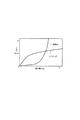
ここで、図3に、従来のゴム材などからなる弾性体と、スプリング15の捩れ角とトルクの関係を示す。弾性体では、過大なトルクが入力されたときや捩れ角が大きくなると、ばね定数が急に大きくなるため、捩れ角に対するトルクの傾斜がきつくなっており、回転変動の吸収機能が働く範囲が狭くなっている。これに対して、スプリング15では、過大なトルクが入力されたときや捩れ角が大きくなっても、ばね定数が安定し、捩れ角に対するトルクの傾斜は緩やかになっており、回転変動の吸収機能が働く範囲が、従来の弾性体に対して、非常に広くなっている。このため、スプリング15では、従来の弾性体では吸収できなかった範囲の回転変動を吸収することができる。
Here, FIG. 3 shows a relationship between a conventional elastic body made of a rubber material and the like, a twist angle of the
このようなプーリ1では、トルク伝達手段9として、従来のゴム材などから形成された弾性体ではなく、スプリング15を用いているので、過大なトルクが入力されても、ばね定数は安定しており、プーリ本体7側又はハブ5側の回転変動を吸収することができ、回転変動の吸収機能を向上させることができる。
In such a pulley 1, a
また、スプリング15によって、プーリ本体7とハブ5間のトルクを伝達しているので、プーリ本体7及びハブ5にトルクを伝達するための突部等の伝達部分を設ける必要がなく、スプリング15のみでトルクを伝達することができ、プーリ1の構成を簡略化することができる。
Further, since the torque between the
さらに、スプリング15は、両端部の固定部39、39がプーリ本体7とハブ5に固定されているので、プーリ本体7側及びハブ5側の両方向の回転変動を吸収することができる。
Further, since the
また、スプリング15には、スプリング15による回転変動吸収機能が働かなくなる程の過大なトルクが入力されると縮径又は拡径して、ハブ5の円筒部11の外周面又はプーリ本体7の内周面と当接する当接制御部41、41が形成されているので、スプリング15による回転変動吸収機能が働かなくなる程の過大なトルクが入力されると当接制御部41、41がストッパ機能として働き、スプリング15がそれ以上変形することができなくなる。このため、スプリング15による回転変動吸収機能が働かなくなる程の過大なトルクが入力されても、スプリング15はそれ以上変形せず、スプリング15の損傷を抑えることができる。
Further, when an excessive torque is applied to the
1…プーリ
3…回転軸
5…ハブ
7…プーリ本体
9…トルク伝達手段
13…空間部
15…スプリング
21…固定孔
31…スペーサ
37…固定孔
39…固定部
41…当接制御部
DESCRIPTION OF SYMBOLS 1 ...
Claims (2)
前記ハブは内周面に前記回転軸が固定される筒状の円筒部を備え、前記プーリ本体は筒状に形成され、該プーリ本体の内周面と前記円筒部の外周面とが離間して空間部が形成され、
前記トルク伝達手段は、前記空間部に収容され、一端部が前記プーリ本体に固定され他端部が前記ハブに固定されたスプリングであることを特徴とするプーリ。 A pulley comprising a hub fixed to a rotating shaft, a cylindrical pulley body rotatably provided on the outer periphery of the hub, and a torque transmission means for transmitting torque between the pulley body and the hub. And
The hub includes a cylindrical cylindrical portion having an inner peripheral surface to which the rotation shaft is fixed. The pulley main body is formed in a cylindrical shape, and the inner peripheral surface of the pulley main body and the outer peripheral surface of the cylindrical portion are separated from each other. A space is formed,
The pulley is characterized in that the torque transmission means is a spring housed in the space, one end fixed to the pulley body and the other end fixed to the hub.
前記スプリングは、該スプリングに過大なトルクが前記ハブ又は前記プーリ本体に入力されると、スプリングが縮径して前記円筒部の外周面と当接する、又はスプリングが拡径して前記プーリ本体の内周面と当接する当接制御部が形成されていることを特徴とするプーリ。
The pulley according to claim 1,
When an excessive torque is input to the hub or the pulley main body, the spring contracts the diameter of the spring and comes into contact with the outer peripheral surface of the cylindrical portion, or the spring expands the diameter of the pulley main body. A pulley comprising an abutting control unit that abuts against an inner peripheral surface.
Priority Applications (1)
| Application Number | Priority Date | Filing Date | Title |
|---|---|---|---|
| JP2006022156A JP2007205379A (en) | 2006-01-31 | 2006-01-31 | Pulley |
Applications Claiming Priority (1)
| Application Number | Priority Date | Filing Date | Title |
|---|---|---|---|
| JP2006022156A JP2007205379A (en) | 2006-01-31 | 2006-01-31 | Pulley |
Publications (1)
| Publication Number | Publication Date |
|---|---|
| JP2007205379A true JP2007205379A (en) | 2007-08-16 |
Family
ID=38485026
Family Applications (1)
| Application Number | Title | Priority Date | Filing Date |
|---|---|---|---|
| JP2006022156A Pending JP2007205379A (en) | 2006-01-31 | 2006-01-31 | Pulley |
Country Status (1)
| Country | Link |
|---|---|
| JP (1) | JP2007205379A (en) |
Cited By (5)
| Publication number | Priority date | Publication date | Assignee | Title |
|---|---|---|---|---|
| JP2012112480A (en) * | 2010-11-26 | 2012-06-14 | Mitsuboshi Belting Ltd | Pulley structure |
| CN109312786A (en) * | 2016-06-22 | 2019-02-05 | 舍弗勒技术股份两合公司 | Pulley Decoupler |
| WO2020059738A1 (en) * | 2018-09-20 | 2020-03-26 | Ntn株式会社 | Pulley support structure |
| JP2024137607A (en) * | 2023-03-22 | 2024-10-07 | 三ツ星ベルト株式会社 | Pulley structure |
| JP2025160026A (en) * | 2024-04-09 | 2025-10-22 | 株式会社ソニー・インタラクティブエンタテインメント | Power transmission mechanism, drive system, output unit |
-
2006
- 2006-01-31 JP JP2006022156A patent/JP2007205379A/en active Pending
Cited By (7)
| Publication number | Priority date | Publication date | Assignee | Title |
|---|---|---|---|---|
| JP2012112480A (en) * | 2010-11-26 | 2012-06-14 | Mitsuboshi Belting Ltd | Pulley structure |
| CN109312786A (en) * | 2016-06-22 | 2019-02-05 | 舍弗勒技术股份两合公司 | Pulley Decoupler |
| CN109312786B (en) * | 2016-06-22 | 2021-09-21 | 舍弗勒技术股份两合公司 | Belt pulley decoupler |
| US11326648B2 (en) | 2016-06-22 | 2022-05-10 | Schaeffler Technologies AG & Co. KG | Belt pulley decoupler |
| WO2020059738A1 (en) * | 2018-09-20 | 2020-03-26 | Ntn株式会社 | Pulley support structure |
| JP2024137607A (en) * | 2023-03-22 | 2024-10-07 | 三ツ星ベルト株式会社 | Pulley structure |
| JP2025160026A (en) * | 2024-04-09 | 2025-10-22 | 株式会社ソニー・インタラクティブエンタテインメント | Power transmission mechanism, drive system, output unit |
Similar Documents
| Publication | Publication Date | Title |
|---|---|---|
| KR20190111968A (en) | Shaft coupling | |
| JP2007205379A (en) | Pulley | |
| JP2008169895A (en) | Pulley structure, and accessary drive system equipped with it | |
| CN109538733B (en) | A vibration damping pulley | |
| JP2005330991A (en) | Power transmission device for compressor | |
| JP7519756B2 (en) | Bicycles and bicycle power transmission devices | |
| JP5729560B2 (en) | Rotation fluctuation absorbing damper pulley | |
| JP2008101740A (en) | Spring clutch | |
| JP2009121522A (en) | Centrifugal clutch device | |
| WO2006022351A1 (en) | Universal joint | |
| JP2006234116A (en) | Pulley | |
| JP2008019959A (en) | Spring clutch | |
| JP5030846B2 (en) | Torsional vibration reduction device | |
| JP2006170398A (en) | Power transmission device | |
| JP4294424B2 (en) | Rotation driving force transmission structure and motor device | |
| JP5016534B2 (en) | Auto tensioner | |
| JP2000087850A (en) | Clutch-less compressor | |
| KR20090018475A (en) | Pulley Support Device for Automobile Compressor | |
| JP2004257536A (en) | Power transmission | |
| KR20200135197A (en) | Transmission Device Equipped With At Least a First Damper and a Dynamic Vibration Absorber | |
| JP2005273798A (en) | Power transmission | |
| JP7002402B2 (en) | Damper device | |
| JP2005282659A (en) | Power transmission device | |
| JP2007057019A (en) | Pulley | |
| JP2005249037A (en) | Power transmission device |