JP2007203254A - Membrane module for membrane separation type water-purifying apparatus - Google Patents

Membrane module for membrane separation type water-purifying apparatus Download PDF

Info

Publication number
JP2007203254A
JP2007203254A JP2006027428A JP2006027428A JP2007203254A JP 2007203254 A JP2007203254 A JP 2007203254A JP 2006027428 A JP2006027428 A JP 2006027428A JP 2006027428 A JP2006027428 A JP 2006027428A JP 2007203254 A JP2007203254 A JP 2007203254A
Authority
JP
Japan
Prior art keywords
hollow fiber
air
membrane
fiber membrane
diffuser
Prior art date
Legal status (The legal status is an assumption and is not a legal conclusion. Google has not performed a legal analysis and makes no representation as to the accuracy of the status listed.)
Withdrawn
Application number
JP2006027428A
Other languages
Japanese (ja)
Inventor
Teru Saito
照 斎藤
Chihiro I
千尋 井
Akiyoshi Hasegawa
明寿 長谷川
Current Assignee (The listed assignees may be inaccurate. Google has not performed a legal analysis and makes no representation or warranty as to the accuracy of the list.)
Panasonic Electric Works Co Ltd
Original Assignee
Matsushita Electric Works Ltd
Priority date (The priority date is an assumption and is not a legal conclusion. Google has not performed a legal analysis and makes no representation as to the accuracy of the date listed.)
Filing date
Publication date
Application filed by Matsushita Electric Works Ltd filed Critical Matsushita Electric Works Ltd
Priority to JP2006027428A priority Critical patent/JP2007203254A/en
Publication of JP2007203254A publication Critical patent/JP2007203254A/en
Withdrawn legal-status Critical Current

Links

Images

Landscapes

  • Separation Using Semi-Permeable Membranes (AREA)

Abstract

<P>PROBLEM TO BE SOLVED: To provide a membrane module for a membrane separation type water-purifying apparatus which can prevent an end part in the bent side of a hollow fiber membrane from winding and gain a high effect of reduction in a generation of clogging due to an adhesion of dirt to the hollow fiber membrane. <P>SOLUTION: A plurality of hollow fiber membranes 1 are bent; both the end parts of each hollow fiber membrane 1 are fixed to a fixation part 2, and also a water passing part 3 communicating with the inside of the hollow fiber membrane 1 through openings of both ends of the hollow fiber membrane 1 is arranged at the fixation part 2 to form the membrane module for the membrane separation type water-purifying. The hollow fiber membrane 1 is arranged with a bending part positioned at the lower end, and an end-part holding member 4 is penetrated in the inside of the end part of the bent side of each hollow fiber membrane 1. Then, the end-part holding member 4 is formed as an aeration tube 5 for aerating air. The generation of clogging due to an adhesion of dirt to the hollow fiber membrane 1 can be decreased by using the end-part holding member 4 as the aeration tube 5. <P>COPYRIGHT: (C)2007,JPO&INPIT

Description

本発明は、浄化槽において原水を活性汚泥で浄化し、浄化槽内に設けた膜モジュールに浄化した水を通して濾過することによって活性汚泥から分離した後に、水を排出するようにした膜分離式水浄化装置に用いられる、膜モジュールに関するものである。   The present invention relates to a membrane separation type water purification apparatus that purifies raw water with activated sludge in a septic tank and separates it from the activated sludge by filtering the purified water through a membrane module provided in the septic tank, and then drains the water. The present invention relates to a membrane module used in the above.

膜分離式水浄化装置に用いられる膜モジュールとして、中空糸膜で形成されたものが従来から種々提供されている。中空糸膜は多数本を束ねて使用されるが、中空糸膜の束を直線状に引き揃えて使用する場合と、中空糸膜の束をU字状に屈曲して使用する場合とがある。   Various types of membrane modules formed of hollow fiber membranes have been conventionally provided as membrane modules used in membrane separation type water purification devices. Many hollow fiber membranes are used by bundling them. There are cases where a bundle of hollow fiber membranes is used by aligning them in a straight line, and cases where a bundle of hollow fiber membranes is bent in a U shape. .

図14は中空糸膜1をU字状に屈曲して膜モジュールを形成するようにした例を示すものであり、中空糸膜1の束をU字状に屈曲して両端部を揃え、この両端部を固定部2に固定し、これを下端が開口する外筒容器15内に取り付けて、膜モジュールを形成するようにしたものである。そしてこの膜モジュールを膜分離式水浄化装置の浄化槽に設置して用いる場合、中空糸膜1に活性汚泥などが汚れとして付着し、目詰まりが発生し易い。このため、浄化槽の底部に設けられる散気管からの散気エアーを外筒容器15の下端開口から導入して、この散気エアーで中空糸膜1を振動させることによって、汚れの付着を防止して目詰まりを低減するようにしている。   FIG. 14 shows an example in which a hollow fiber membrane 1 is bent in a U shape to form a membrane module. A bundle of hollow fiber membranes 1 is bent in a U shape to align both ends. Both end portions are fixed to the fixing portion 2 and attached to the inside of the outer cylinder container 15 whose lower end is opened to form a membrane module. When this membrane module is used in a septic tank of a membrane separation type water purification device, activated sludge and the like adhere to the hollow fiber membrane 1 as dirt, and clogging is likely to occur. For this reason, by introducing diffused air from the diffuser pipe provided at the bottom of the septic tank from the lower end opening of the outer cylinder container 15, the hollow fiber membrane 1 is vibrated with this diffused air, thereby preventing the adhesion of dirt. To reduce clogging.

しかし中空糸膜1をU字状に屈曲して両端部を固定部2に固定するようにしたものでは、両端部が方持ちになって、屈曲した側の端部は自由端になる。このため、中空糸膜1に散気エアーを当てて振動させるようにすると、中空糸膜1の屈曲した側の端部が大きく乱れて絡まり合い、中空糸膜1への水の通水効率が低下し、また活性汚泥などの汚れが詰まって付着し易くなる。このため、図14のものでは、固定部2に形状保持材16を取り付け、形状保持材16に設けた端部保持部材14を中空糸膜の屈曲した側の端部の内側に挿通し、中空糸膜1の自由端となる屈曲側の端部を端部保持部材14で保持することによって、中空糸膜1の屈曲した側の端部が絡まり合うことを防ぐようにしている。図14において17は形状保持材16が大きく振動することを抑制する振動抑制材である(特許文献1参照)。
特開平10−286440号公報
However, in the case where the hollow fiber membrane 1 is bent in a U shape and both end portions are fixed to the fixing portion 2, both end portions are held, and the end portion on the bent side becomes a free end. For this reason, when aeration air is applied to the hollow fiber membrane 1 to vibrate, the bent ends of the hollow fiber membrane 1 are greatly disturbed and entangled, and the water flow efficiency into the hollow fiber membrane 1 is improved. It decreases, and dirt such as activated sludge becomes clogged and becomes easy to adhere. For this reason, in the thing of FIG. 14, the shape holding | maintenance material 16 is attached to the fixing | fixed part 2, and the edge part holding member 14 provided in the shape holding | maintenance material 16 is penetrated inside the edge part of the bent side of a hollow fiber membrane, and hollow By holding the end portion on the bent side, which is the free end of the yarn membrane 1, by the end portion holding member 14, the end portion on the bent side of the hollow fiber membrane 1 is prevented from being entangled. In FIG. 14, reference numeral 17 denotes a vibration suppressing material that suppresses large vibrations of the shape maintaining material 16 (see Patent Document 1).
Japanese Patent Laid-Open No. 10-286440

上記のように中空糸膜1の自由端となる屈曲側の端部を端部保持部材4で保持することによって、中空糸膜1の屈曲した側の端部が絡まり合うことを防ぐことができるが、このことは逆に、中空糸膜1の振動が端部保持部材14で抑制されてしまうことにもなる。従って、浄化槽の底部から散気されるエアーで中空糸膜1を振動させて、汚れの付着を防止して目詰まりを低減する効果が減じられることになるという問題を有するものである。   By holding the end portion on the bent side that is the free end of the hollow fiber membrane 1 with the end holding member 4 as described above, the bent side end portion of the hollow fiber membrane 1 can be prevented from being entangled. However, on the contrary, the vibration of the hollow fiber membrane 1 is also suppressed by the end holding member 14. Therefore, the hollow fiber membrane 1 is vibrated by the air diffused from the bottom of the septic tank, and the effect of preventing clogging and reducing clogging is reduced.

本発明は上記の点に鑑みてなされたものであり、中空糸膜の屈曲した側の端部が絡まり合うことを防ぐことができると共に、中空糸膜に汚れが付着して目詰まりが生じることを低減する効果を高く得ることができる膜分離式水浄化装置用の膜モジュールを提供することを目的とするものである。   The present invention has been made in view of the above points, and can prevent the end of the bent side of the hollow fiber membrane from being entangled, and can cause clogging due to contamination of the hollow fiber membrane. It is an object of the present invention to provide a membrane module for a membrane separation type water purification device that can obtain a high effect of reducing water.

本発明の請求項1に係る膜分離式水浄化装置用の膜モジュールは、複数本の中空糸膜1を屈曲して各中空糸膜1の両端部を固定部2に固定すると共に、固定部2に中空糸膜1の両端の開口を介して中空糸膜1内と連通する通水部3を設けて形成される、膜分離式水浄化装置用の膜モジュールであって、中空糸膜1を屈曲部が下端になる姿勢で配置し、各中空糸膜1の屈曲した側の端部の内側に端部保持部材4を挿通すると共に、端部保持部材4をエアーを散気する散気管5として形成して成ることを特徴とするものである。   The membrane module for a membrane separation type water purification apparatus according to claim 1 of the present invention bends a plurality of hollow fiber membranes 1 to fix both ends of each hollow fiber membrane 1 to a fixing part 2, 2 is a membrane module for a membrane separation type water purification device, which is formed by providing a water passage portion 3 communicating with the inside of the hollow fiber membrane 1 through openings at both ends of the hollow fiber membrane 1. Are arranged in such a posture that the bent portion is at the lower end, and the end holding member 4 is inserted inside the bent end of each hollow fiber membrane 1 and the end holding member 4 is diffused with air. 5 is formed.

この発明によれば、中空糸膜1の屈曲した側の端部の内側に端部保持部材4を挿通することによって、中空糸膜1の自由端となる屈曲側の端部が絡まり合うことを防ぐことができるものであり、そしてこの端部保持部材4は散気管5として形成してあるので、散気管5から散気されるエアーを中空糸膜1に吹き当てて中空糸膜1を振動させることができるものであり、中空糸膜1に汚れが付着して目詰まりが生じることを低減する効果を高く得ることができるものである。   According to the present invention, the end holding member 4 is inserted inside the end of the hollow fiber membrane 1 on the bent side so that the end of the bent side that is the free end of the hollow fiber membrane 1 is entangled. Since this end holding member 4 is formed as an air diffuser tube 5, the air diffused from the air diffuser tube 5 is blown onto the hollow fiber membrane 1 to vibrate the hollow fiber membrane 1. It is possible to obtain a high effect of reducing the occurrence of clogging due to dirt adhering to the hollow fiber membrane 1.

また請求項2の発明は、請求項1において、中空糸膜1の屈曲部よりも下側に、補助散気管6を配置して設けて成ることを特徴とするものである。   The invention of claim 2 is characterized in that, in claim 1, the auxiliary air diffuser 6 is disposed below the bent portion of the hollow fiber membrane 1.

この発明によれば、補助散気管6から中空糸膜1の全体に均一にエアーを散気することができ、中空糸膜1に目詰まりが生じることを低減する効果を一層高く得ることができるものである。   According to this invention, air can be uniformly diffused from the auxiliary air diffusing tube 6 to the entire hollow fiber membrane 1, and the effect of reducing the occurrence of clogging in the hollow fiber membrane 1 can be further enhanced. Is.

また請求項3の発明は、請求項2において、中空糸膜1の屈曲部よりも下側において、散気管5と補助散気管6との間に、散気管5と平面視で交差する配置で第2補助散気管7を配置して設けて成ることを特徴とするものである。   In addition, the invention of claim 3 is the arrangement according to claim 2, which is arranged below the bent portion of the hollow fiber membrane 1 between the air diffuser 5 and the auxiliary air diffuser 6 so as to intersect the air diffuser 5 in plan view. The second auxiliary air diffusing tube 7 is arranged and provided.

この発明によれば、補助散気管6の他に第2補助散気管7からも中空糸膜1の全体に均一にエアーを散気することができ、中空糸膜1に目詰まりが生じることを低減する効果を一層高く得ることができるものである。   According to this invention, air can be uniformly diffused to the entire hollow fiber membrane 1 from the second auxiliary air diffuser tube 7 in addition to the auxiliary air diffuser tube 6, and the hollow fiber membrane 1 is clogged. The effect of reducing can be obtained even higher.

また請求項4の発明は、請求項1乃至3のいずれかにおいて、散気管5を、平行に複数本配置される上散気管8と、上散気管8の下側において平行に複数本配置される下散気管9とで形成すると共に上散気管8と下散気管9とを平面視で交差させ、一対の中空糸膜1のうち一方の中空糸膜1が、上散気管8と下散気管9とを平面視で交差させることによって平面視に形成される4つの入隅部のうち、対向する一対の入隅部に平面視で配置され、且つ他方の中空糸膜1が他の対向する一対の入隅部に平面視で配置されるように、この一対の中空糸膜1の屈曲部の内側に上散気管8と下散気管9を挿通することによって、この一対の中空糸膜1を下散気管9の下側でクロスさせて成ることを特徴とするものである。   According to a fourth aspect of the present invention, in any one of the first to third aspects, a plurality of the diffuser tubes 5 are arranged in parallel, and a plurality of the diffuser tubes 5 are arranged in parallel on the lower side of the upper diffuser tube 8. The upper air diffuser tube 8 and the lower air diffuser tube 9 are crossed in plan view, and one hollow fiber membrane 1 of the pair of hollow fiber membranes 1 is connected to the upper air diffuser tube 8 and the lower air diffuser tube 9. Of the four corners formed in plan view by intersecting the trachea 9 in plan view, the pair of facing corners are arranged in plan view, and the other hollow fiber membrane 1 is opposed to the other. By inserting the upper air diffuser tube 8 and the lower air diffuser tube 9 inside the bent portion of the pair of hollow fiber membranes 1 so as to be arranged in a pair of corners in plan view, the pair of hollow fiber membranes 1 is formed by crossing the lower side of the lower air diffuser 9.

この発明によれば、U字状に屈曲される一対の中空糸膜1は、その屈曲する下端でクロスしているため、中空糸膜1は相互に密着することなく中空糸膜1の間に隙間を形成することができるものであり、密着した中空糸膜1間に活性汚泥などの汚れが溜まって蓄積されるようなことを防ぐことができるものである。   According to the present invention, the pair of hollow fiber membranes 1 bent in a U-shape are crossed at the lower ends of the bending, so that the hollow fiber membranes 1 are not in close contact with each other between the hollow fiber membranes 1. A gap can be formed, and dirt such as activated sludge can be prevented from accumulating and accumulating between the closely attached hollow fiber membranes 1.

また請求項5の発明は、請求項1乃至4のいずれかにおいて、固定部2を、通水部3と、通水部3の外側を囲むエアー導入部10とを備えて形成し、エアー導入部10を散気管5に連通させて成ることを特徴とするものである。   According to a fifth aspect of the present invention, in any one of the first to fourth aspects, the fixing portion 2 includes the water passage portion 3 and the air introduction portion 10 that surrounds the outer side of the water passage portion 3. The part 10 is formed by communicating with the air diffusing tube 5.

この発明によれば、中空糸膜1を通過した浄水を通水させて外部に排出する通水部3は、散気管5にエアーを供給するエアー導入部10で囲まれており、固定部2を形成する外郭が破損してもエアー導入部10が破損するだけで通水部3が破損することを防ぐことができるものであり、通水部3に中空糸膜1を通過していない汚れた水や活性汚泥が流入して、排出されてしまうことを防ぐことができるものである。   According to the present invention, the water passing portion 3 for passing purified water that has passed through the hollow fiber membrane 1 and discharging it to the outside is surrounded by the air introduction portion 10 that supplies air to the air diffuser 5, and the fixing portion 2. Even if the outer shell forming the surface is broken, it is possible to prevent the water passage part 3 from being damaged only by the air introduction part 10 being damaged, and the water passage part 3 does not pass through the hollow fiber membrane 1 Water and activated sludge can be prevented from flowing in and discharged.

本発明によれば、端部保持部材4で中空糸膜1の自由端となる屈曲側の端部が絡まり合うことを防ぐことができるものであり、また端部保持部材4を散気管5として利用することによって、散気管5から散気されるエアーを中空糸膜1に吹き当てて中空糸膜1を振動させることができるものであり、中空糸膜1に汚れが付着して目詰まりが生じることを低減する効果を高く得ることができるものである。   According to the present invention, it is possible to prevent the end holding member 4 from being entangled with the end on the bent side, which is the free end of the hollow fiber membrane 1, and the end holding member 4 as the air diffuser 5. By utilizing the air, the air diffused from the air diffusing tube 5 can be blown onto the hollow fiber membrane 1 to vibrate the hollow fiber membrane 1, and dirt is attached to the hollow fiber membrane 1 to cause clogging. A high effect of reducing the occurrence can be obtained.

以下、本発明を実施するための最良の形態を説明する。   Hereinafter, the best mode for carrying out the present invention will be described.

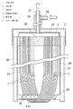
図1は本発明の実施の形態の一例を示すものである。中空糸膜1はポリエチレン、ポリフッ化ビニリデン、ポリテトラフルオロエチレン、ポリアクルロニトリル、ポルスルホンなど従来から公知の任意の材質のものを用いることができるものであり、孔径なども特に限定されるものではない。そして中空糸膜1を所定の隙間を介して複数本束ね、この中空糸膜1の束をU字状に屈曲し、中空糸膜1の両端部を接着剤に埋入させた状態で接着剤を硬化させることによって、各中空糸膜1の両端部を接着部20で結合するようにしてある。各中空糸膜1の両端の開口部は接着部20の上面に開口させてある。   FIG. 1 shows an example of an embodiment of the present invention. The hollow fiber membrane 1 can be made of any conventionally known material such as polyethylene, polyvinylidene fluoride, polytetrafluoroethylene, polyacrylonitrile, porsulfone, and the pore diameter is not particularly limited. Absent. Then, a plurality of hollow fiber membranes 1 are bundled through a predetermined gap, the bundle of hollow fiber membranes 1 is bent into a U shape, and both ends of the hollow fiber membrane 1 are embedded in the adhesive. Is cured so that both ends of each hollow fiber membrane 1 are bonded together by the adhesive portion 20. Openings at both ends of each hollow fiber membrane 1 are opened on the upper surface of the bonding portion 20.

固定部2は下面が開口する通水部3と、通水部3の上面の外周面を囲むエアー導入部10とから二重構造に形成してあり、通水部3の上面の中央部に、通水部3内と連通する排水筒22が上方に突出してある。またこの排水筒22の外側を囲むようにエアー供給筒23がエアー導入部10の上面に突設してある。エアー供給筒23内はエアー導入部10内に連通しているものであり、エアー導入筒23の外周に接続口24が設けてある。   The fixing portion 2 is formed in a double structure from a water passage portion 3 whose lower surface is open and an air introduction portion 10 surrounding the outer peripheral surface of the upper surface of the water passage portion 3. A drain tube 22 communicating with the inside of the water flow portion 3 protrudes upward. An air supply cylinder 23 projects from the upper surface of the air introduction part 10 so as to surround the outside of the drain cylinder 22. The air supply cylinder 23 communicates with the air introduction unit 10, and a connection port 24 is provided on the outer periphery of the air introduction cylinder 23.

そして通水部3の下面の開口を塞ぐように接着部20を嵌め込んで接着等して固定することによって、U字状に屈曲した各中空糸膜1の両端部が固定部2に固定されるようにしてあり、中空糸膜1の両端の開口部は通水部3内に開口している。このように中空糸膜1は両端部を固定部2に片持ちで固定した状態で、両端部が上、屈曲部が下となる姿勢で配置されるものである。   Then, the both ends of each hollow fiber membrane 1 bent in a U-shape are fixed to the fixing part 2 by fitting the adhesive part 20 so as to close the opening on the lower surface of the water passing part 3 and fixing it. In this way, the openings at both ends of the hollow fiber membrane 1 are open in the water passage 3. As described above, the hollow fiber membrane 1 is arranged in a posture in which both end portions are fixed to the fixing portion 2 in a cantilevered state and both end portions are on the upper side and the bent portion is on the lower side.

また通水部3を囲むエアー導入部10の下面は閉じられているが、その2箇所において一対のフレーム支柱26が下方へ突設してある。このフレーム支柱26は内部をエアー流路27としたパイプ状に形成してあり、上端を開口させてエアー流路27をエアー導入部10内と連通させると共に、下端は閉塞してある。この一対のフレーム支柱26の下端部間に端部保持部材4を水平に配置し、端部保持部材4の両端部を各フレーム支柱26に接続固定してある。この端部保持部材4は中空糸膜1の束の屈曲した側の端部の内側に串刺しするように挿通してあり、片持ち状態で固定された中空糸膜1の自由端となった屈曲部を端部保持部材4で保持することができるものである。そしてこの端部保持部材4は中空のパイプ状に形成し、中空内部をフレーム支柱26のエアー流路27内に連通させてあり、また散気孔28を穿設することによって、端部保持部材4を散気管5として形成するようにしてある。   Moreover, the lower surface of the air introduction part 10 surrounding the water flow part 3 is closed, but a pair of frame struts 26 project downward at the two locations. The frame column 26 is formed in a pipe shape having an air flow path 27 inside, and the upper end is opened to allow the air flow path 27 to communicate with the inside of the air introduction unit 10 and the lower end is closed. The end holding member 4 is horizontally disposed between the lower ends of the pair of frame columns 26, and both ends of the end holding member 4 are connected and fixed to the frame columns 26. This end holding member 4 is inserted so as to be stabbed inside the bent side end of the bundle of hollow fiber membranes 1 and is a bent end that is a free end of the hollow fiber membrane 1 fixed in a cantilever state. The portion can be held by the end holding member 4. The end holding member 4 is formed in a hollow pipe shape, the hollow interior is communicated with the air flow path 27 of the frame column 26, and the end holding member 4 is formed by drilling a diffuser hole 28. Is formed as a diffuser tube 5.

上記のように形成される本発明に係る膜モジュールは、膜分離式水浄化装置の浄化槽内に設置して使用されるものであり、固定部2の排水筒22には吸引ポンプなどを設けた吸引排出配管(図示省略)が接続してあり、またエアー供給筒23の接続口24には送風器などを設けた送風配管(図示省略)が接続してある。そして吸引排出配管の吸引ポンプを作動させると、排水筒22を通して通水部3内は吸引・減圧状態になるので、浄化槽内において活性汚泥で浄化された水は、中空糸膜1をその外周から内周へと通過して中空糸膜1内に流入し、さらに中空糸膜1内から通水部3に流入して集水された後、排水筒22を通して吸引排出配管から排出されるものである。   The membrane module according to the present invention formed as described above is used by being installed in the septic tank of the membrane separation type water purification device, and the drain tube 22 of the fixed part 2 is provided with a suction pump or the like. A suction / discharge pipe (not shown) is connected, and a blower pipe (not shown) provided with a blower or the like is connected to the connection port 24 of the air supply cylinder 23. When the suction pump of the suction / discharge pipe is operated, the inside of the water passage 3 is sucked and depressurized through the drain tube 22, so that the water purified by the activated sludge in the septic tank moves the hollow fiber membrane 1 from its outer periphery. It passes through the inner periphery and flows into the hollow fiber membrane 1, and further flows into the water passage 3 from the hollow fiber membrane 1 and is collected, and then is discharged from the suction / discharge pipe through the drain tube 22. is there.

ここで、膜モジュールの中空糸膜1の屈曲した側の端部は自由端となっているために、中空糸膜1の束においてこの屈曲側の端部が絡まり合うと、中空糸膜1への水の通水効率が低下し、また絡まり合った中空糸膜1の隙間内に活性汚泥が溜まって汚れが付着し易いが、上記のように、中空糸膜1の屈曲した側の端部の内側に端部保持部材4を挿通してあるので、中空糸膜1の屈曲した側の端部の束は端部保持部材4で拘束した状態に保持されている。従って、中空糸膜1に絡まり合いが生じることを防ぐことができるものであり、中空糸膜1への水の通水効率が低下することを防止できると共に、絡まり合った部分に活性汚泥が溜まることを未然に防止することができるものである。   Here, since the end of the membrane module on the bent side of the hollow fiber membrane 1 is a free end, when the end of the bent side of the bundle of hollow fiber membranes 1 is entangled, the hollow fiber membrane 1 However, as described above, the end of the hollow fiber membrane 1 on the bent side is likely to be contaminated with the activated sludge that accumulates in the gaps of the tangled hollow fiber membranes 1. Since the end holding member 4 is inserted inside the end bundle, the end bundle on the bent side of the hollow fiber membrane 1 is held in a state constrained by the end holding member 4. Accordingly, it is possible to prevent the entanglement of the hollow fiber membrane 1 and prevent the water flow efficiency of the hollow fiber membrane 1 from being lowered, and the activated sludge is accumulated in the entangled portion. This can be prevented in advance.

また本発明では、この中空糸膜1の屈曲した下端部を保持する端部保持部材4は、散気孔28を設けた散気管5として形成されており、送風配管からエアーがエアー供給筒23、エアー導入部10、フレーム支柱26のエアー流路27を通して、散気管5内に供給されている。そしてエアーが端部保持部材4で形成される散気管5にこのように供給されて、散気孔28からエアーが散気されると、この散気エアーは中空糸膜1に吹き当てられることになり、中空糸膜1を振動させるようになっている。従って、中空糸膜1の表面に活性汚泥が堆積して汚れが付着することを防止することができ、中空糸膜1に目詰まりが発生することを低減することができるものである。しかも、中空糸膜1の自由端となっている屈曲側の端部は散気管5で保持されているので、中空糸膜1に絡まり合いが生じるようなことなく、中空糸膜1にエアーを散気して目詰まり防止を行なうことができるものである。   Moreover, in this invention, the edge part holding member 4 holding the bent lower end part of this hollow fiber membrane 1 is formed as the air diffusion pipe | tube 5 which provided the air diffusion hole 28, and air is supplied from the air supply pipe 23 to the air supply cylinder 23, The air is supplied into the diffuser pipe 5 through the air introduction part 10 and the air flow path 27 of the frame column 26. Then, when air is supplied to the diffuser tube 5 formed by the end holding member 4 and air is diffused from the diffuser holes 28, the diffused air is blown against the hollow fiber membrane 1. Thus, the hollow fiber membrane 1 is vibrated. Therefore, it is possible to prevent activated sludge from accumulating on the surface of the hollow fiber membrane 1 to prevent dirt from adhering, and to reduce the occurrence of clogging in the hollow fiber membrane 1. Moreover, since the end of the bent side that is the free end of the hollow fiber membrane 1 is held by the air diffusing tube 5, the hollow fiber membrane 1 is not entangled and air is supplied to the hollow fiber membrane 1. It is possible to prevent clogging by aeration.

またここで、固定部2は上記のように通水部3の上面の外周面をエアー導入部10で囲む二重構造に形成してあるので、外力の作用等で固定部2の外郭が破損された場合、外郭の破損でエアー導入部10の内部は露出しても、通水部3の内部が露出することはない。従って、固定部2の外郭が破損されてもエアー導入部10からエアーが漏れる程度であり、固定部2の外郭の破損で通水部3の内部が露出する場合のように、浄化槽内の浄化されていない水や活性汚泥が破損箇所から通水部3内に流入し、通水部3から吸引排出配管を通して外部に排出されてしまうような事故を防ぐことができるものである。   Here, since the fixing portion 2 is formed in a double structure in which the outer peripheral surface of the upper surface of the water passing portion 3 is surrounded by the air introduction portion 10 as described above, the outline of the fixing portion 2 is damaged due to the action of an external force or the like. In this case, even if the inside of the air introduction part 10 is exposed due to the damage of the outer shell, the inside of the water passage part 3 is not exposed. Therefore, even if the outer shell of the fixed portion 2 is damaged, the air is leaked from the air introduction portion 10, and the inside of the water passage portion 3 is exposed due to the outer shell of the fixed portion 2 being damaged. It is possible to prevent an accident in which untreated water or activated sludge flows into the water passage 3 from the damaged portion and is discharged to the outside from the water passage 3 through the suction discharge pipe.

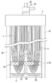
図2は本発明の他の実施の形態を示すものであり、端部保持部材4として形成される散気管5は一対のフレーム支柱26の下端よりやや上の位置に取り付けて、中空糸膜1の束の屈曲した下端部の内側に挿通してある。そして中空糸膜1の屈曲した下端よりも下側位置において散気管5と平行に補助散気管6が配置してあり、補助散気管6は一対のフレーム支柱26の下端間に取り付けてある。補助散気管6は中空パイプとして形成してあって、中空内部をフレーム支柱26のエアー流路27に連通させてあり、多数の散気孔28が設けてある。補助散気管6の散気孔28は散気管5の散気孔28より多い個数で設けてあり、散気管5よりも補助散気管6の散気量が多くなるようにしてある。また図2の実施の形態では散気管5と補助散気管6の中央部間に縦散気管30が架け渡して取り付けてある。縦散気管30は中空パイプとして形成してあって、散気管5及び補助散気管6と内部同士を連通させてあり、多数の散気孔28が設けてある。その他の構成は図1のものと同じである。   FIG. 2 shows another embodiment of the present invention. A diffuser tube 5 formed as an end holding member 4 is attached to a position slightly above the lower ends of a pair of frame struts 26 so that the hollow fiber membrane 1 Is inserted inside the bent lower end of the bundle. An auxiliary air diffuser 6 is arranged in parallel with the air diffuser 5 at a position below the bent lower end of the hollow fiber membrane 1, and the auxiliary air diffuser 6 is attached between the lower ends of the pair of frame columns 26. The auxiliary air diffusion pipe 6 is formed as a hollow pipe, and the hollow interior is communicated with the air flow path 27 of the frame column 26, and a large number of air diffusion holes 28 are provided. The air diffuser 28 of the auxiliary air diffuser 6 is provided in a larger number than the air diffuser 28 of the air diffuser 5 so that the amount of air diffused in the auxiliary air diffuser 6 is larger than that of the air diffuser 5. In the embodiment shown in FIG. 2, a vertical air diffuser 30 is installed between the air diffuser 5 and the central portion of the auxiliary air diffuser 6. The vertical air diffuser 30 is formed as a hollow pipe, communicates with the air diffuser 5 and the auxiliary air diffuser 6 inside, and has a large number of air diffusers 28. Other configurations are the same as those in FIG.

図2のものでは、散気管5からの他に、補助散気管6からもエアーが散気され、この散気エアーは中空糸膜1に均一に吹き当てられるようになっている。従って、中空糸膜1に目詰まりが発生することを低減する効果をより高く得ることができるものである。さらに縦散気管30から散気されるエアーも中空糸膜1に均一に吹き当てられるので、目詰まり防止効果を一層高く得ることができるものである。また縦散気管30は散気管5と補助散気管6の中央部間に縦に配置されているので、中空糸膜1の束の屈曲した下端部の内側に散気管5を挿通するにあたって、中空糸膜1の束は縦散気管30で左右二つの小さな束に分けることができるものであり、中空糸膜1がより絡み合い難くなるものである。   In the case of FIG. 2, air is diffused from the auxiliary diffuser tube 6 in addition to the diffuser tube 5, and this diffused air is uniformly blown to the hollow fiber membrane 1. Therefore, the effect of reducing the occurrence of clogging in the hollow fiber membrane 1 can be obtained higher. Furthermore, since the air diffused from the longitudinal air diffuser 30 is also uniformly blown to the hollow fiber membrane 1, the effect of preventing clogging can be further enhanced. In addition, since the vertical air diffuser 30 is disposed vertically between the central portions of the air diffuser 5 and the auxiliary air diffuser 6, the hollow air diffuser 5 is hollow when inserted through the bent lower end of the bundle of the hollow fiber membranes 1. The bundle of the yarn membranes 1 can be divided into two small bundles on the left and right by the longitudinal air diffuser 30, and the hollow fiber membranes 1 are more difficult to be entangled.

図3の実施の形態では、図2のように平行に配置される散気管5と補助散気管6の間に多数の通孔32を設けた多孔板33を取り付けるようにしてある。そして中空糸膜1の束の、各中空糸膜1は一本ずつ多孔板33の各通孔32に通してある。その他の構成は図2のものと同じである。従ってこの実施の形態では各中空糸膜1は多孔板33の通孔32で分離されており、中空糸膜1が絡まり合うことを確実に防ぐことができると共に、中空糸膜1同士が密着することを防いで、活性汚泥が密着部分に溜まって付着することを防ぐことができるものである。   In the embodiment of FIG. 3, a perforated plate 33 provided with a large number of through holes 32 between the diffuser tubes 5 and the auxiliary diffuser tubes 6 arranged in parallel as shown in FIG. 2 is attached. Each hollow fiber membrane 1 in the bundle of hollow fiber membranes 1 is passed through each through hole 32 of the porous plate 33 one by one. Other configurations are the same as those in FIG. Therefore, in this embodiment, the hollow fiber membranes 1 are separated by the through holes 32 of the porous plate 33, so that the hollow fiber membranes 1 can be reliably prevented from being entangled and the hollow fiber membranes 1 are in close contact with each other. This prevents the activated sludge from accumulating and adhering to the close contact portion.

図4の実施の形態では、エアー流路27を有するフレーム支柱26を等間隔で4本設けるようにしてある。そして一本おきの一対のフレーム支柱26の下端部間に端部保持部材4となる散気管5を取り付けると共に、この散気管5の下側において、他の一本おきの一対のフレーム支柱26の下端間に補助散気管6を取り付けるようにしてあり、散気管5と補助散気管6とは平面視で直交する交差配置にしてある。また図4の実施の形態では、散気管5と補助散気管6の交差部間に縦散気管30が取り付けてある。その他の構成は、図2のものと同じである。   In the embodiment of FIG. 4, four frame columns 26 having air flow paths 27 are provided at equal intervals. And while attaching the diffuser pipe | tube 5 used as the edge part holding member 4 between the lower end parts of every other pair of frame support | pillar 26, on the lower side of this diffuser pipe | tube 5, other pair of every other frame support | pillar 26 of a pair. The auxiliary air diffusing tube 6 is attached between the lower ends, and the air diffusing tube 5 and the auxiliary air diffusing tube 6 are arranged so as to intersect at right angles in a plan view. In the embodiment shown in FIG. 4, a vertical air diffuser 30 is attached between the intersections of the air diffuser 5 and the auxiliary air diffuser 6. Other configurations are the same as those in FIG.

図5及び図6は本発明の他の実施の形態を示すものであり、エアー流路27を有するフレーム支柱26を等間隔で4本設けるようにしてある。そして一本おきの一対のフレーム支柱26の下端部間に図2の実施の形態と同様に、散気管5と補助散気管6とを上下平行に取り付けてある。またこの散気管5と補助散気管6との間において、他の一本おきの一対のフレーム支柱26の下端間に第2補助散気管7を取り付けるようにしてあり、第2補助散気管7は散気管5と補助散気管6とに平面視で直交する交差配置にしてある。第2補助散気管7は中空パイプとして形成してあって、中空内部をフレーム支柱26のエアー流路27に連通させてあり、多数の散気孔28が設けてある。第2補助散気管7の散気孔28は散気管5や補助散気管6の散気孔28よりも少ない個数で設けてあり、従って散気量は補助散気管6、散気管5、第2補助散気管7の順に少なくなるようにしてある。また図5、図6の実施の形態では、散気管5と第2補助散気管7の交差部間及び第2補助散気管7と補助散気管6の交差部間にそれぞれ縦散気管30が取り付けてあり、縦散気管30内は散気管5内、補助散気管6内、第2補助散気管7内にそれぞれ連通させてある。その他の構成は、図1、図2、図4のものと同じである。   5 and 6 show another embodiment of the present invention, in which four frame columns 26 having air flow paths 27 are provided at equal intervals. In the same manner as in the embodiment of FIG. 2, the air diffuser 5 and the auxiliary air diffuser 6 are attached vertically between the lower ends of every other pair of frame columns 26. Further, between the diffuser pipe 5 and the auxiliary diffuser pipe 6, a second auxiliary diffuser pipe 7 is attached between the lower ends of every other pair of frame supports 26. The air diffuser 5 and the auxiliary air diffuser 6 are arranged so as to intersect perpendicularly in plan view. The second auxiliary diffuser tube 7 is formed as a hollow pipe, and the hollow interior is communicated with the air flow path 27 of the frame column 26, and a large number of diffuser holes 28 are provided. The diffuser holes 28 of the second auxiliary diffuser tube 7 are provided in a smaller number than the diffuser holes 28 of the diffuser tube 5 and the auxiliary diffuser tube 6, and therefore the amount of diffused air is the auxiliary diffuser tube 6, the diffuser tube 5, and the second auxiliary diffuser. The trachea 7 decreases in order. In the embodiment of FIGS. 5 and 6, the vertical air diffuser 30 is attached between the intersection of the air diffuser 5 and the second auxiliary air diffuser 7 and between the intersection of the second auxiliary air diffuser 7 and the auxiliary air diffuser 6. The longitudinal diffuser 30 is communicated with the diffuser 5, the auxiliary diffuser 6, and the second auxiliary diffuser 7. Other configurations are the same as those in FIGS. 1, 2, and 4.

このものでは、散気管5と補助散気管6の他に、第2補助散気管7からもエアーが散気され、この散気エアーは中空糸膜1に均一に吹き当てられるようになっている。従って、中空糸膜1に目詰まりが発生することを低減する効果をより高く得ることができるものである。さらに縦散気管30から散気されるエアーも中空糸膜1に均一に吹き当てられるので、目詰まり防止効果を一層高く得ることができるものである。また中空糸膜1の束は縦散気管30で左右二つの小さな束に分けられるものであり、中空糸膜1がより絡み合い難くなるものである。   In this case, air is diffused from the second auxiliary diffuser tube 7 in addition to the diffuser tube 5 and the auxiliary diffuser tube 6, and this diffused air is uniformly blown to the hollow fiber membrane 1. . Therefore, the effect of reducing the occurrence of clogging in the hollow fiber membrane 1 can be obtained higher. Furthermore, since the air diffused from the longitudinal air diffuser 30 is also uniformly blown to the hollow fiber membrane 1, the effect of preventing clogging can be further enhanced. Further, the bundle of the hollow fiber membranes 1 is divided into two small bundles on the left and right by the vertical air diffuser tube 30, and the hollow fiber membranes 1 are more difficult to be entangled.

図7の実施の形態は、図5及び図6のものにおいて、平行に配置される散気管5と補助散気管6の間に、図3と同様に多数の通孔32を設けた多孔板33を取り付けるようにしてある。そして中空糸膜1の束の、各中空糸膜1は一本ずつ多孔板33の各通孔32に通してある。その他の構成は図2のものと同じである。従ってこの実施の形態では中空糸膜1の束を縦散気管30で左右二つの小さな束に分け、さらに各中空糸膜1を多孔板33の通孔32で分離することができるものである。   The embodiment of FIG. 7 is the same as that of FIG. 5 and FIG. 6, and a perforated plate 33 in which a large number of through holes 32 are provided between the air diffuser pipe 5 and the auxiliary air diffuser pipe 6 arranged in parallel. Is supposed to be attached. Each hollow fiber membrane 1 in the bundle of hollow fiber membranes 1 is passed through each through hole 32 of the porous plate 33 one by one. Other configurations are the same as those in FIG. Therefore, in this embodiment, the bundle of the hollow fiber membranes 1 can be divided into two small bundles on the left and right by the vertical diffuser tube 30, and each hollow fiber membrane 1 can be separated by the through holes 32 of the perforated plate 33.

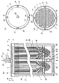
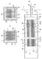
図8は本発明の他の実施の形態を示すものであり、上記のように両端部を固定部2に固定した中空糸膜1の束は、下面が開口する角筒状の筒容器35内に取り付けてある。そしてこの実施の形態では散気管5を、同一高さで平行に配置される複数本の上散気管8と、この上散気管8の下方位置において、同一高さで平行に配置される複数本の下散気管9とで形成するようにしてある。筒容器35の内面の対向する二箇所にそれぞれ上エアー供給筒36が、この上エアー供給路36の下側位置において、筒容器35の内面の対向する他の二箇所にそれぞれ下エアー供給筒37がそれぞれ設けてあり、上エアー供給筒36や下エアー供給筒37には送風器などを設けた送風配管(図示省略)に接続される接続筒38が突設してある。上散気管8の両端は上エアー供給筒36に、下散気管9の両端は下エアー供給筒37にそれぞれ取り付けられるものであり、各上散気管8と各下散気管9とは平面視で直交するように交差させてある。散気孔28は上散気管8と下散気管9の交差しない箇所に設けてあり、送風器から送風されたエアーは、上エアー供給筒36から上散気管8に、下エアー供給筒37から下散気管9にそれぞれ送られ、上散気管8や下散気管9の散気孔28から散気されるものである。   FIG. 8 shows another embodiment of the present invention, and the bundle of hollow fiber membranes 1 having both ends fixed to the fixing portion 2 as described above is contained in a rectangular tube-shaped tube container 35 whose bottom surface is open. It is attached to. In this embodiment, the diffuser tubes 5 are a plurality of upper diffuser tubes 8 arranged in parallel at the same height, and a plurality of diffuser tubes arranged in parallel at the same height at a position below the upper diffuser tube 8. And the lower air diffuser 9. Upper air supply cylinders 36 are respectively provided at two opposite positions on the inner surface of the cylindrical container 35, and lower air supply cylinders 37 are respectively provided at two other positions opposite to the inner surface of the cylindrical container 35 at a lower position of the upper air supply path 36. Each of the upper air supply cylinder 36 and the lower air supply cylinder 37 is provided with a connecting cylinder 38 projecting from a ventilation pipe (not shown) provided with a blower or the like. Both ends of the upper air diffuser 8 are attached to the upper air supply tube 36, and both ends of the lower air diffuser 9 are respectively attached to the lower air supply tube 37. The upper air diffuser 8 and the lower air diffuser 9 are viewed in plan view. Crossed so as to be orthogonal. The air diffuser hole 28 is provided at a location where the upper air diffuser tube 8 and the lower air diffuser tube 9 do not intersect, and the air blown from the blower is sent from the upper air supply tube 36 to the upper air diffuser tube 8 and from the lower air supply tube 37 to the lower air diffuser. The air is sent to the air diffuser 9 and is diffused from the air diffuser holes 28 of the upper air diffuser 8 and the lower air diffuser 9.

また、これらの上散気管8と下散気管9を両端部を固定部2に固定した中空糸膜1の束の屈曲した下端部の内側に挿通し、中空糸膜1の屈曲端部を保持するようにしてあるが、上散気管8と下散気管9の各交差部分に一対の中空糸膜1が保持されるようにしてある。すなわち図8(b)のように、上散気管8と下散気管9の各交差部分には平面視で4つの入隅部が形成されるが、一対の中空糸膜1のうち一方の中空糸膜1が、上散気管8と下散気管9を介して対向する一対の入隅部に配置され、且つ他方の中空糸膜1が、上散気管8と下散気管9を介して対向する他の一対の入隅部に配置されるようにしてあり、図8(c)のようにこの一対の中空糸膜1は下散気管9の下側でクロスされる。このように一対の中空糸膜1をクロスさせるようにして上散気管8と下散気管9を中空糸膜1の屈曲部の内側に挿通することによって、中空糸膜1は相互に密着することなく中空糸膜1の間に隙間を形成することができるものであり、密着した中空糸膜1間に活性汚泥などの汚れが溜まって蓄積するようなことを防ぐことができるものである。また上散気管8や下散気管9の散気孔28から各中空糸膜1に均等にエアーを散気することができ、目詰まり防止の効果を高く得ることができるものである。   Further, the upper air diffuser 8 and the lower air diffuser 9 are inserted into the inside of the bent lower end of the bundle of hollow fiber membranes 1 whose both ends are fixed to the fixed part 2, and the bent end of the hollow fiber film 1 is held. However, a pair of hollow fiber membranes 1 is held at each intersection of the upper air diffuser tube 8 and the lower air diffuser tube 9. That is, as shown in FIG. 8 (b), four intersecting corners are formed in each crossing portion of the upper air diffuser tube 8 and the lower air diffuser tube 9 in plan view, but one of the hollow fiber membranes 1 is hollow. The yarn membrane 1 is disposed at a pair of corners facing each other via the upper air diffuser tube 8 and the lower air diffuser tube 9, and the other hollow fiber membrane 1 is opposed via the upper air diffuser tube 8 and the lower air diffuser tube 9. The pair of hollow fiber membranes 1 are crossed under the lower air diffuser tube 9 as shown in FIG. 8C. By inserting the upper air diffuser tube 8 and the lower air diffuser tube 9 inside the bent portion of the hollow fiber membrane 1 so as to cross the pair of hollow fiber membranes 1 in this way, the hollow fiber membranes 1 are in close contact with each other. It is possible to form a gap between the hollow fiber membranes 1 and prevent dirt such as activated sludge from accumulating and accumulating between the closely attached hollow fiber membranes 1. Further, air can be uniformly diffused from the air diffuser holes 28 of the upper air diffuser tube 8 and the lower air diffuser tube 9 to each hollow fiber membrane 1, and the effect of preventing clogging can be obtained highly.

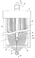
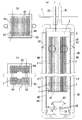
図9は膜モジュールの参考例を示すものであり、中空糸膜1は上記と同様にU字状に屈曲して両端部を接着部20で接着固定してある。固定部2は筒体40の外側に外筒41を配した二重構造に形成してあり、筒体40内に中空糸膜1を配置して筒体40の上部内に接着部20を取り付けることによって、接着部20と筒体40内との間に通水部3が形成されるようにしてある。この通水部3には排水筒22が突出してあり、排水筒22には吸引ポンプなどを設けた吸引排出配管(図示省略)が接続してある。また外筒41と筒体40との間にエアー導入部10が形成されるものであり、排水筒22の外側を囲むようにエアー供給筒23がエアー導入部10の上面に突設してあって、エアー供給筒23には送風器などを設けた送風配管(図示省略)が接続してある。外筒41はその下端部を筒体40の下端部より下方へ延出してあり、外筒41の下部内においてエアー導入部10を開口させるようにしてある。そして外筒41と筒体40の間に筒状の連通口42を設けて、筒体40内を外筒41の外側に開口させてある。   FIG. 9 shows a reference example of the membrane module. The hollow fiber membrane 1 is bent in a U-shape in the same manner as described above, and both ends thereof are bonded and fixed by the bonding portions 20. The fixing part 2 is formed in a double structure in which an outer cylinder 41 is arranged outside the cylinder body 40, the hollow fiber membrane 1 is disposed in the cylinder body 40 and the adhesive part 20 is attached in the upper part of the cylinder body 40. Thus, the water passing portion 3 is formed between the bonding portion 20 and the inside of the cylindrical body 40. A drain tube 22 protrudes from the water passage 3, and a suction discharge pipe (not shown) provided with a suction pump or the like is connected to the drain tube 22. Further, the air introduction part 10 is formed between the outer cylinder 41 and the cylinder body 40, and the air supply cylinder 23 projects from the upper surface of the air introduction part 10 so as to surround the outside of the drainage cylinder 22. The air supply tube 23 is connected to a blower pipe (not shown) provided with a blower or the like. The outer cylinder 41 has a lower end extending downward from the lower end of the cylinder 40, and the air introduction part 10 is opened in the lower part of the outer cylinder 41. A cylindrical communication port 42 is provided between the outer cylinder 41 and the cylinder 40, and the inside of the cylinder 40 is opened to the outside of the outer cylinder 41.

また、筒体40の下部内には、同一高さで平行に配置される複数本の上保持シャフト43と、この上保持シャフト43の下方位置において、同一高さで平行に配置される複数本の下保持シャフト44が取り付けてあり、各上保持シャフト43と各下保持シャフト44とは平面視で直交するように交差させてある。そして上保持シャフト43と下保持シャフト44を両端部を中空糸膜1の束の屈曲した下端部の内側に挿通し、中空糸膜1の屈曲端部を保持するようにしてあるが、上保持シャフト43と下保持シャフト44の各交差部分に一対の中空糸膜1が保持されるようにし、図9(b)(c)に示すように、図8(b)(c)の場合と同様にして、この一対の中空糸膜1が下保持シャフト44の下側でクロスされるようにしてある。   Further, in the lower part of the cylindrical body 40, a plurality of upper holding shafts 43 arranged in parallel at the same height, and a plurality of pieces arranged in parallel at the same height at a position below the upper holding shaft 43. The lower holding shafts 44 are attached, and the upper holding shafts 43 and the lower holding shafts 44 cross each other so as to be orthogonal to each other in plan view. The upper holding shaft 43 and the lower holding shaft 44 are inserted into both ends of the bent lower end portion of the bundle of hollow fiber membranes 1 to hold the bent end portion of the hollow fiber membrane 1. A pair of hollow fiber membranes 1 is held at each intersection of the shaft 43 and the lower holding shaft 44, and as shown in FIGS. 9B and 9C, the same as in FIGS. 8B and 8C. Thus, the pair of hollow fiber membranes 1 are crossed on the lower side of the lower holding shaft 44.

上記のように形成される膜モジュールは、活性汚泥を含む水のレベルLが図9(a)のようになるように浄化槽内に設置されるものである。そして送風配管からエアーがエアー導入部10に供給されると、エアーは図9(a)のa矢印のようにエアー導入部10の下端の開口から筒体40内に回り込んで入るので、この流れによって活性汚泥を含む水がb矢印のように上昇して筒体40内に入り込み、連通口42を通してc矢印のように外部に流出するという流れが生じ、この速い流れで中空糸膜1の間に活性汚泥などの汚れが詰まって付着することを防ぐことができるものである。また、上保持シャフト43や下保持シャフト44は細い棒として形成することができるので、間隔を大きくとることができ、活性汚泥を含む水が通過し易くなって汚れの付着防止効果を高く得ることができるものである。 Membrane module is formed as described above are those levels L 1 of water containing activated sludge is placed in the septic tank so as to become in Figure 9 (a). And when air is supplied to the air introduction part 10 from a ventilation pipe, since air will enter into the cylinder 40 from the opening of the lower end of the air introduction part 10 as shown by a arrow in FIG. As a result of the flow, water containing activated sludge rises as shown by the arrow b and enters the cylinder 40, and flows out to the outside as shown by the arrow c through the communication port 42. With this fast flow, the hollow fiber membrane 1 It is possible to prevent dirt such as activated sludge from clogging and adhering between them. Further, since the upper holding shaft 43 and the lower holding shaft 44 can be formed as thin rods, the interval can be increased, and water containing activated sludge can be easily passed and the effect of preventing the adhesion of dirt can be enhanced. It is something that can be done.

図10は膜モジュールの他の参考例を示すものであり、固定部2は外筒41を備えない筒体40だけの一重構造に形成してある。筒体40内に中空糸膜1を取り付ける構成は図9のものと同じである。   FIG. 10 shows another reference example of the membrane module, in which the fixing portion 2 is formed in a single structure having only the cylinder 40 that does not include the outer cylinder 41. The structure for attaching the hollow fiber membrane 1 in the cylindrical body 40 is the same as that shown in FIG.

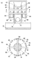
そして筒体40の両側の外面に沿って一対のエアー供給管46が垂下してあり、各エアー供給管46の上端は接続筒47に接続してあって、接続筒47には送風器などを設けた送風配管(図示省略)が接続してある。各エアー供給管46の下端は接続管72に接続してあり、接続管72にはエアー吐出管79を上向きに突出させて設けてある。そして図11に示すように、このエアー吐出管79内には接続管72に連通する散気孔73を内周に形成した弁座74が設けてある。エアー吐出管79にはその内外に貫通する横棒80が取り付けてあり、横棒80の両端部はエアー吐出管79の外方へ突出している。横棒80は2本ずつ十字に交差させて設けてある。この横棒80の下側において弁座74には弁球81が上下動自在に取り付けてあり、散気孔73を弁球81で開閉できるようにしてある。またエアー吐出管79の上部を下面が開口するトラップ容器82で覆ってある。エアー吐出管79の上底面には円錐台形状の弁蓋83が設けてあり、弁蓋83でエアー吐出管79の上端開口を開閉できるようにしてある。またトラップ容器82の周壁には縦長のスライド孔84が穿設してあり、このスライド孔84に横棒80の端部が差し込んである。従って横棒80に対してスライド孔84が上下できる範囲で、トラップ容器82は上下動されるものである。さらにトラップ容器82の周壁にはその周方向に亘る複数箇所に散気スリット85が穿設してあり、各散気スリット85はトラップ容器82の周壁の下端縁で開放されるようにしてある。   A pair of air supply pipes 46 hang down along the outer surfaces on both sides of the cylinder 40, and the upper ends of the air supply pipes 46 are connected to the connection cylinders 47. A provided air pipe (not shown) is connected. The lower end of each air supply pipe 46 is connected to a connection pipe 72, and an air discharge pipe 79 is provided on the connection pipe 72 so as to protrude upward. As shown in FIG. 11, a valve seat 74 is provided in the air discharge pipe 79. The valve seat 74 has an air diffuser 73 communicating with the connecting pipe 72 formed on the inner periphery thereof. The air discharge pipe 79 is attached with a horizontal bar 80 penetrating inside and outside thereof, and both end portions of the horizontal bar 80 protrude outward of the air discharge pipe 79. Two horizontal bars 80 are provided crossing each other in a cross. On the lower side of the horizontal bar 80, a valve ball 81 is attached to the valve seat 74 so as to be movable up and down, and the air diffuser 73 can be opened and closed by the valve ball 81. The upper part of the air discharge pipe 79 is covered with a trap container 82 whose lower surface is open. A frustoconical valve lid 83 is provided on the upper bottom surface of the air discharge pipe 79 so that the upper end opening of the air discharge pipe 79 can be opened and closed by the valve lid 83. A vertically long slide hole 84 is formed in the peripheral wall of the trap container 82, and the end of the horizontal bar 80 is inserted into the slide hole 84. Therefore, the trap container 82 is moved up and down within a range in which the slide hole 84 can be moved up and down with respect to the horizontal bar 80. Further, the peripheral wall of the trap container 82 is provided with diffuser slits 85 at a plurality of locations in the circumferential direction, and each diffuser slit 85 is opened at the lower end edge of the peripheral wall of the trap container 82.

このものにあって、送風器から空気などの気体が接続管72に送られると、その送風圧で弁球81が押し上げられて散気孔73が開口し、さらに弁蓋83がトラップ容器82と共に押し上げられ、気体は散気孔73からエアー吐出管79を通してトラップ容器82内に流入して、図10(a)のa矢印のように散気スリット85から散気される。散気スリット85はトラップ容器82の周壁の下端縁で開放された形態であるので、散気スリット85が活性汚泥で詰まり難くなっている。また送風器の作動が停止して気体が送られなくなると、弁球81が自重で落下して散気孔73が塞がれると共に、トラップ容器82が水圧で押し下げられてエアー吐出管79の上端開口が弁蓋83で塞がれることになり、浄化槽内の活性汚泥がエアー吐出管79及び接続管72を通してエアー供給管46へと逆流することを防止することができ、これらの管内に活性汚泥が浸入して詰まることを防ぐことができるものである。ここで、活性汚泥の逆流は、トラップ容器82とエアー吐出管79との間のトラップ効果と、弁蓋83によるエアー吐出管79の閉塞と、弁球81による散気孔73の閉塞とで、三重に防止されるようになっているものであり、活性汚泥が逆流することを確実に防ぐことができるものである。   In this case, when a gas such as air is sent from the blower to the connection pipe 72, the valve ball 81 is pushed up by the blown pressure to open the air diffusion hole 73, and the valve lid 83 is pushed up together with the trap container 82. Then, the gas flows into the trap container 82 from the diffuser hole 73 through the air discharge pipe 79 and is diffused from the diffuser slit 85 as indicated by an arrow a in FIG. Since the diffuser slit 85 is open at the lower end edge of the peripheral wall of the trap container 82, the diffuser slit 85 is less likely to be clogged with activated sludge. When the operation of the air blower is stopped and gas cannot be sent, the valve ball 81 falls by its own weight and the air diffuser 73 is closed, and the trap container 82 is pushed down by water pressure to open the upper end of the air discharge pipe 79. Is blocked by the valve lid 83, and the activated sludge in the septic tank can be prevented from flowing back to the air supply pipe 46 through the air discharge pipe 79 and the connecting pipe 72, and the activated sludge is contained in these pipes. It can prevent clogging due to intrusion. Here, the reverse flow of the activated sludge is triple due to the trap effect between the trap container 82 and the air discharge pipe 79, the blockage of the air discharge pipe 79 by the valve lid 83, and the blockage of the air diffusion hole 73 by the valve ball 81. Therefore, the activated sludge can be reliably prevented from flowing back.

そして上記のa矢印のようにトラップ容器82の散気スリット85から筒体40内に散気されることによって、活性汚泥を含む水がb矢印のように筒体40内に入り込み、連通口42を通してc矢印のように外部に流出するという流れが生じ、この速い流れで中空糸膜1の間に活性汚泥などの汚れが詰まって付着することを防ぐことができるものである。   Then, the air containing the activated sludge enters the cylinder 40 as indicated by the arrow b by being diffused into the cylinder 40 from the diffusion slit 85 of the trap container 82 as indicated by the arrow a. Through this, a flow of flowing out to the outside as indicated by an arrow c occurs, and this fast flow can prevent dirt such as activated sludge from clogging and adhering between the hollow fiber membranes 1.

図12は膜モジュールの他の参考例を示すものである。中空糸膜1は上記と同様にU字状に屈曲して両端部を接着部20で接着固定してあり、図10のものと同様に筒体40内に取り付けるようにしてある。また中空糸膜1の屈曲した下端部は図9及び図10と同様に上保持シャフト43と下保持シャフト44で保持するようにしてある。   FIG. 12 shows another reference example of the membrane module. The hollow fiber membrane 1 is bent in a U-shape as described above, and both ends thereof are bonded and fixed by the bonding portion 20, and the hollow fiber membrane 1 is mounted in the cylindrical body 40 as in the case of FIG. 10. Further, the bent lower end portion of the hollow fiber membrane 1 is held by the upper holding shaft 43 and the lower holding shaft 44 as in FIGS. 9 and 10.

また図12のものでは、筒体40の下面の開口に散気箱54を取り付けるようにしてある。散気箱54は上面が開口する箱状に形成してあり、その側面に流入口55が設けてある。散気箱54の内面には逆止弁用板56が、流入口55を塞ぐ垂下状態と、散気箱54の内方へ回動して流入口55を開く状態との間で、回動自在に取り付けてある。散気箱54の底部には上面が開口するエアーノズル57が設置してあり、このエアーノズル57の上に下面が開口するトラップ容器59が被せてある。エアーノズル57にはエアー供給管58が接続してあり、エアー供給管58には送風器などを設けた送風配管(図示省略)が接続されるものである。散気箱54はその上端に設けた係合板60を筒体40の外面に係合させることによって、筒体40の下端に脱着自在に取り付けることができるようにしてある。   In the case of FIG. 12, the diffuser box 54 is attached to the opening on the lower surface of the cylindrical body 40. The air diffusion box 54 is formed in a box shape having an upper surface opened, and an inflow port 55 is provided on a side surface thereof. A check valve plate 56 rotates on the inner surface of the diffuser box 54 between a suspended state in which the inlet 55 is closed and a state in which the inlet 55 is opened by rotating inward of the diffuser box 54. It is attached freely. An air nozzle 57 having an upper surface opened is installed at the bottom of the air diffusion box 54, and a trap container 59 having a lower surface opened is placed on the air nozzle 57. An air supply pipe 58 is connected to the air nozzle 57, and an air supply pipe (not shown) provided with a blower or the like is connected to the air supply pipe 58. The diffuser box 54 is configured to be detachably attached to the lower end of the cylindrical body 40 by engaging an engagement plate 60 provided at the upper end thereof with the outer surface of the cylindrical body 40.

上記のものにあって、浄化槽内の活性汚泥を含む水は筒体40の下部に設けた連通口61から筒体40内に流入し、筒体40の上部の連通口42(図10(a)参照)から流出するようになっている。そして、エアー供給管58にエアーを供給してエアーノズル57から吐出させると、エアーはトラップ容器59内を潜って散気箱54内に散気される。このように散気箱54内に散気されると、空気圧で逆止弁用板56によって流入口55が閉じられて散気箱54内は密閉状態になるので、散気箱54内の活性汚泥を含む水は散気エアーと共に押し上げられて筒体40内に流入し、中空糸膜1の間を通過した後に、連通口42から流出されるという、活性汚泥を含む水の流れが生じる。この後に、エアー供給管58へのエアーの供給を停止すると、浄化槽内の水頭圧で逆止弁用板56が押し上げられて流入口55が開口し、浄化槽内の活性汚泥を含む水が流入口55から散気箱54内に流入して充満される。次にエアー供給管58へのエアーの供給が再開されると、散気箱54内の活性汚泥を含む水は上記のように筒体40内に押し上げられて中空糸膜1の間を通過する。このようにエアー供給管58へのエアーの供給・停止を繰り返すことによって、散気箱54内の活性汚泥を含む水を筒体40内に押し上げて中空糸膜1の間を通過させることができるものであり、中空糸膜1の間に活性汚泥を含む水を強制的に通過させることによって、中空糸膜1の間に活性汚泥などの汚れが付着して詰まることを防ぐ掃除を行なうことができるものである。ここで、散気箱54内の活性汚泥を含む水のうち、トラップ容器59の下端より上側のものが押し上げられて排出されるので、活性汚泥の排出レベルLを低くするために、トラップ容器59をできるだけ散気箱54の底部面に近接させて配置するのが望ましい。またこのものでは、エアーを吐出するエアーノズル57をトラップ容器59で覆ったトラップ構造に形成してあるので、活性汚泥がエアーノズル57からエアー供給管58に流入する逆流を防ぐことができるものである。 In the above, water containing activated sludge in the septic tank flows into the cylinder 40 from the communication port 61 provided in the lower part of the cylinder 40, and the communication port 42 (see FIG. ))). Then, when air is supplied to the air supply pipe 58 and discharged from the air nozzle 57, the air is diffused into the diffusion box 54 through the trap container 59. When air is diffused into the air diffusion box 54 in this way, the air inlet 55 is closed by the check valve plate 56 due to the air pressure, and the air diffusion box 54 is hermetically sealed. The water containing sludge is pushed up together with the diffused air, flows into the cylinder 40, passes through the hollow fiber membrane 1, and then flows out of the communication port 42, thereby generating a flow of water containing activated sludge. Thereafter, when the supply of air to the air supply pipe 58 is stopped, the check valve plate 56 is pushed up by the water head pressure in the septic tank, the inflow port 55 is opened, and water containing activated sludge in the septic tank flows into the inflow port. The gas flows into the diffuser box 54 from 55 and is filled. Next, when the supply of air to the air supply pipe 58 is resumed, the water containing activated sludge in the diffuser box 54 is pushed up into the cylinder 40 as described above and passes between the hollow fiber membranes 1. . By repeating the supply / stop of air to the air supply pipe 58 in this way, water containing activated sludge in the diffuser box 54 can be pushed up into the cylinder 40 and passed between the hollow fiber membranes 1. The cleaning is performed to prevent dirt such as activated sludge from adhering between the hollow fiber membranes 1 by clogging the water containing the activated sludge between the hollow fiber membranes 1. It can be done. Here, among the water containing activated sludge Chikibako 54, since the upper one is discharged pushed up from the lower end of the trap container 59, in order to lower the emission level L 2 of the activated sludge, the trap container It is desirable to place 59 as close to the bottom surface of the diffuser box 54 as possible. Moreover, in this thing, since the air nozzle 57 which discharges air is formed in the trap structure covered with the trap container 59, it can prevent the backflow from which activated sludge flows into the air supply pipe 58 from the air nozzle 57. is there.

尚、上記の各態様では、中空糸膜1の束をU字状に折り曲げて両端部を接着剤による接着部20で結合するようにした例を示したが、中空糸膜1と接着部20との結合強度を上げるために、図13の実施の形態のように、中空糸膜1の両端部に接合部64を設けるようにしてもよい。すなわち、中空糸膜1の両端部には、中空糸膜1と同材質の樹脂を射出成形等することによって、図13(a)のように接合部64が一体に設けてある。この接合部64は図13(b)に示すように、中空糸膜1の長手方向を垂直に横切る断面形状及び端面形状が正六角形になるように形成してある。またこの接合部64の一部において、図13(c)のように、六角形の各面のうち、一つ置きの面に嵌合突部65を突設すると共に、他の一つ置きの面に嵌合凹部66が凹設してある。   In each of the above embodiments, an example in which a bundle of hollow fiber membranes 1 is bent in a U shape and both ends are bonded by an adhesive bonding portion 20 using an adhesive is shown. However, the hollow fiber membrane 1 and the bonding portion 20 are shown. In order to increase the bonding strength with each other, joint portions 64 may be provided at both ends of the hollow fiber membrane 1 as in the embodiment of FIG. That is, at both ends of the hollow fiber membrane 1, joint portions 64 are integrally provided as shown in FIG. 13A by injection molding of the same material as the hollow fiber membrane 1. As shown in FIG. 13 (b), the joint portion 64 is formed so that the cross-sectional shape and the end face shape perpendicular to the longitudinal direction of the hollow fiber membrane 1 are regular hexagons. Further, as shown in FIG. 13C, in a part of the joint portion 64, fitting projections 65 are provided on every other face of the hexagonal faces, and every other face. A fitting recess 66 is provided on the surface.

そしてこのように両端部に接合部64を形成した複数本の中空糸膜1を束ねるにあたって、隣合う中空糸膜1の接合部64において、一方の接合部64の係合突部65を他方の接合部64の嵌合凹部66に嵌合させた状態で、接合部64の表面同士を中空糸膜1と接着適合性の良い接着剤で接着することによって、図13(d)のように1本の中空糸膜1の回りに6本の中空糸膜1を配置した状態で接合固定することができるものである。このように接合部64を接合することによって必要本数の中空糸膜1を束ねた状態で端部を結合固定することができるものである。またこの複数の接合部64を結合固定するにあたって、接合部64を集合させた周囲は凹凸になるので、断面形状が台形に形成される周辺部材68や、断面形状が長方形の長辺をV状にした形状に形成される周辺部材67を用い、凹凸になる部分にこの周辺部材67や周辺部材68を嵌め込んで接着し、周囲の形状を整えてフラット面になるようにしてある。これらの周辺部材67や周辺部材68には接合部64の嵌合突部65が嵌合する嵌合凹部69が形成してある。このように、中空糸膜1の両端部に設けた接合部64を接合して接着することによって、複数本の中空糸膜1を束ねた状態で両端部を結合固定することができるものであり、強固に結合することができるものである。   When bundling a plurality of hollow fiber membranes 1 having the joint portions 64 formed at both ends in this way, in the joint portions 64 of the adjacent hollow fiber membranes 1, the engagement protrusions 65 of one joint portion 64 are connected to the other. In a state in which the joints 64 are fitted in the fitting recesses 66, the surfaces of the joints 64 are bonded to the hollow fiber membrane 1 with an adhesive having good adhesion compatibility, as shown in FIG. The six hollow fiber membranes 1 can be joined and fixed in a state where the six hollow fiber membranes 1 are arranged around the hollow fiber membranes 1. By joining the joining portions 64 in this way, the end portions can be coupled and fixed in a state where the required number of hollow fiber membranes 1 are bundled. Further, when the plurality of joint portions 64 are coupled and fixed, the periphery around which the joint portions 64 are gathered is uneven, so that the peripheral member 68 having a trapezoidal cross section or a long side having a rectangular cross section is V-shaped. The peripheral member 67 formed in the shape is used, and the peripheral member 67 and the peripheral member 68 are fitted and bonded to the uneven portion, and the peripheral shape is adjusted to be a flat surface. The peripheral member 67 and the peripheral member 68 are formed with a fitting recess 69 into which the fitting protrusion 65 of the joint 64 is fitted. Thus, by joining and bonding the joint portions 64 provided at both ends of the hollow fiber membrane 1, both ends can be coupled and fixed in a state where a plurality of hollow fiber membranes 1 are bundled. , Which can be firmly bonded.

また、上記の膜モジュールが設置される浄化槽の底部には散気管が取り付けられている。この散気管には槽外に配置した送風器が接続してあり、空気などの酸素を含む気体を送風して浄化槽内に散気するようにしてある。散気管は送風器から送られてきた気体を微細な泡にして酸素が浄化槽内に行き渡るようにするものであり、例えばパイプに直径2mm程度の孔を複数設けたものとして形成することができる。   In addition, an air diffuser is attached to the bottom of the septic tank where the membrane module is installed. A blower arranged outside the tank is connected to the air diffuser, and a gas containing oxygen such as air is blown to diffuse into the purification tank. The air diffuser tube is a device that makes the gas sent from the blower into fine bubbles so that oxygen spreads in the septic tank. For example, the air diffuser tube can be formed as a pipe having a plurality of holes having a diameter of about 2 mm.

本発明の実施の形態の一例を示す断面図である。It is sectional drawing which shows an example of embodiment of this invention. 同上の他の実施の形態の一例を示す正面図である。It is a front view which shows an example of other embodiment same as the above. 同上の他の実施の形態の一例を示すものであり、(a)は斜視図、(b)は一部破断した正面図である。An example of other embodiment same as the above is shown, (a) is a perspective view, (b) is a partially broken front view. 同上の他の実施の形態の一例を示すものであり、(a)は斜視図、(b)は正面図である。An example of other embodiment same as the above is shown, (a) is a perspective view, (b) is a front view. 同上の他の実施の形態の一例を示す斜視図である。It is a perspective view which shows an example of other embodiment same as the above. 同上の他の実施の形態の一例を示すものであり、(a)は断面図、(b)はロ−ロ線部分の断面図、(c)はイ−イ線部分の断面図である。It shows an example of another embodiment of the above, (a) is a cross-sectional view, (b) is a cross-sectional view of the roll line portion, (c) is a cross-sectional view of the II line portion. 同上の他の実施の形態の一例を示す一部破断した正面図である。It is the partially broken front view which shows an example of other embodiment same as the above. 同上の他の実施の形態の一例を示すものであり、(a)は一部の断面図、(b)はイ−イ線部分の断面図、(c)は底面図である。It shows an example of other embodiment same as the above, (a) is a partial cross-sectional view, (b) is a cross-sectional view of a portion taken along the line II, and (c) is a bottom view. 参考例を示すものであり、(a)は一部破断した断面図、(b)はイ−イ線部分の断面図、(c)は底面図である。It shows a reference example, (a) is a partially broken cross-sectional view, (b) is a cross-sectional view of the line II, (c) is a bottom view. 他の参考例を示すものであり、(a)は一部破断した断面図、(b)はイ−イ線部分の断面図、(c)は底面図である。It shows another reference example, (a) is a partially broken cross-sectional view, (b) is a cross-sectional view of the ii line portion, (c) is a bottom view. 同上の散気部の態様を示すものであり、(a)は(b)のB−B線断面図、(b)は(a)のA−A線断面図である。The aspect of a diffuser part same as the above is shown, (a) is the BB sectional drawing of (b), (b) is the AA sectional view of (a). 他の参考例を示すものであり、(a)は一部の断面図、(b)は水平断面図、(c)は底面図である。It shows another reference example, (a) is a partial cross-sectional view, (b) is a horizontal cross-sectional view, (c) is a bottom view. 同上の中空糸膜の実施の形態の一例を示すものであり、(a)は正面図、(b)は接合部の拡大した平面図、(c)はイ−イ線部分の拡大した断面図、(d)は接合部を結合した状態の拡大した平面図である。BRIEF DESCRIPTION OF THE DRAWINGS It shows an example of embodiment of a hollow fiber membrane same as the above, (a) is a front view, (b) is the expanded top view of a junction part, (c) is expanded sectional drawing of the II line part (D) is the expanded top view of the state which joined the junction part. 従来例を示す概略斜視図である。It is a schematic perspective view which shows a prior art example.

符号の説明Explanation of symbols

1 中空糸膜
2 固定部
3 通水部
4 端部保持部材
5 散気管
6 補助散気管
7 第2補助散気管
8 上散気管
9 下散気管
10 エアー導入部
DESCRIPTION OF SYMBOLS 1 Hollow fiber membrane 2 Fixing part 3 Water flow part 4 End part holding member 5 Air diffuser pipe 6 Auxiliary air diffuser pipe 7 2nd auxiliary air diffuser pipe 8 Upper air diffuser pipe 9 Lower air diffuser pipe 10 Air introduction part

Claims (5)

複数本の中空糸膜を屈曲して各中空糸膜の両端部を固定部に固定すると共に、固定部に中空糸膜の両端の開口を介して中空糸膜内と連通する通水部を設けて形成される、膜分離式水浄化装置用の膜モジュールであって、中空糸膜を屈曲部が下端になる姿勢で配置し、各中空糸膜の屈曲した側の端部の内側に端部保持部材を挿通すると共に、端部保持部材をエアーを散気する散気管として形成して成ることを特徴とする膜分離式水浄化装置用の膜モジュール。   A plurality of hollow fiber membranes are bent to fix both ends of each hollow fiber membrane to a fixed portion, and a water passage portion is provided in the fixed portion to communicate with the inside of the hollow fiber membrane through openings at both ends of the hollow fiber membrane. A membrane module for a membrane separation type water purification device, wherein the hollow fiber membranes are arranged in such a posture that the bent portion is at the lower end, and the end portions are arranged inside the bent end portions of the respective hollow fiber membranes. A membrane module for a membrane separation type water purification device, wherein the holding member is inserted and the end holding member is formed as an air diffuser for diffusing air. 中空糸膜の屈曲部よりも下側に、補助散気管を配置して設けて成ることを特徴とする請求項1に記載の膜分離式水浄化装置用の膜モジュール。   The membrane module for a membrane separation type water purification device according to claim 1, wherein an auxiliary air diffuser is disposed below the bent portion of the hollow fiber membrane. 中空糸膜の屈曲部よりも下側において、散気管と補助散気管との間に、散気管と平面視で交差する配置で第2補助散気管を配置して設けて成ることを特徴とする請求項2に記載の膜分離式水浄化装置用の膜モジュール。   The second auxiliary air diffusing tube is disposed and provided below the bent portion of the hollow fiber membrane between the air diffusing tube and the auxiliary air diffusing tube so as to intersect the air diffusing tube in plan view. A membrane module for a membrane separation type water purification device according to claim 2. 散気管を、平行に複数本配置される上散気管と、上散気管の下側において平行に複数本配置される下散気管とで形成すると共に上散気管と下散気管とを平面視で交差させ、一対の中空糸膜のうち一方の中空糸膜が、上散気管と下散気管とを平面視で交差させることによって平面視に形成される4つの入隅部のうち、対向する一対の入隅部に平面視で配置され、且つ他方の中空糸膜が他の対向する一対の入隅部に平面視で配置されるように、この一対の中空糸膜の屈曲部の内側に上散気管と下散気管を挿通することによって、この一対の中空糸膜を下散気管の下側でクロスさせて成ることを特徴とする請求項1乃至3のいずれかに記載の膜分離式水浄化装置用の膜モジュール。   A plurality of diffusion tubes are formed by an upper diffusion tube arranged in parallel and a plurality of lower diffusion tubes arranged in parallel on the lower side of the upper diffusion tube, and the upper diffusion tube and the lower diffusion tube are viewed in a plan view. One pair of hollow fiber membranes that are crossed and one hollow fiber membrane that is opposed to each other out of the four corners formed in plan view by intersecting the upper air diffuser tube and the lower air diffuser tube in plan view. On the inner corner of the pair of hollow fiber membranes so that the other hollow fiber membrane is disposed on the other pair of opposite corners in plan view. The membrane-separated water according to any one of claims 1 to 3, wherein the pair of hollow fiber membranes are crossed below the lower air diffuser by inserting the air diffuser and the lower air diffuser. Membrane module for purification equipment. 固定部を、通水部と、通水部の外側を囲むエアー導入部とを備えて形成し、エアー導入部を散気管に連通させて成ることを特徴とする請求項1乃至4のいずれかに記載の膜分離式水浄化装置用の膜モジュール。
The fixed portion is formed by including a water passage portion and an air introduction portion surrounding the outside of the water passage portion, and the air introduction portion is communicated with the air diffuser. A membrane module for a membrane separation type water purification device as described in 1.
JP2006027428A 2006-02-03 2006-02-03 Membrane module for membrane separation type water-purifying apparatus Withdrawn JP2007203254A (en)

Priority Applications (1)

Application Number Priority Date Filing Date Title
JP2006027428A JP2007203254A (en) 2006-02-03 2006-02-03 Membrane module for membrane separation type water-purifying apparatus

Applications Claiming Priority (1)

Application Number Priority Date Filing Date Title
JP2006027428A JP2007203254A (en) 2006-02-03 2006-02-03 Membrane module for membrane separation type water-purifying apparatus

Publications (1)

Publication Number Publication Date
JP2007203254A true JP2007203254A (en) 2007-08-16

Family

ID=38483182

Family Applications (1)

Application Number Title Priority Date Filing Date
JP2006027428A Withdrawn JP2007203254A (en) 2006-02-03 2006-02-03 Membrane module for membrane separation type water-purifying apparatus

Country Status (1)

Country Link
JP (1) JP2007203254A (en)

Cited By (6)

* Cited by examiner, † Cited by third party
Publication number Priority date Publication date Assignee Title
DE102011110590A1 (en) * 2011-08-18 2013-02-21 Mann + Hummel Gmbh Filtration module for liquids
DE102011110591A1 (en) * 2011-08-18 2013-02-21 Mann + Hummel Gmbh Hollow fiber membrane filtration module and method of operating a filtration module for liquids
JP2013158764A (en) * 2012-02-09 2013-08-19 Hitachi Ltd Membrane separator
CN105771664A (en) * 2016-03-09 2016-07-20 浙江东大环境工程有限公司 Curtain type hollow fiber membrane filtering device
CN107847869A (en) * 2015-07-14 2018-03-27 伊沃夸水处理技术有限责任公司 Air-breather for filtration system
CN110711498A (en) * 2018-07-12 2020-01-21 北京耐恩环保科技有限公司 Braided hollow fiber membrane

Cited By (11)

* Cited by examiner, † Cited by third party
Publication number Priority date Publication date Assignee Title
DE102011110590A1 (en) * 2011-08-18 2013-02-21 Mann + Hummel Gmbh Filtration module for liquids
DE102011110591A1 (en) * 2011-08-18 2013-02-21 Mann + Hummel Gmbh Hollow fiber membrane filtration module and method of operating a filtration module for liquids
DE102011110590B4 (en) * 2011-08-18 2017-06-01 Mann + Hummel Gmbh Filtration module for liquids and its use as a water filtration module
DE102011110591B4 (en) * 2011-08-18 2017-11-16 Mann + Hummel Gmbh Hollow fiber membrane filtration module and method of operating a filtration module for liquids
JP2013158764A (en) * 2012-02-09 2013-08-19 Hitachi Ltd Membrane separator
CN107847869A (en) * 2015-07-14 2018-03-27 伊沃夸水处理技术有限责任公司 Air-breather for filtration system
EP3322511A4 (en) * 2015-07-14 2019-04-03 Evoqua Water Technologies LLC Aeration device for filtration system
US10322375B2 (en) 2015-07-14 2019-06-18 Evoqua Water Technologies Llc Aeration device for filtration system
CN107847869B (en) * 2015-07-14 2021-09-10 罗门哈斯电子材料新加坡私人有限公司 Aeration device for a filtration system
CN105771664A (en) * 2016-03-09 2016-07-20 浙江东大环境工程有限公司 Curtain type hollow fiber membrane filtering device
CN110711498A (en) * 2018-07-12 2020-01-21 北京耐恩环保科技有限公司 Braided hollow fiber membrane

Similar Documents

Publication Publication Date Title
TWI396583B (en) Filtration apparatus
US7491329B2 (en) Hollow fiber membrane module, hollow fiber membrane module unit, membrane filtration device using the same and method of operating the same
WO2002049746A1 (en) Hollow fiber membrane module, method of manufacturing the hollow fiber membrane module, and housing for hollow fiber membrane module
EP1716914B1 (en) Hollow fibre filtration device with aeration tubes
JP2007203254A (en) Membrane module for membrane separation type water-purifying apparatus
JP2008518748A (en) Immersion cross flow filtration
KR20010072406A (en) Membrane assembly for solid-liquid separation, method of cleaning the same, and detergent
KR20050085341A (en) Mixing chamber
KR19980064821A (en) Immersion Perforated Fiber Membrane Module and Manufacturing Method Thereof
JP6627872B2 (en) Filtration device
KR100646001B1 (en) System and apparatus for immersion filtering water using hollow fiber membrane module
US7727393B2 (en) Submerged hollow fiber membrane module
WO2016171011A1 (en) Filtration device
JP5599402B2 (en) Capillary membrane filtration module
WO2016181803A1 (en) Filtration device
KR100544383B1 (en) Hollow Fiber Membrane Module Combined with Air Diffuser
JPWO2017061141A1 (en) Filtration unit
WO2021015156A1 (en) Membrane separation device
KR101236550B1 (en) Membrane Module And Immersion Type Membrane Separator Device Comprising Thereof
KR200318778Y1 (en) Hollow Fiber Membrane Module Combined with Air Diffuser
JP4217281B2 (en) Septic tank
US20200094191A1 (en) Filtration apparatus
JP5281254B2 (en) Hollow fiber membrane module
JP4996399B2 (en) Filtration device
JP2001087763A (en) Immersion type membrane separation device

Legal Events

Date Code Title Description
A300 Withdrawal of application because of no request for examination

Free format text: JAPANESE INTERMEDIATE CODE: A300

Effective date: 20090407