JP2007201927A - Error rate estimation device - Google Patents
Error rate estimation device Download PDFInfo
- Publication number
- JP2007201927A JP2007201927A JP2006019480A JP2006019480A JP2007201927A JP 2007201927 A JP2007201927 A JP 2007201927A JP 2006019480 A JP2006019480 A JP 2006019480A JP 2006019480 A JP2006019480 A JP 2006019480A JP 2007201927 A JP2007201927 A JP 2007201927A
- Authority
- JP
- Japan
- Prior art keywords
- error rate
- data
- transmission
- bits
- packet
- Prior art date
- Legal status (The legal status is an assumption and is not a legal conclusion. Google has not performed a legal analysis and makes no representation as to the accuracy of the status listed.)
- Pending
Links
Images


Abstract
Description
本発明は、通信システムの技術分野に係り、詳しくは送信データのエラーを検出して再送要求をするARQ方式を用いてデータ再送を効率的に実行させるためのエラーレート推定方法及び前記エラーレート推定方法を用いたシステムとエラーレート推定装置、及び前記エラーレート推定装置を具備した基地局装置に関する。 The present invention relates to a technical field of a communication system, and more specifically, an error rate estimation method for efficiently performing data retransmission using an ARQ scheme that detects a transmission data error and requests retransmission, and the error rate estimation. The present invention relates to a system using the method, an error rate estimation apparatus, and a base station apparatus including the error rate estimation apparatus.
従来の技術には、送信側から送信されたデータを受信した側において、受信データの位相分布の広がりからBERを推定する回路を開示しているものがある。(例えば、特許文献1参照。)また、受信フレームの有効信号対雑音比値をプロセッサが参照表に対するポインタとして使用し、そこからBERを検索する方法を開示しているものがある。(例えば、特許文献2参照。)また、受信データの短時間の分散を用いてエラーレートを補正する方法が開示されている。(例えば、特許文献3参照。)
以下、図25(特許文献1)により従来技術を説明する。従来技術では、位相点分布検出回路51を備えており、デジタル復調器50で復調された受信データの位相信号を位相分布検出回路51に入力し、前記入力した位相信号から位相点分布についての広がりを検出し、前記入力した位相点の前記広がりの判定結果を求め、前記判定結果に応じたBER(ビットエラーレート)をメモリから選択するというような技術が開示されている。
Some conventional techniques disclose a circuit that estimates the BER from the spread of the phase distribution of received data on the side that has received data transmitted from the transmitting side. (For example, refer to
Hereinafter, the prior art will be described with reference to FIG. In the prior art, a phase point
また、ARQ(Automatic Repeat Request:自動再送制御)方式に関する技術としては以下の3つが知られている。ARQとは誤り訂正によって回復することができなかったデータをもう一度自動的に送り直す再送処理の事を言う。 Further, the following three techniques are known as techniques related to the ARQ (Automatic Repeat Request) system. ARQ refers to retransmission processing in which data that cannot be recovered by error correction is automatically sent again.
前記ARQには代表的なものが3つある。1番目はStop and Wait ARQ方式でひとつのパケットを送るごとに相手側からの確認を待つ方式である。 There are three typical ARQs. The first is a method of waiting for confirmation from the partner side every time one packet is sent in the Stop and Wait ARQ method.
2番目はGo−Back−N ARQ方式で、いくつかのパケットを確認なく先送りする方式であって、各パケットには番号がついており、エラーになったパケット以降を全て再送する方式である。3番目は Selectiv Repeat ARQ方式で、Go−Back−N ARQ方式とほとんど同じであるが、誤ったパケットだけを再送する方式である。上記の3種類の方式自体は、有線データ通信システム、無線データ通信システム、有線・無線を融合した通信システムにおいて一般に知られている。 The second is the Go-Back-N ARQ method, which forwards several packets without confirmation. Each packet is numbered, and all of the packets after the packet in error are retransmitted. The third is the Selective Repeat ARQ method, which is almost the same as the Go-Back-N ARQ method, but retransmits only erroneous packets. The above three types of methods are generally known in wired data communication systems, wireless data communication systems, and communication systems that combine wired and wireless communication.
無線データ通信システムにおける電波環境は多岐にわたっており、弱電界であっても電界強度が安定していれば、エラーレートは低く、高速のデータ伝送が可能である。 The radio wave environment in a wireless data communication system is diverse, and even if it is a weak electric field, if the electric field strength is stable, the error rate is low and high-speed data transmission is possible.
しかし、強電界であってもマルチパスや周波数選択性フェージングの電波環境下にあっては、電界強度が不安定に変動し、エラーレートが高くなる。その結果、データ再送回数が増加するため低速のデータ通信しか達成することができない。
従来技術では何れも受信側が自局で受信した信号のエラーレートを推定するもので、
送信側において、受信側でのエラーレートを推定する装置は提案されていない。
In the prior art, the receiver side estimates the error rate of the signal received by the own station,
No device has been proposed for estimating the error rate on the receiving side on the transmitting side.
本発明は上記の課題に鑑みなされたものであり、受信側のエラーレートを送信側で推定すると伴に、効率的にデータ再送制御を行うに行うことを目的としている。 The present invention has been made in view of the above problems, and an object of the present invention is to perform data retransmission control efficiently while estimating the error rate on the reception side on the transmission side.
本発明は無線データ通信システムにおいて、受信側装置(移動局装置)のエラーレートを、送信側装置(基地局装置)で推定し、移動局からの通信状況の通知を待たずに、迅速に再送制御実施し、スループットを向上させることを目的とする。 The present invention provides a wireless data communication system in which an error rate of a receiving side device (mobile station device) is estimated by a transmitting side device (base station device) and retransmitted quickly without waiting for a communication status notification from the mobile station. The purpose is to implement control and improve throughput.
上記課題を達成するための本発明はデータ伝送の際に、送信側装置(基地局装置)において、送信データ数に対する再送データ数から受信側のエラーレートを推定する。また、データ伝送の際に、ARQ(自動再送制御)方式を用いる無線データ通信システムに適用できるエラーレート推定装置である。 In order to achieve the above object, according to the present invention, at the time of data transmission, an error rate on the reception side is estimated from the number of retransmission data with respect to the number of transmission data in the transmission side device (base station device). In addition, the present invention is an error rate estimation device applicable to a wireless data communication system using an ARQ (automatic retransmission control) system during data transmission.
次に、データ伝送の際に、送信側における受信データのエラーレートを測定し、前記エラーレートを受信側におけるエラーレートと推定することによってもエラーレート推定が実現できる。 Next, at the time of data transmission, the error rate estimation can also be realized by measuring the error rate of the reception data on the transmission side and estimating the error rate as the error rate on the reception side.
前記エラーレートはBER(ビットエラーレート)またはPER(パケットエラーレート)またはFER(フレームエラーレート)を指標として用いる。 The error rate uses BER (bit error rate), PER (packet error rate), or FER (frame error rate) as an index.
前記データ伝送の際に、送信側における受信データのエラーをチェックする手段はパリティチェックまたはCRC(巡回冗長符号)チェックを用いることで、エラー検出と前記エラーが訂正できる場合は、前記パリティチェックまたはCRCチェックでエラーを訂正した後のエラーレートをエラーレートの推定値とする。 In the data transmission, the means for checking the error of the received data on the transmission side uses a parity check or CRC (Cyclic Redundancy Code) check. If the error detection and the error can be corrected, the parity check or CRC The error rate after correcting the error by the check is used as the estimated error rate.
次に、基地局において、送信パケット数カウント手段と再送パケット数カウント手段とPER(パケットエラーレート)推定演算手段とを具備するエラーレート推定装置である。 また、基地局において、送信フレーム数カウント手段と再送フレーム数カウント手段とFER(フレームエラーレート)推定演算手段とを具備するエラーレート推定装置である。 Next, in the base station, there is an error rate estimation device comprising transmission packet number counting means, retransmission packet number counting means, and PER (packet error rate) estimation calculation means. In addition, the base station is an error rate estimation device including transmission frame number counting means, retransmission frame number counting means, and FER (frame error rate) estimation calculation means.
最後に、エラーレート推定装置であって、エラーレートの推定値をサンプリングして、少なくとも1つ以上の前記サンプリング値を用いてエラーレートの変化率を演算する変化を予測するエラーレート変化率演算手段を具備する基地局装置である。 Finally, an error rate estimation device for sampling an error rate estimation value and predicting a change in which the error rate change rate is calculated using at least one sampling value. Is a base station apparatus.
エラーレートは無線通信システムにより各種あり、本発明ではBER(ビットエラーレート)、FER(フレームエラーレート)、PER(パケットエラーレート)をエラーレート推定に用いたが、類似の概念であるブロックエラーレート等にも適用できることは当業者にとっては自明である。 There are various error rates depending on the radio communication system. In the present invention, BER (bit error rate), FER (frame error rate), and PER (packet error rate) are used for error rate estimation, but the block error rate is a similar concept. It is obvious to those skilled in the art that the present invention can also be applied.
以上のように構成された本発明によれば、以下に記載のような効果を得ることができる。 According to the present invention configured as described above, the following effects can be obtained.
無線データ通信システムにおいて、送信側で受信側でのエラーレートを推定することにより、迅速にデータ通信に関する各種パラメータを制御することが容易になる。 In a wireless data communication system, it is easy to quickly control various parameters related to data communication by estimating an error rate on the reception side on the transmission side.
前記各種パラメータに関する詳細は本願発明者が特願2005−334748号に記載している。例えば、データ受信側のCRCチェックで誤りが検出され、送信側からデータ再送する際に、送信レートを前回の送信時よりも下げて再送したり、前回と比較して誤り耐性強い変調方式にて再送したり、前回とは異なる周波数チャネルにて再送することでスループットを向上させることができる。 The details of the various parameters are described in Japanese Patent Application No. 2005-334748 by the present inventor. For example, when an error is detected in the CRC check on the data receiving side and the data is retransmitted from the transmitting side, the data is retransmitted at a lower transmission rate than the previous transmission, or the modulation method is stronger in error tolerance than the previous time. Throughput can be improved by resending or resending on a frequency channel different from the previous one.
以下、本発明を実施するための最良の形態を、図面を用いて詳細に説明する。 The best mode for carrying out the present invention will be described below in detail with reference to the drawings.
まず、全体的に共通するデータ構造等について図を用いてに説明する。 First, an overall common data structure and the like will be described with reference to the drawings.
図22は基本的なデータ構造を示す。ヘッダ60はアドレス部30と制御部31からなる。データ61は情報部32とFCS(フレームチェックシーケンス)33からなる。情報部32は固定長のデータからなり、FCS33はパリティ(偶奇)チェックを用いた例を示す。図19にパリティチェックの一種である、水平パリティチェックを示す。実線枠内の0,1はデータを表し、点線枠内の0,1は水平パリティを表す。最上の行は0、1、1、0なのでパリティは0(偶)となっている。
FIG. 22 shows a basic data structure. The
図23は情報部36とFCS37の部分をフレーム63と定義し、FCS37にはCRC(巡回冗長符号)チェックを用いた例を示す。CRCチェックは一般に生成多項式F(x)=x^16+x^12+x^5+1が用いられる。
FIG. 23 shows an example in which the
次に、図24はパケットの構造の詳細を示す。パケット64はヘッダとペイロード65に別れている。ヘッダ64は受信側アドレス38、送信側アドレス39、シーケンス番号40、情報長41、ACK42(またはNAK)、FCS43よりなる。シーケンス番号40はパケットがエラーや紛失によって届かない場合に、パケットの到達順序を正しく把握する為に付加されている。情報長41はペイロード65の情報44の長さを示す。情報44の長さは任意長となっている。ACK42はペイロード65の情報44がFCS45により正しく受信できたときに、受信側から送信側へ送出する信号である。NAKは図示していないが、正しく受信できなかったときに、受信側から送信側へ送出する信号である。
Next, FIG. 24 shows details of the packet structure. The
FCSは一般にヘッダとペイロードの両方に付加される。フレーム構造やデータ構造の場合はひとつのFCSで賄われることが多い。 The FCS is generally added to both the header and payload. Frame structures and data structures are often covered by a single FCS.
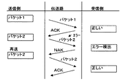
本発明で用いる、Stop and Wait ARQ方式はひとつのパケットを送るごとに相手側からの確認を待つ方式である。伝送路でエラーが発生した毎に、受信側装置は送信側装置へNAK信号を送る。 The Stop and Wait ARQ method used in the present invention is a method of waiting for confirmation from the other party each time one packet is sent. Each time an error occurs in the transmission path, the receiving side device sends a NAK signal to the transmitting side device.
Selectiv Repeat ARQ方式はいくつかのパケットを確認なく送信側装置から受信側装置へ先送りする方式であって、各パケットには番号がついており、送信側装置は受信側装置からのNAK信号に従い、エラーになったパケットのだけを再送する方式である。 The Selective Repeat ARQ method is a method in which several packets are forwarded from the transmission side device to the reception side device without confirmation. Each packet is numbered, and the transmission side device has an error according to the NAK signal from the reception side device. This is a method of retransmitting only the packets that become.
またフレーム構造、データ構造、パケット構造等は通信システムの用途に応じて各種構造が存在することは当業者においては自明である。 It is obvious to those skilled in the art that various structures such as a frame structure, a data structure, a packet structure, and the like exist depending on the use of the communication system.
本発明の最良の実施形態について図1を用いて説明する。 The best embodiment of the present invention will be described with reference to FIG.
図1は第1実施形態における送信側(基地局)1での信号の流れと信号の送受を示す機能ブロック図である。 FIG. 1 is a functional block diagram showing signal flow and signal transmission / reception on the transmission side (base station) 1 in the first embodiment.
簡単のために、基地局の送信系のみを示す。基地局は送信データ2、送信バッファ3、
送信機4、送信制御手段8、エラーレート推定装置10からなる。更に、前記エラーレート推定装置10は再送データ数カウント手段5と送信データ数カウント手段6とエラーレート演算手段7からなる。
For simplicity, only the transmission system of the base station is shown. The base station has
It comprises a
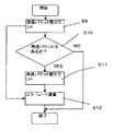
図2のフローチャートによると送信データ数カウントステップS1の後、ステップS2で再送データ数の有無を判定し、ステップS3で再送データ数をカウントし、ステップS4でエラーレートを演算する。以上により基地局側で受信側(移動局)のエラーレートを推定することができる。 According to the flowchart of FIG. 2, after the transmission data number counting step S1, the presence / absence of the number of retransmission data is determined at step S2, the number of retransmission data is counted at step S3, and the error rate is calculated at step S4. As described above, the error rate on the receiving side (mobile station) can be estimated on the base station side.
図3は第2実施形態における送信側(基地局)1での信号の流れと信号の送受を示す機能ブロック図である。 FIG. 3 is a functional block diagram showing signal flow and signal transmission / reception on the transmission side (base station) 1 in the second embodiment.
簡単のために、基地局の送信系のみを示す。基地局は送信データ2、送信バッファ3、
送信機4、送信制御手段8、エラーレート推定装置10からなる。更に、前記エラーレート推定装置10は再送フレーム数カウント手段11と送信フレーム数カウント手段12とエラーレート演算手段7からなる。
For simplicity, only the transmission system of the base station is shown. The base station has
It comprises a
図4のフローチャートによると送信フレーム数カウントステップS5の後、ステップS6で再送フレーム数の有無を判定し、ステップS7で再送フレーム数をカウントし、ステップS8でエラーレートを演算する。以上により基地局側で受信側(移動局)のエラーレートを推定することができる。 According to the flowchart of FIG. 4, after the transmission frame number counting step S5, the presence or absence of the number of retransmission frames is determined at step S6, the number of retransmission frames is counted at step S7, and the error rate is calculated at step S8. As described above, the error rate on the receiving side (mobile station) can be estimated on the base station side.
図5は第3実施形態における送信側(基地局)1での信号の流れと信号の送受を示す機能ブロック図である。 FIG. 5 is a functional block diagram showing signal flow and signal transmission / reception on the transmission side (base station) 1 in the third embodiment.
簡単のために、基地局の送信系のみを示す。基地局は送信データ2、送信バッファ3、
送信機4、送信制御手段8、エラーレート推定装置10からなる。更に、前記エラーレート推定装置10は再送パケット数カウント手段14と送信パケット数カウント手段15とエラーレート演算手段7からなる。
For simplicity, only the transmission system of the base station is shown. The base station has
It comprises a
図6のフローチャートによると送信パケット数カウントステップS9の後、ステップS10で再送パケット数の有無を判定し、ステップS11で再送パケット数をカウントし、ステップS12でエラーレートを演算する。以上により基地局側で受信側(移動局)のエラーレートを推定することができる。 According to the flowchart of FIG. 6, after the transmission packet number counting step S9, the presence / absence of the number of retransmission packets is determined in step S10, the number of retransmission packets is counted in step S11, and the error rate is calculated in step S12. As described above, the error rate on the receiving side (mobile station) can be estimated on the base station side.
次に、図7から図9と図10から図12を用いて、実際のエラーレートの変化を計算例を用いながら説明する。本説明は、Stop and Wait ARQ(自動再送制御)方式による方法であって、図7と図10、図8と図11、図9と図12は対応している。 Next, an actual error rate change will be described using calculation examples with reference to FIGS. 7 to 9 and FIGS. 10 to 12. FIG. This description is based on the Stop and Wait ARQ (automatic retransmission control) method, and FIGS. 7 and 10, FIGS. 8 and 11, and FIGS. 9 and 12 correspond to each other.
最初に図7は送信側から受信側へデータを送り、データ1は正しく送られ、データ2はエラーが検出され、受信側で訂正できなかったためデータ2が再送される様子を示す。
First, FIG. 7 shows a state in which data is sent from the transmitting side to the receiving side,
伝送路は有線伝送路、無線伝送路、有線と無線の伝送路を融合したもののいずれかを、通信システムに応じて用いる。 As the transmission path, any one of a wired transmission path, a wireless transmission path, and a combination of a wired transmission path and a wireless transmission path is used according to the communication system.
第1実施形態について、そのときのデータ数は図10に示され、A,B,Cの3つの条件で計算したものである。条件AのBER(ビットエラーレート)である。データ数の単位はビットである。条件Aは情報部の長さが固定の場合である。
Regarding the first embodiment, the number of data at that time is shown in FIG. 10 and is calculated under three conditions of A, B, and C. BER (bit error rate) of condition A. The unit of the number of data is bits. Condition A is when the length of the information part is fixed.
条件B、条件Cは通常用いられないが、図12のパケット通信との対比で記載した。 Conditions B and C are not normally used, but are described in comparison with the packet communication in FIG.
図10の条件Aはデータ1が100ビット、データ2が100ビット、データ2の再送が100ビット、データ3が100ビットである。このとき送信データの総数が400ビットで再送データ数が100ビットとなり、BER=(100/400)×100=25%となる。
In condition A in FIG. 10,
図10の条件Bはデータ1が100ビット、データ2が50ビット、データ2の再送が50ビット、データ3が100ビットである。このとき送信データの総数が300ビットで再送データ数が50ビットとなり、BER=(50/300)×100=16.7%となる。
In condition B in FIG. 10,
図10の条件Cはデータ1が100ビット、パケット2が50ビット、パケット2の再送が50ビット、パケット3が50ビットである。このとき送信データの総数が250ビットで再送データ数が50ビットとなり、BER=(50/250)×100=20%となる。
In condition C of FIG. 10,
次に、第2実施形態について説明する。図8は送信側から受信側へフレームを送り、フレーム1は正しく送られ、フレーム2はエラーが検出され、受信側で訂正できなかったためフレーム2が再送される様子を示す。
Next, a second embodiment will be described. FIG. 8 shows a state in which a frame is sent from the transmission side to the reception side,
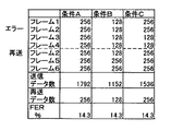
そのときのデータ数は図11に示され、A,B,Cの3つの条件で計算したものである。条件AのFER(フレームエラーレート)である。データ数の単位はビットである。条件Aは情報部の長さが固定の場合である。条件B、条件Cは通常用いられないが、図12のパケットとの対比のため記載した。 The number of data at that time is shown in FIG. 11 and is calculated under the three conditions of A, B, and C. FER (frame error rate) of condition A. The unit of the number of data is bits. Condition A is when the length of the information part is fixed. Conditions B and C are not usually used, but are described for comparison with the packet of FIG.
図11の条件Aはフレーム1が256ビット、フレーム2が256ビット、フレーム2の再送が256ビット、フレーム3が256ビットである。このとき送信データの総数が1024ビットで再送データ数が256ビットとなる。FER=(1/4)×100=25%となる。
In condition A of FIG. 11,
図11の条件Bはフレーム1が256ビット、フレーム2が128ビット、フレーム2の再送が128ビット、フレーム3が256ビットである。このとき送信データの総数が768ビットで再送データ数が128ビットとなる。FER=(1/4)×100=25%となる。
In condition B in FIG. 11,
図11条件Cはフレーム1が256ビット、フレーム2が128ビット、フレーム2の再送が128ビット、フレーム3が128ビットである。このとき送信データの総数が640ビットで再送データ数が128ビットとなる。FER=(1/4)×100=25%となる。
In condition C of FIG. 11,
次に、第3実施形態について説明する。図9は送信側から受信側へパケットを送り、パケット1は正しく送られ、パケット2はエラーが検出され、受信側で訂正できなかったためパケット2が再送される様子を示す。
Next, a third embodiment will be described. FIG. 9 shows a state in which a packet is sent from the transmission side to the reception side,
そのときのデータ数は図12に示され、A,B,Cの3つの条件で計算したものである。条件AのPER(パケットエラーレート)である。データ数の単位はビットである。条件Aは情報部の長さが固定の場合である。 The number of data at that time is shown in FIG. 12, and is calculated under the three conditions of A, B, and C. This is the PER (packet error rate) of condition A. The unit of the number of data is bits. Condition A is when the length of the information part is fixed.
図12の条件Aはパケット1が64ビット、パケット2が64ビット、パケット2の再送が64ビット、パケット3が64ビットである。このとき送信データの総数が256ビットで再送データ数が64ビットとなる。PER=(1/4)×100=25%となる。
Condition A in FIG. 12 is that
図12の条件Bはパケット1が64ビット、パケット2が32ビット、パケット2の再送が32ビット、パケット3が64ビットである。このとき送信データの総数が192ビットで再送データ数が32ビットとなる。PER=(1/4)×100=25%となる。
In condition B of FIG. 12,
図12の条件Cはパケット1が64ビット、パケット2が32ビット、パケット2の再送が32ビット、パケット3が32ビットである。このとき送信データの総数が160ビットで再送データ数が32ビットとなり、PER=(1/4)×100=25%となる。
Condition C in FIG. 12 is that
データ数をもとに計算した場合は、エラーレートが25%、16.7%、20%と変化するが、フレーム数やパケット数をもとに計算すると、送信データ数と再送データ数が異なっても、エラーレートとしては全て同じ(本計算例では25%)になる場合もある。 When calculated based on the number of data, the error rate changes to 25%, 16.7%, and 20%, but when calculated based on the number of frames and packets, the number of transmitted data and the number of retransmitted data differ. However, the error rates may all be the same (25% in this calculation example).
次に、図13から図18を用いて、実際のエラーレートの変化を計算例を用いながら説明する。本説明は、Selectiv Repeat ARQ(自動再送制御)方式による方法であって、図13と図14、図15と図16、図17と図18は対応している。 Next, an actual error rate change will be described with reference to FIGS. 13 to 18 using calculation examples. This description is based on the method of Selective Repeat ARQ (automatic retransmission control), and FIGS. 13 and 14, FIGS. 15 and 16, and FIGS. 17 and 18 correspond to each other.
まず、第4実施形態について図13と図14を用いて説明する。 First, a fourth embodiment will be described with reference to FIGS. 13 and 14.
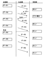
送信側から受信側へデータを連続して、最初4組(図13の点線まで)をまとめて送信し、伝送路でデータ2に誤り訂正できないエラーが生じ、受信側からNAKを送信し、データ2だけを再送要求している。点線以降にデータ2を再送し、引き続きデータ5とデータ6を送信した例である。
Data is continuously transmitted from the transmission side to the reception side, and the first four sets (up to the dotted line in FIG. 13) are transmitted together. An error that cannot be corrected in
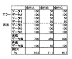
図14はビットエラーレートについてA,B,Cの3つの条件で計算したものである。条件Aは最初の4組のデータが全て、100ビットの例である。データ2で100ビットエラーを生じたためBER=(100/700)×100=14.3%となる。
FIG. 14 shows the bit error rate calculated under the three conditions A, B, and C. Condition A is an example in which the first four sets of data are all 100 bits. Since a 100-bit error has occurred in
条件Bはでは最初の4組のデータが全て、50ビットで、データ2で50ビットのエラーを生じ、50ビットを再送し、データ5とデータ6でそれぞれ100ビットを送信した例である。BER=(50/450)×100=11.1%となる。
Condition B is an example in which the first four sets of data are all 50 bits,
条件Cはデータ1とデータ2で100ビットづつ、データ3とデータ4で50ビットづつ送信したものである。伝送路でのエラーはデータ2において50ビットである。
Condition C is that
BER=(100/600)×100=16.7%となる。 BER = (100/600) × 100 = 16.7%.
第5実施形態について図15と図16を用いて説明する。送信側から受信側へフレームを連続して、最初4組(図15の点線まで)をまとめて送信し、伝送路でフレーム2に誤り訂正できないエラーが生じ、受信側からNAKを送信し、フレーム2だけを再送要求している。点線以降にフレーム2を再送し、引き続きフレーム5とフレーム6を送信した例である。
A fifth embodiment will be described with reference to FIGS. 15 and 16. Frames are continuously transmitted from the transmission side to the reception side, and the first four sets (up to the dotted line in FIG. 15) are transmitted together. An error that cannot be corrected in
図16はフレームエラーレートについてA,B,Cの3つの条件で計算したものである。条件Aは最初の4組のフレームが全て、256ビットの例である。フレーム2で256ビットエラーを生じたためFER=(1/7)×100=14.3%となる。
FIG. 16 shows the frame error rate calculated under the three conditions A, B, and C. Condition A is an example in which the first four sets of frames are all 256 bits. Since a 256-bit error has occurred in
条件Bはでは最初の4組のフレームが全て、128ビットで、フレーム2で128ビットのエラーを生じ、128ビットを再送し、フレーム5とフレーム6でそれぞれ256ビットを送信した例である。FER=(1/7)×100=14.3%となる。
Condition B is an example in which the first four sets of frames are all 128 bits, a 128-bit error occurs in
条件Cはフレーム1とフレーム2で256ビットづつ、フレーム3とフレーム4で128ビットづつ送信したものである。伝送路でのエラーはフレーム2において256ビットである。FER=(1/7)×100=14.3%となる。
Condition C is that
第6実施形態について図17と図18を用いて説明する。送信側から受信側へパケットを連続して、最初4組(図17の点線まで)をまとめて送信し、伝送路でパケット2に誤り訂正できないエラーが生じ、受信側からNAKを送信し、パケット2だけを再送要求している。点線以降にパケット2を再送し、引き続きパケット5とパケット6を送信した例である。
A sixth embodiment will be described with reference to FIGS. 17 and 18. Packets are continuously transmitted from the transmission side to the reception side, and the first four sets (up to the dotted line in FIG. 17) are transmitted collectively. An error that cannot be corrected in the
図18はパケットエラーレートについてA,B,Cの3つの条件で計算したものである。条件Aは最初の4組のパケットが全て、64ビットの例である。パケット2で64ビットエラーを生じたためPER=(1/7)×100=14.3%となる。
FIG. 18 shows the packet error rate calculated under the three conditions A, B, and C. Condition A is an example in which the first four sets of packets are all 64 bits. Since a 64-bit error has occurred in
条件Bはでは最初の4組のパケットが全て、32ビットで、パケット2で32ビットのエラーを生じ、32ビットを再送し、パケット5とパケット6でそれぞれ64ビットを送信した例である。PER=(1/7)×100=14.3%となる。
Condition B is an example in which the first four sets of packets are all 32 bits, a 32-bit error occurs in
条件Cはパケット1とパケット2で64ビットづつ、パケット3とパケット4で32ビットづつ送信したものである。伝送路でのエラーはパケット2において64ビットである。
Condition C is that
PER=(1/7)×100=14.3%となる。 PER = (1/7) × 100 = 14.3%.
第7実施形態を次に説明する。図20は図1のエラーレート推定装置にサンプリング手段18とエラーレート推定値の変化率演算手段17とを付加したものである。前記変化率演算手段17により、エラーレートの変化を予測することが可能となり、送信側(基地局)1から受信側(移動局)への適切な送信パラメータ(データレート・変調方式・情報長、送信電力等)を選択することが可能となる。
Next, a seventh embodiment will be described. FIG. 20 is obtained by adding a sampling means 18 and an error rate estimated value change rate calculating means 17 to the error rate estimating apparatus of FIG. The change rate calculating means 17 makes it possible to predict a change in error rate, and appropriate transmission parameters (data rate, modulation method, information length, transmission from the transmission side (base station) 1 to the reception side (mobile station), Transmission power etc.) can be selected.
以下、エラーレート推定装置における演算について説明する。時刻T1でのエラーレート推定値をE1、時刻T2でのエラーレート推定値をE2とすると時刻Tでのエラーレート推定値Eは次式で表すことができる。2点を通る直線の方程式はE=((E2−E1)/(T2−T1))T+(E1T2−E2T1)となる。(T1、E1)、(T2、E2)の組み合わせを次々に推定すれば、(T、E)の組み合わせも次々に計算することができる。実際のT2−T1の値は0.5秒から5秒程度が適当である。 Hereinafter, the calculation in the error rate estimation apparatus will be described. When the estimated error rate at time T1 is E1, and the estimated error rate at time T2 is E2, the estimated error rate E at time T can be expressed by the following equation. The equation of the straight line passing through the two points is E = ((E2-E1) / (T2-T1)) T + (E1T2-E2T1). If the combinations of (T1, E1) and (T2, E2) are estimated one after another, the combinations of (T, E) can also be calculated one after another. The actual value of T2-T1 is suitably about 0.5 to 5 seconds.
パケットによるデータ伝送はデータの到達が不連続であるため、受信側(移動局)のおかれている移動環境・電波環境を送信側(基地局)で迅速に把握することが困難であるので前記変化率演算手段17を基地局1に具備することでより有効な基地局1となる。
Since data transmission by packet is discontinuous, it is difficult for the transmitting side (base station) to quickly grasp the mobile environment / radio wave environment where the receiving side (mobile station) is located. By providing the change rate calculation means 17 in the
図21は処理の流れを示すフローチャートである。図21のフローチャートによると送信データ数カウントステップS13の後、ステップS14で再送データ数の有無を判定し、ステップS15で再送データ数をカウントし、ステップS16でエラーレートを演算する。次にステップ17でエラーレートをサンプリングし、ステップS18でエラーレート変化率演算する。前記エラーレートの変化率の演算により、受信側の電波環境の変化を推定することができ、迅速に再送制御を実施し、スループットを向上させることが可能となる。
FIG. 21 is a flowchart showing the flow of processing. According to the flowchart of FIG. 21, after the transmission data number counting step S13, the presence or absence of the number of retransmission data is determined at step S14, the number of retransmission data is counted at step S15, and the error rate is calculated at step S16. Next, the error rate is sampled in
本発明は、主に無線データ通信システムにおける説明をしたが、有線データ通信システム、光データ通信システム等にも適用可能である。 Although the present invention has been mainly described in the wireless data communication system, it can also be applied to a wired data communication system, an optical data communication system, and the like.
1:送信側装置(基地局装置)
2:送信データ
3:送信バッファ
4:送信機
5:再送データ数カウント手段
6:送信データ数カウント手段
7:エラーレート演算手段
8:送信制御手段
9:アンテナ
10、13、16、18:エラーレート推定装置
11:送信データ数カウント手段
12:再送データ数カウント手段
13:送信データ数カウント手段
17:エラーレート変化率演算手段
18:エラーレートサンプリング手段
30、34:アドレス部
31、35:制御部
32、36:情報部
33、37、43、45:FCS(フレームチェックシーケンス)
44:情報部
50:デジタル復調器
51:位相点分布検出回路
52:推定回路
1: Transmission side device (base station device)
2: Transmission data 3: Transmission buffer 4: Transmitter 5: Retransmission data number counting means 6: Transmission data number counting means 7: Error rate calculation means 8: Transmission control means 9:
44: Information section 50: Digital demodulator 51: Phase point distribution detection circuit 52: Estimation circuit
Claims (6)
2. The error rate estimation apparatus according to claim 1, further comprising an error rate sampling unit and an error rate change rate calculation unit.
Priority Applications (1)
| Application Number | Priority Date | Filing Date | Title |
|---|---|---|---|
| JP2006019480A JP2007201927A (en) | 2006-01-27 | 2006-01-27 | Error rate estimation device |
Applications Claiming Priority (1)
| Application Number | Priority Date | Filing Date | Title |
|---|---|---|---|
| JP2006019480A JP2007201927A (en) | 2006-01-27 | 2006-01-27 | Error rate estimation device |
Publications (1)
| Publication Number | Publication Date |
|---|---|
| JP2007201927A true JP2007201927A (en) | 2007-08-09 |
Family
ID=38456043
Family Applications (1)
| Application Number | Title | Priority Date | Filing Date |
|---|---|---|---|
| JP2006019480A Pending JP2007201927A (en) | 2006-01-27 | 2006-01-27 | Error rate estimation device |
Country Status (1)
| Country | Link |
|---|---|
| JP (1) | JP2007201927A (en) |
Cited By (2)
| Publication number | Priority date | Publication date | Assignee | Title |
|---|---|---|---|---|
| JP2010016813A (en) * | 2008-06-23 | 2010-01-21 | Hitachi Ltd | Physical layer transmission rate control system of priority control type in video transmission on radio network |
| CN117271202A (en) * | 2023-11-23 | 2023-12-22 | 中国西安卫星测控中心 | Optimal extraction method for multi-pass retransmission data |
-
2006
- 2006-01-27 JP JP2006019480A patent/JP2007201927A/en active Pending
Cited By (3)
| Publication number | Priority date | Publication date | Assignee | Title |
|---|---|---|---|---|
| JP2010016813A (en) * | 2008-06-23 | 2010-01-21 | Hitachi Ltd | Physical layer transmission rate control system of priority control type in video transmission on radio network |
| CN117271202A (en) * | 2023-11-23 | 2023-12-22 | 中国西安卫星测控中心 | Optimal extraction method for multi-pass retransmission data |
| CN117271202B (en) * | 2023-11-23 | 2024-02-09 | 中国西安卫星测控中心 | Optimal extraction method for multi-pass retransmission data |
Similar Documents
| Publication | Publication Date | Title |
|---|---|---|
| US6907005B1 (en) | Flexible ARQ for packet data transmission | |
| US7236740B2 (en) | Data retransmission apparatus and method in a mobile communication system employing HARQ technique | |
| US8402343B2 (en) | Reliable packet cut-through | |
| US8687548B2 (en) | Method and arrangement in a telecommunication system for handling status information of data units | |
| TWI471024B (en) | Method and apparatur of exchanging data between a base station and a mobile station | |
| US8953484B2 (en) | Communication device and communication method | |
| RU2456751C2 (en) | Method of repeated data transfer and wireless communication device | |
| JP2006060408A (en) | Radio packet communication method and radio station | |
| JP2007181127A (en) | Communication device, communication method, and program | |
| JP2008103862A (en) | Mobile communication system, base station device, and uplink packet resending frequency estimating method used for them | |
| JP3844957B2 (en) | Retransmission control method and apparatus | |
| JP5460743B2 (en) | Wireless equipment | |
| US8811500B2 (en) | Data transmission | |
| JP2009506599A (en) | Data unit transmission method | |
| US20090262646A1 (en) | Transport protocol for efficient aggregation of heterogeneous losssy paths | |
| JP2000349742A (en) | Communication terminal equipment, base station device and radio communication method | |
| JP5695506B2 (en) | Data transmission device | |
| WO2010041295A1 (en) | Radio relay device and reproduction method in relay station | |
| JP2007201927A (en) | Error rate estimation device | |
| JP4772533B2 (en) | Data retransmission control method, system, and data retransmission control device | |
| JP2005236923A (en) | Radio packet communication method and radio station | |
| JP2009081567A (en) | Retransmission control system, retransmission control method, transmitter and receiver | |
| JP6011813B2 (en) | COMMUNICATION DEVICE AND ITS COMMUNICATION CONTROL METHOD | |
| JPWO2014155495A1 (en) | Communication device and transmission device | |
| US20110128854A1 (en) | Medium access control forwarding protocol |