JP2007201355A - Electrode for placing wafer - Google Patents
Electrode for placing wafer Download PDFInfo
- Publication number
- JP2007201355A JP2007201355A JP2006020857A JP2006020857A JP2007201355A JP 2007201355 A JP2007201355 A JP 2007201355A JP 2006020857 A JP2006020857 A JP 2006020857A JP 2006020857 A JP2006020857 A JP 2006020857A JP 2007201355 A JP2007201355 A JP 2007201355A
- Authority
- JP
- Japan
- Prior art keywords
- wafer
- electrode
- heat transfer
- dielectric
- transfer gas
- Prior art date
- Legal status (The legal status is an assumption and is not a legal conclusion. Google has not performed a legal analysis and makes no representation as to the accuracy of the status listed.)
- Granted
Links
Images


Abstract
Description
本発明は、プラズマ処理装置にかかわり、特に半導体基板等の被処理基板を、プラズマを用いてエッチング処理を行うのに好適なプラズマ処理装置のウエハ載置用電極に関するものである。 The present invention relates to a plasma processing apparatus, and more particularly to a wafer mounting electrode of a plasma processing apparatus suitable for etching a target substrate such as a semiconductor substrate using plasma.
半導体製造プロセスでは、一般にプラズマを用いたドライエッチングが行われている。ドライエッチングを行うためのプラズマ処理装置は種々の方式の装置が使用されている。 In the semiconductor manufacturing process, dry etching using plasma is generally performed. Various types of plasma processing apparatuses for performing dry etching are used.
プラズマ処理装置は、一般に真空容器と、これに接続されたガス供給系、処理室内圧力を所定の値に保持する排気系、基板を搭載する電極、真空容器内にプラズマを発生させるためのアンテナなどから構成されている。前記アンテナに高周波電力が供給されることによりシャワープレートから処理室内に供給された処理ガスが解離してプラズマが発生し、さらにウエハ載置用電極上に設置された基板のエッチングが進行する。 A plasma processing apparatus generally includes a vacuum vessel, a gas supply system connected to the vacuum vessel, an exhaust system for maintaining the pressure in the processing chamber at a predetermined value, an electrode for mounting a substrate, an antenna for generating plasma in the vacuum vessel, etc. It is composed of When high frequency power is supplied to the antenna, the processing gas supplied from the shower plate into the processing chamber is dissociated to generate plasma, and etching of the substrate placed on the wafer mounting electrode proceeds.
所望のエッチング性能を確保するためには、プラズマの分布や組成、密度など多数のパラメータの制御が必要であるが、その中のひとつとしてウエハ温度制御がある。 In order to ensure the desired etching performance, it is necessary to control a number of parameters such as plasma distribution, composition and density, and one of them is wafer temperature control.
所望のウエハ温度にする方法として、ウエハと溶射膜(誘電体)の間に溝を設け、そこに伝熱用ガスを供給する方法がある(例えば、特許文献1参照)。しかし、これだけでは所望のウエハ温度分布にすることは不可能である。 As a method for obtaining a desired wafer temperature, there is a method in which a groove is provided between a wafer and a sprayed film (dielectric), and a heat transfer gas is supplied to the groove (for example, see Patent Document 1). However, it is impossible to achieve a desired wafer temperature distribution by this alone.
そこで、場所によってウエハと溶射膜間の圧力を変化させることで、ウエハと溶射膜間の熱通過率を変化させ、所望のウエハ温度分布にすることが提案されている(例えば、特許文献2参照)。
実際にプラズマを用いて誘電体(電極)に静電吸着したウエハの加工をする場合は、静電吸着の原理から、ウエハと誘電体間には高電圧がかかっていることに注意する必要がある。すなわち、パッシェンの法則からウエハと誘電体間で放電が発生する可能性がある。特に誘電体表面に伝熱ガス用の溝を設けている場合、同じ圧力でもウエハと誘電体の吸着部よりも溝部でより放電が起こりやすい。 When processing a wafer that is actually electrostatically attracted to a dielectric (electrode) using plasma, it is necessary to be aware that a high voltage is applied between the wafer and the dielectric due to the principle of electrostatic attraction. is there. In other words, discharge may occur between the wafer and the dielectric due to Paschen's law. In particular, when a groove for heat transfer gas is provided on the dielectric surface, discharge is more likely to occur in the groove portion than in the wafer and dielectric adsorption portion even at the same pressure.
本発明は、ウエハと誘電体間で放電が発生しない、かつ所望のウエハ温度分布を実現できる電極を提供することを目的とする。 An object of the present invention is to provide an electrode that does not generate a discharge between a wafer and a dielectric and can realize a desired wafer temperature distribution.
上記目的を達成するために、本発明は、誘電体に溝を設けることなく、ウエハと誘電体間の熱伝達率に分布を与える。分布を与える方法として、誘電体上の位置によって誘電体の表面粗さを変化させる。 In order to achieve the above object, the present invention provides a distribution of the heat transfer coefficient between the wafer and the dielectric without providing grooves in the dielectric. As a method of giving the distribution, the surface roughness of the dielectric is changed depending on the position on the dielectric.
このウエハ載置用電極は、表面粗さによってウエハと誘電体間の熱伝達率が変化するため、冷却ガス用の溝を設けることなく所望のウエハ温度分布を実現できる。 Since the heat transfer coefficient between the wafer and the dielectric varies depending on the surface roughness, the wafer mounting electrode can realize a desired wafer temperature distribution without providing a cooling gas groove.
以上説明した本発明によれば、ウエハと電極間で発生する放電がなくなるため、電極表面劣化による電極交換などの作業が不要になり、スループットが向上する。また、ウエハと誘電体間の圧力の場所によって変化可能なので、所望のウエハ温度分布にすることができる。 According to the present invention described above, since the discharge generated between the wafer and the electrode is eliminated, work such as electrode replacement due to electrode surface deterioration becomes unnecessary, and throughput is improved. Further, since the pressure can be changed depending on the location of the pressure between the wafer and the dielectric, a desired wafer temperature distribution can be obtained.
本発明にかかるウエハ載置用電極の第1の実施例を、図1のウエハ載置用電極の概略図を用いて説明する。本実施例にかかるウエハ載置用電極は、電極の構造体となる基材1、基材1の表面に環状(円形)に形成された複数の誘電体のアルミナ溶射膜(以下、溶射膜ということがある)2〜6、伝熱ガス用噴出孔7、電極温調用冷媒が流れる冷媒溝9、伝熱ガスを供給する伝熱ガス用パイプ10などから構成され、アルミナ溶射膜の上にウエハ8が載置される。アルミナ溶射膜は、中心に円形の溶射膜6が配置され、その外側に順次環状の溶射膜5,4,3,2が互いに接して配置される。伝熱ガス用噴出孔7からな同一の伝熱ガス用パイプ10を介して同一の条件の伝熱ガスが供給される。なお、図には明示していないが、本ウエハ載置用電極は、プラズマエッチング処理装置内に設置されている。
A first embodiment of the wafer mounting electrode according to the present invention will be described with reference to the schematic diagram of the wafer mounting electrode of FIG. The electrode for mounting a wafer according to this example includes a
プラズマエッチング処理室内に搬送されたウエハ8を溶射膜2〜6の上に設置し、処理室内圧力を所定の圧力にしたのち、処理室内にプラズマを発生させる。図には明示していないウエハバイアス供給部からウエハにバイアスを印加して、ウエハを溶射膜2〜6に吸着させる。その後、伝熱用ガスを伝熱ガス用噴出孔7からウエハ8と溶射膜2〜6の間に供給する。図には明示していない圧力計とガス流量計で、ウエハ8と溶射膜2〜6の間の圧力を制御する。なお、冷媒溝9には例えば20℃に設定された冷媒を流して、電極全体を温調している。
The
誘電体を形成する溶射膜は、アルミナ(Al2O3)を主成分とした溶射膜を用いることができ、またイットリア(Y2O3)を主成分とする溶射膜を用いることができる。 As the thermal spray film forming the dielectric, a thermal spray film mainly composed of alumina (Al 2 O 3 ) can be used, and a thermal spray film mainly composed of yttria (Y 2 O 3 ) can be used.
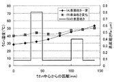
図2に放電中のウエハ表面の温度分布を示す。図2の網がけで示される曲線(A)は溶射膜2〜6の表面粗さRaが同一でRa=0.8μmの場合であり、図2の細い実線で示される曲線(B)は溶射膜2〜6の表面粗さRaがそれぞれ異なっている場合のウエハ温度である。曲線(B)の溶射膜2〜6の表面粗さRaは図2に太い実線で示す通りである。すなわち、この実施例では、溶射膜2はRa=0.08μm、溶射膜3はRa=0.4μm、溶射膜4はRa=0.08μm、溶射膜5はRa=0.08μm、溶射膜6はRa=0.08μmとされている。なお、ウエハバイアスは1000Wであり、ウエハと溶射膜間には伝熱ガスとしてHeガスを供給し、その圧力は1.5kPaである。またUHFタイプのプラズマ装置を使い、Arガスでプラズマ放電を発生させた。
FIG. 2 shows the temperature distribution on the wafer surface during discharge. A curved line (A) shown by shading in FIG. 2 is the case where the surface roughness Ra of the sprayed
溶射膜2〜6の表面粗さが同一の場合は、曲線(A)に示すように、ウエハ温度分布は中心部が低く外周部が高くなることがわかる。すなわち、中心部の28℃から外周部の54℃まで急激にかつ広範囲上昇している。にこれは、ウエハと溶射膜間の接触熱通過率が、電極上の位置に依らず一定であることが原因である。
When the surface roughness of the sprayed
他方、溶射膜2〜6の表面粗さを変化させた場合の温度分布は、曲線(B)に示すように、ウエハ中心部温度が低く外周部温度が高いという傾向は同じであるが、面内温度差は小さくなっていることが分かる。すなわち、中心部の40℃から外周部の50℃に緩やかに上昇している。
On the other hand, the temperature distribution when the surface roughness of the sprayed
これは、図3に示すように、ウエハと溶射膜間の接触熱通過率が、溶射膜の表面粗さRaによって異なることに起因する。すなわち、表面粗さRa=0.8μmでは接触熱通過率はおよそ80W/m2Kであるのに対し、表面粗さRa=0.4μmでは接触熱通過率はおよそ200W/m2Kであり、表面粗さRa=0.2μmでは接触熱通過率はおよそ400W/m2Kであり、表面粗さRa=0.08μmでは接触熱通過率はおよそ500W/m2Kである。すなわち、ウエハ温度分布については、溶射膜にウエハと溶射膜が接触する領域と、接触しない領域を設けることと同様の効果を得ることができる。 This is because, as shown in FIG. 3, the contact heat passage rate between the wafer and the sprayed film varies depending on the surface roughness Ra of the sprayed film. That is, when the surface roughness Ra = 0.8 μm, the contact heat transfer rate is approximately 80 W / m 2 K, whereas when the surface roughness Ra = 0.4 μm, the contact heat transfer rate is approximately 200 W / m 2 K. When the surface roughness Ra = 0.2 μm, the contact heat passage rate is about 400 W / m 2 K, and when the surface roughness Ra = 0.08 μm, the contact heat passage rate is about 500 W / m 2 K. That is, with respect to the wafer temperature distribution, it is possible to obtain the same effect as providing a region where the wafer and the sprayed film are in contact with each other and a region where they are not in contact with each other.
さらに、ウエハと溶射膜は接触しているため、パッシェンの法則からウエハと溶射膜の間で放電が発生する可能性は非常に低くなる。溶射膜表面で発生する放電がなくなるため、溶射膜劣化あるいはウエハと溶射膜間の放電による装置の停止がなくなり、スループットの向上が期待できる。 Furthermore, since the wafer and the sprayed film are in contact with each other, the possibility that a discharge will occur between the wafer and the sprayed film is very low due to Paschen's law. Since there is no discharge generated on the surface of the sprayed film, there is no need to stop the apparatus due to deterioration of the sprayed film or discharge between the wafer and the sprayed film, and an improvement in throughput can be expected.
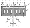
電極の位置によって伝熱ガスの圧力を制御可能とした本発明の第2の実施例を、図4を用いて説明する。第2の実施例のウエハ載置用電極は、電極の構造体となる基材1、誘電体のアルミナ溶射膜2〜6、伝熱ガス用噴出孔20、21、電極温調用冷媒が流れる冷媒溝9、伝熱ガスを供給する伝熱ガス用パイプ22、23などから構成され、ウエハ8が載置される。伝熱ガス用噴出孔20は伝熱ガス用パイプ22に、伝熱ガス用噴出孔21は伝熱ガス用パイプ23にそれぞれ接続されている。伝熱ガス用パイプ22には圧力計24と流量計26が、伝熱ガス用パイプ23には圧力計25と流量計27がそれぞれ接続されている。なお、図には明示していないが、第2の実施例のウエハ載置用電極はプラズマエッチング処理装置内に設置されている。また、冷媒溝には20℃に設定された冷媒を流して、電極全体を温調している。
A second embodiment of the present invention in which the pressure of the heat transfer gas can be controlled by the position of the electrode will be described with reference to FIG. The electrode for wafer mounting of the second embodiment includes a
プラズマエッチング処理室内に搬送されたウエハ8を、溶射膜2〜6の上に設置し、処理室内圧力を所定の圧力にしたのち、処理室内にプラズマを発生させる。図には明示していないウエハバイアス供給部からウエハにバイアスを印加して、ウエハを溶射膜2〜6に吸着させる。その後、伝熱用ガスを伝熱ガス用噴出孔20、21からウエハ8と溶射膜2〜6の間に供給する。ガス噴出孔20、21から供給する伝熱用ガスは、それぞれ圧力計24、25が所定の圧力を示すように流量計26、27で制御している。この実施例でも、溶射膜2〜6の表面粗さは図2に示す通りである。
The
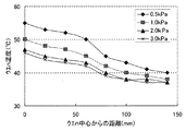
ウエハバイアスを2000Wで一定とし、ウエハ外周部の圧力を示す圧力計25を3.0kPaで一定とし、ウエハ中央部の圧力を示す圧力計24を0.5kPaから3.0kPaまで変化させたときのウエハ温度分布を図5示す。圧力計25を一定圧力に保持し、圧力計24を変化させることで、ウエハ温度分布を制御できることが分かる。
When the wafer bias is constant at 2000 W, the
このように、電極上の位置によってガスの圧力を変化させることにより、ウエハ温度分布を所望の分布にすることができる。すなわち、ウエハから溶射膜に流れる熱量は、ウエハと溶射膜間のガスの圧力によって変化する。ウエハと溶射膜間に存在するガスは、ガス同士の衝突が無視できる分子流であるため、ガスの数が多ければその分だけ熱の移動も多くなる。そのため、ウエハから溶射膜への熱の移動量は、ガスの圧力が低ければ熱の移動量は小さく、ガスの圧力が高ければ熱の移動量も多くなる。つまり、ウエハ温度を高くするためには、ウエハと溶射膜間のガスの圧力を低くすればよく、逆にウエハ温度を低くしたければウエハと溶射膜間のガスの圧力を高くすればよいことになる。これを定量的に表すと、例えば、ガスをHeと仮定した場合、ガスの圧力と熱通過率は、およそ次のようになる。ウエハと溶射膜間のHeガスのガス圧力が、0.5kPaであるときには熱通過率が193W/m2K、1.0kPaであるときには熱通過率が364W/m2K、2.0kPaであるときには熱通過率が650W/m2K、3.0kPaであるときには熱通過率が881W/m2Kとなる。このように、ガスの圧力が高いほうがHeの熱通過率も大きくなるので、その分だけウエハの温度も低くなる。 Thus, by changing the gas pressure depending on the position on the electrode, the wafer temperature distribution can be made a desired distribution. That is, the amount of heat flowing from the wafer to the sprayed film changes depending on the gas pressure between the wafer and the sprayed film. Since the gas existing between the wafer and the sprayed film is a molecular flow in which collision between the gases can be ignored, the more the number of gases, the more heat transfer. Therefore, the amount of heat transferred from the wafer to the sprayed film is small when the gas pressure is low, and the amount of heat transferred is large when the gas pressure is high. In other words, in order to increase the wafer temperature, the gas pressure between the wafer and the sprayed film should be lowered. Conversely, to lower the wafer temperature, the gas pressure between the wafer and the sprayed film should be increased. become. When this is expressed quantitatively, for example, when the gas is assumed to be He, the pressure and heat passage rate of the gas are approximately as follows. When the gas pressure of the He gas between the wafer and the sprayed film is 0.5 kPa, the heat transfer rate is 193 W / m 2 K, and when it is 1.0 kPa, the heat transfer rate is 364 W / m 2 K, 2.0 kPa. Sometimes the heat passage rate is 650 W / m 2 K, and when it is 3.0 kPa, the heat passage rate is 881 W / m 2 K. Thus, the higher the gas pressure, the higher the heat transfer rate of He, so the temperature of the wafer is lowered accordingly.
本発明によれば、ウエハと電極を全面で接触させ、また電極上の位置によって誘電体の表面粗さを変化させることで、ウエハと誘電体の接触熱通過率を変化させることができ、ウエハの温度を制御するとともに、ウエハと誘電体の間に大きな間隙を生じないので放電の発生をなくし、スループットの向上に寄与する。 According to the present invention, the contact heat passing rate between the wafer and the dielectric can be changed by bringing the wafer and the electrode into contact with each other over the entire surface and changing the surface roughness of the dielectric depending on the position on the electrode. In addition to controlling the temperature of the wafer, no large gap is formed between the wafer and the dielectric, so that no discharge is generated and the throughput is improved.
以上の実施例では、ドライエッチング装置を例に説明したが、各種の放電(UHF−ECR方式、容量結合放電、誘導結合放電、マグネトロン放電、表面波励起放電、TCP放電等)を利用したドライエッチング装置において同様の作用効果がある。さらにドライエッチング装置ばかりでなく、その他のプラズマ処理装置、例えばプラズマCVD装置、アッシング装置、表面改質装置においても同様の作用効果がある。 In the above embodiments, the dry etching apparatus has been described as an example, but dry etching using various discharges (UHF-ECR method, capacitively coupled discharge, inductively coupled discharge, magnetron discharge, surface wave excitation discharge, TCP discharge, etc.). There are similar effects in the apparatus. Further, not only the dry etching apparatus but also other plasma processing apparatuses such as a plasma CVD apparatus, an ashing apparatus, and a surface modification apparatus have the same effects.
1 基材
2〜6 溶射膜
7 伝熱ガス用噴出孔
8 ウエハ
9 冷媒溝
10 伝熱ガス用パイプ
20、21 伝熱ガス用噴出孔
22、23 伝熱ガス用パイプ
24、25 圧力計
26、27 流量計
DESCRIPTION OF
Claims (4)
前記誘電体層の全面がウエハに接触するように配置され、ウエハと誘電体層が接触する領域における前記誘電体の表面粗さを領域の位置によって変えた
ことを特徴とするウエハ載置用電極。 A dielectric layer provided on the surface of the base material, a groove for supplying a wafer temperature adjusting coolant provided in the base material, and a heat transfer gas ejection hole for ejecting heat transfer gas from the surface of the dielectric layer And a heat transfer gas supply pipe for supplying heat transfer gas to the heat transfer gas ejection holes, and a wafer is set on the dielectric layer, and the wafer is fixed by electrostatic attraction. Wafer mounting for mounting a wafer used in a plasma processing apparatus that flows a temperature adjusting refrigerant and supplies a heat transfer gas between the dielectric layer and the wafer to adjust the wafer temperature while processing the wafer. In the mounting electrode,
A wafer mounting electrode, wherein the dielectric layer is disposed so that the entire surface of the dielectric layer is in contact with the wafer, and the surface roughness of the dielectric in the region where the wafer and the dielectric layer are in contact is changed depending on the position of the region. .
前記ウエハと前記誘電体間に供給する伝熱用ガスの圧力を、電極上の位置によって異なる圧力で制御する
ことを特徴とするウエハ載置用電極。 The wafer mounting electrode according to claim 1,
A wafer mounting electrode, wherein a pressure of a heat transfer gas supplied between the wafer and the dielectric is controlled by a pressure which varies depending on a position on the electrode.
前記誘電体層がアルミナ(Al2O3)を主成分とした誘電体である
ことを特徴とするウエハ載置用電極。 The electrode for mounting a wafer according to claim 1 or 2,
The electrode for wafer mounting, wherein the dielectric layer is a dielectric mainly composed of alumina (Al 2 O 3 ).
前記誘電体層がイットリア(Y2O3)を主成分とした誘電体であることを特徴とするウエハ載置用電極。 The electrode for mounting a wafer according to claim 1 or 2,
The electrode for wafer mounting, wherein the dielectric layer is a dielectric composed mainly of yttria (Y 2 O 3 ).
Priority Applications (1)
| Application Number | Priority Date | Filing Date | Title |
|---|---|---|---|
| JP2006020857A JP4611217B2 (en) | 2006-01-30 | 2006-01-30 | Wafer mounting electrode |
Applications Claiming Priority (1)
| Application Number | Priority Date | Filing Date | Title |
|---|---|---|---|
| JP2006020857A JP4611217B2 (en) | 2006-01-30 | 2006-01-30 | Wafer mounting electrode |
Publications (2)
| Publication Number | Publication Date |
|---|---|
| JP2007201355A true JP2007201355A (en) | 2007-08-09 |
| JP4611217B2 JP4611217B2 (en) | 2011-01-12 |
Family
ID=38455602
Family Applications (1)
| Application Number | Title | Priority Date | Filing Date |
|---|---|---|---|
| JP2006020857A Expired - Fee Related JP4611217B2 (en) | 2006-01-30 | 2006-01-30 | Wafer mounting electrode |
Country Status (1)
| Country | Link |
|---|---|
| JP (1) | JP4611217B2 (en) |
Cited By (5)
| Publication number | Priority date | Publication date | Assignee | Title |
|---|---|---|---|---|
| JP2009081223A (en) * | 2007-09-26 | 2009-04-16 | Tokyo Electron Ltd | Electrostatic chuck member |
| JP2012129547A (en) * | 2012-02-25 | 2012-07-05 | Tokyo Electron Ltd | Substrate mounting table, substrate processing apparatus, and temperature control method |
| JP2012129549A (en) * | 2012-03-06 | 2012-07-05 | Tokyo Electron Ltd | Electrostatic chuck member |
| JP2016152314A (en) * | 2015-02-17 | 2016-08-22 | パナソニックIpマネジメント株式会社 | Plasma treatment apparatus and manufacturing method of electronic component |
| WO2019239893A1 (en) * | 2018-06-12 | 2019-12-19 | 東京エレクトロン株式会社 | Mounting stage, substrate processing device, and edge ring |
Families Citing this family (1)
| Publication number | Priority date | Publication date | Assignee | Title |
|---|---|---|---|---|
| CN108364845B (en) * | 2018-03-20 | 2020-05-05 | 武汉华星光电技术有限公司 | Dry etching equipment |
Citations (7)
| Publication number | Priority date | Publication date | Assignee | Title |
|---|---|---|---|---|
| JPS60115226A (en) * | 1983-11-28 | 1985-06-21 | Hitachi Ltd | Substrate temperature control method |
| JPH01251735A (en) * | 1988-03-31 | 1989-10-06 | Toshiba Corp | Electrostatic chuck apparatus |
| JP2001210705A (en) * | 2000-01-28 | 2001-08-03 | Toshiba Corp | Electrostatic chuck, treatment equipment and method of manufacturing semiconductor device |
| JP2002141332A (en) * | 2000-10-30 | 2002-05-17 | Hitachi Ltd | Semiconductor manufacturing equipment |
| JP2004536447A (en) * | 2001-02-16 | 2004-12-02 | 東京エレクトロン株式会社 | Method and apparatus for transferring heat from substrate to chuck |
| JP2005136350A (en) * | 2003-10-31 | 2005-05-26 | Tokyo Electron Ltd | Electrostatic chuck, plasma processing apparatus, and plasma processing method |
| JP2007142455A (en) * | 2000-04-27 | 2007-06-07 | Shin Etsu Handotai Co Ltd | Device for process of fabricating semiconductor device |
-
2006
- 2006-01-30 JP JP2006020857A patent/JP4611217B2/en not_active Expired - Fee Related
Patent Citations (8)
| Publication number | Priority date | Publication date | Assignee | Title |
|---|---|---|---|---|
| JPS60115226A (en) * | 1983-11-28 | 1985-06-21 | Hitachi Ltd | Substrate temperature control method |
| JPH01251735A (en) * | 1988-03-31 | 1989-10-06 | Toshiba Corp | Electrostatic chuck apparatus |
| JP2680338B2 (en) * | 1988-03-31 | 1997-11-19 | 株式会社東芝 | Electrostatic chuck device |
| JP2001210705A (en) * | 2000-01-28 | 2001-08-03 | Toshiba Corp | Electrostatic chuck, treatment equipment and method of manufacturing semiconductor device |
| JP2007142455A (en) * | 2000-04-27 | 2007-06-07 | Shin Etsu Handotai Co Ltd | Device for process of fabricating semiconductor device |
| JP2002141332A (en) * | 2000-10-30 | 2002-05-17 | Hitachi Ltd | Semiconductor manufacturing equipment |
| JP2004536447A (en) * | 2001-02-16 | 2004-12-02 | 東京エレクトロン株式会社 | Method and apparatus for transferring heat from substrate to chuck |
| JP2005136350A (en) * | 2003-10-31 | 2005-05-26 | Tokyo Electron Ltd | Electrostatic chuck, plasma processing apparatus, and plasma processing method |
Cited By (10)
| Publication number | Priority date | Publication date | Assignee | Title |
|---|---|---|---|---|
| JP2009081223A (en) * | 2007-09-26 | 2009-04-16 | Tokyo Electron Ltd | Electrostatic chuck member |
| JP2012129547A (en) * | 2012-02-25 | 2012-07-05 | Tokyo Electron Ltd | Substrate mounting table, substrate processing apparatus, and temperature control method |
| JP2012129549A (en) * | 2012-03-06 | 2012-07-05 | Tokyo Electron Ltd | Electrostatic chuck member |
| JP2016152314A (en) * | 2015-02-17 | 2016-08-22 | パナソニックIpマネジメント株式会社 | Plasma treatment apparatus and manufacturing method of electronic component |
| CN105895488A (en) * | 2015-02-17 | 2016-08-24 | 松下知识产权经营株式会社 | Plasma processing apparatus and method for manufacturing electronic component |
| WO2019239893A1 (en) * | 2018-06-12 | 2019-12-19 | 東京エレクトロン株式会社 | Mounting stage, substrate processing device, and edge ring |
| JP2019216176A (en) * | 2018-06-12 | 2019-12-19 | 東京エレクトロン株式会社 | Mounting table, substrate processing device, and edge ring |
| CN111095498A (en) * | 2018-06-12 | 2020-05-01 | 东京毅力科创株式会社 | Mounting table, substrate processing apparatus, and edge ring |
| US11538668B2 (en) | 2018-06-12 | 2022-12-27 | Tokyo Electron Limited | Mounting stage, substrate processing device, and edge ring |
| JP7204350B2 (en) | 2018-06-12 | 2023-01-16 | 東京エレクトロン株式会社 | Mounting table, substrate processing device and edge ring |
Also Published As
| Publication number | Publication date |
|---|---|
| JP4611217B2 (en) | 2011-01-12 |
Similar Documents
| Publication | Publication Date | Title |
|---|---|---|
| US8696862B2 (en) | Substrate mounting table, substrate processing apparatus and substrate temperature control method | |
| US9150967B2 (en) | Plasma processing apparatus and sample stage | |
| JP7062383B2 (en) | Electrostatic chuck with features to prevent arc discharge and ignition and improve process uniformity | |
| TWI317150B (en) | ||
| JP4869610B2 (en) | Substrate holding member and substrate processing apparatus | |
| JP4935143B2 (en) | Mounting table and vacuum processing apparatus | |
| JP4611217B2 (en) | Wafer mounting electrode | |
| JP2010157559A (en) | Plasma processing apparatus | |
| JP6552346B2 (en) | Substrate processing equipment | |
| JP2008117982A (en) | Mounting device, plasma processing device, and plasma processing method | |
| US9207689B2 (en) | Substrate temperature control method and plasma processing apparatus | |
| JP2000216140A (en) | Wafer stage and wafer treating apparatus | |
| JP2011119708A (en) | Substrate holding device and plasma processing device | |
| KR101744847B1 (en) | Plasuma processing device | |
| JP5325457B2 (en) | Plasma processing equipment | |
| JP2011040528A (en) | Plasma processing apparatus | |
| KR100999588B1 (en) | Apparatus and method for processing substrate | |
| JP2010010231A (en) | Plasma treatment device | |
| JP2011151055A (en) | Method for measuring temperature, and substrate processing apparatus | |
| WO2020163132A1 (en) | Plasma resistant component for a plasma processing chamber | |
| JP2011171750A (en) | Plasma processing device | |
| WO2019213253A1 (en) | Methods, apparatuses and systems for substrate processing for lowering contact resistance | |
| JP4642358B2 (en) | Wafer mounting electrode | |
| JP7466432B2 (en) | Plasma processing apparatus and method for measuring consumption amount | |
| JP2008112912A (en) | Plasma processing apparatus |
Legal Events
| Date | Code | Title | Description |
|---|---|---|---|
| A621 | Written request for application examination |
Free format text: JAPANESE INTERMEDIATE CODE: A621 Effective date: 20081028 |
|
| A977 | Report on retrieval |
Free format text: JAPANESE INTERMEDIATE CODE: A971007 Effective date: 20100430 |
|
| A131 | Notification of reasons for refusal |
Free format text: JAPANESE INTERMEDIATE CODE: A131 Effective date: 20100511 |
|
| A521 | Written amendment |
Free format text: JAPANESE INTERMEDIATE CODE: A523 Effective date: 20100707 |
|
| A131 | Notification of reasons for refusal |
Free format text: JAPANESE INTERMEDIATE CODE: A131 Effective date: 20100727 |
|
| A521 | Written amendment |
Free format text: JAPANESE INTERMEDIATE CODE: A523 Effective date: 20100917 |
|
| TRDD | Decision of grant or rejection written | ||
| A01 | Written decision to grant a patent or to grant a registration (utility model) |
Free format text: JAPANESE INTERMEDIATE CODE: A01 Effective date: 20101012 |
|
| A01 | Written decision to grant a patent or to grant a registration (utility model) |
Free format text: JAPANESE INTERMEDIATE CODE: A01 |
|
| A61 | First payment of annual fees (during grant procedure) |
Free format text: JAPANESE INTERMEDIATE CODE: A61 Effective date: 20101013 |
|
| FPAY | Renewal fee payment (prs date is renewal date of database) |
Free format text: PAYMENT UNTIL: 20131022 Year of fee payment: 3 |
|
| R150 | Certificate of patent (=grant) or registration of utility model |
Free format text: JAPANESE INTERMEDIATE CODE: R150 |
|
| LAPS | Cancellation because of no payment of annual fees |