JP2007201014A - Wet etching apparatus and wet etching method - Google Patents
Wet etching apparatus and wet etching method Download PDFInfo
- Publication number
- JP2007201014A JP2007201014A JP2006015536A JP2006015536A JP2007201014A JP 2007201014 A JP2007201014 A JP 2007201014A JP 2006015536 A JP2006015536 A JP 2006015536A JP 2006015536 A JP2006015536 A JP 2006015536A JP 2007201014 A JP2007201014 A JP 2007201014A
- Authority
- JP
- Japan
- Prior art keywords
- wet etching
- hydrofluoric acid
- acid solution
- etching
- etching apparatus
- Prior art date
- Legal status (The legal status is an assumption and is not a legal conclusion. Google has not performed a legal analysis and makes no representation as to the accuracy of the status listed.)
- Withdrawn
Links
Images


Landscapes
- Internal Circuitry In Semiconductor Integrated Circuit Devices (AREA)
- Weting (AREA)
- Electrodes Of Semiconductors (AREA)
Abstract
【課題】ウエハ面内での高い均一性をもってポリシリコン膜をウエットエッチングできるエッチング装置およびエッチング方法を提供する。
【解決手段】基板上に形成されたポリシリコン膜をエッチングするためのフッ硝酸溶液を吐出するフッ硝酸溶液供給部6と、フッ硝酸溶液にNO2ガスを混合するNO2ガス供給部7とを備える。フッ硝酸溶液にNO2ガスを混合し、次にNO2ガスが混合されたフッ硝酸溶液を用いてポリシリコン膜をエッチングする。薬液吐出部においてもNO2が充分に供給されて、ウエハ面全体においてNO2による酸化反応が均一化され、ウエハ面内におけるポリシリコン膜のウエットエッチングの均一性が改善される。
【選択図】図2
An etching apparatus and an etching method capable of performing wet etching on a polysilicon film with high uniformity within a wafer surface.
A hydrofluoric acid solution supply unit that discharges a hydrofluoric acid solution for etching a polysilicon film formed on a substrate and an NO 2 gas supply unit that mixes NO 2 gas with the hydrofluoric acid solution are provided. Prepare. Mixing NO 2 gas in a hydrofluoric-nitric acid solution, then etching the polysilicon film using NO 2 hydrofluoric nitric acid solution which gas is mixed. Also in the chemical solution discharge portion, NO 2 is sufficiently supplied, the oxidation reaction by NO 2 is made uniform over the entire wafer surface, and the uniformity of the wet etching of the polysilicon film in the wafer surface is improved.
[Selection] Figure 2
Description
本発明は、ウエハ上に形成されたポリシリコン膜を均一にウエットエッチングするためのエッチング装置、およびそれを用いたポリシリコン膜のエッチング方法に関する。 The present invention relates to an etching apparatus for uniformly wet-etching a polysilicon film formed on a wafer, and a method for etching a polysilicon film using the same.
近年、半導体装置の高集積化、高性能化に伴い、素子の微細化、ウエハの大口径化が進んでいる。特に、大口径のウエハに微細パターンを精度よく形成するためには、加工工程においてウエハ面内を均一にエッチングすることが重要である。例えば、特許文献1には、ウエハ面内を均一にエッチングするための方法の一例が記載されている。 In recent years, along with higher integration and higher performance of semiconductor devices, device miniaturization and wafer diameter have been increased. In particular, in order to accurately form a fine pattern on a large-diameter wafer, it is important to uniformly etch the wafer surface in the processing step. For example, Patent Document 1 describes an example of a method for uniformly etching the wafer surface.
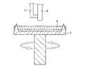
以下、従来のポリシリコン膜のエッチング方法を示す一例について、図1を参照しながら説明する。図1は、シリコン基板1上に半導体装置の要素であるゲート電極を形成するための製造方法の第一段階を示す各工程の断面図である。 Hereinafter, an example of a conventional polysilicon film etching method will be described with reference to FIG. FIG. 1 is a cross-sectional view of each process showing a first stage of a manufacturing method for forming a gate electrode which is an element of a semiconductor device on a silicon substrate 1.
まず、図1(a)に示すように、例えばシリコン基板1の表面に熱酸化膜2を成長させ、続いてポリシリコン3を堆積させる。次に、図1(b)に示すように、裏面に成長したポリシリコン3をウエットエッチングにより除去する。
First, as shown in FIG. 1A, for example, a
この裏面ポリシリコン除去工程は、例えば図30に示すような枚葉式エッチング装置を利用し、フッ硝酸(HF:HNO3=1:80)を用いて30秒間ウエットエッチングを行うことにより行われる。図30において、ウエットエッチングが施されるウエハ4は、ウエハ保持台5上に保持される。ウエハ保持台5の上方に薬液ノズル38が配置され、ウエハ4に対してエッチング液を吐出することによりウエットエッチングが行われる。
しかしながら、従来のポリシリコンのウエットエッチング工程では、図1(b)に示した裏面ポリシリコン除去工程において、ポリシリコン3が均一にエッチングされ難い。
However, in the conventional polysilicon wet etching process, the
具体的には、ポリシリコンのウエットエッチングは、硝酸によるシリコンの酸化とフッ酸によるシリコン酸化膜のエッチングの競争反応により行なわれる。このとき、硝酸とシリコンの酸化反応で、副生成物として生成された二酸化窒素もシリコンを酸化させる。このように2通りのシリコンの酸化反応が行なわれると、硝酸の酸化力より二酸化窒素の酸化力が大きいために、薬液吐出部以外でエッチングが加速して、ポリシリコン膜のエッチングのウエハ面内での均一性が低いという課題が発生する。 Specifically, the wet etching of polysilicon is performed by a competitive reaction between oxidation of silicon by nitric acid and etching of a silicon oxide film by hydrofluoric acid. At this time, nitrogen dioxide generated as a by-product by oxidation reaction of nitric acid and silicon also oxidizes silicon. When the two types of silicon oxidation reactions are performed in this way, since the oxidizing power of nitrogen dioxide is greater than the oxidizing power of nitric acid, the etching is accelerated except in the chemical solution discharge section, and the polysilicon film is etched within the wafer surface. There arises a problem that the uniformity in the is low.
本発明は、上記課題に鑑みてなされたものであり、ウエハ面内での高い均一性をもってポリシリコン膜をウエットエッチングできるエッチング装置、およびエッチング方法を提供することを目的とする。 The present invention has been made in view of the above problems, and an object of the present invention is to provide an etching apparatus and an etching method that can wet-etch a polysilicon film with high uniformity within a wafer surface.
本発明のウエットエッチング装置は、基板上に形成されたポリシリコン膜をウエットエッチングするための装置である。 The wet etching apparatus of the present invention is an apparatus for wet etching a polysilicon film formed on a substrate.
上記課題を解決するために、本発明の第1の構成のウエットエッチング装置は、前記ポリシリコン膜をエッチングするための薬液を吐出するフッ硝酸溶液供給部と、前記フッ硝酸溶液にNO2ガスを混合するNO2ガス供給部とを備える。 In order to solve the above problems, a wet etching apparatus having a first configuration according to the present invention includes a hydrofluoric acid solution supply unit that discharges a chemical solution for etching the polysilicon film, and NO 2 gas is supplied to the hydrofluoric acid solution. And a NO 2 gas supply unit to be mixed.
本発明の第2の構成のウエットエッチング装置は、前記ポリシリコン膜をエッチングするための薬液を吐出するフッ硝酸溶液供給部と、前記フッ硝酸溶液に金属粉末を混合する金属粉末供給部とを備える。 The wet etching apparatus of the second configuration of the present invention includes a hydrofluoric acid solution supply unit that discharges a chemical solution for etching the polysilicon film, and a metal powder supply unit that mixes metal powder into the hydrofluoric acid solution. .
本発明の第3の構成のウエットエッチング装置は、前記ポリシリコン膜をエッチングするための薬液を吐出するフッ硝酸溶液供給部と、前記フッ硝酸溶液に紫外線を照射する紫外線照射部とを備える。 The wet etching apparatus of the third configuration of the present invention includes a hydrofluoric acid solution supply unit that discharges a chemical solution for etching the polysilicon film, and an ultraviolet irradiation unit that irradiates the hydrofluoric acid solution with ultraviolet rays.
本発明のウエットエッチング方法は、基板上に形成されたポリシリコン膜をウエットエッチングするための方法である。 The wet etching method of the present invention is a method for wet etching a polysilicon film formed on a substrate.
上記課題を解決するために、本発明の第1の構成のウエットエッチング方法は、前記ポリシリコン膜をエッチングするためのフッ硝酸溶液にNO2ガスを混合する工程と、前記NO2ガスが混合された前記フッ硝酸溶液を用いて前記ポリシリコン膜をエッチングする工程とを備える。 In order to solve the above problems, a wet etching method according to a first configuration of the present invention includes a step of mixing NO 2 gas with a hydrofluoric acid solution for etching the polysilicon film, and the NO 2 gas is mixed. And etching the polysilicon film using the hydrofluoric acid solution.
本発明の第2の構成のウエットエッチング方法は、前記ポリシリコン膜をエッチングするためのフッ硝酸溶液に金属粉末を混合する工程と、前記金属粉末が混合された前記フッ硝酸溶液を用いて前記ポリシリコン膜をエッチングする工程とを備える。 According to a second aspect of the present invention, there is provided a wet etching method comprising: mixing a metal powder with a hydrofluoric acid solution for etching the polysilicon film; and using the hydrofluoric acid solution mixed with the metal powder, the polynitric acid solution. And a step of etching the silicon film.
本発明の第3の構成のウエットエッチング方法は、前記ポリシリコン膜をエッチングするためのフッ硝酸溶液に紫外線を照射する工程と、前記紫外線が照射された前記フッ硝酸溶液を用いて前記ポリシリコン膜をエッチングする工程とを備える。 According to a third aspect of the present invention, there is provided a wet etching method comprising: irradiating a fluorinated nitric acid solution for etching the polysilicon film with ultraviolet rays; and using the fluorinated nitric acid solution irradiated with the ultraviolet rays, the polysilicon film. Etching.
本発明のエッチング装置およびエッチング方法によれば、薬液吐出部においてもNO2が充分に供給されることになり、ウエハ面全体においてNO2による酸化反応が均一化される。その結果、ウエハ面内におけるポリシリコン膜のウエットエッチングの均一性が改善される。 According to the etching apparatus and the etching method of the present invention, NO 2 is sufficiently supplied also in the chemical solution discharge section, and the oxidation reaction by NO 2 is made uniform over the entire wafer surface. As a result, the uniformity of the wet etching of the polysilicon film within the wafer surface is improved.
上記本発明の第1の構成のウェットエッチング装置において、本ウェットエッチング装置は枚葉式エッチング装置として構成され、前記NO2ガス供給部は、前記フッ硝酸溶液供給部における薬液吐出ノズル内で前記NO2ガスを前記フッ硝酸溶液と混合するように設置されることができる。 In the wet etching apparatus of the first configuration of the present invention, the wet etching apparatus is configured as a single-wafer etching apparatus, and the NO 2 gas supply unit includes the NO 2 in the chemical solution discharge nozzle in the hydrofluoric acid solution supply unit. Two gases can be installed to mix with the hydrofluoric acid solution.
また、本ウェットエッチング装置はバッチ式エッチング装置として構成され、前記NO2ガス供給部は、前記フッ硝酸溶液供給部における薬液供給ライン内で前記NO2ガスを前記フッ硝酸溶液と混合するように設置されることができる。 The wet etching apparatus is configured as a batch type etching apparatus, and the NO 2 gas supply unit is installed so as to mix the NO 2 gas with the hydrofluoric acid solution in a chemical solution supply line in the hydrofluoric acid solution supply unit. Can be done.
また、本ウェットエッチング装置は枚葉式エッチング装置として構成され、前記NO2ガス供給部は、前記NO2ガスと前記フッ硝酸溶液供給部から前記基板に向けて吐出された前記フッ硝酸とを、前記基板上において混合するように設置されることができる。 Further, the present wet etching apparatus is configured as a single wafer etching apparatus, and the NO 2 gas supply unit includes the NO 2 gas and the hydrofluoric acid discharged from the hydrofluoric acid solution supply unit toward the substrate. It can be installed to mix on the substrate.
また、本ウェットエッチング装置は枚葉式エッチング装置として構成され、前記NO2ガス供給部は、エッチングチャンバー内で前記NO2ガスを前記フッ硝酸溶液と混合するように設置されることができる。 The wet etching apparatus may be configured as a single-wafer etching apparatus, and the NO 2 gas supply unit may be installed to mix the NO 2 gas with the hydrofluoric acid solution in an etching chamber.
また、本ウェットエッチング装置はバッチ式エッチング装置として構成され、前記NO2ガス供給部は、エッチング槽内で前記NO2ガスを前記フッ硝酸溶液と混合するように設置されることができる。 The wet etching apparatus may be configured as a batch type etching apparatus, and the NO 2 gas supply unit may be installed to mix the NO 2 gas with the hydrofluoric acid solution in an etching tank.
また、本ウェットエッチング装置は枚葉式エッチング装置またはバッチ式エッチング装置として構成され、前記NO2ガス供給部は、前記フッ硝酸溶液供給部における薬液タンク内で前記NO2ガスを前記フッ硝酸溶液と混合するように設置されることができる。 The wet etching apparatus is configured as a single-wafer etching apparatus or a batch etching apparatus, and the NO 2 gas supply unit converts the NO 2 gas into the hydrofluoric acid solution in a chemical tank in the hydrofluoric acid solution supply unit. Can be installed to mix.
上記本発明の第2の構成のウェットエッチング装置において、本ウェットエッチング装置は枚葉式エッチング装置として構成され、前記金属粉末供給部は、前記フッ硝酸溶液供給部における薬液吐出ノズル内で前記金属粉末を前記フッ硝酸溶液と混合するように設置されることができる。 In the wet etching apparatus of the second configuration of the present invention, the wet etching apparatus is configured as a single-wafer etching apparatus, and the metal powder supply unit is disposed in the chemical solution discharge nozzle in the hydrofluoric acid solution supply unit. To be mixed with the hydrofluoric acid solution.
また、本ウェットエッチング装置はバッチ式エッチング装置として構成され、前記金属粉末供給部は、前記フッ硝酸溶液供給部における薬液供給ライン内で前記金属粉末を前記フッ硝酸溶液と混合するように設置されることができる。 The wet etching apparatus is configured as a batch type etching apparatus, and the metal powder supply unit is installed so as to mix the metal powder with the hydrofluoric acid solution in a chemical solution supply line in the hydrofluoric acid solution supply unit. be able to.
また、前記金属粉末は、Si粉末またはAl粉末とすることができる。 The metal powder may be Si powder or Al powder.
上記本発明の第3の構成のウェットエッチング装置において、本ウェットエッチング装置は枚葉式エッチング装置として構成され、前記紫外線照射部は、前記フッ硝酸溶液供給部における薬液吐出ノズル内を通過する前記フッ硝酸溶液に対して前記紫外線を照射するように設置されることができる。 In the wet etching apparatus of the third configuration of the present invention, the wet etching apparatus is configured as a single-wafer etching apparatus, and the ultraviolet irradiation unit passes through the chemical solution discharge nozzle in the hydrofluoric acid solution supply unit. The nitric acid solution may be installed to irradiate the ultraviolet rays.
また、本ウェットエッチング装置は枚葉式エッチング装置として構成され、前記紫外線照射部は、エッチングチャンバー内に載置された前記基板に向けて前記紫外線を照射するように設置されることができる。 The wet etching apparatus may be configured as a single-wafer etching apparatus, and the ultraviolet irradiation unit may be installed to irradiate the ultraviolet light toward the substrate placed in an etching chamber.
また、本ウェットエッチング装置はバッチ式エッチング装置として構成され、前記紫外線照射部は、エッチング槽内に載置された前記基板に向けて前記紫外線を照射するように設置されることができる。 The wet etching apparatus may be configured as a batch type etching apparatus, and the ultraviolet irradiation unit may be installed so as to irradiate the ultraviolet light toward the substrate placed in an etching tank.
上記本発明の第1の構成のウェットエッチング方法において、本ウェットエッチング方法は枚葉式によりエッチングを行い、前記NO2ガスを、前記フッ硝酸溶液を供給する薬液吐出ノズル内で前記フッ硝酸溶液と混合することができる。 In the wet etching method according to the first aspect of the present invention, the wet etching method is a single wafer etching method, and the NO 2 gas is mixed with the hydrofluoric acid solution in a chemical discharge nozzle for supplying the hydrofluoric acid solution. Can be mixed.
また、本ウェットエッチング方法はバッチ式によりエッチングを行い、前記NO2ガスを、前記フッ硝酸溶液を供給する薬液供給ライン内で前記フッ硝酸溶液と混合することができる。 Further, the present wet etching method can perform batch etching, and the NO 2 gas can be mixed with the hydrofluoric acid solution in a chemical supply line for supplying the hydrofluoric acid solution.
また、本ウェットエッチング方法は枚葉式によりエッチングを行い、前記NO2ガスを、前記基板に向けて吐出された前記フッ硝酸と前記基板上において混合することができる。 Further, the present wet etching method can perform etching by a single wafer method, and the NO 2 gas can be mixed on the substrate with the hydrofluoric acid discharged toward the substrate.
また、本ウェットエッチング方法は枚葉式によりエッチングを行い、前記NO2ガスを、エッチングチャンバー内で前記フッ硝酸溶液と混合することができる。 In addition, the wet etching method can perform etching by a single wafer method, and the NO 2 gas can be mixed with the hydrofluoric acid solution in an etching chamber.
また、本ウェットエッチング方法はバッチ式によりエッチングを行い、前記NO2ガスを、エッチング槽内で前記フッ硝酸溶液と混合することができる。 In addition, the present wet etching method can perform batch etching, and the NO 2 gas can be mixed with the hydrofluoric acid solution in an etching tank.
また、本ウェットエッチング方法は枚葉式またはバッチ式によりエッチングを行い、前記NO2ガスを、前記フッ硝酸溶液を供給する薬液タンク内で前記フッ硝酸溶液と混合することができる。 Further, the present wet etching method performs etching by a single wafer method or a batch method, and the NO 2 gas can be mixed with the hydrofluoric acid solution in a chemical tank that supplies the hydrofluoric acid solution.
上記本発明の第2の構成のウェットエッチング方法において、本ウェットエッチング方法は枚葉式によりエッチングを行い、前記金属粉末を、前記フッ硝酸溶液を供給する薬液吐出ノズル内で前記フッ硝酸溶液と混合することができる。 In the wet etching method according to the second aspect of the present invention, the wet etching method is a single wafer etching method, and the metal powder is mixed with the hydrofluoric acid solution in a chemical discharge nozzle for supplying the hydrofluoric acid solution. can do.
また、本ウェットエッチング方法はバッチ式によりエッチングを行い、前記金属粉末を、前記フッ硝酸溶液を供給する薬液供給ライン内で前記フッ硝酸溶液と混合することができる。 In addition, the wet etching method can perform batch etching, and the metal powder can be mixed with the hydrofluoric acid solution in a chemical supply line for supplying the hydrofluoric acid solution.
また、前記金属粉末が、Si粉末またはAl粉末であることができる。 The metal powder may be Si powder or Al powder.
上記本発明の第3の構成のウェットエッチング方法において、本ウェットエッチング方法は枚葉式によりエッチングを行い、前記紫外線照射を、前記フッ硝酸溶液を供給する薬液吐出ノズル内を通過する前記フッ硝酸溶液に対して行うことができる。 In the wet etching method according to the third aspect of the present invention, the wet etching method performs etching by a single wafer method, and passes the ultraviolet irradiation through the chemical discharge nozzle for supplying the hydrofluoric acid solution. Can be done against.
また、本ウェットエッチング方法は枚葉式によりエッチングを行い、前記紫外線照射を、エッチングチャンバー内に載置された前記基板に向けて行うことができる。 In addition, the wet etching method can perform etching by a single wafer method, and the ultraviolet irradiation can be performed toward the substrate placed in an etching chamber.
また、本ウェットエッチング方法はバッチ式によりエッチングを行い、前記紫外線照射を、エッチング槽内に載置された前記基板に向けて行うことができる。 In addition, the wet etching method can perform batch etching, and the ultraviolet irradiation can be performed toward the substrate placed in an etching tank.
以下に、本発明の各実施形態におけるウエットエッチング装置、及びポリシリコンのウエットエッチング方法について、図面を参照しながら説明する。各実施形態におけるエッチングの適用例である半導体装置の製造方法における工程は、図1に示した断面図を用いて説明する。 Hereinafter, a wet etching apparatus and a polysilicon wet etching method in each embodiment of the present invention will be described with reference to the drawings. The steps in the method of manufacturing a semiconductor device, which is an application example of etching in each embodiment, will be described with reference to the cross-sectional view shown in FIG.
(第1の実施形態)
本発明の第1の実施形態におけるウエットエッチング装置、及びポリシリコンのウエットエッチング方法について、図2を参照して説明する。
(First embodiment)
A wet etching apparatus and a polysilicon wet etching method according to the first embodiment of the present invention will be described with reference to FIG.
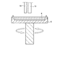
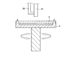
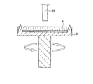
図2は、本実施形態に用いられる枚葉式エッチング装置を示し、ウエハ4は、ウエハ支持台5により支持される。ウエハ支持台5の中央部上方に薬液ノズル6が配置され、ウエハ4に対してエッチング液を吐出することによりウエットエッチングが行われる。薬液ノズル6の射出端部には、NO2供給ライン7が結合されている。
FIG. 2 shows a single wafer etching apparatus used in this embodiment, and the
上記構成のエッチング装置により、図1(b)に示す裏面ポリシリコン除去工程において、ポリシリコン3の裏面を、NO2を添加したフッ硝酸により除去する。すなわち、図2に示すように薬液ノズル6にNO2供給ライン7を併設して、フッ硝酸(HF:HNO3=1:80)の流量1(l/min)に対して、NO2を流量30(l/min)で混合してから吐出し、30秒間ウエットエッチングを行う。NO2供給ライン7を併設することにより、フッ硝酸中のNO2濃度が高くなり、ウエハ4中央部のエッチングが促進され、ウエハ4面内が均一にエッチングされる。
With the etching apparatus having the above configuration, in the backside polysilicon removing step shown in FIG. 1B, the backside of the
以下、フッ硝酸にNO2を混合することでウエハ中央部のエッチングが促進できる理由について説明する。フッ硝酸によるシリコンのエッチングメカニズムは、化学式(1)および(2)で示される。化学式(1)で示されるようにHNO3がSiを酸化し、化学式(2)で示されるようにHFがSiO2をエッチングする。 Hereinafter, the reason why the etching of the central portion of the wafer can be promoted by mixing NO 2 with hydrofluoric acid will be described. The etching mechanism of silicon by hydrofluoric acid is represented by chemical formulas (1) and (2). HNO 3 oxidizes Si as represented by chemical formula (1), and HF etches SiO 2 as represented by chemical formula (2).
Si+4HNO3 → SiO2+4NO2+2H2O (1)
SiO2+6HF → H2SiF6+2H2O (2)
Si + 4HNO 3 → SiO 2 + 4NO 2 + 2H 2 O (1)
SiO 2 + 6HF → H 2 SiF 6 + 2H 2 O (2)
ここで、化学式(1)の反応で副生成物としてNO2が発生する。そして、硝酸の酸化還元電位が1.0Vに対して、NO2は1.6Vであり、非常に酸化力が強い。 Here, NO 2 is generated as a by-product in the reaction of the chemical formula (1). The oxidation-reduction potential of nitric acid is 1.0 V, while NO 2 is 1.6 V, which is very strong in oxidizing power.
NO2を混合しない従来のエッチング方法では、ウエハ中央部に薬液を吐出すると、ウエハ中央部では硝酸の酸化が律速してシリコンのエッチングがほとんど進行しないが、中央部以外(周辺部)ではNO2の酸化によりエッチングが進行する。この結果、ウエハ中央部はシリコンエッチングが遅く、周辺部ではシリコンエッチングが早くなり、ウエハ内でのエッチングの均一性が悪くなる。 In a conventional etching method in which NO 2 is not mixed, when a chemical solution is discharged to the center of the wafer, nitric acid oxidation is rate-limited at the center of the wafer and silicon etching hardly progresses, but NO 2 is not in the center (periphery). Etching progresses due to oxidation. As a result, silicon etching is slow in the central portion of the wafer, and silicon etching is quick in the peripheral portion, resulting in poor uniformity of etching within the wafer.
これに対して本実施形態のように、薬液吐出前にNO2濃度を高くしておけば、ウエハ中央部にもNO2が充分に供給され、ウエハ内のどの部分においてもNO2が酸化反応し、ウエハ面内が均一に酸化され、その結果、ウエハ面内が均一にエッチングできるものと考えられる。 On the other hand, if the NO 2 concentration is increased before the chemical solution is discharged as in this embodiment, the NO 2 is sufficiently supplied to the central portion of the wafer, and the NO 2 is oxidized at any portion in the wafer. Then, it is considered that the wafer surface is uniformly oxidized, and as a result, the wafer surface can be etched uniformly.
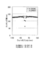
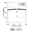
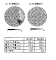
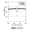
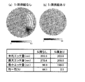
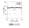
図3は、フッ硝酸でシリコンをエッチングしたときの面内均一性を示すグラフである。このグラフより、NO2を添加しない場合はウエハ中央部のエッチングが不十分で面内均一性が27.4%からであるのに対して、NO2を添加するとウエハ中央部のエッチングが促進され、面内均一性が2.8%まで向上することがわかる。 FIG. 3 is a graph showing in-plane uniformity when silicon is etched with hydrofluoric acid. From this graph, when NO 2 is not added, etching at the center of the wafer is insufficient and the in-plane uniformity is from 27.4%, whereas when NO 2 is added, etching at the center of the wafer is promoted. It can be seen that the in-plane uniformity is improved to 2.8%.
(第2の実施形態)
本発明の第2の実施形態におけるウエットエッチング装置、及びポリシリコンのウエットエッチング方法について、図4を参照して説明する。
(Second Embodiment)
A wet etching apparatus and a polysilicon wet etching method according to the second embodiment of the present invention will be described with reference to FIG.
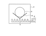
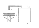
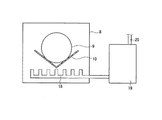
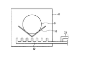
図4は、本実施形態に用いられるバッチ式エッチング装置を示し、エッチング槽8内において、ウエハ9がウエハ支持台10により支持される。ウエハ支持台10の下方に薬液ノズル11が配置され、ウエハ9に対してエッチング液を吐出することによりウエットエッチングが行われる。薬液ノズル11には、NO2供給ライン12が結合されている。
FIG. 4 shows a batch type etching apparatus used in this embodiment, and a
上記構成のエッチング装置により、図1(b)に示す裏面ポリシリコン除去工程において、ポリシリコン3の裏面を、NO2を添加したフッ硝酸で除去する。すなわち、図4に示すように薬液ノズル11にNO2供給ライン12を併設して、フッ硝酸(HF:HNO3=1:80)の流量20(l/min)に対して、NO2を流量30(l/min)で混合してから吐出し、30秒間ウエットエッチングを行う。NO2供給ライン12を併設することにより、フッ硝酸中のNO2濃度が薬液ノズル全体にわたって高くなり、ウエハ9面内が均一にエッチングされる。なお、ここでNO2を混合する効果は、第1の実施形態の場合と同じ理由に基づく。
With the etching apparatus configured as described above, the back surface of the
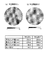
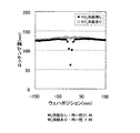
図5は、フッ硝酸でシリコンをエッチングしたときの面内均一性を示すグラフである。このグラフより、NO2を添加しない場合は面内均一性が44.1%と悪いが、NO2を添加すると面内均一性が2.6%まで向上することがわかる。 FIG. 5 is a graph showing in-plane uniformity when silicon is etched with hydrofluoric acid. From this graph, it can be seen that the in-plane uniformity is poor at 44.1% when NO 2 is not added, but the in-plane uniformity is improved to 2.6% when NO 2 is added.
(第3の実施形態)
本発明の第3の実施形態におけるウエットエッチング装置、及びポリシリコンのウエットエッチング方法について、図6を参照して説明する。
(Third embodiment)
A wet etching apparatus and a polysilicon wet etching method according to a third embodiment of the present invention will be described with reference to FIG.
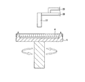
図6は、本実施形態に用いられる枚葉式エッチング装置を示す。上述の装置と同様の要素については同一の参照番号を付して、説明の重複を省略する。本実施形態では、薬液ノズル13にNO2供給ライン14を並列に並べ、ウエハ4にNO2を直接吹きつけるように構成される。
FIG. 6 shows a single wafer etching apparatus used in this embodiment. The same elements as those in the above-described apparatus are denoted by the same reference numerals, and the description will not be repeated. In the present embodiment, the NO 2 supply line 14 is arranged in parallel with the
上記構成のエッチング装置により、図1(b)に示す裏面ポリシリコン除去工程において、ポリシリコン3の裏面を、NO2を添加したフッ硝酸で除去する。すなわち、図6に示すように薬液ノズル13にNO2供給ライン14を並列に並べ、ウエハにNO2を流量30(l/min)で直接吹きつけながら、フッ硝酸(HF:HNO3=1:80)を流量1(l/min)で吐出し、30秒間ウエットエッチングを行う。ウエハ4にNO2を直接吹きつけることにより、フッ硝酸中のNO2濃度が高くなり、ウエハ4中央部のエッチングが促進され、ウエハ4面内が均一にエッチングされる。
With the etching apparatus configured as described above, the back surface of the
NO2を混合する効果は、第1の実施形態の場合と同じ理由に基づく。本実施形態ではフッ硝酸中に直接NO2を混合するわけではないが、フッ硝酸とNO2を並列してウエハに向けて放出することで、気相中で両者が混合されることになる。 The effect of mixing NO 2 is based on the same reason as in the first embodiment. In the present embodiment, NO 2 is not directly mixed into the hydrofluoric acid, but both are mixed in the gas phase by releasing the hydrofluoric acid and NO 2 toward the wafer in parallel.
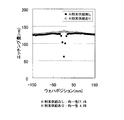
図7は、フッ硝酸でシリコンをエッチングしたときの面内均一性を示すグラフである。このグラフより、NO2を添加しない場合はウエハ中央部のエッチングが不十分で面内均一性が27.4%であるのに対して、NO2を添加するとウエハ中央部のエッチングが促進され、面内均一性が4.0%まで向上することがわかる。 FIG. 7 is a graph showing in-plane uniformity when silicon is etched with hydrofluoric acid. From this graph, when NO 2 is not added, etching at the wafer center is insufficient and the in-plane uniformity is 27.4%, whereas when NO 2 is added, etching at the wafer center is promoted, It can be seen that the in-plane uniformity is improved to 4.0%.
(第4の実施形態)
本発明の第4の実施形態におけるウエットエッチング装置、及びポリシリコンのウエットエッチング方法について、図8を参照して説明する。
(Fourth embodiment)
A wet etching apparatus and a polysilicon wet etching method according to the fourth embodiment of the present invention will be described with reference to FIG.
図8は、本実施形態に用いられる枚葉式エッチング装置を示す。上述の装置と同様の要素については同一の参照番号を付して、説明の重複を省略する。本実施形態では、薬液ノズル15に薬液を供給する薬液タンク16に、NO2供給ライン17が併設される。NO2供給ライン17から、薬液タンク16中のフッ硝酸(HF:HNO3=1:80)にNO2を溶け込ませて、飽和状態にする。
FIG. 8 shows a single wafer etching apparatus used in this embodiment. The same elements as those in the above-described apparatus are denoted by the same reference numerals, and the description will not be repeated. In the present embodiment, a NO 2
上記構成のエッチング装置により、図1(b)に示す裏面ポリシリコン除去工程において、ポリシリコン3の裏面を、NO2を添加したフッ硝酸で除去する。すなわち、図8に示すように、薬液タンク16にNO2供給ライン85を併設して、NO2を飽和状態に溶け込ませたフッ硝酸を流量1(l/min)で薬液ノズル15から吐出し、30秒間ウエットエッチングを行なう。NO2を飽和状態に溶け込ませたフッ硝酸を用いることにより、フッ硝酸中のNO2濃度が薬液ノズル全体にわたって高くなり、ウエハ4面内が均一にエッチングされる。なお、NO2を混合する効果は、第1の実施形態の場合と同じ理由に基づく。
With the etching apparatus configured as described above, the back surface of the
図9は、フッ硝酸でシリコンをエッチングしたときの面内均一性を示すグラフである。
このグラフより、NO2を添加しない場合はウエハ中央部のエッチングが不十分で面内均一性が27.4%であるのに対して、NO2を添加するとウエハ中央部のエッチングが促進され、面内均一性が2.8%まで向上することがわかる。
(第5の実施形態)
本発明の第5の実施形態におけるウエットエッチング装置、及びポリシリコンのウエットエッチング方法について、図10を参照して説明する。
FIG. 9 is a graph showing in-plane uniformity when silicon is etched with hydrofluoric acid.
From this graph, when NO 2 is not added, etching at the center of the wafer is insufficient and the in-plane uniformity is 27.4%, whereas when NO 2 is added, etching at the center of the wafer is promoted. It can be seen that the in-plane uniformity is improved to 2.8%.
(Fifth embodiment)
A wet etching apparatus and a polysilicon wet etching method according to a fifth embodiment of the present invention will be described with reference to FIG.
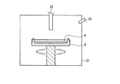
図10は、本実施形態に用いられるバッチ式エッチング装置を示す。上述の装置と同様の要素については同一の参照番号を付して、説明の重複を省略する。本実施形態では、薬液ノズル18に薬液を供給する薬液タンク19に、NO2供給ライン20が併設される。
FIG. 10 shows a batch type etching apparatus used in this embodiment. The same elements as those in the above-described apparatus are denoted by the same reference numerals, and the description will not be repeated. In the present embodiment, a NO 2 supply line 20 is provided along with a
上記構成のエッチング装置により、図1(b)に示す裏面ポリシリコン除去工程において、ポリシリコン3の裏面を、NO2を添加したフッ硝酸で除去する。すなわち、図10に示すように、NO2供給ライン20からフッ硝酸(HF:HNO3=1:80)にNO2を溶け込ませて、飽和状態にする。このNO2を飽和状態に溶け込ませたフッ硝酸を流量20(l/min)で薬液ノズル18から吐出し、30秒間ウエットエッチングを行なう。これにより、フッ硝酸中のNO2濃度が薬液ノズル18全体にわたって高くなり、ウエハ9面内が均一にエッチングされる。NO2を混合する効果は、第1の実施形態の場合と同じ理由に基づく。
With the etching apparatus configured as described above, the back surface of the
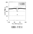
図11は、フッ硝酸でシリコンをエッチングしたときの面内均一性を示すグラフである。このグラフより、NO2を添加しない状態では面内均一性が44.1%と悪いが、NO2を添加すると面内均一性が2.6%まで向上することがわかる。 FIG. 11 is a graph showing in-plane uniformity when silicon is etched with hydrofluoric acid. From this graph, it can be seen that the in-plane uniformity is as bad as 44.1% in the state where NO 2 is not added, but the in-plane uniformity is improved to 2.6% when NO 2 is added.
(第6の実施形態)
本発明の第6の実施形態におけるウエットエッチング装置、及びポリシリコンのウエットエッチング方法について、図12を参照して説明する。
(Sixth embodiment)
A wet etching apparatus and a polysilicon wet etching method according to a sixth embodiment of the present invention will be described with reference to FIG.
図12は、本実施形態に用いられる枚葉式エッチング装置を示す。上述の装置と同様の要素については同一の参照番号を付して、説明の重複を省略する。本実施形態では、エッチングチャンバー21に、薬液ノズル22とNO2供給ライン23が併設される。
FIG. 12 shows a single wafer etching apparatus used in the present embodiment. The same elements as those in the above-described apparatus are denoted by the same reference numerals, and the description will not be repeated. In the present embodiment, the
上記構成のエッチング装置により、図1(b)に示す裏面ポリシリコン除去工程において、ポリシリコン3の裏面を、フッ硝酸で除去する。これ自体は従来技術と同様であるが、本実施形態においてはさらに、NO2供給ライン23により、エッチングチャンバー21内をNO2雰囲気にする。このNO2雰囲気の中で、ポリシリコン3の裏面を、フッ硝酸(HF:HNO3=1:80)を流量1(l/min)で用いて30秒間ウエットエッチングを行う。これにより、エッチングチャンバー21内のNO2濃度が高くなり、ウエハ4面内が均一にエッチングされる。
With the etching apparatus having the above configuration, the back surface of the
NO2を混合する効果は、第1の実施形態の場合と同じ理由に基づく。本実施形態ではフッ硝酸中に直接NO2を混合するわけではないが、フッ硝酸をNO2雰囲気下でウエハに向けて吐出することで、気相中で両者が混合されることになる。 The effect of mixing NO 2 is based on the same reason as in the first embodiment. In the present embodiment, NO 2 is not directly mixed into the fluorinated nitric acid, but both are mixed in the gas phase by discharging the fluorinated nitric acid toward the wafer in an NO 2 atmosphere.
図13は、フッ硝酸でシリコンをエッチングしたときの面内均一性を示すグラフである。このグラフより、NO2を添加しない場合はウエハ中央部のエッチングが不十分で面内均一性が27.4%であるのに対して、NO2を添加するとウエハ中央部のエッチングが促進され、面内均一性が2.8%まで向上することがわかる。 FIG. 13 is a graph showing in-plane uniformity when silicon is etched with hydrofluoric acid. From this graph, when NO 2 is not added, etching at the center of the wafer is insufficient and the in-plane uniformity is 27.4%, whereas when NO 2 is added, etching at the center of the wafer is promoted. It can be seen that the in-plane uniformity is improved to 2.8%.
(第7の実施形態)
本発明の第7の実施形態におけるウエットエッチング装置、及びポリシリコンのウエットエッチング方法について、図14を参照して説明する。
(Seventh embodiment)
A wet etching apparatus and a polysilicon wet etching method according to a seventh embodiment of the present invention will be described with reference to FIG.
図14は、本実施形態に用いられるバッチ式エッチング装置を示す。上述の装置と同様の要素については同一の参照番号を付して、説明の重複を省略する。本実施形態では、エッチング槽8に、薬液ノズル18とNO2供給ライン24が併設される。
FIG. 14 shows a batch type etching apparatus used in this embodiment. The same elements as those in the above-described apparatus are denoted by the same reference numerals, and the description will not be repeated. In the present embodiment, the
上記構成のエッチング装置により、図1(b)に示す裏面ポリシリコン除去工程において、ポリシリコン3の裏面を、NO2を添加したフッ硝酸で除去する。すなわち、NO2供給ライン24から薬液中にNO2ガスを供給し、30秒間ウエットエッチングを行なう。これにより薬液中のNO2濃度がエッチング槽8全体にわたって高くなり、ウエハ9面内が均一にエッチングされる。NO2を混合する効果は、第1の実施形態の場合と同じ理由に基づく。
With the etching apparatus configured as described above, the back surface of the
図15は、フッ硝酸でシリコンをエッチングしたときの面内均一性を示すグラフである。このグラフより、NO2を添加しない状態では面内均一性が44.1%と悪いが、NO2を添加すると面内均一性が2.6%まで向上することがわかる。 FIG. 15 is a graph showing in-plane uniformity when silicon is etched with hydrofluoric acid. From this graph, it can be seen that the in-plane uniformity is as bad as 44.1% in the state where NO 2 is not added, but the in-plane uniformity is improved to 2.6% when NO 2 is added.
(第8の実施形態)
本発明の第8の実施形態におけるウエットエッチング装置、及びポリシリコンのウエットエッチング方法について、図16を参照して説明する。
(Eighth embodiment)
A wet etching apparatus and a polysilicon wet etching method according to an eighth embodiment of the present invention will be described with reference to FIG.
図16は、本実施形態に用いられる枚葉式エッチング装置を示す。上述の装置と同様の要素については同一の参照番号を付して、説明の重複を省略する。本実施形態では、薬液ノズル25にSi粉末供給ライン26が併設される。
FIG. 16 shows a single wafer etching apparatus used in this embodiment. The same elements as those in the above-described apparatus are denoted by the same reference numerals, and the description will not be repeated. In the present embodiment, a Si
上記構成のエッチング装置により、図1(b)に示す裏面ポリシリコン除去工程において、ポリシリコン3の裏面を、Si粉末を混合したフッ硝酸で除去する。すなわち、薬液ノズル25にSi粉末供給ライン26を併設することにより、フッ硝酸(HF:HNO3=1:80)を流量1(l/min)でSi粉末を混合してから吐出し、30秒間ウエットエッチングを行う。これにより、結果的にフッ硝酸中のNO2濃度が高くなり、ウエハ4中央部のエッチングが促進され、ウエハ面内が均一にエッチングされる。
With the etching apparatus configured as described above, the back surface of the
以下、フッ硝酸にSi粉末を混合することでウエハ中央部のエッチングが促進できる理由を説明する。フッ硝酸にSi粉末を混合することにより、まずフッ硝酸がSi粉末をエッチングする。この反応過程で上記化学式(1)に示すように、NO2が副生成物として生成され、これによりフッ硝酸中のNO2濃度が高くなる。以降のエッチングメカニズムは第1の実施形態について説明したとおりであり、ウエハ面内が均一にエッチングされることになる。 Hereinafter, the reason why the etching of the wafer central portion can be promoted by mixing Si powder with hydrofluoric acid will be described. By mixing Si powder with hydrofluoric acid, first, the hydrofluoric acid etches the Si powder. In this reaction process, as shown in the chemical formula (1), NO 2 is produced as a by-product, thereby increasing the concentration of NO 2 in the hydrofluoric acid. The subsequent etching mechanism is as described in the first embodiment, and the wafer surface is uniformly etched.
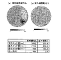
図17は、フッ硝酸でシリコンをエッチングしたときの面内均一性を示すグラフである。このグラフより、Si粉末を混合しない場合はウエハ中央部のエッチングが不十分で面内均一性が27.4%であるのに対して、Si粉末を混合するとウエハ中央部のエッチングが促進され、面内均一性が4.0%まで向上することがわかる。 FIG. 17 is a graph showing in-plane uniformity when silicon is etched with hydrofluoric acid. From this graph, when the Si powder is not mixed, the etching at the wafer center is insufficient and the in-plane uniformity is 27.4%, whereas when the Si powder is mixed, the etching at the wafer center is promoted. It can be seen that the in-plane uniformity is improved to 4.0%.
(第9の実施形態)
本発明の第9の実施形態におけるウエットエッチング装置、及びポリシリコンのウエットエッチング方法について、図18を参照して説明する。
(Ninth embodiment)
A wet etching apparatus and a polysilicon wet etching method according to the ninth embodiment of the present invention will be described with reference to FIG.
図18は、本実施形態に用いられる枚葉式エッチング装置を示す。上述の装置と同様の要素については同一の参照番号を付して、説明の重複を省略する。本実施形態では、薬液ノズル27にエッチング液を供給する薬液ライン28に、Al粉末供給ライン29が併設される。
FIG. 18 shows a single wafer etching apparatus used in the present embodiment. The same elements as those in the above-described apparatus are denoted by the same reference numerals, and the description will not be repeated. In the present embodiment, an Al
上記構成のエッチング装置により、図1(b)に示す裏面ポリシリコン除去工程において、ポリシリコン3の裏面を、Al粉末を混合したフッ硝酸で除去する。すなわち、薬液ライン28にAl粉末供給ライン29を併設することにより、フッ硝酸(HF:HNO3=1:80)を流量1(l/min)でAl粉末を混合してから吐出し、30秒間ウエットエッチングを行う。これにより、結果的にフッ硝酸中のNO2濃度が高くなり、ウエハ4中央部のエッチングが促進され、ウエハ4面内が均一にエッチングされる。
With the etching apparatus having the above-described configuration, the back surface of the
以下、フッ硝酸にAl粉末を混合することでウエハ中央部のエッチングが促進できる理由を説明する。フッ硝酸にAl粉末を混合することにより、まずAlと硝酸が以下の化学式(3)の反応をする。 Hereinafter, the reason why the etching of the central portion of the wafer can be promoted by mixing Al powder with hydrofluoric acid will be described. By mixing Al powder with hydrofluoric acid, first, Al and nitric acid react by the following chemical formula (3).
2Al+2HNO3→Al2O3+H2O+NO2 (3) 2Al + 2HNO 3 → Al 2 O 3 + H 2 O + NO 2 (3)
化学式(3)の反応によりNO2が生成され、これによりフッ硝酸中のNO2濃度が高くなる。以降のエッチングメカニズムは第1の実施形態において説明したとおりであり、ウエハ面内が均一にエッチングされることになる。 NO 2 is produced by the reaction of the chemical formula (3), thereby increasing the concentration of NO 2 in the hydrofluoric acid. The subsequent etching mechanism is as described in the first embodiment, and the wafer surface is uniformly etched.
図19は、フッ硝酸でシリコンをエッチングしたときの面内均一性を示すグラフである。このグラフより、Al粉末を混合しない場合はウエハ中央部のエッチングが不十分で面内均一性が27.4%であるのに対して、Al粉末を混合するとウエハ中央部のエッチングが促進され、面内均一性が4.0%まで向上することがわかる。 FIG. 19 is a graph showing in-plane uniformity when silicon is etched with hydrofluoric acid. From this graph, when Al powder is not mixed, etching at the wafer center is insufficient and in-plane uniformity is 27.4%, whereas when Al powder is mixed, etching at the wafer center is promoted, It can be seen that the in-plane uniformity is improved to 4.0%.
(第10の実施形態)
本発明の第10の実施形態におけるウエットエッチング装置、及びポリシリコンのウエットエッチング方法について、図20を参照して説明する。
(Tenth embodiment)
A wet etching apparatus and a polysilicon wet etching method according to a tenth embodiment of the present invention will be described with reference to FIG.
図20は、本実施形態に用いられるバッチ式エッチング装置を示す。上述の装置と同様の要素については同一の参照番号を付して、説明の重複を省略する。本実施形態では、薬液ノズル30への薬液供給ラインにSi粉末供給ライン31が併設される。
FIG. 20 shows a batch type etching apparatus used in this embodiment. The same elements as those in the above-described apparatus are denoted by the same reference numerals, and the description will not be repeated. In the present embodiment, a Si
上記構成のエッチング装置により、図1(b)に示す裏面ポリシリコン除去工程において、ポリシリコン3の裏面を、Si粉末を混合したフッ硝酸で除去する。すなわち、薬液供給ラインにSi粉末供給ライン31を併設して、フッ硝酸(HF:HNO3=1:80)を流量20(l/min)でSi粉末を混合してから吐出し、30秒間ウエットエッチングを行う。これにより、結果的にフッ硝酸中のNO2濃度が高くなり、ウエハ9面内が均一にエッチングされる。Si粉末を混合する効果は、第8の実施形態の場合と同じ理由に基づく。
With the etching apparatus configured as described above, the back surface of the
図21は、フッ硝酸でシリコンをエッチングしたときの面内均一性を示すグラフである。このグラフより、Si粉末を混合しない状態では面内均一性が44.1%と悪いが、Si粉末を混合すると面内均一性が2.5%まで向上することがわかる。 FIG. 21 is a graph showing in-plane uniformity when silicon is etched with hydrofluoric acid. From this graph, it can be seen that the in-plane uniformity is as bad as 44.1% in the state where the Si powder is not mixed, but the in-plane uniformity is improved to 2.5% when the Si powder is mixed.
(第11の実施形態)
本発明の第11の実施形態におけるウエットエッチング装置、及びポリシリコンのウエットエッチング方法について、図22を参照して説明する。
(Eleventh embodiment)
A wet etching apparatus and a polysilicon wet etching method according to an eleventh embodiment of the present invention will be described with reference to FIG.
図22は、本実施形態に用いられるバッチ式エッチング装置を示す。上述の装置と同様の要素については同一の参照番号を付して、説明の重複を省略する。本実施形態では、薬液ノズル32への薬液供給ラインにAl粉末供給ライン33が併設される。
FIG. 22 shows a batch type etching apparatus used in this embodiment. The same elements as those in the above-described apparatus are denoted by the same reference numerals, and the description will not be repeated. In the present embodiment, an Al
上記構成のエッチング装置により、図1(b)に示す裏面ポリシリコン除去工程において、ポリシリコン3の裏面を、Al粉末を混合したフッ硝酸で除去する。すなわち、薬液ラインにAl粉末供給ライン33を併設して、フッ硝酸(HF:HNO3=1:80)を流量20(l/min)でAl粉末を混合してから吐出し、30秒間ウエットエッチングを行う。これにより、結果的にフッ硝酸中のNO2濃度が高くなり、ウエハ9面内が均一にエッチングされる。Al粉末を混合する効果は、第9の実施形態の場合と同じ理由に基づく。
With the etching apparatus having the above configuration, in the backside polysilicon removing step shown in FIG. 1B, the backside of the
図23は、フッ硝酸でシリコンをエッチングしたときの面内均一性を示すグラフである。このグラフより、Al粉末を混合しない状態では面内均一性が44.1%と悪いが、Al粉末を混合すると面内均一性が2.5%まで向上することがわかる。 FIG. 23 is a graph showing in-plane uniformity when silicon is etched with hydrofluoric acid. From this graph, it can be seen that in-plane uniformity is poor at 44.1% in the state where no Al powder is mixed, but in-plane uniformity is improved to 2.5% when Al powder is mixed.
(第12の実施形態)
本発明の第12の実施形態におけるウエットエッチング装置、及びポリシリコンのウエットエッチング方法について、図24を参照して説明する。
(Twelfth embodiment)
A wet etching apparatus and a polysilicon wet etching method according to a twelfth embodiment of the present invention will be described with reference to FIG.
図24は、本実施形態に用いられる枚葉式エッチング装置を示す。上述の装置と同様の要素については同一の参照番号を付して、説明の重複を省略する。本実施形態では、薬液ノズル34に紫外線照射装置35が併設される。
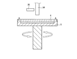
FIG. 24 shows a single wafer etching apparatus used in this embodiment. The same elements as those in the above-described apparatus are denoted by the same reference numerals, and the description will not be repeated. In the present embodiment, an
上記構成のエッチング装置により、図1(b)に示す裏面ポリシリコン除去工程において、ポリシリコン3の裏面をフッ硝酸で除去するが、その際にフッ硝酸に紫外線を照射する。すなわち、紫外線照射装置35により、フッ硝酸(HF:HNO3=1:80)を流量1(l/min)で波長220nmの紫外線をさせてから吐出する。これにより、フッ硝酸中の硝酸が光分解し、NO2が発生して、結果的にフッ硝酸中のNO2濃度が高くなり、ウエハ4中央部のエッチングが促進され、ウエハ面内が均一にエッチングされる。
With the etching apparatus having the above-described configuration, the back surface of the
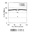
図25は、フッ硝酸でシリコンをエッチングしたときの面内均一性を示すグラフである。このグラフより、紫外線を照射しない場合はウエハ中央部のエッチングが不十分で面内均一性が27.4%であるのに対して、紫外線を照射するとウエハ中央部のエッチングが促進され、面内均一性が2.8%まで向上することがわかる。 FIG. 25 is a graph showing in-plane uniformity when silicon is etched with hydrofluoric acid. From this graph, when the ultraviolet ray is not irradiated, the etching at the central portion of the wafer is insufficient and the in-plane uniformity is 27.4%, whereas when the ultraviolet ray is irradiated, the etching at the central portion of the wafer is promoted. It can be seen that the uniformity is improved to 2.8%.
(第13の実施形態)
本発明の第13の実施形態におけるウエットエッチング装置、及びポリシリコンのウエットエッチング方法について、図26を参照して説明する。
(13th Embodiment)
A wet etching apparatus and a polysilicon wet etching method according to a thirteenth embodiment of the present invention will be described with reference to FIG.
図26は、本実施形態に用いられる枚葉式エッチング装置を示す。上述の装置と同様の要素については同一の参照番号を付して、説明の重複を省略する。本実施形態では、エッチングチャンバー21に紫外線照射装置36が設置される。
FIG. 26 shows a single wafer etching apparatus used in this embodiment. The same elements as those in the above-described apparatus are denoted by the same reference numerals, and the description will not be repeated. In the present embodiment, an
上記構成のエッチング装置により、図1(b)に示す裏面ポリシリコン除去工程において、ポリシリコン3の裏面をフッ硝酸で除去するが、その際にウエハに紫外線を照射する。すなわち、紫外線照射装置36からウエハ4に波長220nmの紫外線を照射させながら、薬液ノズル22からフッ硝酸を流量1(l/min)で吐出する。これにより、フッ硝酸中の硝酸が光分解し、NO2が発生して、結果的にフッ硝酸中のNO2濃度が高くなり、ウエハ4中央部のエッチングが促進され、ウエハ面内が均一にエッチングされる。
With the etching apparatus having the above-described configuration, the back surface of the
図27は、フッ硝酸でシリコンをエッチングしたときの面内均一性を示すグラフである。このグラフより、紫外線を照射しない場合はウエハ中央部のエッチングが不十分で面内均一性が27.4%であるのに対して、紫外線を照射するとウエハ中央部のエッチングが促進され、面内均一性が2.8%まで向上することがわかる。 FIG. 27 is a graph showing in-plane uniformity when silicon is etched with hydrofluoric acid. From this graph, when the ultraviolet ray is not irradiated, the etching at the central portion of the wafer is insufficient and the in-plane uniformity is 27.4%, whereas when the ultraviolet ray is irradiated, the etching at the central portion of the wafer is promoted. It can be seen that the uniformity is improved to 2.8%.
(第14の実施形態)
本発明の第14の実施形態におけるウエットエッチング装置、及びポリシリコンのウエットエッチング方法について、図28を参照して説明する。
(Fourteenth embodiment)
A wet etching apparatus and a polysilicon wet etching method according to a fourteenth embodiment of the present invention will be described with reference to FIG.
図28は、本実施形態に用いられるバッチ式エッチング装置を示す。上述の装置と同様の要素については同一の参照番号を付して、説明の重複を省略する。本実施形態では、エッチング槽8に紫外線照射装置37が設置される。
FIG. 28 shows a batch type etching apparatus used in this embodiment. The same elements as those in the above-described apparatus are denoted by the same reference numerals, and the description will not be repeated. In the present embodiment, an
上記構成のエッチング装置により、図1(b)に示す裏面ポリシリコン除去工程において、ポリシリコン3の裏面をフッ硝酸で除去するが、その際にウエハに紫外線を照射する。すなわち、紫外線照射装置37からウエハ9に波長220nmの紫外線を照射させながら、薬液ノズル18からフッ硝酸を流量20(l/min)で吐出する。これにより、フッ硝酸中の硝酸が光分解し、NO2が発生して、結果的にフッ硝酸中のNO2濃度が高くなり、ウエハ9中央部のエッチングが促進され、ウエハ面内が均一にエッチングされる。
With the etching apparatus having the above-described configuration, the back surface of the
図29は、フッ硝酸でシリコンをエッチングしたときの面内均一性を示すグラフである。このグラフより、紫外線を照射しない状態では面内均一性が44.1%と悪いが、紫外線を照射すると面内均一性が2.6%まで向上することがわかる。 FIG. 29 is a graph showing in-plane uniformity when silicon is etched with hydrofluoric acid. From this graph, it can be seen that the in-plane uniformity is poor at 44.1% in the state where no ultraviolet rays are irradiated, but the in-plane uniformity is improved to 2.6% when the ultraviolet rays are irradiated.
本発明のエッチング装置およびエッチング方法は、ウエハ面内においてポリシリコン膜を均一にウエットエッチングすることを可能とするものであり、特に、ウエハ裏面上に形成されたポリシリコン膜のウエットエッチング等に有効である。 INDUSTRIAL APPLICABILITY The etching apparatus and etching method of the present invention enables wet etching of a polysilicon film uniformly within a wafer surface, and is particularly effective for wet etching of a polysilicon film formed on the back surface of a wafer. It is.
1 シリコン基板
2 熱酸化膜
3 ポリシリコン
4、9 ウエハ
5、10 ウエハ保持台
6、11、13、15、18、22、25、27、30、32、34、38 薬液ノズル
7、12、14、23、24 NO2供給ライン
8 エッチング槽
21 エッチングチャンバー
17、20 NO2供給ノズル
16、19 薬液タンク
26、31 Si粉末供給ライン
28 薬液供給ライン
29、33 Al粉末供給ライン
35、36、37 紫外線照射装置
DESCRIPTION OF SYMBOLS 1
Claims (30)
前記ポリシリコン膜をエッチングするための薬液を吐出するフッ硝酸溶液供給部と、
前記フッ硝酸溶液にNO2ガスを混合するNO2ガス供給部とを備えたウエットエッチング装置。 An apparatus for wet etching a polysilicon film formed on a substrate,
A hydrofluoric acid solution supply unit for discharging a chemical for etching the polysilicon film;
A wet etching apparatus comprising: a NO 2 gas supply unit that mixes NO 2 gas with the hydrofluoric acid solution.
前記NO2ガス供給部は、前記フッ硝酸溶液供給部における薬液吐出ノズル内で前記NO2ガスを前記フッ硝酸溶液と混合するように設置されている請求項1に記載のウエットエッチング装置。 The wet etching apparatus is configured as a single wafer etching apparatus,
2. The wet etching apparatus according to claim 1, wherein the NO 2 gas supply unit is installed so as to mix the NO 2 gas with the hydrofluoric acid solution in a chemical solution discharge nozzle in the hydrofluoric acid solution supply unit.
前記NO2ガス供給部は、前記フッ硝酸溶液供給部における薬液供給ライン内で前記NO2ガスを前記フッ硝酸溶液と混合するように設置されている請求項1に記載のウエットエッチング装置。 The wet etching apparatus is configured as a batch type etching apparatus,
2. The wet etching apparatus according to claim 1, wherein the NO 2 gas supply unit is installed so as to mix the NO 2 gas with the hydrofluoric acid solution in a chemical solution supply line in the hydrofluoric acid solution supply unit.
前記NO2ガス供給部は、前記NO2ガスと前記フッ硝酸溶液供給部から前記基板に向けて吐出された前記フッ硝酸とを、前記基板上において混合するように設置されている請求項1に記載のウエットエッチング装置。 The wet etching apparatus is configured as a single wafer etching apparatus,
The NO 2 gas supply unit, and said hydrofluoric nitric discharged toward the substrate from the NO 2 gas and the hydrofluoric-nitric acid solution supply section, in claim 1 which is installed to mix in said substrate The wet etching apparatus as described.
前記NO2ガス供給部は、エッチングチャンバー内で前記NO2ガスを前記フッ硝酸溶液と混合するように設置されている請求項1に記載のウエットエッチング装置。 The wet etching apparatus is configured as a single wafer etching apparatus,
The wet etching apparatus according to claim 1, wherein the NO 2 gas supply unit is installed so as to mix the NO 2 gas with the hydrofluoric acid solution in an etching chamber.
前記NO2ガス供給部は、エッチング槽内で前記NO2ガスを前記フッ硝酸溶液と混合するように設置されている請求項1に記載のウエットエッチング装置。 The wet etching apparatus is configured as a batch type etching apparatus,
2. The wet etching apparatus according to claim 1, wherein the NO 2 gas supply unit is installed so as to mix the NO 2 gas with the hydrofluoric acid solution in an etching tank.
前記NO2ガス供給部は、前記フッ硝酸溶液供給部における薬液タンク内で前記NO2ガスを前記フッ硝酸溶液と混合するように設置されている請求項1に記載のウエットエッチング装置。 The wet etching apparatus is configured as a single wafer etching apparatus or a batch etching apparatus,
2. The wet etching apparatus according to claim 1, wherein the NO 2 gas supply unit is installed to mix the NO 2 gas with the hydrofluoric acid solution in a chemical tank in the hydrofluoric acid solution supply unit.
前記ポリシリコン膜をエッチングするための薬液を吐出するフッ硝酸溶液供給部と、
前記フッ硝酸溶液に金属粉末を混合する金属粉末供給部とを備えたウエットエッチング装置。 An apparatus for wet etching a polysilicon film formed on a substrate,
A hydrofluoric acid solution supply unit for discharging a chemical for etching the polysilicon film;
A wet etching apparatus comprising a metal powder supply unit that mixes metal powder with the hydrofluoric acid solution.
前記金属粉末供給部は、前記フッ硝酸溶液供給部における薬液吐出ノズル内で前記金属粉末を前記フッ硝酸溶液と混合するように設置されている請求項8に記載のウエットエッチング装置。 The wet etching apparatus is configured as a single wafer etching apparatus,
The wet etching apparatus according to claim 8, wherein the metal powder supply unit is installed so as to mix the metal powder with the hydrofluoric acid solution in a chemical solution discharge nozzle in the hydrofluoric acid solution supply unit.
前記金属粉末供給部は、前記フッ硝酸溶液供給部における薬液供給ライン内で前記金属粉末を前記フッ硝酸溶液と混合するように設置されている請求項8に記載のウエットエッチング装置。 The wet etching apparatus is configured as a batch type etching apparatus,
The wet etching apparatus according to claim 8, wherein the metal powder supply unit is installed to mix the metal powder with the hydrofluoric acid solution in a chemical solution supply line in the hydrofluoric acid solution supply unit.
前記ポリシリコン膜をエッチングするための薬液を吐出するフッ硝酸溶液供給部と、
前記フッ硝酸溶液に紫外線を照射する紫外線照射部とを備えたウエットエッチング装置。 An apparatus for wet etching a polysilicon film formed on a substrate,
A hydrofluoric acid solution supply unit for discharging a chemical for etching the polysilicon film;
A wet etching apparatus comprising: an ultraviolet irradiation unit that irradiates the hydrofluoric acid solution with ultraviolet rays.
前記紫外線照射部は、前記フッ硝酸溶液供給部における薬液吐出ノズル内を通過する前記フッ硝酸溶液に対して前記紫外線を照射するように設置されている請求項12に記載のウエットエッチング装置。 The wet etching apparatus is configured as a single wafer etching apparatus,
The wet etching apparatus according to claim 12, wherein the ultraviolet irradiation unit is installed so as to irradiate the ultraviolet light with respect to the hydrofluoric acid solution passing through a chemical solution discharge nozzle in the hydrofluoric acid solution supply unit.
前記紫外線照射部は、エッチングチャンバー内に載置された前記基板に向けて前記紫外線を照射するように設置されている請求項12に記載のウエットエッチング装置。 The wet etching apparatus is configured as a single wafer etching apparatus,
The wet etching apparatus according to claim 12, wherein the ultraviolet irradiation unit is disposed so as to irradiate the ultraviolet light toward the substrate placed in an etching chamber.
前記紫外線照射部は、エッチング槽内に載置された前記基板に向けて前記紫外線を照射するように設置されている請求項12に記載のウエットエッチング装置。 The wet etching apparatus is configured as a batch type etching apparatus,
The wet etching apparatus according to claim 12, wherein the ultraviolet irradiation unit is installed so as to irradiate the ultraviolet light toward the substrate placed in an etching tank.
前記ポリシリコン膜をエッチングするためのフッ硝酸溶液にNO2ガスを混合する工程と、
前記NO2ガスが混合された前記フッ硝酸溶液を用いて前記ポリシリコン膜をエッチングする工程とを備えたウエットエッチング方法。 A method for wet etching a polysilicon film formed on a substrate,
Mixing NO 2 gas with a hydrofluoric acid solution for etching the polysilicon film;
And a step of etching the polysilicon film using the hydrofluoric acid solution mixed with the NO 2 gas.
前記NO2ガスを、前記フッ硝酸溶液を供給する薬液吐出ノズル内で前記フッ硝酸溶液と混合する請求項16に記載のウエットエッチング方法。 The wet etching method performs etching by a single wafer type,
The wet etching method according to claim 16, wherein the NO 2 gas is mixed with the hydrofluoric acid solution in a chemical solution discharge nozzle that supplies the hydrofluoric acid solution.
前記NO2ガスを、前記フッ硝酸溶液を供給する薬液供給ライン内で前記フッ硝酸溶液と混合する請求項16に記載のウエットエッチング方法。 The wet etching method performs batch-type etching,
The wet etching method according to claim 16, wherein the NO 2 gas is mixed with the hydrofluoric acid solution in a chemical solution supply line that supplies the hydrofluoric acid solution.
前記NO2ガスを、前記基板に向けて吐出された前記フッ硝酸と前記基板上において混合する請求項16に記載のウエットエッチング方法。 The wet etching method performs etching by a single wafer type,
The wet etching method according to claim 16, wherein the NO 2 gas is mixed on the substrate with the hydrofluoric acid discharged toward the substrate.
前記NO2ガスを、エッチングチャンバー内で前記フッ硝酸溶液と混合する請求項16に記載のウエットエッチング方法。 The wet etching method performs etching by a single wafer type,
The wet etching method according to claim 16, wherein the NO 2 gas is mixed with the hydrofluoric acid solution in an etching chamber.
前記NO2ガスを、エッチング槽内で前記フッ硝酸溶液と混合する請求項16に記載のウエットエッチング方法。 The wet etching method performs batch-type etching,
The wet etching method according to claim 16, wherein the NO 2 gas is mixed with the hydrofluoric acid solution in an etching tank.
前記NO2ガスを、前記フッ硝酸溶液を供給する薬液タンク内で前記フッ硝酸溶液と混合する請求項16に記載のウエットエッチング方法。 The wet etching method performs etching by a single wafer type or a batch type,
The wet etching method according to claim 16, wherein the NO 2 gas is mixed with the hydrofluoric acid solution in a chemical tank that supplies the hydrofluoric acid solution.
前記ポリシリコン膜をエッチングするためのフッ硝酸溶液に金属粉末を混合する工程と、
前記金属粉末が混合された前記フッ硝酸溶液を用いて前記ポリシリコン膜をエッチングする工程とを備えたウエットエッチング方法。 A method for wet etching a polysilicon film formed on a substrate,
Mixing metal powder into a hydrofluoric acid solution for etching the polysilicon film;
And a step of etching the polysilicon film using the hydrofluoric acid solution mixed with the metal powder.
前記金属粉末を、前記フッ硝酸溶液を供給する薬液吐出ノズル内で前記フッ硝酸溶液と混合する請求項23に記載のウエットエッチング方法。 The wet etching method performs etching by a single wafer type,
The wet etching method according to claim 23, wherein the metal powder is mixed with the hydrofluoric acid solution in a chemical solution discharge nozzle that supplies the hydrofluoric acid solution.
前記金属粉末を、前記フッ硝酸溶液を供給する薬液供給ライン内で前記フッ硝酸溶液と混合する請求項23に記載のウエットエッチング方法。 The wet etching method performs batch-type etching,
The wet etching method according to claim 23, wherein the metal powder is mixed with the hydrofluoric acid solution in a chemical supply line for supplying the hydrofluoric acid solution.
前記ポリシリコン膜をエッチングするためのフッ硝酸溶液に紫外線を照射する工程と、
前記紫外線が照射された前記フッ硝酸溶液を用いて前記ポリシリコン膜をエッチングする工程とを備えたウエットエッチング方法。 A method for wet etching a polysilicon film formed on a substrate,
Irradiating a fluorinated nitric acid solution for etching the polysilicon film with ultraviolet rays;
And a step of etching the polysilicon film using the hydrofluoric acid solution irradiated with the ultraviolet rays.
前記紫外線照射を、前記フッ硝酸溶液を供給する薬液吐出ノズル内を通過する前記フッ硝酸溶液に対して行う請求項27に記載のウエットエッチング方法。 The wet etching method performs etching by a single wafer type,
28. The wet etching method according to claim 27, wherein the ultraviolet irradiation is performed on the hydrofluoric acid solution passing through a chemical solution discharge nozzle that supplies the hydrofluoric acid solution.
前記紫外線照射を、エッチングチャンバー内に載置された前記基板に向けて行う請求項27に記載のウエットエッチング方法。 The wet etching method performs etching by a single wafer type,
28. The wet etching method according to claim 27, wherein the ultraviolet irradiation is performed toward the substrate placed in an etching chamber.
前記紫外線照射を、エッチング槽内に載置された前記基板に向けて行う請求項27に記載のウエットエッチング方法。 The wet etching method performs batch-type etching,
28. The wet etching method according to claim 27, wherein the ultraviolet irradiation is performed toward the substrate placed in an etching bath.
Priority Applications (1)
| Application Number | Priority Date | Filing Date | Title |
|---|---|---|---|
| JP2006015536A JP2007201014A (en) | 2006-01-24 | 2006-01-24 | Wet etching apparatus and wet etching method |
Applications Claiming Priority (1)
| Application Number | Priority Date | Filing Date | Title |
|---|---|---|---|
| JP2006015536A JP2007201014A (en) | 2006-01-24 | 2006-01-24 | Wet etching apparatus and wet etching method |
Publications (1)
| Publication Number | Publication Date |
|---|---|
| JP2007201014A true JP2007201014A (en) | 2007-08-09 |
Family
ID=38455322
Family Applications (1)
| Application Number | Title | Priority Date | Filing Date |
|---|---|---|---|
| JP2006015536A Withdrawn JP2007201014A (en) | 2006-01-24 | 2006-01-24 | Wet etching apparatus and wet etching method |
Country Status (1)
| Country | Link |
|---|---|
| JP (1) | JP2007201014A (en) |
Cited By (3)
| Publication number | Priority date | Publication date | Assignee | Title |
|---|---|---|---|---|
| JP2009182136A (en) * | 2008-01-30 | 2009-08-13 | Tokyo Electron Ltd | Method for removing polysilicon film and storage medium |
| JP2012195325A (en) * | 2011-03-14 | 2012-10-11 | Fujitsu Ltd | Etching method, method of manufacturing semiconductor device, and etching device |
| WO2021044724A1 (en) * | 2019-09-05 | 2021-03-11 | 株式会社サイオクス | Method and device for manufacturing structure |
-
2006
- 2006-01-24 JP JP2006015536A patent/JP2007201014A/en not_active Withdrawn
Cited By (7)
| Publication number | Priority date | Publication date | Assignee | Title |
|---|---|---|---|---|
| JP2009182136A (en) * | 2008-01-30 | 2009-08-13 | Tokyo Electron Ltd | Method for removing polysilicon film and storage medium |
| JP2012195325A (en) * | 2011-03-14 | 2012-10-11 | Fujitsu Ltd | Etching method, method of manufacturing semiconductor device, and etching device |
| US10508343B2 (en) | 2011-03-14 | 2019-12-17 | Fujitsu Limited | Etching method for manufacturing semiconductor device |
| WO2021044724A1 (en) * | 2019-09-05 | 2021-03-11 | 株式会社サイオクス | Method and device for manufacturing structure |
| JP2021040102A (en) * | 2019-09-05 | 2021-03-11 | 株式会社サイオクス | Structure manufacturing method and manufacturing equipment |
| JP7221177B2 (en) | 2019-09-05 | 2023-02-13 | 住友化学株式会社 | Structure manufacturing method and manufacturing apparatus |
| US12054847B2 (en) | 2019-09-05 | 2024-08-06 | Sumitomo Chemical Company, Limited | Method and device for manufacturing structure |
Similar Documents
| Publication | Publication Date | Title |
|---|---|---|
| CN101331594B (en) | Processing device, processing method and plasma source | |
| JP6882469B2 (en) | Removal method for high aspect ratio structures | |
| TWI887218B (en) | Processing system and platform for wet atomic layer etching using self-limiting and solubility-limited reactions | |
| US10982335B2 (en) | Wet atomic layer etching using self-limiting and solubility-limited reactions | |
| CN100353488C (en) | Method for producing semiconductor device and cleaning device for resist stripping | |
| US6284721B1 (en) | Cleaning and etching compositions | |
| JP5181085B2 (en) | Processing apparatus and processing method | |
| TW201405656A (en) | Highly selective polysilicon and removal of native oxide | |
| WO1998031768A1 (en) | A composition for cleaning and etching electronic display and substrate | |
| US20040020513A1 (en) | Methods of thinning a silicon wafer using HF and ozone | |
| KR20070028487A (en) | Method for treating semiconductor wafer with gaseous medium and semiconductor wafer processed by this method | |
| JP5361790B2 (en) | Method for surface treatment of semiconductor substrate | |
| US8992791B2 (en) | Method of cleaning semiconductor wafer and semiconductor wafer | |
| JPH11219940A (en) | Method of manufacturing cathode for plasma etching apparatus and cathode manufactured by the method | |
| JP2007201014A (en) | Wet etching apparatus and wet etching method | |
| JP2008311660A (en) | Method for cleaning, drying and hydrophilizing a semiconductor wafer | |
| TWI571928B (en) | Hard mask critical dimension control method by argon sputtering | |
| JP5888674B2 (en) | Etching apparatus, etching method and cleaning apparatus | |
| JP3909321B2 (en) | Method and apparatus for wet chemical processing of silicon using an etchant | |
| JP2011228544A (en) | Manufacturing method of semiconductor device | |
| JPS639121A (en) | Dry etching | |
| US20250273471A1 (en) | Methods To Improve Etch Uniformity Across A Semiconductor Substrate When Etching With A Hydrofluoric Acid (HF) And Nitric Acid (HNO3) Solution | |
| JP2008147434A (en) | Manufacturing method of semiconductor device | |
| KR100933809B1 (en) | Dual Gate Oxide Formation Method | |
| CN112216608B (en) | Method for treating product layer |
Legal Events
| Date | Code | Title | Description |
|---|---|---|---|
| A300 | Application deemed to be withdrawn because no request for examination was validly filed |
Free format text: JAPANESE INTERMEDIATE CODE: A300 Effective date: 20090407 |