JP2007200726A - Activating device and manufacturing method of fuel cell - Google Patents
Activating device and manufacturing method of fuel cell Download PDFInfo
- Publication number
- JP2007200726A JP2007200726A JP2006018266A JP2006018266A JP2007200726A JP 2007200726 A JP2007200726 A JP 2007200726A JP 2006018266 A JP2006018266 A JP 2006018266A JP 2006018266 A JP2006018266 A JP 2006018266A JP 2007200726 A JP2007200726 A JP 2007200726A
- Authority
- JP
- Japan
- Prior art keywords
- fuel cell
- power generation
- polymer electrolyte
- fuel
- current
- Prior art date
- Legal status (The legal status is an assumption and is not a legal conclusion. Google has not performed a legal analysis and makes no representation as to the accuracy of the status listed.)
- Pending
Links
Images


Classifications
-
- Y—GENERAL TAGGING OF NEW TECHNOLOGICAL DEVELOPMENTS; GENERAL TAGGING OF CROSS-SECTIONAL TECHNOLOGIES SPANNING OVER SEVERAL SECTIONS OF THE IPC; TECHNICAL SUBJECTS COVERED BY FORMER USPC CROSS-REFERENCE ART COLLECTIONS [XRACs] AND DIGESTS
- Y02—TECHNOLOGIES OR APPLICATIONS FOR MITIGATION OR ADAPTATION AGAINST CLIMATE CHANGE
- Y02E—REDUCTION OF GREENHOUSE GAS [GHG] EMISSIONS, RELATED TO ENERGY GENERATION, TRANSMISSION OR DISTRIBUTION
- Y02E60/00—Enabling technologies; Technologies with a potential or indirect contribution to GHG emissions mitigation
- Y02E60/30—Hydrogen technology
- Y02E60/50—Fuel cells
-
- Y—GENERAL TAGGING OF NEW TECHNOLOGICAL DEVELOPMENTS; GENERAL TAGGING OF CROSS-SECTIONAL TECHNOLOGIES SPANNING OVER SEVERAL SECTIONS OF THE IPC; TECHNICAL SUBJECTS COVERED BY FORMER USPC CROSS-REFERENCE ART COLLECTIONS [XRACs] AND DIGESTS
- Y02—TECHNOLOGIES OR APPLICATIONS FOR MITIGATION OR ADAPTATION AGAINST CLIMATE CHANGE
- Y02P—CLIMATE CHANGE MITIGATION TECHNOLOGIES IN THE PRODUCTION OR PROCESSING OF GOODS
- Y02P70/00—Climate change mitigation technologies in the production process for final industrial or consumer products
- Y02P70/50—Manufacturing or production processes characterised by the final manufactured product
Abstract
Description
本発明は、高分子電解質膜を用いて水素ガスと大気中の酸素とを反応させる燃料電池の活性化装置、詳しくは高分子電解質膜の発電機能を速やかに高めて実際の発電開始の直後から高い起電力を利用可能にする、機器や燃料電池から独立した活性化装置に関する。 The present invention relates to a fuel cell activation device that reacts hydrogen gas with atmospheric oxygen using a polymer electrolyte membrane, and more specifically, immediately after the start of actual power generation by quickly increasing the power generation function of the polymer electrolyte membrane. The present invention relates to an activation device independent of equipment and fuel cells, which enables high electromotive force to be used.
燃料電池は、体積当たり重量当たりで取り出し可能な電力量が従来の二次電池に比較して格段に大きく、燃料を供給すれば電池本体は繰り返し使用できる。従って、据え置き型の発電設備に止まらず、デジタルカメラ、携帯電話、ノートパソコンと言った携帯用電子機器の電源として期待されている。 A fuel cell has a remarkably large amount of electric power that can be taken out per weight per volume as compared with a conventional secondary battery, and the battery body can be used repeatedly if fuel is supplied. Therefore, it is expected to be a power source for portable electronic devices such as digital cameras, mobile phones, and notebook computers, as well as stationary power generation facilities.
携帯用の電源としては、小型軽量なものが適しているため、高分子電解質膜を使用して大気中の酸素と水素ガスとを反応させるエアブリージング型燃料電池が提案されている。エアブリージング型燃料電池の発電セルは、通常、高分子電解質膜の両面に触媒層を配置している。そして、高分子電解質膜の一方の面側に水素ガスを供給する水素ガス供給空間を、他方の面側に大気中の酸素を拡散させる酸素拡散空間をそれぞれ配置している。 As a portable power source, a compact and light-weight one is suitable. Therefore, an air breathing type fuel cell in which oxygen and hydrogen gas in the atmosphere are reacted using a polymer electrolyte membrane has been proposed. In a power generation cell of an air breathing type fuel cell, a catalyst layer is usually disposed on both sides of a polymer electrolyte membrane. A hydrogen gas supply space for supplying hydrogen gas is disposed on one surface side of the polymer electrolyte membrane, and an oxygen diffusion space for diffusing oxygen in the atmosphere is disposed on the other surface side.
水素ガス供給空間は、大気中への水素ガスの漏れ出しを回避すべく、大気および酸素拡散空間から隔離され、発電セルに水素ガスを供給するための燃料タンクや改質装置に接続されている。酸素拡散空間は、その一部が大気に開放されており、大気中の酸素を高分子電解質膜側へ拡散させるとともに、高分子電解質膜側で生成された水蒸気を大気中へ拡散させる。発電セルは、1段当たりの起電力が1V以下なので、通常は、複数段を積み重ねて直列に接続してある(図1参照)。 The hydrogen gas supply space is isolated from the atmosphere and the oxygen diffusion space to avoid leakage of hydrogen gas into the atmosphere, and is connected to a fuel tank and a reformer for supplying hydrogen gas to the power generation cell. . A part of the oxygen diffusion space is open to the atmosphere, and diffuses oxygen in the atmosphere to the polymer electrolyte membrane side and diffuses water vapor generated on the polymer electrolyte membrane side to the atmosphere. Since the power generation cell has an electromotive force of 1 V or less per stage, usually, a plurality of stages are stacked and connected in series (see FIG. 1).
高分子電解質膜は、その材料中に電解質とともに大量の水分を含み、電解質が十分に含水した状態(水分子との共存状態)で、水素イオンを水素供給空間側から酸素拡散空間側へ円滑に移動させ得る。高分子電解質膜および触媒層は、未使用状態(または発電を停止して長期間放置した後)では、含有する水分の一部が蒸発で失われてイオン伝導抵抗が高まり、発電開始時の起電力が低下する。 The polymer electrolyte membrane contains a large amount of water in the material together with the electrolyte, and in a state where the electrolyte is sufficiently hydrated (coexistence with water molecules), hydrogen ions are smoothly transferred from the hydrogen supply space side to the oxygen diffusion space side. Can be moved. When the polymer electrolyte membrane and catalyst layer are not used (or after power generation is stopped and left for a long period of time), some of the water contained in them is lost due to evaporation, resulting in an increase in ionic conduction resistance. The power decreases.
しかし、燃料電池に負荷を接続して発電を開始させると、負荷に取り出した電流に相当する水分子が生成されて高分子電解質膜の含水量が回復し、発電セルの起電力が次第に高まる(図3参照)。この現象を利用して、燃料電池の起動特性を改善する方法は、コンディショニング、リフレッシュ、起動処理と言った名称で種々提案されている。 However, when a load is connected to the fuel cell and power generation is started, water molecules corresponding to the current taken out to the load are generated, the water content of the polymer electrolyte membrane is recovered, and the electromotive force of the power generation cell gradually increases ( (See FIG. 3). Various methods for improving the startup characteristics of the fuel cell using this phenomenon have been proposed under the names of conditioning, refresh, and startup processing.
特許文献1には、高分子電解質膜を用いた燃料電池の起動特性の改善方法が示される。ここでは、実際の発電開始に先立たせて燃料電池を定電圧負荷に接続し、通常の負荷よりも過大な出力電流を燃料電池から取り出すことにより、高分子電解質膜の含水状態を早期に通常状態へと回復させている。また、定電圧負荷に接続する際に並行して、水素ガス供給空間に供給される水素ガスを加湿すること、酸素拡散空間に供給される空気を加湿すること、ヒータを通電して強制加熱することが提案されている。
特許文献1には、また、高分子電解質膜を用いた燃料電池の組み立て後に、燃料電池から過大な出力電流を取り出す工程を付加した燃料電池の製造方法が示される。起動特性の改善方法と同様に、組み立てられた高分子電解質膜の含水状態を改善して燃料電池の発電特性が高められる。
特許文献2には、高分子電解質膜を用いた燃料電池の運転制御方法が示される。ここでは、高分子電解質膜を定常状態に加水し、80度Cに加温することで、発電セルの運転状態が最適化されることが示される。発電セルの起電力を検知して、定格の起電力に満たない場合には、燃料電池をインピーダンス負荷に接続する。通常負荷よりも過大な出力電流を燃料電池から取り出すことにより、高分子電解質膜の加水、加温を促進して、発電状態を通常状態へと回復させている。
特許文献3には、高分子電解質膜を用いた携帯型の燃料電池が示される。ここでは、燃料電池の筐体にファンを内蔵させて、発電セルの酸素拡散層に強制通風させることにより、発電セルの発電能力を高めている。 Patent Document 3 shows a portable fuel cell using a polymer electrolyte membrane. Here, the power generation capacity of the power generation cell is enhanced by incorporating a fan in the casing of the fuel cell and forcibly ventilating the oxygen diffusion layer of the power generation cell.
特許文献4には、高分子電解質膜を用いた燃料電池を着脱可能に装備した電子機器が示される。ここでは、燃料電池を装着する空間に隣接させて電子機器側にファンを配置して、発電セルの酸素拡散層に強制通風させることにより、発電セルの起電力を高めている。 Patent Document 4 shows an electronic device that is detachably equipped with a fuel cell using a polymer electrolyte membrane. Here, an electromotive force of the power generation cell is increased by disposing a fan on the electronic device side adjacent to the space where the fuel cell is mounted and forcibly ventilating the oxygen diffusion layer of the power generation cell.
起動特性を改善するために、特許文献1〜3に示される機構や装置を燃料電池の筐体に組み込むと、燃料電池が大型化して、携帯用電子機器への搭載が困難になる。起動特性を改善するために、特許文献4に示される機構や装置を携帯用電子機器に組み込むと、燃料電池は小型、低コストに実現できるが、携帯用電子機器の大型化や重量増を招いてしまう。
If the mechanisms and devices disclosed in
そもそも、加熱装置、加湿装置、ファン、コンプレッサ、水タンク等は、携帯用電子機器への内蔵にそぐわない。無理に内蔵させると、給水、さび、騒音、振動、接触不良、素子寿命の短縮等の新たな問題を引き起こす。電子機器の本来の機能とは無関係な定電圧負荷を内蔵することすらも、発熱や機器の軽量化を考えると現実的とは言えない。 In the first place, heating devices, humidification devices, fans, compressors, water tanks, etc. are not suitable for incorporation in portable electronic devices. Forcibly built-in causes new problems such as water supply, rust, noise, vibration, poor contact, and shortened device life. Even incorporating a constant voltage load unrelated to the original function of an electronic device is not realistic considering heat generation and weight reduction of the device.
また、燃料電池は、携帯用電子機器の電源として使用されるため、起動特性を改善するために追加される機構や装置は、起動時の燃料電池の不安定な出力に頼る他ない。従って、大きな電力を必要とする機構や装置、安定した連続的な電力供給を要するマイコン回路等は採用できない。従って、大きな安全率(=小さな出力電流)を確保した単純な制御を用いることとなり、発電性能を通常状態まで高めるのに長時間を要する。 In addition, since the fuel cell is used as a power source for portable electronic devices, the mechanism or device added to improve the start-up characteristics must rely on the unstable output of the fuel cell at start-up. Therefore, a mechanism or device that requires a large amount of power, a microcomputer circuit that requires a stable and continuous power supply, or the like cannot be employed. Therefore, simple control that secures a large safety factor (= small output current) is used, and it takes a long time to improve the power generation performance to the normal state.
また、電子機器へ装着した後に起動特性の改善動作を開始していたのでは、起動特性の改善動作の終了を待って電子機器の利用を開始する他なく、燃料電池を装填した電子機器を直ちに利用することができない。 In addition, if the start-up characteristic improvement operation was started after being mounted on the electronic device, the electronic device loaded with the fuel cell was immediately used without waiting for the end of the start-up characteristic improvement operation to start using the electronic device. It cannot be used.
本発明は、燃料電池の大型化も携帯用電子機器の大型化も招くことなく、装填した燃料電池から直ちに高い起電力を出力させて電子機器を直ちに利用できる燃料電池の活性化装置を提供することを目的としている。 The present invention provides an apparatus for activating a fuel cell that can immediately use the electronic device by immediately outputting a high electromotive force from the loaded fuel cell without causing an increase in the size of the fuel cell or a portable electronic device. The purpose is that.
本発明の活性化装置は、高分子電解質層を備えた燃料電池の起動特性を改善させる活性化装置である。前記燃料電池を着脱可能に保持して運転可能にする保持手段と、前記保持手段に保持させた前記燃料電池の発電セルに接続されて、前記燃料電池に電流を流す運転手段と、前記高分子電解質層の発電機能を活性化させる運転補助手段とを備える。そして、前記運転補助手段を作動させた状態で前記運転手段を作動させることにより、前記運転補助手段を作動させない初期状態の前記高分子電解質層では不可能な電流−電圧条件による発電を強制するものである。 The activation device of the present invention is an activation device that improves the starting characteristics of a fuel cell having a polymer electrolyte layer. Holding means for holding the fuel cell detachably and operable; operating means connected to the power generation cell of the fuel cell held by the holding means to pass current to the fuel cell; and the polymer An operation assisting means for activating the power generation function of the electrolyte layer. Then, by operating the driving means in a state where the driving auxiliary means is operated, the power generation based on the current-voltage condition impossible in the polymer electrolyte layer in the initial state where the driving auxiliary means is not operated is forced. It is.
本発明では、機器に装填する前に活性化装置に燃料電池を装着して、燃料電池の起動特性を高めてあるので、燃料電池を機器に装填すると、燃料電池は直ちに高い起電力を出力できる。 In the present invention, since the fuel cell is mounted on the activation device before being loaded into the device to enhance the starting characteristics of the fuel cell, when the fuel cell is loaded into the device, the fuel cell can immediately output a high electromotive force. .
また、活性化装置は、機器からも燃料電池からも独立した装置なので、燃料電池への内蔵や機器への内蔵を無視して機能最優先の設計を行うことができる。燃料電池へも機器へも内蔵されないので、活性化装置に起因して、燃料電池や機器が大型化、部品増、高コスト化等を招くことがない。 In addition, since the activation device is a device that is independent from both the device and the fuel cell, it is possible to design with the highest priority on function by ignoring the built-in fuel cell or the built-in device. Since neither the fuel cell nor the device is built in, the fuel cell and the device are not increased in size, increased in number of parts, and increased in cost due to the activation device.
また、初期状態の燃料電池の出力に頼ることなく、燃料電池の起動特性の改善を最優先して、運転手段や運転補助手段を選択できるので、十分な安全率を確保しつつも極めて短時間で燃料電池の起動特性を改善できる。つまり、発電セルに発電と逆極性の電圧を外から印加して短絡させた以上の電流を通じたり、マイコン制御装置を用いて燃料電池の発電セルごとの状態を刻々と検知して、運転状態や運転補助状態を制御したりも可能となる。 In addition, without relying on the output of the fuel cell in the initial state, it is possible to select the driving means and the driving assistance means with the highest priority on improving the startup characteristics of the fuel cell, so it is extremely short while ensuring a sufficient safety factor. Can improve the starting characteristics of the fuel cell. In other words, the current of each power generation cell of the fuel cell is detected momentarily through the current exceeding the short-circuit by applying a voltage of the opposite polarity to the power generation from the outside, or using the microcomputer control device, It is also possible to control the driving assistance state.
以下、本発明の一実施形態である活性化装置について、図面を参照して詳細に説明する。本発明は、以下に説明する活性化装置の限定的な構成には限定されず、機器へ装填前に燃料電池を短時間装着してその起動特性を改善する限りにおいて、活性化装置の構成の一部または全部を、その代替的な構成で置き換えた別の実施形態でも実現可能である。 Hereinafter, an activation device according to an embodiment of the present invention will be described in detail with reference to the drawings. The present invention is not limited to the limited configuration of the activation device described below. The configuration of the activation device is not limited as long as the activation characteristics are improved by mounting the fuel cell for a short time before loading the device. Other embodiments in which part or all of them are replaced by the alternative configuration can also be realized.
本発明の活性化装置は、デジタルカメラ、デジタルビデオカメラ、小型プロジェクタ、小型プリンタ、ノート型パソコン等の持ち運び可能な電子機器に着脱可能に装備される小型の燃料電池に適用できる。また、燃料電池は、少なくともその発電部が機器から取り外して活性化装置に装着可能である限りにおいて、燃料タンクと発電部とは、一体不分離型、着脱交換型のいずれでもよい。燃料タンクの代わりに改質装置を利用してメタノール等の液体燃料、その他の気体燃料、固体燃料から水素ガスを発生させる燃料電池でもよい。 The activation device of the present invention can be applied to a small fuel cell that is detachably mounted on a portable electronic device such as a digital camera, a digital video camera, a small projector, a small printer, or a notebook computer. In addition, the fuel tank and the power generation unit may be either an integral non-separable type or a detachable / replaceable type as long as at least the power generation unit can be detached from the device and attached to the activation device. Instead of the fuel tank, a fuel cell that generates hydrogen gas from a liquid fuel such as methanol, another gaseous fuel, or a solid fuel using a reformer may be used.
燃料供給系が発電部と一体に構成された燃料電池の場合、起動特性を改善するための運転に使用する水素ガスは、自身の燃料供給系から供給してもよく、また、活性化装置から供給してもよい。 In the case of a fuel cell in which the fuel supply system is integrated with the power generation unit, hydrogen gas used for operation for improving the start-up characteristics may be supplied from its own fuel supply system, or from the activation device. You may supply.
なお、特許文献1〜4に示される燃料電池の構造、発電セルの材料と組み立て構造、動作原理、製造方法、高分子電解質膜の活性化方法等については、本発明の趣旨と隔たりがあるので、一部図示を省略して詳細な説明も省略する。
The fuel cell structure, power cell material and assembly structure, operating principle, manufacturing method, polymer electrolyte membrane activation method, and the like disclosed in
<第1実施形態>
図1は第1実施形態の活性化装置の構成を説明する斜視図、図2は燃料電池を負荷に接続した状態の説明図、図3は初期状態の燃料電池の起動特性の線図、図4は活性化装置に燃料電池を装着した状態の模式図である。図5は加湿器を用いて水素ガスを加湿する活性化装置の説明図、図6は加湿による活性化を説明する線図である。図7は給水器を用いて酸素拡散電極に給水する活性化装置の説明図、図8は給水による活性化を説明する線図である。図9は加湿と給水とによる活性過程を比較する線図である。
<First Embodiment>
FIG. 1 is a perspective view illustrating the configuration of the activation device according to the first embodiment, FIG. 2 is an explanatory diagram of a state in which a fuel cell is connected to a load, and FIG. 3 is a diagram of startup characteristics of the fuel cell in an initial state. 4 is a schematic view of a state in which a fuel cell is mounted on the activation device. FIG. 5 is an explanatory diagram of an activation device that humidifies hydrogen gas using a humidifier, and FIG. 6 is a diagram illustrating activation by humidification. FIG. 7 is an explanatory diagram of an activation device for supplying water to the oxygen diffusion electrode using a water supply device, and FIG. 8 is a diagram for explaining activation by water supply. FIG. 9 is a diagram for comparing activation processes by humidification and water supply.
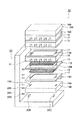
図1に示すように、燃料電池10は、複数の発電セル12を積み重ねて直列に接続したセルスタック10Sを備える。発電セル12は、燃料極集電体17と酸素極集電体16とに挟み込んで積み重ねられ、圧板19A、19Bを用いて全体を積み重ね方向に加圧して組み立てられている。
As shown in FIG. 1, the
発電セル12は、膜電極接合体12Mの一方の面に燃料拡散電極15、他方の面に酸素拡散電極14を接触させている。膜電極接合体12Mは、高分子電解質膜の両面に触媒層を形成してある。燃料拡散電極15に接する触媒層では、水素ガスが触媒反応によって水素原子に分解されてイオン化し、水素イオンが高分子電解質膜に供給される。酸素拡散電極14に接する触媒層では、触媒反応によって酸素が、発電セル12の起電力に打ち勝って高分子電解質膜から拾い上げた水素イオンに化合して水分子を生成する。高分子電解質膜は、燃料拡散電極15側から酸素拡散電極14側へ水素イオンを移動させる。
In the
発電セル12の高分子電解質膜には、デュポン社製のNafion112(商標)膜を使用した。また、触媒層を形成するための触媒粉末として、ジョンソン&マッセイ社のHiSPEC1000(商標)を使用し、電解質溶液としてはデュポン社のNafion(商標)溶液を使用した。
A Nafion 112 (trademark) membrane manufactured by DuPont was used as the polymer electrolyte membrane of the
触媒粉末と電解質溶液との混合分散液を作製してドクターブレード法を用いてフッ素樹脂(PTFE)シート上に成膜し、触媒シートとした。次に、作製した触媒シートをデカール法によって、150度C、10MPa(100kgf/cm2)で高分子電解質膜上にホットプレス転写して膜電極接合体12Mを製作した。
A mixed dispersion of the catalyst powder and the electrolyte solution was prepared and formed on a fluororesin (PTFE) sheet using a doctor blade method to obtain a catalyst sheet. Next, the produced catalyst sheet was hot-press transferred onto a polymer electrolyte membrane at 150 ° C. and 10 MPa (100 kgf / cm 2 ) by a decal method to produce a
燃料拡散電極15は、燃料極集電体17に形成された凹所に配置され、セルスタック10Sを貫通する燃料主流路13Aに連通している。燃料拡散電極15の外周は密封されているので、水素ガスが大気中および酸素拡散電極14へ漏れ出さない。酸素拡散電極14は、酸素極集電体16に形成された凹所に格納され、酸素極集電体16の空気取り入れ口11を通じて側面の一部が大気に開放されている。
The
燃料拡散電極15および酸素拡散電極14には導電性のあるカーボンクロス電極(E−TEK社製)を採用した。上述のように製作した膜電極接合体12Mを燃料拡散電極15および酸素拡散電極14で挟持し、その外側を燃料極集電体17および酸素極集電体16で挟んでセルスタック10Sの各段を製作した。各段を積み重ねて圧板19A、19Bで締結して燃料電池10を組み立てた。
As the
各段の酸素極集電体16、発電セル12(膜電極接合体12M)、燃料極集電体17、および圧板19Aには、平面位置を合わせて燃料主流路13Aおよび給水主流路13Bの貫通孔が形成されている。圧板19Aの下面に位置する燃料主流路13Aの末端には、燃料主流路13Aの気密性を保って管路の接続/切り離しが可能な接続ポートが配置されている。このような接続ポートは、コネクタとプラグとの接続によって双方の封止用のボールが移動してそれぞれ隙間を形成するフィッティングコネクタとしてもよい。燃料主流路13Aの接続ポートには、通常、水素吸蔵合金を用いて水素ガスを高圧貯蔵する燃料タンク(不図示)が接続されている。
The oxygen electrode
活性化装置20は、不図示の位置決め機構に案内させて、燃料電池10を上方から装着することにより、燃料電池10を保持機構20Aに位置決め保持する。保持機構20Aの床面には、燃料主流路13A、および給水主流路13Bの接続ポートに対してそれぞれ着脱可能で、燃料電池10の装着と同時に接続される燃料供給コネクタ20Bと給水コネクタ20Cとが配置される。また、保持機構20Aの起立面には、燃料電池10の装着と同時に各段の燃料極集電体17と酸素極集電体16とにそれぞれ接触して電流を取り出し可能となる接続電極20D、20Eが配置される。
The
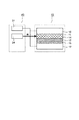
燃料電池10は、図2に示すように、模式的に図示される。図2に示すように、燃料タンク10Gを燃料電池10に接続し、大気圧よりも少し高い圧力に調圧された水素ガスを、燃料主流路13Aを通じて燃料拡散電極15に供給する。大気中の酸素は、空気取り入れ口11から取り込ませて、自然拡散によって酸素拡散電極14に供給する。このような通常の運転状態で、酸素極集電体16と燃料極集電体17とを定電圧負荷21に接続して、発電を開始させた。水素および空気は、無加湿状態で供給され、室温は25℃、相対湿度は50%であった。
The
初期状態の発電特性と5分間発電後の発電特性との比較を図3に示す。5分間の発電は、セル電圧を0.6Vに保って行った。図3に示すように、5分間の運転によって燃料電池10の起電力が上昇し、0.6V出力での電流値は2倍近くに達している。以下に説明する各種の活性化処理に対し、本発電を「通常発電」とし、比較例として用いる。
FIG. 3 shows a comparison between the power generation characteristics in the initial state and the power generation characteristics after 5 minutes of power generation. The power generation for 5 minutes was performed with the cell voltage maintained at 0.6V. As shown in FIG. 3, the electromotive force of the
図4に示すように、活性化装置20は、定電圧負荷21と運転補助機構30とを備える。定電圧負荷21は、定電圧負荷21の端子電圧を検知して端子電圧を一定に保つように消費電力を刻々と変化させる電子負荷である。定電圧負荷21は、例えば、ヒートシンクに取り付けたパワートランジスタのベース電圧をツェナーダイオードの定電圧で制御する一般的な定電圧回路で実現される。
As shown in FIG. 4, the
活性化装置20は、燃料供給コネクタ20Bから燃料主流路13Aを通じて燃料電池10に水素ガスを供給する。活性化装置20に内蔵された不図示の燃料タンクから取り出された水素ガスは、通常の運転状態と同じ圧力に調圧され、加湿器22(図5)を用いて加湿される。
The
活性化装置20は、不図示の水タンクとポンプとを内蔵している。水タンクから取り出した水をポンプで送り出し、給水コネクタ20Cから給水主流路13Bを通じて燃料電池10の酸素拡散電極14に注水して、発電セル12の酸素供給側に給水可能である。
The
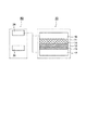
図5に示すように、活性化装置20は、運転補助機構30として、水素ガスの加湿器22を備えている。加湿器22は、水素ガスの供給系に配置された外部から給水可能な保水空間と、保水空間の外側に配置したヒータとを有しており、ヒータに通電して保水空間の水を水蒸気化することにより、保水空間を通過する水素ガスを加湿する。
As shown in FIG. 5, the
水素ガスを加湿して燃料拡散電極15に供給しながら定電圧負荷21を作動させた。図6に示すように、セル電圧を0.6Vに保ち、5分間発電を行った後の発電特性を測定したところ、加湿を伴わない通常発電の場合よりも速やかな特性向上が見られた。
The
図7に示すように、活性化装置20は、運転補助機構30として、酸素拡散電極14に水を注入して発電セル12の酸素供給側に給水する給水器23を備えている。酸素拡散電極14に水を注入して発電セル12の酸素供給側へ拡散させた後に定電圧負荷21を作動させた。図8に示すように、セル電圧を0.6Vに保ち、5分間発電を行った後の発電特性を測定したところ、給水を伴わない通常発電の場合よりも速やかな特性向上が見られた。
As shown in FIG. 7, the
加湿器22を用いて水素ガスの加湿を行った場合と、給水器23を用いて発電セル12に給水した場合とで、定電圧負荷21に取り出された電流値の変化、すなわち発電性能の回復過程を比較した。図9に示すように、加湿の場合は、発電開始直後から通常発電に比較して大きな電流を電流を取り出せるが、給水の場合は次第に大きな電流を取り出せる。しかし、いずれの場合でも、通常発電に比較して速やかで高い特性回復、すなわち、5分程度を要する通常発電に対して、1分以下で通常発電以上の特性回復が得られた。
Changes in the current value taken out to the
また、発電後の燃料電池10の内部抵抗の変化を比較すると、初期状態で8Ω程度だった抵抗が、通常発電後には0.6Ω程度まで下がったのに対し、給水を行った場合には0.3Ω、加湿を行った場合には0.2Ωにまで大きく下げることができた。燃料電池10(発電セル12)の初期状態からの定電圧発電における電流値の変化の様子は図9に示すとおりである。活性化装置20に燃料電池10を装着して、加湿と給水との少なくとも一方、好ましくは両方を行うことで、通常発電を行う場合よりもはるかに短時間で、はるかに高い発電性能への回復が実現される。電流値の向上が大きく見られる。
In addition, when the change in the internal resistance of the
発電セル12の膜電極接合体12Mの水素供給側は、密封空間で外部からの給水が困難で、酸素供給側で生成された水分子が濃度拡散するのを待って湿潤してイオン伝導性が回復する。加湿の場合は、このような時間のかかる濃度拡散を待たずに膜電極接合体12Mの水素供給側に直接水分補給できるため、発電開始の直後から通常発電に比較して大きな電流を電流を取り出せる。給水の場合は、発電による水分子の生成を待たずに膜電極接合体12Mの膜厚方向の濃度拡散が促進されるため、次第に大きな電流を取り出せる。
The hydrogen supply side of the
尚、水素ガスではなく、大気を加湿した場合にも同様の結果が得られる。大気の加湿は、燃料電池を、所定の温湿度状態に保った恒温恒湿槽中に設置して運転を行うことで、実現できる。 Similar results can be obtained when the atmosphere is humidified instead of hydrogen gas. Humidification of the atmosphere can be realized by installing the fuel cell in a constant temperature and humidity chamber maintained in a predetermined temperature and humidity state and operating.
<第2実施形態>
図10はヒータ加熱を行う活性化装置の構成の説明図、図11は第2実施形態の活性化装置の構成の説明図である。第2実施形態の活性化装置40は、加湿を伴ってヒータ加熱を行う以外は第1実施形態と同様に構成される。従って、図1〜図9を併せて参照して説明を行い、図4、図5と共通する構成には共通の符号を付して詳細な説明を省略する。
Second Embodiment
FIG. 10 is an explanatory diagram of the configuration of the activation device that performs heater heating, and FIG. 11 is an explanatory diagram of the configuration of the activation device of the second embodiment. The
運転補助機構30(図4)として、図10に示すように、ヒータ24を用い、燃料電池10を加熱した状態で定電圧負荷21を作動させて発電を行わせた場合、通常発電の場合に比較した電流値の低下、および、発電セル12の内部抵抗の増加が見られた。これは、加熱によって水分がさらに失われて膜電極接合体12Mが乾燥し、高分子電解質膜のイオン伝導度が低下してしまったためと考えられる。
As the driving assist mechanism 30 (FIG. 4), as shown in FIG. 10, when the
図11に示すように、第2実施形態の活性化装置40では、運転補助機構30(図4)として、ヒータ24と加湿器22とを搭載している。ヒータ24は、図1に示す燃料電池10の外周を筒状に囲んで保持機構20Aに配置され、商用電源を用いて通電されることにより、セルスタック10Sを外側から強制的に80度Cまで加熱する。
As shown in FIG. 11, in the
第1実施形態と同様に加湿器22による水素ガスの加湿供給と並行してヒータ24による加熱を行いつつ、定電圧負荷21を作動させて発電を開始させたところ、図6、図9に示すよりも起動特性の向上が見られた。すなわち、0.6V出力における電流値が発電開始直後から上昇して、水生成量が増し、加熱に打ち勝って膜電極接合体12Mの湿潤度の回復が早められた。
As in the first embodiment, the power generation is started by operating the
<第3実施形態>
図12は第3実施形態の活性化装置の構成の説明図、図13はブロワーを用いた場合と用いなかった場合とで発電性能を比較した線図である。第3実施形態の活性化装置50は、ブロワー25を用いて活性化を行う以外は第1実施形態と同様に構成される。従って、図1〜図9を併せて参照して説明を行い、図4、図5と共通する構成には共通の符号を付して詳細な説明を省略する。
<Third Embodiment>
FIG. 12 is an explanatory diagram of the configuration of the activation device according to the third embodiment, and FIG. 13 is a diagram comparing the power generation performance with and without the use of the blower. The activation device 50 of the third embodiment is configured in the same manner as in the first embodiment except that activation is performed using the blower 25. Therefore, the description will be made with reference to FIGS. 1 to 9, and the same reference numerals are given to the components common to FIGS. 4 and 5, and the detailed description will be omitted.
図12に示すように、第3実施形態の活性化装置50では、運転補助機構30(図4)として、ブロワー25を設けた。ブロワー25は、図1に示すセルスタック10Sの空気取り入れ口11に対向させて保持機構20Aに配置され、セルスタック10Sを貫通する空気取り入れ口11に強制的に大気を送り込む。これにより、発電開始後も空気取り入れ口11の空間内の酸素濃度が高く維持されて酸素拡散電極14に対する酸素供給量が増大する。
As shown in FIG. 12, in the activation apparatus 50 of 3rd Embodiment, the blower 25 was provided as the driving assistance mechanism 30 (FIG. 4). The blower 25 is disposed in the
活性化装置50のブロワー25を作動させた状態で定電圧負荷21を作動させて発電を開始させたところ、図13に示すように、ブロワーを用いなかった場合に比べて、最大電流が30%向上した。これにより、燃料電池10の活性化を行う際の電流量を大きくすることができ、水生成を促進して膜電極接合体12Mの湿潤度を速やかに高め、活性化時間を早めることができた。
When the
特に、定格電流の小さな燃料電池10においては、定格電流では、活性化処理が困難であったのに対し、ブロワー25によって、活性化に十分な電流を流せるようになるとともに、活性化時間を短縮することができた。
In particular, in the
なお、図12に示すブロワー25は、コンプレッサを使用した空気の吹き付けに置き換えてもよい。空気取り入れ口11を通じた酸素の拡散と余分な水蒸気の排出とを促進する機能において等しく、同様に速やかな活性化の効果が得られる。
The blower 25 shown in FIG. 12 may be replaced with air blowing using a compressor. Equally in the function of promoting the diffusion of oxygen through the
<第4実施形態>
図14は第4実施形態の活性化装置の構成の説明図、図15は運転補助機構として直流電源と給水器とを併用した構成の説明図、図16は直流電源と給水器とを併用した活性化効果を説明する線図である。第4実施形態の活性化装置60は、直流電源26を用いて発電セル12から出力される電流を強制的に高める以外は第1実施形態と同様に構成される。従って、図1〜図9を併せて参照して説明を行い、図4、図5と共通する構成には共通の符号を付して詳細な説明を省略する。
<Fourth embodiment>
FIG. 14 is an explanatory diagram of the configuration of the activation device of the fourth embodiment, FIG. 15 is an explanatory diagram of a configuration in which a DC power source and a water feeder are used together as an operation assisting mechanism, and FIG. 16 is a combination of a DC power source and a water feeder. It is a diagram explaining the activation effect. The
図14に示すように、第4実施形態の活性化装置60は、発電セル12の両極間に起電力と逆極性の電圧を印加して、水生成量を意図的に高めることにより、発電セル12の活性化処理を行う。すなわち、膜電極接合体12Mの燃料拡散電極15側に+の電圧を印加し、酸素拡散電極14側に−の電圧を印加する。これにより、膜電極接合体12Mの燃料拡散電極15側と酸素拡散電極14側とを短絡させた以上の電流を強制的に流して膜電極接合体12Mの酸素拡散電極14での水生成量を急速に増加させる。
As shown in FIG. 14, the
燃料電池10は、第1実施形態と同様に作製した。活性化装置60は、直流電源26と運転補助機構30とを有する。直流電源26は、商用電源を用いて作動する定電流電源であって、限界電圧と出力電流とを設定できる。直流電源26は、設定された限界電圧を上回らない範囲で出力電圧を変化させて出力電流を設定された値に維持する。
The
図15に示すように、運転補助機構30は、第1実施形態と同じ給水器23である。給水器23は、活性化装置60に内蔵された不図示の水タンクから取り出した水を、活性化装置60に内蔵された不図示のポンプで押し出して給水主流路13Bに送り込む(図1参照)。給水主流路13Bを通じて酸素拡散電極14に注水された水は、膜電極接合体12Mの酸素拡散電極14側を濡らして膜電極接合体12Mを湿潤させる。
As shown in FIG. 15, the driving
燃料電池10を活性化装置60の保持機構20Aにセットして(図1参照)、接続電極20D、20Eに接続された直流電源26により、酸素拡散電極14を陰極とし、燃料拡散電極15を陽極として直流電圧を2分間印加した。
The
発電セル12に給水しつつ定電圧負荷を接続して活性化させた場合(第1実施形態)と、発電セル12に給水しつつ強制的に定電流を流して活性化させた場合との比較結果を図16に示す。定電流値を0.5Aに設定した場合と1.0Aに設定した場合とが活性化後の電圧−電流特性で示される。直流電圧を印加して定電流を流すことで、湿潤度の低い初期状態でも大量の水を生成させて、膜電極接合体12Mの湿潤度を急速に高めることができ、発電特性が大きく向上している。
Comparison between the case where the constant voltage load is connected and activated while supplying water to the power generation cell 12 (first embodiment) and the case where the constant current is forced to flow while supplying water to the
なお、給水器23を用いて発電セル12に水を注入するかわりに、加湿器22を用いて水素ガスを加湿しても、直流電源26と併用することにより第1実施形態よりも速やかな発電特性の向上が見られた。
Instead of injecting water into the
また、給水器23は、活性化装置60に内蔵された不図示の水タンクから取り出した水を加熱し、水蒸気化して給水主流路13Bに送り込む(図1参照)水蒸気供給装置に置き換えてもよい。活性化装置60にポンプを不要にでき、膜電極接合体12Mの加湿と加熱とを同時に達成して、直流電源26は、より低い電圧で同じ定電流を実現できる。液体水が膜電極接合体12Mの表面を覆って酸素の拡散を阻害することが無いので、直流電源26は、給水器23よりも確実に定電流を実現できる。
Further, the
また、第2実施形態と同様にセルスタック10Sを外部から加熱するヒータ24を併用しても、直流電源26によって直流電圧を印加することで、さらなる活性化を行うことができる。
Further, even when the
一方、燃料電池10の初期状態(乾燥状態)に、加湿や給水を伴わないで直流電源26を接続して同様に定電流を流した場合、発電セル12の内部抵抗が増大して、かえって発電特性が低下した。これは、電圧印加に伴う発熱で膜電極接合体12Mの材料中の水分が蒸発して、高分子電解質膜がさらに乾燥状態となり、イオン伝導度が低下したためと考えられる。
On the other hand, when the
<第5実施形態>
図17はセルスタックの発電セルにおける転極現象の説明図である。図中、(a)は正常な発電状態、(b)は転極が発生した状態である。
<Fifth Embodiment>
FIG. 17 is an explanatory diagram of the inversion phenomenon in the power generation cell of the cell stack. In the figure, (a) shows a normal power generation state, and (b) shows a state where inversion has occurred.
図17の(a)に示すように、複数の発電セル12を直列に接続したセルスタック10Sでの発電においては、大電流を流した際に、そのうちの1つの発電セル12の電圧が大幅に低下し、さらには、図17の(b)に示すように、1つの発電セル12に逆の電圧がかかる現象が見られる。
As shown in FIG. 17A, in the power generation in the
この現象は、以下のように説明される。図17の(a)に示すように、6段の発電セル12を積層した燃料電池を考える。定電圧負荷21をセルスタック10Sの出力電圧が3.0Vになるように調節すると、発電セル12にばらつきがなければ、各段の発電セル12の電圧は全て0.5Vとなる。
This phenomenon is explained as follows. Consider a fuel cell in which six-stage
しかし、各段の発電セル12の状態にばらつきがあると、図17の(b)に示すように、特性の悪い発電セル12に大きな負荷がかかり、場合によっては、他の発電セル12によって逆起電力が印加される。この現象は転極と呼ばれる。
However, if there are variations in the state of the
従って、機器に燃料電池10を装填して電力を取り出すセルスタック10Sの通常発電では、安全率を高く確保して、単独の発電セル12の状態よりもさらに小さな電流しか取り出させない。特に、大気中の酸素を自然拡散によって発電セル12に取り入れる条件下や、水素ガスの加湿を行わない条件下では、酸素供給不足や膜電極接合体12Mの乾燥によるイオン伝導度の低下により、転極が起こり易い。
Therefore, in the normal power generation of the
しかし、第1実施形態〜第4実施形態では、環境条件が不定な機器から燃料電池10を取り出して、環境条件を一定に確保した単独の活性化装置20、40、50、60に装着し、加湿器22、給水器23、ヒータ24、ブロワー25等を用いる。これにより、発電セル12が転極するのを避けて、安定した活性化処理を行うことができる。
However, in the first to fourth embodiments, the
運転補助機構30は、図1に示すように、各段の燃料極集電体17と酸素極集電体16とに対応させた接続電極20D、20Eを用いて、各段の発電セル12ごとに燃料電池10の発電性能を回復させている。しかし、第1実施形態〜第4実施形態の運転補助機構30は、セルスタック10Sから電力を取り出す取り出し電極18A、18bを用いて定電圧負荷21や直流電源26を接続し、セルスタック10Sを構成する複数の発電セル12を一体に活性化させてもよい。
As shown in FIG. 1, the driving
活性化装置20、40、50、60では、セルスタック10Sの各段の発電セル12に対して酸素がほぼ均等に供給される。このため、発電セル12では、酸素供給に起因した異常な分極現象が発生しにくい。
In the
従って、膜電極接合体12Mの湿潤状態を保つことさえできれば、取り出し電極18A、18bを用いて定電圧負荷21や直流電源26を接続した際に、図17の(b)に示すような転極が発生しない。転極により燃料電池セルが劣化してしまう現象も起こりにくい。
Therefore, as long as the
また、活性化処理中の燃料拡散電極15および酸素拡散電極14中の雰囲気は、燃料電池10の通常運転における発電状態のまま、それぞれ、水素、および空気(あるいは酸素)としても良いし、窒素などの不活性ガス雰囲気としても良い。また、燃料主流路13Aは出口を閉じた状態としておいても、開いた状態としておいても良い。
Further, the atmosphere in the
また、第1実施形態〜第4実施形態で説明した運転補助機構30は、複数の発電セル12を直列に接続したセルスタック10Sを備えた燃料電池10のみならず、発電セル12を単独で扱う燃料電池に対しても有効である。
Further, the driving
また、小型燃料電池は、燃料供給路の出口を塞ぎ、消費された量の燃料のみを供給する場合が多いが、本発明の活性化方法は、燃料流路の出口を所定量開き、燃料を消費量以上供給した状態で行うことが好ましい。 In addition, the small fuel cell often closes the outlet of the fuel supply path and supplies only the consumed amount of fuel. However, the activation method of the present invention opens the outlet of the fuel flow path by a predetermined amount and supplies the fuel. It is preferable to carry out in a state where more than the consumption is supplied.
<第6実施形態>
図18は第6実施形態の活性化装置に装着される燃料電池の構成の説明図、図19は第6実施形態の活性化装置の構成の説明図である。第1実施形態〜第5実施形態の活性化装置は、複数の発電セルを積み重ねて直列に接続した燃料電池の活性化を説明した。これに対して第6実施形態の活性化装置70は、発電セル112を平面的に複数配置した燃料電池110を装着して活性化を行って起動時の発電性能を改善する。
<Sixth Embodiment>
FIG. 18 is an explanatory diagram of the configuration of the fuel cell mounted on the activation device of the sixth embodiment, and FIG. 19 is an explanatory diagram of the configuration of the activation device of the sixth embodiment. The activation apparatus of 1st Embodiment-5th Embodiment demonstrated activation of the fuel cell which piled up several power generation cells and connected in series. On the other hand, the
図18に示すように、平面的に配列された複数の発電セル112は、共通の燃料極集電体117と酸素極集電体116とによって並列に接続されて並列に電力を取り出される。発電セル112は、膜電極接合体112Mの一方の面に燃料拡散電極115、他方の面に酸素拡散電極114を接触させている。膜電極接合体112Mは、高分子電解質膜の両面に触媒層を形成してある。
As shown in FIG. 18, the plurality of
燃料拡散電極115、酸素拡散電極114は、それぞれ燃料極スペーサ103、酸素極スペーサ104の独立した開口に収められている。燃料極スペーサ103、酸素極スペーサ104は、発電セル112とともに、燃料極集電体117と酸素極集電体116との間隔に挟み込んで組み立てられる。
The
燃料極集電体117、酸素極集電体116は、導電性の多孔性材料を発電セル112ごとに独立して配置しており、隣接する発電セル112間で水素ガス、酸素がそれぞれ拡散しないようにしてある。発電セル112への水素ガスの供給は、燃料極集電体117の下面に配置された流路基板102を通じて行われる。燃料極集電体117および燃料極スペーサ103の仕切り枠と、膜電極接続体112Mと、流路基板102とで囲まれた空間は、燃料極拡散電極115を収納して外気から密封された燃料空間となっている。
In the fuel electrode
酸素拡散電極114は、酸素極スペーサ104の仕切り枠に格納されて酸素極集電体116を通じて表面が大気に開放されている。燃料電池110は、発電セル112を平面的に配列しているので、図1に示すセルスタック10Sに積み重ねた形式に比較して、酸素の取り入れ面積、水蒸気の排出面積を広く確保できる。
The
流路基板102には、複数の発電セル112へ水素ガスを分配する流路106が形成されている。燃料極集電体117に接する部分の流路106は、浅く形成して流路抵抗を高めてあるので、水素ガスが素通りしない。流路106には、不図示の燃料タンクから取り出して大気圧より少しだけ高い圧力に調圧された水素ガスが供給され、流路1−6から燃料極集電体117を通じて燃料拡散電極115へ流れ込む。
A
燃料拡散電極115に接する膜電極接合体112Mの触媒層では、水素ガスが触媒反応によって水素原子に分解されてイオン化し、水素イオンが高分子電解質膜に供給される。酸素拡散電極114に接する膜電極接合体112Mの触媒層では、触媒反応によって酸素が高分子電解質膜から拾い上げた水素イオンに化合して水分子を生成する。膜電極接合体112Mの高分子電解質膜は、燃料拡散電極115側から酸素拡散電極114側へ水素イオンを移動させる。
In the catalyst layer of the membrane electrode assembly 112M in contact with the
図19に示すように、第6実施形態の活性化装置70は、本体70Aの上面に形成された凹所に燃料電池110を嵌め込み、押さえ板70Bで燃料電池110を本体70Aに押え付けて固定する。固定と同時に、燃料電池110の流路106が本体70A側の水素ガス供給部に位置決め接続され、取り出し電極118A、118Bが定電圧負荷21に接続される。
As shown in FIG. 19, in the
本体70A側の水素ガス供給部には、水素ガスを貯蔵する燃料タンク71から取り出した水素ガスが保水空間72を通じて供給される。保水空間72は、外部から給水可能な密封空間で外側にヒータ73を備えている。保水空間72に給水した水をヒータ73で加熱蒸発させて水素ガスが加湿される。
The hydrogen gas taken out from the
第1実施形態と同様に、燃料電池110を活性化装置70に装着して、加湿した水素ガスを供給しつつ定電圧負荷21を作動させる。そして、機器に装着して取り出される通常の電流よりもはるかに大きな電流を短時間(1分間以内)強制的に出力させることにより、乾燥した初期状態の膜電極接合体112Mの湿潤度を急速に高める。これにより、燃料電池110の発電性能が速やかに回復して、活性化装置70から取り出して機器に装着すると、直ちに高い起電力で大きな電流を出力できる。
As in the first embodiment, the
<第7実施形態>
第1実施形態〜第6実施形態では、機器へ装着する前の燃料電池10、110を単独の活性化装置20、40、50、60、70に装着して活性化している。しかし、燃料電池10、110の製作過程で、燃料電池10、110を組み立てた後に、活性化装置20、40、50、60、70に装着して、低格電流よりもはるかに大きな電流を短時間強制的に出力させて、燃料電池10、110の発電性能を高めてもよい。その後、燃料電池10、110を水蒸気パックすることで、パックから取り出して機器に装着された燃料電池10、110は、直ちに高い起電力で大きな電流を出力できる。
<Seventh embodiment>
In the first to sixth embodiments, the
<比較例の活性化装置>
従来、小型の電気機器を持ち運んで使用するためには、種々の一次電池、二次電池が使用されてきた。しかし、最近の小型電気機器の高性能化に伴い、消費電力が大きくなり、一次電池では、小型軽量で、十分なエネルギーを供給できなくなっている。一方、二次電池においては、繰り返し充電して使用できるという利点はあるものの、一回の充電で使用できるエネルギーは一次電池よりも更に少ない。そして、二次電池の充電の為には、別の電源が必要である上、充電には、通常、数十分から数時間かかり、いつでもどこでもすぐに使用できる様にするということは困難である。今後、電気機器のますますの小型、軽量化が進み、ワイヤレスのネットワーク環境が整うことにより、機器を持ち運んで使用する傾向が高まる中で、従来の一次電池、二次電池では機器の駆動に十分なエネルギーを供給することは困難である。
<Activation device of comparative example>
Conventionally, various primary batteries and secondary batteries have been used to carry and use small electric devices. However, with recent high performance of small electric devices, power consumption has increased, and primary batteries are small and light and cannot supply sufficient energy. On the other hand, although the secondary battery has an advantage that it can be repeatedly charged and used, the energy that can be used in one charge is much less than that of the primary battery. In order to charge the secondary battery, a separate power source is required, and charging usually takes several tens of minutes to several hours, and it is difficult to immediately use it anytime and anywhere. . In the future, as electric devices become increasingly smaller and lighter, and the wireless network environment is in place, the tendency to carry and use devices will increase. Conventional primary and secondary batteries are sufficient to drive devices. It is difficult to supply a large amount of energy.
このような問題の解決策として、小型の燃料電池が注目されている。燃料電池は従来、大型の発電機、自動車用の駆動源として開発が進められてきた。これは、燃料電池が、従来の発電システムに比べて、発電効率が高く、しかも廃棄物がクリーンであることが主な理由である。一方、燃料電池が小型電気機器の駆動源として有用な理由に体積当たり、重量当たりの供給可能なエネルギー量が従来の電池に比べて、数倍から十倍近くであることが挙げられる。さらに、燃料のみを交換すれば連続して使用が可能であるため、他の二次電池の様に充電に時間がかかることもない。 As a solution to such a problem, a small fuel cell has attracted attention. Conventionally, fuel cells have been developed as a drive source for large generators and automobiles. This is mainly because the fuel cell has higher power generation efficiency and clean waste than the conventional power generation system. On the other hand, the reason why fuel cells are useful as a drive source for small electric devices is that the amount of energy that can be supplied per volume and per weight is several to ten times that of conventional batteries. Furthermore, since it can be used continuously if only the fuel is replaced, it does not take time to charge unlike other secondary batteries.
燃料電池には、様々な方式のものが発明されているが、小型電気機器、とりわけ持ち運びして使用する機器に対しては、高分子電解質膜を用いた燃料電池が適している。これは、常温に近い温度で使用でき、また、電解質が液体ではなく固体であるので、安全に持ち運べるという利点を有しているためである。 Although various types of fuel cells have been invented, a fuel cell using a polymer electrolyte membrane is suitable for small electric devices, particularly devices that are carried and used. This is because it can be used at a temperature close to room temperature, and since the electrolyte is a solid rather than a liquid, it has the advantage of being safe to carry.
高分子電解質膜を用いた燃料電池の発電の反応場である膜電極接合体は、高分子電解質膜の両面に触媒層を配置した構造を有する。触媒層は、触媒および電解質の混合物からなる。さらに、触媒層には、撥水性や導電性を付与するために、種々の物質を添加する場合もある。膜電極接合体を多孔質電極で挟持して発電セルとする。発電セルは、燃料拡散電極に燃料(水素)、酸素拡散電極に酸化剤(酸素または空気)を供給することより、触媒反応が起こり、発電する。その際、生成物として水が発生する。燃料拡散電極、および、酸素拡散電極での反応式は、以下の通りである。 A membrane electrode assembly, which is a reaction field for power generation of a fuel cell using a polymer electrolyte membrane, has a structure in which catalyst layers are arranged on both sides of the polymer electrolyte membrane. The catalyst layer is composed of a mixture of a catalyst and an electrolyte. Further, various substances may be added to the catalyst layer in order to impart water repellency and conductivity. The membrane electrode assembly is sandwiched between porous electrodes to form a power generation cell. In the power generation cell, a fuel (hydrogen) is supplied to the fuel diffusion electrode and an oxidizing agent (oxygen or air) is supplied to the oxygen diffusion electrode. At that time, water is generated as a product. The reaction formulas at the fuel diffusion electrode and the oxygen diffusion electrode are as follows.
燃料拡散電極

酸素拡散電極
燃料拡散電極で生成したプロトンは高分子電解質膜中を通って酸素拡散電極に伝わり、酸素拡散電極側の触媒層で酸素および電子と反応して水が生成する。プロトンは高分子電解質膜、燃料拡散電極、および酸素拡散電極の電解質中の水で満たされたクラスター部分を通って移動する。そのため、発電に際しては、高分子電解質膜、燃料拡散電極、および酸素拡散電極の電解質が十分に含水している必要がある。これにより、イオン伝導抵抗が低減され、また、触媒表面にプロトンが到達しやすくなることで事実上の反応サイトが多くなり、燃料電池の出力特性が向上する。 Protons generated at the fuel diffusion electrode pass through the polymer electrolyte membrane to the oxygen diffusion electrode, and react with oxygen and electrons in the catalyst layer on the oxygen diffusion electrode side to generate water. Protons travel through cluster portions filled with water in the electrolyte of the polymer electrolyte membrane, the fuel diffusion electrode, and the oxygen diffusion electrode. Therefore, at the time of power generation, the electrolyte of the polymer electrolyte membrane, the fuel diffusion electrode, and the oxygen diffusion electrode needs to be sufficiently hydrated. As a result, the ion conduction resistance is reduced, and protons easily reach the catalyst surface, thereby increasing the number of reaction sites in effect and improving the output characteristics of the fuel cell.
特に、作製後、未発電の膜電極接合体は、作製プロセスにより、含水率が低下している場合が多い。また、プロトンを伝導するクラスター形状も最適化されていない。このような低活性状態の膜電極接合体は、一定量以上の電流を流した発電を行うことで、電解質膜が含水し、また、クラスター構造の最適化が行なわれ、活性化される。固体高分子形燃料電池の反応は80℃程度で特に活性化される。 In particular, after production, a membrane electrode assembly that has not yet generated electricity often has a reduced moisture content due to the production process. In addition, the shape of the cluster that conducts protons is not optimized. Such a membrane electrode assembly in a low activity state is activated by generating power with a current of a certain amount or more, so that the electrolyte membrane contains water and the cluster structure is optimized. The reaction of the polymer electrolyte fuel cell is particularly activated at about 80 ° C.
そこで、特許文献1においては、固体高分子形燃料電池を発電状態にする前にコンディショニングすることにより、高い電池出力で迅速に起動することができる燃料電池の起動方法および製造方法を開示している。コンディショニングとは、燃料電池を外部回路に接続し、燃料電池および外部回路に、発電時において外部負荷要求に基づき要求される所定の出力電流密度の設定値よりも高い電流密度の電流を予め流すことである。
Therefore,
また、特許文献2においては、燃料電池の起動時において、燃料電池の出力電圧を検出し、十分な出力電圧が得られておらず、燃料電池が定格運転状態でないと判断すると、燃料電池の両極への接続を外部出力からインピーダンスに切り替える。これにより、発電によって燃料電池が加熱され、定格運転可能状態へと移行する方法を開示している。
Further, in
燃料電池を高出力で運転する方法として、空気をブロワーなどにより、強制的に供給する方法がある。例えば、特許文献3においては、燃料電池の定格発電時に空気を燃料電池セルに強制的に供給する手段を開示する。また、特許文献4においては送風機構を燃料電池本体ではなく、燃料電池を搭載する機器内に備えた燃料電池システムを開示している。 As a method of operating the fuel cell at a high output, there is a method of forcibly supplying air by a blower or the like. For example, Patent Document 3 discloses means for forcibly supplying air to a fuel cell at the time of rated power generation of the fuel cell. Further, Patent Document 4 discloses a fuel cell system in which a blower mechanism is provided not in the fuel cell body but in a device in which the fuel cell is mounted.
ところで、発電セルに水が供給された状態で、両極間に電圧を印加すると、燃料電池と逆の反応によって、水の電気分解が起こる。すなわち陽極、陰極間の通電により、陰極の触媒層で、酸素が発生し、陽極の触媒層で水素が発生する。高分子電解質膜を用いた水の電気分解は、エネルギー効率が90%と高く、また、電流密度が1〜3A/cm2と高いため、コンパクトで高効率な水素生成装置として実用化されている。さらに、高分子電解質膜は、固体であり、また反応温度が数十℃であることから、手軽で安全であるという利点も有している。 By the way, when a voltage is applied between both electrodes in a state where water is supplied to the power generation cell, electrolysis of water occurs due to a reaction opposite to that of the fuel cell. That is, when electricity is applied between the anode and the cathode, oxygen is generated in the cathode catalyst layer, and hydrogen is generated in the anode catalyst layer. Water electrolysis using a polymer electrolyte membrane has a high energy efficiency of 90% and a high current density of 1 to 3 A / cm 2 , so it has been put to practical use as a compact and highly efficient hydrogen generator. . Furthermore, since the polymer electrolyte membrane is solid and the reaction temperature is several tens of degrees Celsius, it has the advantage of being easy and safe.
しかし、小型電気機器に搭載される燃料電池は、システムの小型化のため、加湿器やヒータ、ポンプやブロワーなどを用いない場合が多い。このような燃料電池では、加湿は発電の際に生成する水により、加熱は発電熱によって行なわれる。また、反応に必要な空気は自然拡散によって取り入れられる。このような燃料電池に対して、従来の活性化・起動方法を用いても、取り入れられる燃料や空気の量に限界があり、また、初期の電解質の抵抗が大きいため、運転温度や電解質の含水状態を最適な状態にまで高めるのに十分な出力を得ることは難しかった。 However, in many cases, a fuel cell mounted on a small electric device does not use a humidifier, a heater, a pump, a blower, or the like in order to reduce the size of the system. In such a fuel cell, humidification is performed by water generated during power generation, and heating is performed by generated heat. The air necessary for the reaction is taken in by natural diffusion. Even if conventional activation / startup methods are used for such fuel cells, the amount of fuel and air that can be taken in is limited, and the resistance of the initial electrolyte is large, so the operating temperature and water content of the electrolyte It was difficult to obtain sufficient output to raise the state to the optimum state.
特に、複数の発電セルを直列に接続して用いる場合においては、燃料電池の発電性能限界に近い状態での運転は、1組の燃料電池セルに他の燃料電池セルの電圧が強制的に印加される転極現象が起きる。転極現象が起きると、システムが非常に不安定な状態になるとともに、燃料電池の劣化を引き起こす恐れがあった。また、小型電気機器用の燃料電池においても、ブロワーなどを搭載する場合もあったが、これは、定格出力時に出力を高めるために使用され、燃料電池の使用中に取り外すことはできなかった。このようなポンプやブロワ−は、使用時のシステムの大型化を招く恐れがあった。 In particular, in the case of using a plurality of power generation cells connected in series, operation in a state close to the power generation performance limit of the fuel cell forcibly applies the voltage of another fuel cell to one set of fuel cells. A reversal phenomenon occurs. When the reversal phenomenon occurs, the system becomes very unstable and may cause deterioration of the fuel cell. In addition, a blower or the like is sometimes mounted on a fuel cell for a small electric device, but this is used to increase the output at the rated output, and cannot be removed while the fuel cell is in use. Such pumps and blowers may increase the size of the system during use.
これに対して、第1実施形態〜第6実施形態では、活性化装置が、外部負荷機構と運転補助機構とを有するので、高分子電解質膜のイオン伝導抵抗を十分に低くした状態にすることができる。そのため、固体高分子形燃料電池を、高い出力で運転することができる。また、高出力の燃料電池を製造することができる。 In contrast, in the first to sixth embodiments, the activation device has an external load mechanism and a driving assistance mechanism, so that the ion conduction resistance of the polymer electrolyte membrane is sufficiently lowered. Can do. Therefore, the polymer electrolyte fuel cell can be operated at a high output. In addition, a high output fuel cell can be manufactured.
<発明との対応>
第1実施形態の活性化装置20は、膜電極接合体12Mを備えた燃料電池10の起動特性を改善させる。燃料電池10を着脱可能に保持する保持機構20Aと、保持機構20Aに保持させた燃料電池10に接続されて前記燃料電池10から電流を取り出して発電を継続させる定電圧負荷21と、膜電極接合体12Mの発電機能を活性化させる運転補助機構30とを備える。そして、運転補助機構30を作動させた状態で定電圧負荷21を作動させることにより、運転補助機構30を作動させない初期状態の膜電極接合体12Mでは不可能な電流−電圧条件による発電を強制する。
<Correspondence with Invention>
The
第1実施形態では、機器に装填する前に活性化装置20に燃料電池10を装着して、燃料電池10の起動特性を高めてあるので、燃料電池10を機器に装填すると、燃料電池10は直ちに高い起電力を出力できる。
In the first embodiment, since the
また、活性化装置10は、機器からも燃料電池10からも独立した装置なので、燃料電池10への内蔵や機器への内蔵を無視して機能最優先の設計を行うことができる。燃料電池10へも機器へも内蔵されないので、活性化装置20に起因して、燃料電池10や機器が大型化、部品増、高コスト化等を招くことがない。
Further, since the
また、初期状態の燃料電池10の出力に頼ることなく、燃料電池10の起動特性の改善を最優先して、定電圧負荷21(直流電源26)や運転補助機構30を選択できるので、十分な安全率を確保しつつも極めて短時間で燃料電池10の起動特性を改善できる。つまり、発電セル12に発電と逆極性の電圧を外から印加して短絡させた以上の電流を通じたり、マイコン制御装置を用いて燃料電池10の発電セル12ごとの状態を刻々と検知して、運転状態や運転補助状態を制御したりも可能となる。
In addition, the constant voltage load 21 (DC power supply 26) and the driving assist
燃料電池10は、膜電極接合体12Mの一方の面側に大気中の酸素を拡散させる酸素拡散電極14を備え、第3実施形態の活性化装置50の運転補助機構30は、酸素拡散電極14に強制的に大気を送り込むブロワー25である。
The
燃料電池10は、膜電極接合体12Mの一方の面側に大気中の酸素を拡散させる酸素拡散電極14と、膜電極接合体12Mの他方の面側に水素ガスを供給する燃料拡散電極15とを備える。第1実施形態の運転補助機構30は、酸素拡散電極14と燃料拡散電極15との少なくとも一方に水分を強制的に拡散させる加湿器22(または給水器23)である。
The
第2実施形態の活性化装置40は、燃料電池10を外側から加熱するヒータ24を備える。
The
第1実施形態の活性化装置20は、膜電極接合体12Mに発電させる電圧を一定に保って、運転補助機構30を作動させない初期状態の膜電極接合体12Mでは不可能な過大な電流を取り出し続ける定電圧負荷21を備える。
The
第4実施形態の活性化装置60は、膜電極接合体12Mが発電する電圧と逆極性の電圧を膜電極接合体12Mに印加して、発電出力を短絡させた以上の電流を燃料電池10から取り出し続ける直流電源26を備える。
The
直流電源26は、逆極性の電圧を変化させることにより、運転補助補助機構30を作動させない初期状態の膜電極接合体12Mでは不可能な過大な一定電流を取り出し続ける定電流電源である。
The direct
第7実施形態の燃料電池の製造方法は、膜電極接合体12Mを備えた燃料電池10の組み立て後に、活性化装置20、40、50、60のいずれかに装着して、膜電極接合体12Mが初期状態で出力可能な電流値よりも過大な電流での発電を強制させる。これにより、燃料電池10の起動特性を改善する。
In the fuel cell manufacturing method of the seventh embodiment, after assembling the
第1実施形態の活性化装置20は、膜電極接合体12Mを備えた燃料電池10を機器に装着する直前に、装着して、膜電極接合体12Mが初期状態では出力可能な電流値よりも過大な電流での発電を強制させる。これにより、機器における燃料電池10の起動特性を改善する。
The
10、110 燃料電池
11 空気取り入れ口
12 発電セル
12M 高分子電解質層(膜電極接合体)
13A 燃料主流路
13B 給水主流路
14 酸素拡散電極
15 燃料拡散電極
16 酸素極集電体
17 燃料極集電体
18A、18B 取り出し電極
19A、19B 圧板
20、40、50、60、70 活性化装置
20A、20B、20D、20E 保持手段(保持機構、燃料供給コネクタ、接続電極)
20C 給水コネクタ
21、26 運転手段(定電圧負荷、直流電源)
22、23 加湿手段(加湿器、給水器)
24 加熱手段(ヒータ)
25 大気供給手段(ブロワー)
30 運転補助手段(運転補助機構)
10, 110
13A Fuel
20C
22, 23 Humidification means (humidifier, water supply)
24 Heating means (heater)
25 Air supply means (blower)
30 Driving assistance means (driving assistance mechanism)
Claims (9)
前記燃料電池を着脱可能に保持して運転可能にする保持手段と、
前記保持手段に保持させた前記燃料電池の発電セルに接続されて、前記燃料電池に電流を流す運転手段と、
前記高分子電解質層の発電機能を活性化させる運転補助手段と、を備え、
前記運転補助手段を作動させた状態で前記運転手段を作動させることにより、前記運転補助手段を作動させない初期状態の前記高分子電解質層では不可能な電流−電圧条件による発電を強制することを特徴とする活性化装置。 An activation device for improving the starting characteristics of a fuel cell having a polymer electrolyte layer,
Holding means for holding the fuel cell detachably and enabling operation;
An operating means connected to the power generation cell of the fuel cell held by the holding means, and for causing a current to flow to the fuel cell;
Driving assistance means for activating the power generation function of the polymer electrolyte layer,
By operating the driving means in a state where the driving auxiliary means is operated, power generation based on a current-voltage condition impossible in the polymer electrolyte layer in an initial state where the driving auxiliary means is not operated is forced. An activation device.
前記運転補助手段は、前記酸素拡散空間に強制的に大気を送り込む大気供給手段であることを特徴とする請求項1記載の活性化装置。 The fuel cell includes an oxygen diffusion space for diffusing oxygen in the atmosphere on one surface side of the polymer electrolyte layer,
2. The activation apparatus according to claim 1, wherein the operation assisting means is air supply means for forcibly sending air into the oxygen diffusion space.
前記運転補助手段は、前記酸素拡散空間と前記水素ガス供給空間との少なくとも一方に水分を強制的に拡散させる加湿手段であることを特徴とする請求項1乃至2いずれか1項記載の活性化装置。 The fuel cell is disposed on one side of the polymer electrolyte layer to diffuse oxygen in the atmosphere, and is disposed on the other side of the polymer electrolyte layer to supply hydrogen gas. A hydrogen gas supply space,
3. The activation according to claim 1, wherein the operation assisting means is a humidifying means for forcibly diffusing moisture into at least one of the oxygen diffusion space and the hydrogen gas supply space. apparatus.
The current value that can be output in the initial state when the polymer electrolyte layer is attached to the activation device according to any one of claims 1 to 7, immediately before the fuel cell including the polymer electrolyte layer is attached to the device. A method of using a fuel cell, wherein the starting characteristics of the fuel cell in the device are improved by forcing power generation with an excessive current.
Priority Applications (1)
| Application Number | Priority Date | Filing Date | Title |
|---|---|---|---|
| JP2006018266A JP2007200726A (en) | 2006-01-26 | 2006-01-26 | Activating device and manufacturing method of fuel cell |
Applications Claiming Priority (1)
| Application Number | Priority Date | Filing Date | Title |
|---|---|---|---|
| JP2006018266A JP2007200726A (en) | 2006-01-26 | 2006-01-26 | Activating device and manufacturing method of fuel cell |
Publications (1)
| Publication Number | Publication Date |
|---|---|
| JP2007200726A true JP2007200726A (en) | 2007-08-09 |
Family
ID=38455123
Family Applications (1)
| Application Number | Title | Priority Date | Filing Date |
|---|---|---|---|
| JP2006018266A Pending JP2007200726A (en) | 2006-01-26 | 2006-01-26 | Activating device and manufacturing method of fuel cell |
Country Status (1)
| Country | Link |
|---|---|
| JP (1) | JP2007200726A (en) |
Cited By (6)
| Publication number | Priority date | Publication date | Assignee | Title |
|---|---|---|---|---|
| JP2009070691A (en) * | 2007-09-13 | 2009-04-02 | Toshiba Fuel Cell Power Systems Corp | Fuel cell system and operation method of fuel cell |
| JP2009123629A (en) * | 2007-11-16 | 2009-06-04 | Toshiba Fuel Cell Power Systems Corp | Fuel cell power generation system and its power generation starting method |
| CN102157744A (en) * | 2011-03-14 | 2011-08-17 | 广东省电子技术研究所 | Constant voltage discharge adjusting device of fuel cell and adjusting method thereof |
| WO2012063414A1 (en) * | 2010-11-12 | 2012-05-18 | パナソニック株式会社 | Method for operating solid polymer fuel cell system, and solid polymer fuel cell system |
| JP2017147097A (en) * | 2016-02-16 | 2017-08-24 | トヨタ自動車株式会社 | Fuel battery performance recovery method |
| JP2017147096A (en) * | 2016-02-16 | 2017-08-24 | トヨタ自動車株式会社 | Fuel battery performance recovery method |
-
2006
- 2006-01-26 JP JP2006018266A patent/JP2007200726A/en active Pending
Cited By (9)
| Publication number | Priority date | Publication date | Assignee | Title |
|---|---|---|---|---|
| JP2009070691A (en) * | 2007-09-13 | 2009-04-02 | Toshiba Fuel Cell Power Systems Corp | Fuel cell system and operation method of fuel cell |
| JP2009123629A (en) * | 2007-11-16 | 2009-06-04 | Toshiba Fuel Cell Power Systems Corp | Fuel cell power generation system and its power generation starting method |
| WO2012063414A1 (en) * | 2010-11-12 | 2012-05-18 | パナソニック株式会社 | Method for operating solid polymer fuel cell system, and solid polymer fuel cell system |
| CN103329324A (en) * | 2010-11-12 | 2013-09-25 | 松下电器产业株式会社 | Method for operating solid polymer fuel cell system, and solid polymer fuel cell system |
| JP5807207B2 (en) * | 2010-11-12 | 2015-11-10 | パナソニックIpマネジメント株式会社 | Method of operating polymer electrolyte fuel cell system and polymer electrolyte fuel cell system |
| US9472821B2 (en) | 2010-11-12 | 2016-10-18 | Panasonic Intellectual Property Management Co., Ltd. | Operation method of polymer electrolyte fuel cell system and polymer electrolyte fuel cell system |
| CN102157744A (en) * | 2011-03-14 | 2011-08-17 | 广东省电子技术研究所 | Constant voltage discharge adjusting device of fuel cell and adjusting method thereof |
| JP2017147097A (en) * | 2016-02-16 | 2017-08-24 | トヨタ自動車株式会社 | Fuel battery performance recovery method |
| JP2017147096A (en) * | 2016-02-16 | 2017-08-24 | トヨタ自動車株式会社 | Fuel battery performance recovery method |
Similar Documents
| Publication | Publication Date | Title |
|---|---|---|
| US7045233B2 (en) | Method and apparatus for electrochemical compression and expansion of hydrogen in a fuel cell system | |
| US9299998B2 (en) | Fuel cell management method | |
| WO2020095543A1 (en) | Electrochemical hydrogen compressing apparatus and method for operating electrochemical hydrogen compressing apparatus | |
| US20040028979A1 (en) | Method and apparatus for electrochemical compression and expansion of hydrogen in a fuel cell system | |
| US7955745B2 (en) | Fuel cell system and activation method for fuel cell | |
| JP2007200726A (en) | Activating device and manufacturing method of fuel cell | |
| US20040028960A1 (en) | Method and apparatus for electrochemical compression and expansion of hydrogen in a fuel cell system | |
| JP3141619B2 (en) | Solid polymer electrolyte fuel cell power generator | |
| US20070246374A1 (en) | Performance management for integrated hydrogen separation and compression systems | |
| JP2009059669A (en) | Operation method of fuel cell | |
| JP2005025959A (en) | Method and system for operating fuel cell | |
| JP5093640B2 (en) | Solid oxide fuel cell and manufacturing method thereof | |
| WO2005122310A1 (en) | Storing method and storably treated body of high polymer electrolyte fuel cell stack | |
| CN113366152A (en) | Electrochemical hydrogen pump and control method thereof | |
| JP2005158298A (en) | Operation method of fuel cell power generation system, and fuel cell power generation system | |
| JP2010251317A (en) | Fuel battery, fuel battery system, and electronic appliance | |
| JP2004127672A (en) | Fuel cell and drive method of fuel cell | |
| US7811718B2 (en) | Fuel cell | |
| JPWO2008050640A1 (en) | Fuel cell | |
| JP2005353561A (en) | Fuel cell | |
| JPH0992308A (en) | Solid polymer electrolyte fuel cell | |
| JP4018500B2 (en) | Fuel cell | |
| JP2010170895A (en) | Method and device for manufacturing membrane electrode assembly | |
| WO2009139334A1 (en) | Fuel cartridge and fuel cell system | |
| JP4578238B2 (en) | Fuel cell starting method, fuel cell system, and vehicle equipped with fuel cell system |