JP2007200715A - Lighting control system - Google Patents
Lighting control system Download PDFInfo
- Publication number
- JP2007200715A JP2007200715A JP2006017962A JP2006017962A JP2007200715A JP 2007200715 A JP2007200715 A JP 2007200715A JP 2006017962 A JP2006017962 A JP 2006017962A JP 2006017962 A JP2006017962 A JP 2006017962A JP 2007200715 A JP2007200715 A JP 2007200715A
- Authority
- JP
- Japan
- Prior art keywords
- user
- information
- lighting
- illuminance
- control system
- Prior art date
- Legal status (The legal status is an assumption and is not a legal conclusion. Google has not performed a legal analysis and makes no representation as to the accuracy of the status listed.)
- Withdrawn
Links
Images


Landscapes
- Circuit Arrangement For Electric Light Sources In General (AREA)
- Selective Calling Equipment (AREA)
Abstract
Description
本発明は、使用者の属性に合わせて照明器具を制御する照明制御システムに関する。 The present invention relates to a lighting control system for controlling a lighting fixture in accordance with a user attribute.
従来から、使用者の性別や好み等の属性に応じて、照明器具を制御する照度制御システムが知られている。このようなシステムの一例として、歩行者の属性等に応じて適切な照明制御を行なう歩行者用照明システムが知られている(例えば、特許文献1参照)。この歩行者用照明システムは、照明灯と、読み取り器と、制御部とを備える。読み取り器は、所定の歩行者により携帯された情報媒体から情報を読み取る。情報媒体には当該歩行者の属性を示す情報が書き込まれて、前記情報が離れた位置から読み取り可能となっている。制御部は、夜間等の照明時において、読み取り器により読み取られた情報に基づいて、照明灯の明るさを制御する。 2. Description of the Related Art Conventionally, an illuminance control system that controls a lighting apparatus according to attributes such as a user's sex and preferences is known. As an example of such a system, there is known a pedestrian illumination system that performs appropriate illumination control in accordance with pedestrian attributes and the like (see, for example, Patent Document 1). This pedestrian illumination system includes an illumination lamp, a reader, and a control unit. The reader reads information from an information medium carried by a predetermined pedestrian. Information indicating the attribute of the pedestrian is written on the information medium, and the information can be read from a remote position. The control unit controls the brightness of the illuminating lamp based on information read by the reader during illumination such as at night.
なお、照明制御において目標とされる照明器具の明るさは、人がいる部屋や作業内容によって異なる。非特許文献1では、住宅内の各種部屋に適した照度と、作業内容すなわち動作内容に適した照度が規定されている。また、個人に必要な明るさは、その人の年齢によって異なる。加齢によって視力は変化し、例えば、60歳の人の視力は20歳の人の視力の約半分になる。このため、同じ作業を行なう場合、60歳の人は、20歳の人が必要とする明るさの2倍の明るさが必要となる。 Note that the brightness of the luminaire targeted in the lighting control varies depending on the room where the person is present and the work content. Non-Patent Document 1 defines illuminance suitable for various rooms in a house and illuminance suitable for work content, that is, operation content. The brightness required for an individual varies depending on the age of the person. Visual acuity changes with aging. For example, the visual acuity of a 60 year old person is about half that of a 20 year old person. For this reason, when performing the same work, a 60-year-old person needs twice as much brightness as a 20-year-old person needs.
また、照明器具の制御に限らず、建物内の人の位置情報とその変化、及び個人識別情報に基づいて行動を解析予測し、解析予測結果をもとに各種機器の制御を行なうホームコントローラが知られている(例えば、特許文献2参照)。このホームコントローラについて図11を参照して説明する。個人識別情報が格納された携帯端末30が、各部屋に取り付けられた中継装置31と通信を行なうことにより、中継装置31は個人識別情報を受信する。受信後、中継装置31は、ホームコントローラ32へ個人識別情報を送信する。ホームコントローラ32は、個人識別情報を送信した中継装置31の位置情報、番号等から個人の位置を認識する。次に、ホームコントローラ32は、個人認識手段により、個人識別情報に基づいて個人を認識し、過去に蓄積された個人位置情報から個人の次の行動を予測する。予測結果に基づき、制御信号が、ホームコントローラ32から中継装置31へ送信される。中継装置31は、この制御信号を、制御が必要な機器33へ送信する。
しかしながら、特許文献1に記載の技術では、歩行者の属性に基づいて照明を制御することができたが、歩行者が特定の場所で主に行なう動作内容等の動作属性に応じて照明を制御することができなかった。 However, in the technique described in Patent Document 1, it is possible to control the lighting based on the attribute of the pedestrian, but the lighting is controlled according to the operation attribute such as the operation content mainly performed by the pedestrian in a specific place. I couldn't.
また、特許文献2に記載の技術では、ホームコントローラ32が、中継装置31を介して携帯端末30から個人識別情報を受信し、個人の認識と位置の特定を行なっていたので各部屋に中継機器を設置すると共に、個人一人一人に携帯端末を用意する必要が生じ、設置コストが高くなっていた。また、携帯端末を個人部屋に置いた状態で住宅内を移動した場合、個人を認識できないので、移動の際に携帯端末を常に持ち歩かなければならず、利便性が低いものとなっていた。さらに、ホームコントローラ32により、各機器の制御を決定するための行動予測が行なわれるので、過去の個人の行動データを蓄積する必要が生じ、行動データが膨大となっていた。
In the technique described in
本発明は、上記従来の問題を解決するためになされたものであり、コストを低減すると共に、使用者の年齢、視力等の属性と、使用者が特定の場所で行なう動作内容等の動作属性と、に応じて、使用者別に、また使用者の動作内容別に、使用者が必要とする照度で照明器具を点灯させることができる照明制御システムを提供することを目的とする。 The present invention has been made to solve the above-described conventional problems, reduces costs, and attributes such as the age and visual acuity of the user, and operation attributes such as the operation content performed by the user at a specific location. Accordingly, it is an object of the present invention to provide a lighting control system that can turn on a lighting fixture at an illuminance required by a user for each user and for each operation content of the user.
上記目的を達成するために請求項1の発明は、照明器具と、使用者情報を記憶し、使用者に携帯される情報記憶部と、前記情報記憶部に記憶される使用者情報を読み取り、該使用者情報に応じて照明器具を制御する情報読取装置と、を備える照明制御システムにおいて、前記情報記憶部の使用者情報は、使用者自体の属性と、使用者、使用者の位置及び使用者の動作内容に応じて予め設定される使用者の動作属性と、前記使用者自体の属性と前記使用者の動作属性とに応じて選択される前記照明器具の制御情報と、を含み、前記情報読取装置は、前記情報記憶部から使用者情報を読み取り、使用者の現在位置を認識し、使用者情報と使用者の現在位置とに基づいて前記照明器具を制御するものである。 In order to achieve the above object, the invention of claim 1 stores a lighting fixture, user information, an information storage unit carried by the user, and reads user information stored in the information storage unit, In an illumination control system comprising an information reading device that controls a lighting apparatus according to the user information, the user information in the information storage unit includes the user's own attributes, the user, the position of the user, and the use A user's operation attribute set in advance according to the user's operation content, the user's own attribute and the user's operation attribute control information selected according to the user's operation attribute, The information reading device reads user information from the information storage unit, recognizes the current position of the user, and controls the luminaire based on the user information and the current position of the user.
請求項2の発明は、請求項1に記載の照明制御システムにおいて、前記照明器具及び情報読取装置は、複数台設置され、前記情報読取装置のいずれか1台が、使用者情報を読み取ったとき、複数台の照明器具を制御するものである。 A second aspect of the present invention is the illumination control system according to the first aspect, wherein a plurality of the lighting fixtures and information reading devices are installed, and any one of the information reading devices reads user information. Controls a plurality of lighting fixtures.
請求項3の発明は、請求項2に記載の照明制御システムにおいて、使用者の現在位置が変化したとき、使用者情報を読み取る前記情報読取装置が変わり、それに伴って前記照明器具の制御内容が変わるものである。 According to a third aspect of the present invention, in the lighting control system according to the second aspect, when the current position of the user changes, the information reading device that reads the user information changes, and accordingly, the control content of the lighting fixture is changed. It will change.
請求項4の発明は、請求項1乃至請求項3のいずれかに記載の照明制御システムにおいて、前記情報記憶部は複数存在し、前記情報読取装置は、前記複数の情報記憶部から複数の使用者情報を読み取り、これらのいずれか1つの使用者情報に応じて前記照明器具を制御するものである。 A fourth aspect of the present invention is the illumination control system according to any one of the first to third aspects, wherein there are a plurality of the information storage units, and the information reading device is a plurality of uses from the plurality of information storage units. Person information is read, and the lighting apparatus is controlled in accordance with any one of these pieces of user information.
請求項5の発明は、請求項1乃至請求項4のいずれかに記載の照明制御システムにおいて、前記情報読取装置は、使用者情報を読み取った後、一定期間、次の使用者情報を読み取らなかった場合、前記照明器具を消灯させるものである。 According to a fifth aspect of the present invention, in the illumination control system according to any one of the first to fourth aspects, the information reading device does not read the next user information for a certain period after reading the user information. In the case of failure, the lighting fixture is turned off.
請求項6の発明は、請求項1乃至請求項5のいずれかに記載の照明制御システムにおいて、前記照明器具は、照度を測定可能な照度測定手段を有し、前記照度測定手段は、前記照明器具の照度を測定し、測定結果を前記情報読取装置に出力し、前記情報読取装置は、該照度が、使用者情報に応じて定められる照度以上の照度かどうかの判定を行なうものである。 According to a sixth aspect of the present invention, in the illumination control system according to any one of the first to fifth aspects, the luminaire includes illuminance measuring means capable of measuring illuminance, and the illuminance measuring means is the illumination. The illuminance of the instrument is measured, and the measurement result is output to the information reading device. The information reading device determines whether the illuminance is higher than or equal to the illuminance determined according to user information.
請求項1に記載の発明によれば、使用者情報に応じて、使用者別に、また使用者の動作内容別に、必要な照度で照明器具を点灯制御することができる。また、中継装置を必要としないので、コストを抑制することができる。さらに、使用者情報に応じて照明器具が制御されるので、人感知センサによる照明制御の場合のようにペット等の人間以外の動くものに反応して照明器具が点灯することを防止できる。 According to the first aspect of the present invention, it is possible to control lighting of the luminaire with a necessary illuminance for each user and for each operation content of the user according to the user information. Moreover, since a relay apparatus is not required, cost can be suppressed. Furthermore, since the lighting device is controlled according to the user information, it is possible to prevent the lighting device from being turned on in response to a moving object other than a human such as a pet as in the case of lighting control by a human sensor.
請求項2に記載の発明によれば、広い部屋に複数台の照明器具が設置される場合等に、1台の情報読取装置が使用者情報を読み取ったとき、複数台の照明器具を制御することができ、実使用において違和感のない照明制御が可能となる。
According to the invention described in
請求項3に記載の発明によれば、使用者の移動中に、情報読取装置が使用者情報を読み取ったとき、情報読取装置から照明器具までの距離の違いに応じて、照明器具の制御内容を変えることができる。また、使用者情報を読み取った情報読取装置の位置と、当該装置が使用者情報を読み取った順番と、に応じて、複数台の照明器具を制御することができる。 According to the third aspect of the present invention, when the information reading device reads the user information during the movement of the user, the control content of the lighting device is determined according to the difference in the distance from the information reading device to the lighting device. Can be changed. Further, a plurality of lighting fixtures can be controlled according to the position of the information reading device that has read the user information and the order in which the device has read the user information.
請求項4に記載の発明によれば、情報読取装置が複数の使用者情報を受信した場合に、それらのいずれか一つの使用者情報に基づいて照明器具が制御されるので、使用者情報を読み取る度に制御内容が変わることがなく、制御の混乱を避け、安定した照明制御が可能となる。
According to the invention described in
請求項5に記載の発明によれば、情報読取装置が使用者情報を読み取った後、一定期間の間だけ照明器具を点灯させることができるので、照明の消し忘れを防止することができ、照明制御システムの省エネルギーを図ることができる。 According to the fifth aspect of the present invention, since the lighting device can be turned on only for a certain period after the information reading device reads the user information, forgetting to turn off the lighting can be prevented. Energy saving of the control system can be achieved.
請求項6に記載の発明によれば、使用者別に、また使用者の動作内容別に必要とされる照度以上の照度で照明器具を点灯させることができる。
According to invention of
本発明の第1の実施形態に係る照明制御システムについて図1及び図2を参照して説明する。図1は照明制御システムの構成を示す。照明制御システム1は、照明器具2と、照明器具2を操作するための操作器3と、使用者情報を記憶し、使用者に携帯されるICタグ4(情報記憶部)と、ICタグ4が取り付けられたスリッパ5と、ICタグ4に記憶される使用者情報を読み取り、該使用者情報に応じて照明器具2を制御する情報読取装置6と、を備える。
A lighting control system according to a first embodiment of the present invention will be described with reference to FIGS. 1 and 2. FIG. 1 shows a configuration of a lighting control system. The lighting control system 1 includes a
照明器具2は、点灯可能にされたランプ等の光源を有し、天井又は壁に固定される照明器具と照明スタンドとを含み、操作器3により操作される。
The
操作器3は、無線通信回路と、制御信号を生成するCPU等を含む制御回路とで構成されるリモコン等の携帯可能な機器であって、建物の各部屋に備えられる。また、操作器3は、照明器具2の照度調整をして照度制御を行なうための制御信号を赤外線又は微弱電波で照明器具2へ出力し、照明器具2を操作すると共に、情報読取装置6と無線信号を送受信できる。
The operating device 3 is a portable device such as a remote controller that includes a wireless communication circuit and a control circuit including a CPU that generates a control signal, and is provided in each room of a building. The operating device 3 outputs a control signal for adjusting the illuminance of the
ICタグ4は、使用者情報を記憶し、例えばスリッパ5に取り付けられる。スリッパ5は使用者と共に移動するものであるため、その使用者の使用者情報に基づいて照明制御を行なうことにより、使用者に適した照度で照明器具を点灯させることが可能となる。ICタグ4の使用者情報は、使用者自体の属性と、使用者、使用者の位置及び使用者の動作内容に応じて予め設定される使用者の動作属性と、使用者自体の属性と使用者の動作属性とに応じて選択される照明器具2の制御情報と、を含む。使用者自体の属性には、年齢、性別、視力等が含まれる。使用者の動作属性には、特定の場所、例えば特定の部屋において、使用者が主に行なう動作の内容が含まれる。この動作属性には、例えば、居間で裁縫をすること、居間で娯楽を楽しむこと、書斎で読書又は勉強を行なうこと、台所で食器を洗うこと、玄関で鏡を見ること、玄関で靴を履いたり脱いだりすること等が含まれる。このような構成のため、使用者情報に応じて、使用者別に、また使用者の動作内容別に、必要な照度で照明器具を点灯させることができる。
The
情報読取装置6は、ICタグ読取装置で構成され、部屋の入口近辺に設置される。情報読取装置6は、ICタグ4と信号を送受信可能であって、スリッパ5に取り付けられたICタグ4から使用者情報を無線で読み取る。この使用者情報に基づいて照明制御を行なうため、操作信号が情報読取装置6から操作器3に無線で送信される。
The
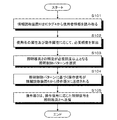
図2は、照明制御システム1の動作手順を示す。使用者が部屋に入ったとき、情報読取装置6はICタグ4から使用者情報を読み取り、使用者が部屋のいることを認識する(S101)。
FIG. 2 shows an operation procedure of the illumination control system 1. When the user enters the room, the
情報読取装置6は、読み取った使用者情報のうち、使用者自体の属性と使用者の動作属性に基づいて、使用者に必要な照明器具2の照度Xを算出する(S102)。必要照度Xは、20歳の男女の視力の平均値をY0とし、使用者が該当する年齢の視力をY1とし、JIS Z9110−1979で定められた各部屋での特定の動作に必要な明るさをZとした場合、下記の数1の数式により算出される。

さらに、情報読取装置6は、数1の数式により算出された必要照度Xを、予め登録した複数の照明制御パターンにおける照明器具2の照度と比較し、照明器具2の照度が必要照度X以上となる照明制御パターンを選択する(S103)。照明制御パターンは、予め登録された照度のパターンに合わせて照明器具2を点灯させるための制御情報である。選択された照明制御パターンに基づく操作信号が、情報読取装置6から操作器3に送信される(S104)。操作信号を受信した操作器3は、操作信号に応じた制御信号を照明器具2へ送信し、照明器具2を制御する(S105)。このように、照明制御システム1は中継装置を必要としないので、コストを抑制することができる。また、使用者情報に応じて照明器具が制御されるので、人感知センサによる照明制御の場合のように、ペット等の人間以外の動くものに反応して照明器具が点灯することを防止できる。
Furthermore, the
次に、本発明の第2の実施形態に係る照明制御システムについて図3及び図4を参照して説明する。本実施形態に係る照明制御システムは、第1の実施形態に係る照明制御システムと比べて、照明器具及び情報読取装置が同じ部屋に複数台設置される点で異なる。 Next, an illumination control system according to a second embodiment of the present invention will be described with reference to FIGS. The illumination control system according to this embodiment is different from the illumination control system according to the first embodiment in that a plurality of lighting fixtures and information reading devices are installed in the same room.
図3は、照明制御システム1の構成を示す。照明制御システム1は、照明器具2A、2Bと、照明器具2A、2Bを操作するための操作器3A、3Bと、使用者情報を記憶し、使用者に携帯されるICタグ4(情報記憶部)と、ICタグ4が取り付けられたスリッパ5と、ICタグ4に記憶される使用者情報を読み取り、該使用者情報に応じて照明器具2A、2Bを制御する情報読取装置6A、6Bと、を同じ部屋に備える。なお、照明器具、操作器及び情報読取装置は2台に限られない。
FIG. 3 shows a configuration of the illumination control system 1. The lighting control system 1 includes
情報読取装置6A、6Bは、ICタグ4から使用者情報を読み取ったとき、操作器3A、3Bのいずれか1台又は両方に操作信号を送信する。
When the
操作器3A、3Bは照明器具2A、2Bの両方を制御可能である。照明器具2A、2Bが同じ照明器具であって、同じ制御方法により制御可能である場合、操作器出力される制御信号のチャンネル番号を同じにすることにより、照明器具2A、2Bの両方を制御することができる。照明器具2A、2Bの制御方法が異なる場合、同じ部屋の中にある照明器具2A、2Bを一括して制御可能な制御部(不図示)を設け、操作器3A、3Bから制御部に制御信号を送信することにより、照明器具2A、2Bの両方を制御する。
The controllers 3A and 3B can control both the
このような構成により、広い部屋に複数台の照明器具が設置される場合に、1台の情報読取装置が使用者情報を読み取り、使用者情報に応じた操作信号を操作器に送信するとき、同じ部屋にある複数台の照明器具を制御することができ、実使用において違和感のない照明制御が可能となる。 With such a configuration, when a plurality of lighting fixtures are installed in a large room, when one information reading device reads user information and transmits an operation signal corresponding to the user information to the operating device, A plurality of lighting fixtures in the same room can be controlled, and lighting control without a sense of incongruity in actual use is possible.
図4は、照明制御システム1の動作手順を示す。ここで、使用者が、例えば情報読取装置6B近辺にいるとする。このような場合、情報読取装置6Bは使用者情報を読み取り(S201)、使用者情報及び使用者の現在位置に応じて照明制御パターンを選択し(S202)、照明制御パターンに基づく操作信号を操作器3Bに送信する(S203)。操作器3Bは操作信号を受信したとき、照明器具2A、2Bに制御信号を送信し、照明器具2A、2Bの照度を制御する(S204)。
FIG. 4 shows an operation procedure of the lighting control system 1. Here, it is assumed that the user is in the vicinity of the
使用者が情報読取装置6A近辺に移動したとき(S205)、情報読取装置6Aは使用者情報を読み取り(S206)、使用者情報及び使用者の現在位置に応じて照明制御パターンを選択し(S207)、照明制御パターンに基づく操作信号を操作器3Aに送信する(S208)。操作器3Aはこの操作信号を受信したとき、照明器具2A、2Bに制御信号を送信し、照明器具2A、2Bの照度を制御する(S209)。
When the user moves to the vicinity of the
このように、使用者の現在位置が変化したとき、使用者情報を読み取る情報読取装置が変わり、それに伴って照明器具の制御内容が変わる。このため、使用者の移動中に、情報読取装置が使用者情報を読み取ったとき、情報読取装置から照明器具までの距離の違いに応じて、照明器具の制御内容を変えることができる。例えば、使用者が近い照明器具を必要照度で点灯させ、使用者から遠い照明器具を暗く点灯させることができる。また、使用者情報を読み取った情報読取装置の位置と、当該装置が使用者情報を読み取った順番と、に応じて、複数台の照明器具を制御することができる。 As described above, when the current position of the user changes, the information reading device that reads the user information changes, and the control content of the lighting fixture changes accordingly. For this reason, when the information reading device reads the user information during the movement of the user, the control content of the lighting fixture can be changed according to the difference in the distance from the information reading device to the lighting fixture. For example, it is possible to turn on a lighting fixture that is close to the user with a required illuminance and to turn on a lighting fixture that is far from the user darkly. Further, a plurality of lighting fixtures can be controlled according to the position of the information reading device that has read the user information and the order in which the device has read the user information.
次に、本発明の第3の実施形態に係る照明制御システムについて図5及び図6を参照して説明する。本実施形態に係る照明制御システムは、上記実施形態に係る照明制御システムと比べて、情報読取装置6が複数の使用者情報を受信した場合に、それらのいずれか一つの使用者情報に基づいて照明器具が制御される点で異なる。
Next, an illumination control system according to a third embodiment of the present invention will be described with reference to FIGS. When the
図5は照明制御システムの構成を示す。照明制御システム1は、照明器具2と、照明器具2を操作するための操作器3と、使用者情報を記憶し、使用者に携帯される複数のICタグ4A、4B(情報記憶部)と、ICタグ4が取り付けられたスリッパ5A、5Bと、ICタグ4A、4Bに記憶される使用者情報を読み取り、該使用者情報に応じて照明器具2を制御する情報読取装置6と、を備える。
FIG. 5 shows the configuration of the illumination control system. The lighting control system 1 includes a
情報読取装置6は、複数のIC4A、4Bから複数の使用者情報を読み取り、これらのいずれか1つの使用者情報に応じて照明器具2を制御する。すなわち、情報読取装置6は、使用者情報のうち優先的に照明制御で参照する情報を設定してメモリに記憶し、当該情報に基づいて照明器具2を制御する。このため、情報読取装置が複数の使用者情報を受信した場合に、それらのいずれか一つの使用者情報に基づいて照明器具が制御されるので、使用者情報を読み取る度に制御内容が変わることがなく、制御の混乱を避け、安定した照明制御が可能となる。
The
図6は、照明制御システム1の動作手順を示す。ここで、同じ部屋の中に複数の使用者A、Bが、情報読取装置6により使用者情報を読取可能な位置にいるとする。
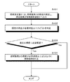
FIG. 6 shows an operation procedure of the lighting control system 1. Here, it is assumed that a plurality of users A and B are in a position where user information can be read by the
情報読取装置6は使用者Aの使用者情報と、使用者Bの使用者情報を読み取る(S301)。読取後、情報読取装置6は、各種使用者情報の優先順位を、予め設定された優先順位の情報に基づいて判断する(S302)。判断後、どちらかの使用者情報が優先的に参照され(S303)、照明器具2の点灯制御が行なわれる(S304)。ここで、使用者情報の優先順位は、必要照度の高さに基づいて定められる。このため、必要照度の一番高い人または動作内容に合わせて、照明制御することで複数の使用者の必要照度で照明器具2を点灯させることが可能となる。
The
次に、本発明の第4の実施形態に係る照明制御システムについて図7及び図8を参照して説明する。本実施形態に係る照明制御システムは、上記実施形態に係る照明制御システムと比べて、照明器具2が、照度を測定可能な照度測定器を有する点で異なる。
Next, an illumination control system according to a fourth embodiment of the present invention will be described with reference to FIGS. The illumination control system according to the present embodiment is different from the illumination control system according to the above-described embodiment in that the
図7は、照明制御システム1の構成を示す。照明制御システム1は、照明器具2と、照明器具2を操作するための操作器3と、使用者情報を記憶し、使用者に携帯されるICタグ4(情報記憶部)と、ICタグ4が取り付けられたスリッパ5と、ICタグ4に記憶される使用者情報を読み取り、該使用者情報に応じて照明器具2を制御する情報読取装置6と、照明器具2の照度を測定する照度測定器21と、を備える。
FIG. 7 shows a configuration of the illumination control system 1. The lighting control system 1 includes a
照度測定器21は、フォトダイオード、CdS(Cadmium Sulfide)等の照度を測定する照度センサを含み、照明器具2のランプ配置面側に設けられる。また、照度測定器21は、照明器具2の照度を測定し、測定結果を情報読取装置6に出力する。
The
情報読取装置6は、現在の照度が必要照度より低いか否かを判定するためのCPU等含む電気回路で構成される照度判定部61を有する。照度判定部61は、照度測定器21からの測定結果に基づき、現在の照度が、使用者情報に応じて定められる必要照度以上の照度かどうかの判定を行なう。
The
図8は、照明制御システム1の動作手順を示す。照度測定器21は、照明器具2の現在の照度を測定し、測定結果を情報読取装置6に出力する(S401)。情報読取装置6の照度判定部61は、照度測定器21からの測定結果に基づき、現在の照度が、使用者情報に応じて定められる必要照度以上の照度かどうかの判定を行なう(S402)。測定結果と必要照度とを比較して、測定結果が必要照度より低い場合(S403でYes)、照明器具2の照度が必要照度以上の照度となるように照明制御が行なわれる(S404)。照明器具2が照明制御を連続的に行える照明器具である場合、上記の作業を繰り返し行うことで、適切な明るさとなる照度で照明器具2を点灯させることができる。測定結果が必要照度より低い場合(S403でNo)、一連の動作は終了する。
FIG. 8 shows an operation procedure of the illumination control system 1. The
このような動作のため、使用者別に、また使用者の動作内容別に必要とされる必要照度以上の照度で照明器具2を点灯させることができる。また、光源の光束減退により照度が低下した場合や、照明器具2の光出射面の汚れや材質劣化により照度が低下した場合等に、必要照度以上で点灯するように照度を補正することができ、より確実に必要照度で照明器具2を点灯させることができる。
Due to such an operation, the
次に、本発明の第5の実施形態に係る照明制御システムについて図9を参照して説明する。本実施形態に係る照明制御システムは、上記実施形態に係る照明制御システムと比べて、情報読取装置6は照明器具6を自動的に消灯させる点で異なる。
Next, an illumination control system according to a fifth embodiment of the present invention will be described with reference to FIG. The illumination control system according to the present embodiment is different from the illumination control system according to the above-described embodiment in that the
図9は、照明制御システム1の構成を示す。照明制御システム1は、照明器具2と、照明器具2を操作するための操作器3と、使用者情報を記憶し、使用者に携帯されるICタグ4(情報記憶部)と、ICタグ4が取り付けられたスリッパ5と、ICタグ4に記憶される使用者情報を読み取り、該使用者情報に応じて照明器具2を制御する情報読取装置6と、時間を計るための時間計測部62と、を備える。
FIG. 9 shows the configuration of the illumination control system 1. The lighting control system 1 includes a
時間計測部62は、時間を計測するための回路であり、情報読取装置6内に設けられ、使用者情報を読み取った後の経過時間を計測する。
The time measuring unit 62 is a circuit for measuring time, and is provided in the
図10は、照明制御システム1の動作手順を示す。情報読取装置6は、使用者情報を読み取った後、経過時間を時間計測部62に計測させる(S501)。情報読取装置6は、時間計測部62により一定期間の経過を認識し、次の使用者情報を読み取らなかった場合(S502でYes)、照明器具を自動的に消灯させる(S503)。一定期間が経過していない場合であって(S502でNo)、情報読取装置6が次の使用者情報を読み取ったとき(S504でYes)、時間計測部62により計測される経過時間がリセットされ(S505)、動作はS501へ戻る。情報読取装置6が次の使用者情報を読み取らない場合(S504でNo)、動作はS502へ戻る。
FIG. 10 shows an operation procedure of the lighting control system 1. After reading the user information, the
このように、情報読取装置6が使用者情報を読み取った後、一定期間の間だけ照明器具2を点灯させることができるので、照明の消し忘れを防止することができ、照明制御システム1の省エネルギーを図ることができる。
As described above, after the
本発明は、上記のような実施形態の構成に限定されるものでなく、使用目的に応じ、様々な変形が可能である。例えば、使用者情報部はICタグ4に限られず、情報読取装置6によって使用者情報を読取可能な機器等であればよい。また、スリッパ5に取り付けられるICタグ4に限られず、使用者の情報を検知できる検知手段であってもよい。当該検知手段には、例えば、荷重を確認する重さセンサ、体温を確認する温度センサが含まれる。また、ICタグ4は、スリッパ5だけでなく、使用者が家の中で常時携帯するものに取り付けても構わない。例えば、下着、メガネ等の使用者が個々に家の中で携帯するものにICタグ4を取り付けてもよい。また、使用者情報の信号、制御信号又は操作信号の通信は無線ではなく、有線によって行なわれてもよい。
The present invention is not limited to the configuration of the embodiment as described above, and various modifications can be made according to the purpose of use. For example, the user information unit is not limited to the
また、必要照度Xは、上記の算出方法に限定されず、使用者が第1の部屋で第1の動作を行なう場合、第2の部屋で行なう第1の動作に応じた必要照度と、第2の部屋で行なう第2の動作に応じた必要照度と、の比率を求め、当該比率に、使用者が第1の部屋で行なう第2の動作に応じた必要照度を掛けることにより算出されてもよい。また、必要照度Xは、20歳時の視力により正規化されたある年齢時の視力と、使用者の該当年齢時の視力との差を係数とし、動作属性に応じて選択された照度に当該係数を掛けることにより必要照度Xを算出してもよい。また、使用者情報の優先順位は、必要照度の他に、年齢、性別、視力等の使用者情報により定められてもよい。 The required illuminance X is not limited to the above calculation method. When the user performs the first operation in the first room, the necessary illuminance according to the first operation performed in the second room, Calculated by multiplying the ratio by the required illuminance corresponding to the second operation performed by the user in the first room. Also good. In addition, the required illuminance X corresponds to the illuminance selected according to the operation attribute, with the difference between the visual acuity at a certain age normalized by the visual acuity at the age of 20 and the visual acuity at the corresponding age of the user as a coefficient. The necessary illuminance X may be calculated by multiplying by a coefficient. The priority order of user information may be determined by user information such as age, sex, eyesight, etc. in addition to the required illuminance.
また、照度測定器21は、照明器具2だけではなく、操作器3、情報記憶部及び情報読取装置6のいずれかに設けられてもよい。また、照度測定器21は独立して照明制御システム1に設けられても構わない。また、照度測定器21は、照度を測定するだけでなく、ランプ取付開始時からの経過時間、ランプ点灯累積時間等を記憶し、予め登録されたランプの光束減退曲線を用いて当該時間から光束減退の値を求めることにより現在の照度を推定してもよい。また、照度測定器21は、照度測定結果を、照度判定部61を備える操作器3に出力しても構わない。
Further, the
1 照明制御システム
2、2A、2B 照明器具
3、3A、3B 操作器
4、4A、4B ICタグ(情報記憶部)
5、5A、5B スリッパ
6、6A、6B 情報読取装置
21 照度測定器(照度測定手段)
61 照度判定部
62 時間計測部
1
5, 5A,
61 Illuminance determination unit 62 Time measurement unit
Claims (6)
使用者情報を記憶し、使用者に携帯される情報記憶部と、
前記情報記憶部に記憶される使用者情報を読み取り、該使用者情報に応じて照明器具を制御する情報読取装置と、を備える照明制御システムにおいて、
前記情報記憶部の使用者情報は、使用者自体の属性と、使用者、使用者の位置及び使用者の動作内容に応じて予め設定される使用者の動作属性と、前記使用者自体の属性と前記使用者の動作属性とに応じて選択される前記照明器具の制御情報と、を含み、
前記情報読取装置は、前記情報記憶部から使用者情報を読み取り、使用者の現在位置を認識し、使用者情報と使用者の現在位置とに基づいて前記照明器具を制御することを特徴とする照明制御システム。 Lighting equipment,
An information storage unit that stores user information and is carried by the user;
In an illumination control system comprising: an information reading device that reads user information stored in the information storage unit and controls a lighting apparatus according to the user information;
The user information of the information storage unit includes the user's own attributes, the user's operation attributes preset according to the user, the user's position and the user's operation details, and the user's own attributes. And control information of the lighting fixture selected according to the operation attribute of the user,
The information reader reads user information from the information storage unit, recognizes the current position of the user, and controls the lighting apparatus based on the user information and the current position of the user. Lighting control system.
前記情報読取装置のいずれか1台が、使用者情報を読み取ったとき、複数台の照明器具を制御することを特徴とする請求項1に記載の照明制御システム。 A plurality of the lighting fixtures and information readers are installed,
The lighting control system according to claim 1, wherein when one of the information reading devices reads user information, the lighting control system controls a plurality of lighting fixtures.
前記照度測定手段は、前記照明器具の照度を測定し、測定結果を前記情報読取装置に出力し、
前記情報読取装置は、該照度が、使用者情報に応じて定められる照度以上の照度かどうかの判定を行なうことを特徴とする請求項1乃至請求項5のいずれかに記載の照明制御システム。
The lighting fixture has illuminance measuring means capable of measuring illuminance,
The illuminance measuring means measures the illuminance of the lighting fixture, and outputs a measurement result to the information reading device,
The illumination control system according to claim 1, wherein the information reading device determines whether the illuminance is equal to or higher than an illuminance determined according to user information.
Priority Applications (1)
| Application Number | Priority Date | Filing Date | Title |
|---|---|---|---|
| JP2006017962A JP2007200715A (en) | 2006-01-26 | 2006-01-26 | Lighting control system |
Applications Claiming Priority (1)
| Application Number | Priority Date | Filing Date | Title |
|---|---|---|---|
| JP2006017962A JP2007200715A (en) | 2006-01-26 | 2006-01-26 | Lighting control system |
Publications (1)
| Publication Number | Publication Date |
|---|---|
| JP2007200715A true JP2007200715A (en) | 2007-08-09 |
Family
ID=38455113
Family Applications (1)
| Application Number | Title | Priority Date | Filing Date |
|---|---|---|---|
| JP2006017962A Withdrawn JP2007200715A (en) | 2006-01-26 | 2006-01-26 | Lighting control system |
Country Status (1)
| Country | Link |
|---|---|
| JP (1) | JP2007200715A (en) |
Cited By (10)
| Publication number | Priority date | Publication date | Assignee | Title |
|---|---|---|---|---|
| JP2009252728A (en) * | 2008-04-11 | 2009-10-29 | Takenaka Komuten Co Ltd | Personal illumination system |
| JP2011070881A (en) * | 2009-09-25 | 2011-04-07 | Toshiba Lighting & Technology Corp | Lighting control device |
| US8078318B2 (en) | 2008-05-28 | 2011-12-13 | Kabushiki Kaisha Toshiba | Appliance control apparatus and method |
| JP2012028015A (en) * | 2010-07-20 | 2012-02-09 | Toshiba Corp | Illumination control system and illumination control method |
| JP2014099359A (en) * | 2012-11-15 | 2014-05-29 | Panasonic Corp | Illumination system |
| WO2014147683A1 (en) * | 2013-03-19 | 2014-09-25 | パナソニック株式会社 | Environment control system |
| JP2015065037A (en) * | 2013-09-25 | 2015-04-09 | パナソニック株式会社 | Lighting control system |
| KR101816993B1 (en) * | 2015-05-15 | 2018-01-09 | 아즈빌주식회사 | Illumination control system and illumination control method |
| US10334709B2 (en) | 2017-10-11 | 2019-06-25 | Panasonic Intellectual Property Management Co., Ltd. | Lighting system |
| CN114158166A (en) * | 2020-09-07 | 2022-03-08 | 中国联合网络通信集团有限公司 | Control method and device of lighting equipment |
-
2006
- 2006-01-26 JP JP2006017962A patent/JP2007200715A/en not_active Withdrawn
Cited By (12)
| Publication number | Priority date | Publication date | Assignee | Title |
|---|---|---|---|---|
| JP2009252728A (en) * | 2008-04-11 | 2009-10-29 | Takenaka Komuten Co Ltd | Personal illumination system |
| US8078318B2 (en) | 2008-05-28 | 2011-12-13 | Kabushiki Kaisha Toshiba | Appliance control apparatus and method |
| JP2011070881A (en) * | 2009-09-25 | 2011-04-07 | Toshiba Lighting & Technology Corp | Lighting control device |
| JP2012028015A (en) * | 2010-07-20 | 2012-02-09 | Toshiba Corp | Illumination control system and illumination control method |
| US8836505B2 (en) | 2010-07-20 | 2014-09-16 | Kabushiki Kaisha Toshiba | Illumination control system and method for controlling illumination |
| JP2014099359A (en) * | 2012-11-15 | 2014-05-29 | Panasonic Corp | Illumination system |
| WO2014147683A1 (en) * | 2013-03-19 | 2014-09-25 | パナソニック株式会社 | Environment control system |
| JP2015065037A (en) * | 2013-09-25 | 2015-04-09 | パナソニック株式会社 | Lighting control system |
| KR101816993B1 (en) * | 2015-05-15 | 2018-01-09 | 아즈빌주식회사 | Illumination control system and illumination control method |
| US10334709B2 (en) | 2017-10-11 | 2019-06-25 | Panasonic Intellectual Property Management Co., Ltd. | Lighting system |
| CN114158166A (en) * | 2020-09-07 | 2022-03-08 | 中国联合网络通信集团有限公司 | Control method and device of lighting equipment |
| CN114158166B (en) * | 2020-09-07 | 2023-05-16 | 中国联合网络通信集团有限公司 | Control method and device of lighting equipment |
Similar Documents
| Publication | Publication Date | Title |
|---|---|---|
| JP2007200715A (en) | Lighting control system | |
| KR20120003489A (en) | System for controlling a plurality of light sources | |
| JP2011009066A (en) | Lighting system | |
| JP2009087834A (en) | Illuminance control system and its program | |
| JP2017021932A (en) | Led illumination system | |
| JP6532824B2 (en) | Lighting control analyzer | |
| JP2019071251A (en) | Illumination control system and tenant management system | |
| JP2014186961A (en) | Electric apparatus control system | |
| KR20190044198A (en) | A Smart Lighting System | |
| KR101314199B1 (en) | A led lighting unit changing surrindings temperature and led lighting method thereof | |
| JP2010098900A (en) | Power monitoring device | |
| JPWO2014076793A1 (en) | Remote controller, air conditioning system and program | |
| JP5264190B2 (en) | Lighting control system | |
| JP4956844B2 (en) | Device control apparatus and device control method | |
| KR101597664B1 (en) | Energy-saving inner lighting apparatus | |
| JP5062617B2 (en) | Lighting system | |
| JP2004228051A (en) | Lighting control device and lighting system | |
| JP2012043626A (en) | Illumination system | |
| KR100927744B1 (en) | A automatic lighting unit by steps using photosensing and lighting method thereof | |
| JP2008084588A (en) | Lighting control system | |
| JP2012174618A (en) | Illumination control method and illumination control system | |
| JP2010123483A (en) | Illumination system | |
| JP5938369B2 (en) | Sensing unit | |
| JP2010186635A (en) | Illumination apparatus, illumination system, and illumination method | |
| KR101673801B1 (en) | Lighting control system and method of controlling the same |
Legal Events
| Date | Code | Title | Description |
|---|---|---|---|
| A300 | Application deemed to be withdrawn because no request for examination was validly filed |
Free format text: JAPANESE INTERMEDIATE CODE: A300 Effective date: 20090407 |