JP2007199028A - Indicating instrument - Google Patents
Indicating instrument Download PDFInfo
- Publication number
- JP2007199028A JP2007199028A JP2006020848A JP2006020848A JP2007199028A JP 2007199028 A JP2007199028 A JP 2007199028A JP 2006020848 A JP2006020848 A JP 2006020848A JP 2006020848 A JP2006020848 A JP 2006020848A JP 2007199028 A JP2007199028 A JP 2007199028A
- Authority
- JP
- Japan
- Prior art keywords
- display panel
- light source
- display
- pointer
- light
- Prior art date
- Legal status (The legal status is an assumption and is not a legal conclusion. Google has not performed a legal analysis and makes no representation as to the accuracy of the status listed.)
- Granted
Links
- 238000005286 illumination Methods 0.000 claims abstract description 29
- 230000008878 coupling Effects 0.000 claims abstract description 3
- 238000010168 coupling process Methods 0.000 claims abstract description 3
- 238000005859 coupling reaction Methods 0.000 claims abstract description 3
- 239000000758 substrate Substances 0.000 claims description 14
- 239000004973 liquid crystal related substance Substances 0.000 description 5
- 239000000463 material Substances 0.000 description 5
- 238000005192 partition Methods 0.000 description 5
- 229920003002 synthetic resin Polymers 0.000 description 5
- 239000000057 synthetic resin Substances 0.000 description 5
- 239000003086 colorant Substances 0.000 description 3
- 230000005855 radiation Effects 0.000 description 3
- 239000008358 core component Substances 0.000 description 2
- 238000005259 measurement Methods 0.000 description 2
- 239000000306 component Substances 0.000 description 1
- 239000000428 dust Substances 0.000 description 1
- 230000000694 effects Effects 0.000 description 1
- 238000005401 electroluminescence Methods 0.000 description 1
- 239000000446 fuel Substances 0.000 description 1
- 230000003287 optical effect Effects 0.000 description 1
- 238000001579 optical reflectometry Methods 0.000 description 1
- 230000000644 propagated effect Effects 0.000 description 1
- 238000010079 rubber tapping Methods 0.000 description 1
- 238000000638 solvent extraction Methods 0.000 description 1
- 230000000007 visual effect Effects 0.000 description 1
Images


Classifications
-
- G—PHYSICS
- G01—MEASURING; TESTING
- G01D—MEASURING NOT SPECIALLY ADAPTED FOR A SPECIFIC VARIABLE; ARRANGEMENTS FOR MEASURING TWO OR MORE VARIABLES NOT COVERED IN A SINGLE OTHER SUBCLASS; TARIFF METERING APPARATUS; MEASURING OR TESTING NOT OTHERWISE PROVIDED FOR
- G01D11/00—Component parts of measuring arrangements not specially adapted for a specific variable
- G01D11/28—Structurally-combined illuminating devices
-
- B—PERFORMING OPERATIONS; TRANSPORTING
- B60—VEHICLES IN GENERAL
- B60K—ARRANGEMENT OR MOUNTING OF PROPULSION UNITS OR OF TRANSMISSIONS IN VEHICLES; ARRANGEMENT OR MOUNTING OF PLURAL DIVERSE PRIME-MOVERS IN VEHICLES; AUXILIARY DRIVES FOR VEHICLES; INSTRUMENTATION OR DASHBOARDS FOR VEHICLES; ARRANGEMENTS IN CONNECTION WITH COOLING, AIR INTAKE, GAS EXHAUST OR FUEL SUPPLY OF PROPULSION UNITS IN VEHICLES
- B60K35/00—Arrangement of adaptations of instruments
-
- B60K35/215—
-
- B60K35/60—
-
- G—PHYSICS
- G01—MEASURING; TESTING
- G01D—MEASURING NOT SPECIALLY ADAPTED FOR A SPECIFIC VARIABLE; ARRANGEMENTS FOR MEASURING TWO OR MORE VARIABLES NOT COVERED IN A SINGLE OTHER SUBCLASS; TARIFF METERING APPARATUS; MEASURING OR TESTING NOT OTHERWISE PROVIDED FOR
- G01D13/00—Component parts of indicators for measuring arrangements not specially adapted for a specific variable
- G01D13/22—Pointers, e.g. settable pointer
-
- G—PHYSICS
- G01—MEASURING; TESTING
- G01D—MEASURING NOT SPECIALLY ADAPTED FOR A SPECIFIC VARIABLE; ARRANGEMENTS FOR MEASURING TWO OR MORE VARIABLES NOT COVERED IN A SINGLE OTHER SUBCLASS; TARIFF METERING APPARATUS; MEASURING OR TESTING NOT OTHERWISE PROVIDED FOR
- G01D7/00—Indicating measured values
- G01D7/002—Indicating measured values giving both analog and numerical indication
-
- B60K2360/33—
-
- B60K2360/336—
-
- B60K2360/6985—
Abstract
Description
本発明は、車両等に搭載する指示計器に関するものであって、指針と表示板とでなる指針式表示部の中央で電子式の表示パネルによる情報表示を行うべく、指針が表示パネルの後方を迂回して表示板の前方に至るタイプの指示計器に関するものである。 The present invention relates to an indicating instrument mounted on a vehicle or the like, and the pointer moves behind the display panel in order to display information on an electronic display panel at the center of a pointer-type display unit composed of a pointer and a display board. The present invention relates to an indicating instrument that bypasses and reaches the front of the display board.
この種の指示計器として、例えば下記特許文献1に記載されているものが知られている。この指示計器は、液晶パネルからなる表示パネルと、この表示パネルの外周に沿って指標部が配された表示板と、指標部を指示する指針と、この指針を駆動すべく表示パネルの背後に配置された駆動源(回動内機)と、この駆動源を装着すると共に表示パネルとは所定の間隔を明けて配置される回路基板と、この回路基板の前方に配置され表示板と表示パネルとを照明する光源とを備えている。指針はその回転基部が駆動源の駆動軸に連結され、表示パネルの後方を迂回して自由端側が表示板の前方に至るように屈曲している。このように屈曲した指針の動作を可能とするため、表示パネルと回路基板との間隔は、指針の作動を許容できる大きさに設定されている。そして回路基板上に位置する光源は前記間隔を隔てて表示板や表示パネルと対向し、光源の点灯により表示板や表示パネルを照明する構造である。
しかしながら上記特許文献1では、表示板と表示パネルに対して光源を、指針の作動を許容するための間隔を隔てて対向させる構造に過ぎないため、光源から照明対象である表示板や表示パネルへ至る光路をコントロールするのが難しく、照明効率の低下を招きやすいという問題がある。また例えば異なる色の光源を用い、表示板と表示パネルとを異なる色で照明する場合に対応できないという問題もある。
本発明はこの点に着目してなされたもので、その主な目的は、照明効率を向上させることが可能な指示計器を提供することにある。
However, in the above-mentioned
The present invention has been made paying attention to this point, and its main object is to provide an indicating instrument capable of improving illumination efficiency.
本発明は、前述した課題を解決するため、表示パネルと、この表示パネルの外周に沿って指標部が配された表示板と、前記指標部を指示する指針と、この指針を駆動する駆動源と、少なくとも前記表示板を照明する光源とを備え、前記指針が前記表示パネルの後方を迂回して前記表示板の前方に至る指示計器において、前記表示パネルと前記表示板と前記光源とを結合する枠体を設け、この枠体に前記光源の光を前記表示板に導く照明室を設けたことを特徴とする。 In order to solve the above-described problems, the present invention provides a display panel, a display board in which an indicator portion is arranged along the outer periphery of the display panel, a pointer that points to the indicator portion, and a drive source that drives the pointer. And at least a light source that illuminates the display panel, and the indicator panel bypasses the rear of the display panel and leads to the front of the display panel, and the display panel, the display board, and the light source are combined. And a lighting chamber for guiding the light from the light source to the display plate.
また本発明は、前記枠体が前記指針の非移動領域において所定の剛体に連結されることを特徴とする。 Further, the present invention is characterized in that the frame body is connected to a predetermined rigid body in a non-moving region of the pointer.
また本発明は、前記光源を装着する光源基板を有し、この光源基板を介して前記光源が前記枠体と合体されることを特徴とする。 Moreover, this invention has a light source board | substrate which mounts the said light source, The said light source is united with the said frame through this light source board | substrate, It is characterized by the above-mentioned.
また本発明は、前記光源が前記表示板に加えて前記表示パネルも照らす光源か、または前記表示板と前記表示パネルとを別々に照らす光源からなり、前記照明室が前記表示板を照明する照明室と前記表示パネルを照明する照明室とに区画されることを特徴とする。 Further, the present invention is an illumination in which the light source is a light source that illuminates the display panel in addition to the display plate or a light source that separately illuminates the display plate and the display panel, and the illumination chamber illuminates the display plate It is divided into a room and an illumination room for illuminating the display panel.
本発明によれば、照明効率を向上させることが可能な指示計器を提供することができる。 According to the present invention, it is possible to provide an indicating instrument capable of improving illumination efficiency.
以下、添付図面に基づいて、本発明を適用した指示計器の実施形態を説明する。 Embodiments of an indicating instrument to which the present invention is applied will be described below with reference to the accompanying drawings.
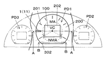
図1から図4は、本発明の第1の実施形態を示す。図1は指示計器の正面図、図2は、図1のA−A断面図、図3は、表示ユニットとケースの一部を示す斜視図、図4は図2のB−B断面図である。 1 to 4 show a first embodiment of the present invention. 1 is a front view of the indicating instrument, FIG. 2 is a cross-sectional view taken along line AA in FIG. 1, FIG. 3 is a perspective view showing a part of the display unit and the case, and FIG. 4 is a cross-sectional view taken along line BB in FIG. is there.
本実施形態による指示計器は、例えば自動車のダッシュボードに搭載されるコンビネーションメータからなるもので、図1に示すように、異なる種類の計測値を表示する三つの指針式表示部を横一列に配列してなり、全体の外形形状は略蒲鉾形である。なお図1では中央に位置する指針式表示部PD1のみ詳細に示し、両脇に位置する指針式表示部PD2,3は、一点鎖線にて示す。 The indicator instrument according to the present embodiment is composed of, for example, a combination meter mounted on a dashboard of an automobile. As shown in FIG. 1, three pointer type display units for displaying different types of measurement values are arranged in a horizontal row. Thus, the overall outer shape is substantially bowl-shaped. In FIG. 1, only the pointer type display part PD1 located in the center is shown in detail, and the pointer type display parts PD2 and 3 located on both sides are shown by a one-dot chain line.
各指針式表示部PD1〜PD3は、表示するコンテンツ(計測値の種類等)が異なるだけでその機械的構成は基本部分で一致しており、指針式表示部PD1を代表として図2に示すように、指針1と表示ユニットU(共に後に詳述)とにより構成されている。
Each of the pointer type display units PD1 to PD3 is different only in the contents to be displayed (types of measurement values, etc.), and the mechanical configuration is the same in the basic part. As shown in FIG. 2, the pointer type display unit PD1 is representative. The
これら指針1と表示ユニットUの前方には、遮蔽部材(見返し部材またはマスク部材)2が配置され、この遮蔽部材2は、例えば遮光性の合成樹脂材料(例えば黒色)からなり、指針式表示部PD1〜PD3の所要部を露出し、不要部を隠蔽する開口が形成されている。
A shielding member (look-back member or mask member) 2 is disposed in front of the
遮蔽部材2の前方には、例えば透光性の合成樹脂材料(例えば無色透明)からなるフロントカバー3が設けられ、埃等の進入を防いでいる。
A
一方、表示ユニットUの後方(背後)には、ケース(剛体)4、回路基板5、リアカバー6がそれぞれ位置している。
On the other hand, a case (rigid body) 4, a
ケース4は、各指針式表示部PD1〜PD3を構成する指針1や表示ユニットU他を収容する、概略形状が有底枠体からなる剛体であって、遮蔽部材2、フロントカバー3、回路基板5、リアカバー6を直接的または間接的に装着するコア部品となるものである。
The case 4 is a rigid body having a substantially bottomed frame body that accommodates the
そして、このケース4(の底部)と回路基板5との間には、指針1の動作を許容する空間部Sが形成されている。
A space S that allows the movement of the
回路基板5は、ケース4(の底部)の背後に配置される硬質の回路基板であり、その背面には例えばステッピングモータからなる駆動源7の本体部が装着され、この駆動源7の駆動軸71は回路基板5を貫通して前方に延び、指針1に接続されている。また回路基板5の前面であって駆動軸71の周りには、指針1を照明するための例えば発光ダイオードからなる指針用光源8が配置されている。
The
リアカバー6は、回路基板5の背面を覆ってこれを保護するものである。
The
以上、リアカバー6、回路基板5、ケース4、指針式表示部PD1〜PD3を構成する指針1及び表示ユニットU、遮蔽部材2、フロントカバー1によって、コンビネーションメータが構成される。
As described above, the
次に指針1と表示ユニットUの詳細構造について説明する。
Next, the detailed structure of the
指針1は、観察者によって視認可能な第1の部分11と、視認不可能な第2の部分12と、これら第1,第2の部分11,12を連結するための連結部材13とで構成され、第1、第2の部分11,12は共に例えば透明な合成樹脂材料からなり、連結部材13は例えば遮光性の合成樹脂材料(例えば黒色)からなる。
The
第1の部分11は、表示ユニットUの前面(後述する表示板)に沿ってテーパ形状に延びる棒状であり、その背面または前面には、視認色を決定するための図示しないホットスタンプ層からなる着色層が設けられている。
The
第2の部分12は、表示ユニットUの側面から背面にかけてクランク形状に迂回して延びる棒状体かなり、指針用光源7から入光した光をその長手方向に向けて反射する反射部12aと、駆動軸71に沿って延び駆動軸71に挿入連結されるボス部12bとを備え、ボス部12bとは反対側となる自由端部は、第1の部分11に対向している。
The
連結部材13は、第1,第2の部分11,12のそれぞれを部分的に収納する概略箱形形状をなしている。
The connecting
このように構成される指針1は、表示ユニットU(後述する表示パネル)の後方を迂回して表示ユニットU(後述する表示板)の前方に至り、駆動源7の駆動軸71の回転に伴い、駆動軸71を基準として表示ユニットUの外周を回転(回動)移動する。また指針用光源8の点灯時には、第2の部分12を通じて第1の部分に光が導かれ、第1の部分12が発光する。
The
表示ユニットUは、表示パネル100と、表示板200と、枠体300と、導光体400と、光源基板500と、表示パネル用光源(光源)600と、表示板用光源(光源)700と、ネジ800とで構成されている。なお各光源600,700は例えば発光ダイオードからなるものである。
The display unit U includes a
表示パネル100は、例えばSTN(Super Twisted Nematic)やTN(Twisted Nematic)等の液晶表示パネルからなり、表示ユニットUの中央に配置され、様々な情報(例えば外気温情報、走行距離情報、燃費情報からなる車両情報や例えばナビゲーション情報からなる交通情報)を表示する。なお表示パネル100自体は、フロントカバー3側から見て矩形であるが、台形や円形等、任意形状のパネルを用いることができる。
The
表示板200は、表示パネル100の外周に沿って配置され、指針1の支持対象となる指標部201(目盛や文字からなるが図1では目盛だけを示し文字は省略する)と、表示パネル100の所要部を露出する窓部202とを有し、この窓部202から表示パネル100が視認されることで、表示板200は、結果として表示パネル100の外周に位置することになる。なお表示板200は、表示パネル100を視認でき、且つ指標部201が表示パネル100の外周に位置すればよく、窓部202に替えて透明な透視部を設けてもよい。また表示板100自体は、例えば、指標部201が透過性、それ以外が遮光性に形成された通常の透過型印刷表示板が採用され、フロントカバー3側から見た外形形状は、略D字形である。
The
枠体300は、例えば光反射性の良好な白色の合成樹脂材料からなり、フロントカバー3側から見た外形形状は、表示板200の形状に対応する略D字形である。この枠体300は壁状の仕切部301により区画され、表示板200に対応する第1の照明室R1と、表示パネル100に対応する第2の照明室R2とが形成されている。
The
第1の照明室R1は、指標部201の配列形状に沿った円弧形状に形成され、その前方側には表示板200が搭載され、また背面側には表示板用光源700が配置され、さらに表示板200と表示板用光源700との間には、導光体400が配置されている。
The first illumination room R1 is formed in an arc shape along the arrangement shape of the
導光体400は、この例では第1の照明室R1に沿った円弧形状に形成され、表示板用光源700に対応する位置には、表示板用光源700に向けて突出する光導入部401と、円錐形状の放射反射部402が形成されている。
In this example, the
そして表示板用光源700が点灯すると、その光は光導入部401を介して導光体400内に導入され、放射反射部で放射状に反射されることで表示板200の板面方向に伝播し、これにより点光源を用いて指標部201の比較的広い範囲を照明できるようにしていると共に、表示板用光源700から表示板200に至る照明経路を第1の照明室R1(仕切部301)で区画することにより、光の漏洩やロスを抑制することができる。
When the
一方、第2の照明室R2は、この例では、前方側が幅広、その反対側が幅狭の四角錐形状に形成され、幅広となる前方側には表示パネル100が搭載され、幅狭となる背面側には表示パネル用光源600が配置されている。
On the other hand, in this example, the second illumination room R2 is formed in a quadrangular pyramid shape having a wide front side and a narrow side on the opposite side. The
そして表示パネル用光源600が点灯すると、その光は第2の照明室R2内を繰り返し反射し、結果として点光源を用いて表示パネル100全域を照明できるようにしている戸共に、表示パネル用光源600から表示パネル100に至る照明経路を第2の照明室R2(仕切部301)で区画することにより、光の漏洩やロスを抑制することができる。
When the
光源基板500は、その前面側に表示パネル用光源600と表示板用光源700とが装着されており、枠体300の背後にネジ800を通じて組み付け固定されることで、表示パネル用光源600と表示板用光源700とが各照明室R1,R2内に位置するようになっている。
The
ここで、枠体300は、表示パネル100、表示板200、導光体400、光源基板500(表示パネル用光源600、表示板用光源700)とを結合する中核部品となるものである。なお本例では、枠体300に表示パネル100、表示板200、導光体400、光源基板500のそれぞれをフックや両面テープ等により直接、結合したが、他の部材を通じて間接的に結合するものであってもよい。また本例では、光源基板500と枠体300との組み付けに際してネジ800を用いたが、これら部品どうしの結合に限らず、固定部材、固定手段は任意の手段を採用できる。
Here, the
以上のように構成される表示ユニットUは、図3,図4に示すように、枠体300に形成された取付部302を通じてケース4に片持ち状態で取り付け固定される。
As shown in FIGS. 3 and 4, the display unit U configured as described above is attached and fixed to the case 4 in a cantilever manner through an
すなわち、枠体300の背面側であって、指針1の移動領域(範囲)MA対応領域から外れた非移動領域NMA対応領域(投影領域)に位置する領域(図1参照)には、指針1の動作を妨げないように取付部302が形成してあり、この例では取付部302は、ケース4側に延びる一対の円筒状突出部であって、その内部には例えばセルフタッピングネジからなる固定部材Fが螺合する孔部303が形成されている。
That is, on the back side of the
一方、取付部302に対応するケース4位置には、取付受部41が形成してあり、この例では、取付受部41は、取付部302に向けて開口する円筒形状に形成され、その内部には取付部302を挿入及び位置決め可能な凹部42が形成され、この凹部42の底部には固定部材Fを挿通可能な孔部43が形成されている。なおケース4の背後に位置する回路基板5とリアカバー6のそれぞれには、固定部材Fを挿通する貫通孔51,61が設けられている。
On the other hand, an
表示ユニットUのケース4に対する組み付けは、表示ユニットUの取付部302をケース4の取付受部41(凹部42)内に挿入して仮止めし、その後、ケース4の背後に回路基板5とリアケース6を重ねてこれらに設けられた各貫通孔51,61と、ケース4及び取付部302に設けられた各孔部43,303とを位置合わせし、その後、背後(リアカバー6側)から貫通孔51,61と孔部43内に固定部材Fを挿入して、さらに固定部材Fの先端側を孔部303に螺着することにより行われ、これにより、表示ユニットUが、指針1の作動を妨げることなく、剛体であるケース4に方持ち状態で安定的に固定される。
Assembling of the display unit U to the case 4 is performed by inserting the
なお表示ユニットUのケース4に対する組み付けは、指針1の非移動領域NMAにおいてケース4に連結されるものであれば、上記のごとき取付部302と取付受部41のごとき凹凸嵌合に替えて、表示ユニットUとケース4との間に専用の取付具を介在させてもよい。
また表示ユニットUの取り付け対象は、表示ユニットUを安定的に支持できる剛体であればケース1に限らず任意であり、例えば回路基板5やリアカバー6、遮蔽部材2、その他の部材であてもよい。
さらに取付部302は、仮想回転中心VCを基点として扇状に広がる指針1の移動領域MAを外れた領域であれば、図1のように非移動領域NMA対応領域内における指針1の回動軌道の延長軌道上に設けてもよいし、延長軌道上に対し外側または内側であってもよい。
If the display unit U is assembled to the case 4 in the non-moving area NMA of the
The display unit U is not limited to the
Further, if the
以上の通り、本実施形態では、表示パネル1と、この表示パネル1の外周に沿って指標部201が配された表示板200と、指標部201を指示する指針1と、この指針1を駆動する駆動源7と、表示板200を照明する表示板用光源(光源)700とを備え、指針1が表示パネル1の後方を迂回して表示板200の前方に至る指示計器において、表示パネル1と表示板200と表示板用光源700とを結合する枠体300を設け、この枠体300に表示板用光源700の光を表示板200に導く照明室R1を設けたことにより、照明効率を向上させることができる。すなわち、表示板用光源700から表示板200に至る照明経路を第1の照明室R1(仕切部301)で区画することにより、光の漏洩やロスを抑制すると共に照明室R1の壁面の反射作用を利用して表示板200を効率良く照明することができる。
As described above, in the present embodiment, the
また本実施形態では、枠体300が指針1の非移動領域NMAにおいてケース4に連結されることにより、指針1の動作に影響を及ぼすことなく、表示ユニットU(枠体300)を取り付けることができる。また指針1の動作には直接寄与しない余剰(余裕)スペースを活用して、取り付けることができるので、スペースの有効活用をはかることができる。
In the present embodiment, the
また本実施形態では、表示板用光源700を装着する光源基板500を有し、この光源基板500を介して光源1が枠体300と合体されることにより、表示板用光源700を枠体300と合体するにあたり、コードや専用の保持具等が不要となり、必要最小限の部品で表示板用光源700を枠体300に装着することができる。
In the present embodiment, the
また本実施形態では、光源が表示板200を照らす表示板用光源700と表示パネル100を照らす表示パネル用光源600とからなり、照明室が表示板200を照明する照明室R1と表示パネル100を照明する照明室R2とに区画されることにより、表示板200と表示パネル100とを別々に照明できることから、表示板200だけなく、表示パネル100も効率良く照明することができる。またこの構造によれば、表示板200と表示パネル100とを互いの色干渉を防止しながら別々の光源色で照明することもできる。
Further, in the present embodiment, the
なお本実施形態では、表示パネル100として、液晶表示パネルを用いたが、表示パネルあるいは表示パネルを用いた情報表示手段であれば、任意のものを採用でき、例えば液晶表示パネルに替えて電界発光素子や蛍光表示管のような表示パネルを設けてもよいし(この場合、表示パネル用光源600は不要)、液晶表示パネルあるいは表示ユニットUに替えて、表示パネルとして通常の印刷文字板を採用した指針式の表示ユニットを設けてもよい。
In the present embodiment, a liquid crystal display panel is used as the
また本実施形態では、表示ユニットUが、表示板200と表示パネル100とを有する例を示したが、表示ユニットUには、これらに加えて、他の表示・報知手段を組み込んでもよい。
In the present embodiment, an example in which the display unit U includes the
図5は、本発明の第2の実施形態を示す要部断面図であり、本実施形態では一つの照明室Rで、表示板200と表示パネル100の双方を照明する例を示している。
FIG. 5 is a cross-sectional view of a main part showing a second embodiment of the present invention. In this embodiment, an example in which both the
すなわち、枠体300には、単一の照明室Rが形成され、その前方には表示板200と表示パネル100とが配置されている。
That is, a single illumination room R is formed in the
これら表示板200及び表示パネル100と、光源基板500との間には、導光体400が配置され、光源900からの光を導光体LGを用いて表示板200及び表示パネル100に導き、これらを照明するようになっている。
A
このように構成された第2の実施形態によっても、前記第1の実施形態と同様の効果を期待できる。 According to the second embodiment configured as described above, the same effect as that of the first embodiment can be expected.
なお前記第1,第2の実施形態では、指針1の第1の部分11が表示ユニットUの外側から中心側に延びる(指針1が表示ユニットUに対して「コ」字状に迂回する)例を示したが、表示ユニットU(枠体300,表示板200,光源基板500)に指針1が通る(作動可能な)スリットを設け、このスリットを介して指針1が動作するように構成することで、指針1を「T」字またはクランク形状に設定してもよい。
In the first and second embodiments, the
1 指針
2 遮蔽部材
3 フロントカバー
4 ケース(剛体)
5 回路基板
6 リアカバー
7 駆動源
8 指針用光源
11 第1の部分
12 第2の部分
12a 反射部
12b ボス部
13 連結部材
41 取付受部
42 凹部
43 孔部
51,61 貫通孔
71 駆動軸
100 表示パネル
200 表示板
201 指標部
202 窓部
300 枠体
301 仕切部
302 取付部
303 孔部
400 導光体
401 光導入部
402 放射反射部
500 光源基板
600 表示パネル用光源(光源)
700 表示板用光源(光源)
800 ネジ
900 光源
F 固定部材
MA 移動領域
NMA 非移動領域
PD1〜PD3 指針式表示部
R 照明室
R1 第1の照明室
R2 第2の照明室
S 空間部
U 表示ユニット
VC 仮想回転中心
1
5
700 Light source for display panel (light source)
800
Claims (4)
この表示パネルの外周に沿って指標部が配された表示板と、
前記指標部を指示する指針と、
この指針を駆動する駆動源と、
少なくとも前記表示板を照明する光源とを備え、
前記指針が前記表示パネルの後方を迂回して前記表示板の前方に至る指示計器において、
前記表示パネルと前記表示板と前記光源とを結合する枠体を設け、この枠体に前記光源の光を前記表示板に導く照明室を設けたことを特徴とする指示計器。 A display panel;
A display board in which an indicator portion is arranged along the outer periphery of the display panel;
A guideline indicating the indicator part;
A drive source for driving the pointer,
A light source for illuminating at least the display board,
In the indicating instrument that the pointer bypasses the rear of the display panel and reaches the front of the display board,
An indicator instrument comprising: a frame for coupling the display panel, the display plate, and the light source; and an illumination chamber for guiding light from the light source to the display plate.
Priority Applications (6)
| Application Number | Priority Date | Filing Date | Title |
|---|---|---|---|
| JP2006020848A JP4895321B2 (en) | 2006-01-30 | 2006-01-30 | Indicating instrument |
| EP06834574.3A EP1980825B1 (en) | 2006-01-30 | 2006-12-13 | Indication instrument |
| CN2006800519360A CN101336363B (en) | 2006-01-30 | 2006-12-13 | Indication instrument |
| US12/162,734 US7743726B2 (en) | 2006-01-30 | 2006-12-13 | Indication instrument |
| KR1020087020016A KR101363197B1 (en) | 2006-01-30 | 2006-12-13 | Indication instrument |
| PCT/JP2006/324819 WO2007086205A1 (en) | 2006-01-30 | 2006-12-13 | Indication instrument |
Applications Claiming Priority (1)
| Application Number | Priority Date | Filing Date | Title |
|---|---|---|---|
| JP2006020848A JP4895321B2 (en) | 2006-01-30 | 2006-01-30 | Indicating instrument |
Publications (2)
| Publication Number | Publication Date |
|---|---|
| JP2007199028A true JP2007199028A (en) | 2007-08-09 |
| JP4895321B2 JP4895321B2 (en) | 2012-03-14 |
Family
ID=38309007
Family Applications (1)
| Application Number | Title | Priority Date | Filing Date |
|---|---|---|---|
| JP2006020848A Expired - Fee Related JP4895321B2 (en) | 2006-01-30 | 2006-01-30 | Indicating instrument |
Country Status (6)
| Country | Link |
|---|---|
| US (1) | US7743726B2 (en) |
| EP (1) | EP1980825B1 (en) |
| JP (1) | JP4895321B2 (en) |
| KR (1) | KR101363197B1 (en) |
| CN (1) | CN101336363B (en) |
| WO (1) | WO2007086205A1 (en) |
Cited By (1)
| Publication number | Priority date | Publication date | Assignee | Title |
|---|---|---|---|---|
| JP2009204390A (en) * | 2008-02-27 | 2009-09-10 | Nippon Seiki Co Ltd | Display apparatus |
Families Citing this family (14)
| Publication number | Priority date | Publication date | Assignee | Title |
|---|---|---|---|---|
| JP4762590B2 (en) * | 2005-03-31 | 2011-08-31 | 日本精機株式会社 | Indicating instrument |
| JP5196310B2 (en) * | 2008-08-28 | 2013-05-15 | 日本精機株式会社 | Pointer-type instrument |
| US20100154700A1 (en) * | 2008-12-22 | 2010-06-24 | Visteon Global Technologies, Inc. | Instrument Gauge And Pointer |
| JP5308869B2 (en) * | 2009-03-03 | 2013-10-09 | 矢崎総業株式会社 | Instrument device |
| JP5354477B2 (en) * | 2009-07-16 | 2013-11-27 | 日本精機株式会社 | Indicating instrument |
| DE102010035240A1 (en) * | 2009-10-24 | 2011-05-12 | Johnson Controls Automotive Electronics Gmbh | Indicator with a pointer |
| JP5434780B2 (en) * | 2010-04-28 | 2014-03-05 | 日本精機株式会社 | Pointer-type instrument |
| FR2970441A1 (en) * | 2011-01-17 | 2012-07-20 | Johnson Contr Automotive Elect | DASHBOARD AND METHOD OF ASSEMBLING A DASHBOARD |
| JP2012181089A (en) * | 2011-03-01 | 2012-09-20 | Yazaki Corp | Assembly structure and assembly method for display device |
| JP6002555B2 (en) * | 2012-11-26 | 2016-10-05 | 矢崎総業株式会社 | Guideline structure |
| JP5708628B2 (en) * | 2012-12-06 | 2015-04-30 | 株式会社デンソー | Display device |
| JP6263842B2 (en) * | 2013-02-22 | 2018-01-24 | 日本精機株式会社 | Display device |
| DE102016202150A1 (en) * | 2016-02-12 | 2017-08-17 | Robert Bosch Gmbh | A display device and display device for a vehicle and method for producing a display device for a vehicle |
| CN109964101B (en) * | 2016-11-08 | 2021-10-29 | 株式会社电装 | Display device for vehicle |
Citations (4)
| Publication number | Priority date | Publication date | Assignee | Title |
|---|---|---|---|---|
| JPS60118916A (en) * | 1983-11-30 | 1985-06-26 | Toshiba Electric Equip Corp | Power supply device |
| JPH04223222A (en) * | 1990-12-26 | 1992-08-13 | Kansei Corp | Indication mechanism |
| JP2005274438A (en) * | 2004-03-25 | 2005-10-06 | Denso Corp | Display for vehicle |
| JP2005338059A (en) * | 2004-04-28 | 2005-12-08 | Nippon Seiki Co Ltd | Measuring instrument device |
Family Cites Families (11)
| Publication number | Priority date | Publication date | Assignee | Title |
|---|---|---|---|---|
| JPS60118916U (en) * | 1984-01-18 | 1985-08-12 | トヨタ自動車株式会社 | Display structure of rotary measuring instrument |
| DE19739628A1 (en) * | 1997-09-10 | 1999-03-25 | Mannesmann Vdo Ag | Display instrument |
| JPH11311546A (en) * | 1998-04-28 | 1999-11-09 | Kansei Corp | Illumination lamp fixing structure for instrument |
| ES2195498T3 (en) * | 1998-12-22 | 2003-12-01 | Siemens Ag | INDICATOR INSTRUMENT. |
| JP2002039807A (en) * | 2000-07-21 | 2002-02-06 | Denso Corp | Pointer instrument |
| JP2003014508A (en) | 2001-07-04 | 2003-01-15 | Denso Corp | Measuring instrument for vehicle |
| CN100405019C (en) * | 2003-07-17 | 2008-07-23 | 日本精机株式会社 | Needle-pointer type meter |
| US7159534B2 (en) * | 2003-11-25 | 2007-01-09 | Yazaki Corporation | Display unit having a center display |
| WO2005085768A1 (en) * | 2004-03-09 | 2005-09-15 | Denso Corporation | Display device for vehicle |
| FR2871564B1 (en) * | 2004-06-11 | 2006-08-11 | Johnson Controls Tech Co | INDICATOR OF DASHBOARD A NEEDLE MONOBLOC FOLDED VISIBLE IN PERIPHERAL OF DIAL |
| WO2007051097A2 (en) * | 2005-10-24 | 2007-05-03 | Continental Automotive Systems Us, Inc. | Analog image information display |
-
2006
- 2006-01-30 JP JP2006020848A patent/JP4895321B2/en not_active Expired - Fee Related
- 2006-12-13 CN CN2006800519360A patent/CN101336363B/en not_active Expired - Fee Related
- 2006-12-13 KR KR1020087020016A patent/KR101363197B1/en not_active IP Right Cessation
- 2006-12-13 EP EP06834574.3A patent/EP1980825B1/en not_active Expired - Fee Related
- 2006-12-13 WO PCT/JP2006/324819 patent/WO2007086205A1/en active Application Filing
- 2006-12-13 US US12/162,734 patent/US7743726B2/en not_active Expired - Fee Related
Patent Citations (4)
| Publication number | Priority date | Publication date | Assignee | Title |
|---|---|---|---|---|
| JPS60118916A (en) * | 1983-11-30 | 1985-06-26 | Toshiba Electric Equip Corp | Power supply device |
| JPH04223222A (en) * | 1990-12-26 | 1992-08-13 | Kansei Corp | Indication mechanism |
| JP2005274438A (en) * | 2004-03-25 | 2005-10-06 | Denso Corp | Display for vehicle |
| JP2005338059A (en) * | 2004-04-28 | 2005-12-08 | Nippon Seiki Co Ltd | Measuring instrument device |
Cited By (1)
| Publication number | Priority date | Publication date | Assignee | Title |
|---|---|---|---|---|
| JP2009204390A (en) * | 2008-02-27 | 2009-09-10 | Nippon Seiki Co Ltd | Display apparatus |
Also Published As
| Publication number | Publication date |
|---|---|
| EP1980825B1 (en) | 2016-11-02 |
| US7743726B2 (en) | 2010-06-29 |
| EP1980825A4 (en) | 2010-10-13 |
| KR101363197B1 (en) | 2014-02-12 |
| WO2007086205A1 (en) | 2007-08-02 |
| CN101336363A (en) | 2008-12-31 |
| KR20080090509A (en) | 2008-10-08 |
| EP1980825A1 (en) | 2008-10-15 |
| CN101336363B (en) | 2010-12-01 |
| US20090056616A1 (en) | 2009-03-05 |
| JP4895321B2 (en) | 2012-03-14 |
Similar Documents
| Publication | Publication Date | Title |
|---|---|---|
| JP4895321B2 (en) | Indicating instrument | |
| EP2048479B1 (en) | Indicating instrument | |
| EP1724556B1 (en) | Display device for vehicle | |
| JP2008014931A (en) | Pointer gauge | |
| JP5481780B2 (en) | Indicating instrument | |
| JP4754776B2 (en) | Virtual image meter | |
| JP4893171B2 (en) | Indicating instrument | |
| KR20110127650A (en) | Needle pointer-type meter | |
| JP4853708B2 (en) | Pointer-type instrument | |
| JP5362276B2 (en) | Self-luminous pointer and vehicle display device | |
| JP5510076B2 (en) | Display device | |
| JP2010085113A (en) | Vehicle-mounted instrument | |
| JP2006118892A (en) | Pointer instrument | |
| JP4868436B2 (en) | Instrument using diffusion plate for liquid crystal display | |
| JP5120689B2 (en) | Indicating instrument | |
| JP3798989B2 (en) | Meter with vehicle display device | |
| JP2009109409A (en) | Pointer instrument | |
| JP6056244B2 (en) | Pointer-type instrument device | |
| JP5257507B2 (en) | Indicating instrument | |
| JP2002036914A (en) | Display device | |
| JP2006177826A (en) | Indicator-type measuring instrument | |
| JP2004144583A (en) | Measuring instrument with light-emitting pointer | |
| JP2005127915A (en) | Pointer type measuring instrument | |
| JP2009192290A (en) | Pointer illumination structure | |
| JP2019045209A (en) | Display device |
Legal Events
| Date | Code | Title | Description |
|---|---|---|---|
| A621 | Written request for application examination |
Free format text: JAPANESE INTERMEDIATE CODE: A621 Effective date: 20081212 |
|
| A131 | Notification of reasons for refusal |
Free format text: JAPANESE INTERMEDIATE CODE: A131 Effective date: 20110602 |
|
| A521 | Request for written amendment filed |
Free format text: JAPANESE INTERMEDIATE CODE: A523 Effective date: 20110723 |
|
| A131 | Notification of reasons for refusal |
Free format text: JAPANESE INTERMEDIATE CODE: A131 Effective date: 20110902 |
|
| A521 | Request for written amendment filed |
Free format text: JAPANESE INTERMEDIATE CODE: A523 Effective date: 20111026 |
|
| TRDD | Decision of grant or rejection written | ||
| A01 | Written decision to grant a patent or to grant a registration (utility model) |
Free format text: JAPANESE INTERMEDIATE CODE: A01 Effective date: 20111205 |
|
| A01 | Written decision to grant a patent or to grant a registration (utility model) |
Free format text: JAPANESE INTERMEDIATE CODE: A01 |
|
| A61 | First payment of annual fees (during grant procedure) |
Free format text: JAPANESE INTERMEDIATE CODE: A61 Effective date: 20111218 |
|
| R150 | Certificate of patent or registration of utility model |
Ref document number: 4895321 Country of ref document: JP Free format text: JAPANESE INTERMEDIATE CODE: R150 Free format text: JAPANESE INTERMEDIATE CODE: R150 |
|
| FPAY | Renewal fee payment (event date is renewal date of database) |
Free format text: PAYMENT UNTIL: 20150106 Year of fee payment: 3 |
|
| R250 | Receipt of annual fees |
Free format text: JAPANESE INTERMEDIATE CODE: R250 |
|
| LAPS | Cancellation because of no payment of annual fees |