JP2007196929A - Stack evacuation controller - Google Patents
Stack evacuation controller Download PDFInfo
- Publication number
- JP2007196929A JP2007196929A JP2006020056A JP2006020056A JP2007196929A JP 2007196929 A JP2007196929 A JP 2007196929A JP 2006020056 A JP2006020056 A JP 2006020056A JP 2006020056 A JP2006020056 A JP 2006020056A JP 2007196929 A JP2007196929 A JP 2007196929A
- Authority
- JP
- Japan
- Prior art keywords
- stack
- vehicle
- control device
- wheel
- escape control
- Prior art date
- Legal status (The legal status is an assumption and is not a legal conclusion. Google has not performed a legal analysis and makes no representation as to the accuracy of the status listed.)
- Pending
Links
- 230000005540 biological transmission Effects 0.000 claims abstract description 58
- 238000001514 detection method Methods 0.000 claims description 16
- 230000008878 coupling Effects 0.000 abstract description 27
- 238000010168 coupling process Methods 0.000 abstract description 27
- 238000005859 coupling reaction Methods 0.000 abstract description 27
- 238000000034 method Methods 0.000 description 34
- 238000010586 diagram Methods 0.000 description 4
- 230000007704 transition Effects 0.000 description 4
- 239000000446 fuel Substances 0.000 description 2
- 230000000694 effects Effects 0.000 description 1
Images


Abstract
Description
本発明は、車両がスタックしたときの脱出制御を可能とするスタック脱出制御装置に関する。 The present invention relates to a stack escape control device that enables escape control when a vehicle is stacked.
従来、4輪駆動車では、運転者のボタン操作で「オート」「2WD」「ロック」の切り替えができるようにしたものがある。ボタン操作で「オート」が選択されたときは、走行条件に応じて最適な4輪駆動走行が行われるようにクラッチが締結制御される。同「2WD」が選択されたときは、クラッチが切断され、駆動輪のみの2輪駆動走行となる。同「ロック」が選択されたときは、駆動輪がスリップして車両がスタック状態となったとき、クラッチを強く締結して従動輪へトルクを伝達し、スタック状態からの脱出を行わせることができる。 Conventionally, some four-wheel drive vehicles can be switched between “auto”, “2WD”, and “lock” by a driver's button operation. When “auto” is selected by the button operation, the clutch is engaged and controlled so that the optimum four-wheel drive traveling is performed according to the traveling condition. When the “2WD” is selected, the clutch is disengaged and the two-wheel drive running is performed with only the drive wheels. When “Lock” is selected, when the driving wheel slips and the vehicle is stuck, the clutch is strongly engaged and torque is transmitted to the driven wheel, so that the vehicle can escape from the stuck state. it can.
しかし、車両がスタックしてからボタン操作で「ロック」が選択されるなどすると、適切な脱出の機会を逃す可能性があり、手動の切替ではスタックからの脱出性に問題を残すことになる。 However, if “lock” is selected by a button operation after the vehicle is stacked, there is a possibility that an appropriate escape opportunity may be missed, and manual switching will leave a problem with the ability to escape from the stack.
解決しようとする問題点は、手動の切替ではスタックからの脱出性に問題を残す点である。 The problem to be solved is that manual switching leaves a problem with the ability to escape from the stack.
本発明は、スタックからの脱出を的確に行わせるために、車両の従動輪へのトルク伝達を調節可能な伝達伝達トルク調節手段又は車両の左右駆動輪間の差動を調節可能な差動調節手段と、車両の走行状態を検出する走行状態検出手段と、前記走行状態検出手段が車両のスタック状態を検出したとき前記伝達トルク調節手段又は差動調節手段のスタック脱出制御を行わせる制御手段とを備えたことを最も主要な特徴とする。 The present invention provides a transmission transmission torque adjusting means capable of adjusting torque transmission to a driven wheel of a vehicle or a differential adjustment capable of adjusting a differential between left and right driving wheels of the vehicle in order to accurately escape from the stack. Means for detecting the traveling state of the vehicle, and control means for performing stack escape control of the transmission torque adjusting means or the differential adjusting means when the traveling state detecting means detects the stack state of the vehicle. The main feature is that it has
本発明のスタック脱出制御装置は、車両の従動輪へのトルク伝達を調節可能な伝達トルク調節手段又は車両の左右駆動輪間の差動を調節可能な差動調節手段と、車両の走行状態を検出する走行状態検出手段と、前記走行状態検出手段が車両のスタック状態を検出したとき前記伝達トルク調節手段又は差動調節手段のスタック脱出制御を行わせる制御手段とを備えたため、スタック脱出制御を自動で行わせることができ、スタック状態から的確に脱出を行わせることができる。 The stack escape control device of the present invention includes a transmission torque adjusting means capable of adjusting torque transmission to a driven wheel of a vehicle or a differential adjusting means capable of adjusting a differential between left and right driving wheels of the vehicle, and a running state of the vehicle. Since the driving state detecting means for detecting and the control means for performing stack escape control of the transmission torque adjusting means or the differential adjusting means when the driving state detecting means detects the stack state of the vehicle, the stack escape control is performed. It can be performed automatically, and it is possible to accurately escape from the stack state.
スタックからの脱出性を的確に行わせるという目的を、走行状態検出手段と制御手段とにより実現した。 The purpose of accurately escaping from the stack is realized by the running state detection means and the control means.
[四輪駆動車]
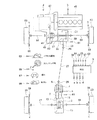
図1は、本発明の実施例1を適用した車両に係りフロント・エンジン、フロント・ドライブ・ベース(FFベース)の4輪駆動車のスケルトン平面図である。
[Four-wheel drive vehicle]
FIG. 1 is a skeleton plan view of a four-wheel drive vehicle of a front engine and a front drive base (FF base) according to a vehicle to which the first embodiment of the present invention is applied.
図1のトルク伝達カップリング1は、スタック脱出制御装置の伝達トルク調節手段として機能し、アクチュエータとして電磁石を用いた電磁クラッチなどにより構成されている。トルク伝達カップリング1は、リヤ・デファレンシャル装置3の入力側において、回転軸5及びドライブ・ピニオン・シャフト7間に介設されている。トルク伝達カップリング1は、後述するコントローラ9による電磁石の通電制御等により締結制御される構成となっている。
The
前記ドライブ・ピニオン・シャフト7のドライブ・ピニオン・ギヤ11は、リヤ・デファレンシャル装置3のリング・ギヤ13に噛み合っている。リヤ・デファレンシャル装置3は、デフ・キャリヤ15に回転自在に支持されている。リヤ・デファレンシャル装置3には、左右のアクスル・シャフト17,19を介して左右の後輪21,23が連動連結されている。
The
前記回転軸5には、ユニバーサル・ジョイント25を介してプロペラ・シャフト27が結合されている。プロペラ・シャフト27には、ユニバーサル・ジョイント29を介して、トランスファ31の出力軸33が結合されている。
A
前記出力軸33の傘歯車35は、伝動軸37の傘歯車39に噛み合っている。伝動軸37は、フロント・デファレンシャル装置41のデフ・ケース43側に設けられ、連動構成されている。
The
前記フロント・デファレンシャル装置41は、エンジン45からトランス・ミッション47を介してリング・ギヤ49にトルクが入力され、回転駆動されるようになっている。フロント・デファレンシャル装置41には、左右のアクスル・シャフト51,53を介して、左右の前輪55,57が連動連結されている。
The front
従って、エンジン45からトランス・ミッション47を介してフロント・デファレンシャル装置41のリング・ギヤ49にトルクが入力されると、一方ではアクスル・シャフト51,53を介して左右の前輪55,57へトルク伝達が行われる。また他方では、デフ・ケース43、伝動軸37、傘歯車39、35を介して出力軸33へトルク伝達が行われる。
Therefore, when torque is input from the
前記出力軸33からは、ユニバーサル・ジョイント29、プロペラ・シャフト27、ユニバーサル・ジョイント25、回転軸5を介してトルク伝達カップリング1へトルクが入力される。
Torque is input from the
前記トルク伝達カップリング1がトルク伝達状態であれば、ドライブ・ピニオン・シャフト7、ドライブ・ピニオン・ギヤ11を介して、リヤ・デファレンシャル装置3のリング・ギヤ13にトルク伝達が行われる。リヤ・デファレンシャル装置3からは、左右のアクスル・シャフト17,19を介して、左右の後輪21,23へトルク伝達が行われる。
If the
従って、トルク伝達カップリング1がトルク伝達状態であるときには、前輪59,61、後輪21,23によって、4輪駆動状態で走行することができる。トルク伝達カップリング1が、トルク伝達状態にないときには、前輪59,61による2輪駆動状態で走行することができる。
Therefore, when the
2輪駆動状態と4輪駆動状態との選択は、運転席のボタン操作等で行うようになっている。選択された「オート・モード」により4輪駆動状態となり、各種センサの検出に基づきコントローラ9により各走行条件下で最適な走行性能を得るための制御が行われる。「2WD」が選択される2輪駆動状態となり、「ロック・モード」が選択されると「オート・モード」よりも出力トルクをアップした制御が行われる。
The selection between the two-wheel drive state and the four-wheel drive state is performed by a button operation on the driver's seat. The four-wheel drive state is set by the selected “auto mode”, and the
さらに、「オート・モード」において、車両のスタック状態が検出されるとトルク伝達カップリング1の「スタック脱出制御」が行われる。「ロック・モード」においても、トルク伝達カップリング1の最大出力値(最大制御出力値)まで制御電流値を印加する余裕があれば、「スタック脱出制御」へ移行させることができる。
Further, when the vehicle stack state is detected in the “auto mode”, “stack escape control” of the
前記コントローラ9には、各種センサの検出値として前後輪55,57,21,23の各車輪回転数59、出力軸33及びドライブ・ピニオン・シャフト7の回転数である前輪後輪側各回転数61、アクセル開度63、ステアリング角(ハンドル角)65、車両に働く横G67、同前後G69が入力されるようになっている。なお、各車輪回転数59と前輪後輪側各回転数61とは、何れか一方を用いることでトルク伝達カップリング1の差回転を算出することができる。これらの入力に基づき、トルク伝達カップリング1の操作力又は操作量a、スロットル開度又は燃料供給量(電気自動車の場合はモータへの電流供給量)b、ブレーキ操作力c、トランス・ミッション47の変速比dの出力が行われる。この出力により「オート・モード」「スタック脱出制御」が行われる。
The
図2は、制御ブロック図である。 FIG. 2 is a control block diagram.
図2のように、コントローラ9に、車両入力信号71として各輪車輪速、前後差回転、車速、アクセル開度、トルク出力値(コントローラ9からの出力指示値)、ハンドル角、前後横Gが入力され、コントローラ9において車両のスタック状態が判断されると制御対象ユニットであるトルク伝達カップリング1の「スタック脱出制御」が行われる。すなわち、コントローラ9は、本実施例において走行状態検出手段及びスタック脱出制御を行う制御手段を構成している。前記車速は、従動輪である後輪21,23の左右回転の平均値から算出している。しかし、種々の既存の検出手段を用いることもできる。
As shown in FIG. 2, the
図3は、オート・モードとスタック脱出制御との切り替えの機能ブロック図である。 FIG. 3 is a functional block diagram of switching between auto mode and stack escape control.
図3のように、各種センサの検出値として各車両入力信号71が演算部73に入力され、演算部73で通常走行時の出力計算が行われ、オート・モード制御部75へ出力される。オート・モード制御部75では、各走行条件下で最適な走行性能を得るための制御出力を行ない、この出力によりトルク伝達カップリング1の「オート・モード」の制御が行われる。
As shown in FIG. 3, each
また、車輪回転数59として右前輪車輪速77及び左前輪車輪速79が駆動輪車輪速演算部81に入力され、同右後輪車輪速83及び左後輪車輪速85が従動輪車輪速演算部87に入力される。駆動輪車輪速演算部81及び従動輪車輪速演算部87での演算結果が前後差回転演算部89に入力され、前後差回転演算部89の演算結果がスタック判断部91へ入力される。スタック判断部91では、前後差回転演算部89の演算結果に加え、駆動輪車輪速演算部81及び従動輪車輪速演算部87からの演算結果とアクセル開度63の検出値とを取り込み、車両のスタック状態を判断し、スタック脱出制御部93へ出力する。スタック脱出制御部93では、通常の「オート・モード」を、強制的に「スタック脱出制御」に切り替え、トルク伝達カップリング1の「スタック脱出制御」を行なう。
Further, the right front wheel speed 77 and the left front wheel speed 79 are input to the driving
「スタック脱出制御」では、「オート・モード」の出力値に定数を掛けて出力し、或いは図4のようなスタック脱出制御用の出力マップを用いて制御することができる。 In “stack exit control”, the output value of “auto mode” is output by multiplying by a constant, or control can be performed using an output map for stack exit control as shown in FIG.
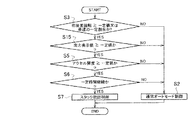
図5は、スタック脱出制御の移行フローチャート、図6は、同解除フローチャートである。 FIG. 5 is a transition flowchart of stack escape control, and FIG. 6 is the release flowchart.
図5のフローチャートでは、駆動輪である前輪55,57がスリップして回転し、従動輪である後輪21,23が非回転又は非回転と見なし得るとき車両がスタック状態であると検出してスタック脱出制御を行う。このフローチャートは、エンジンが始動されると実行され、ステップS1では、「駆動輪車輪速≧一定値」の判断処理が行われる。この判断は、スタック判断部91が、駆動輪車輪速演算部81からの演算結果の入力に基づき行い、「駆動輪車輪速≧一定値」で無ければ(NO)、ステップS2へ移行し、「駆動輪車輪速≧一定値」であれば(YES)、ステップS3へ移行する。
In the flowchart of FIG. 5, when the
ステップS2では、「通常オート・モード制御」が行われる。この制御では、オート・モード制御部75により、各走行条件下で最適な走行性能を得るための制御出力を行ない、この出力によりトルク伝達カップリング1の「オート・モード」の制御が行われる。
In step S2, "normal auto mode control" is performed. In this control, the auto
ステップS3では、「前後差回転≧一定値又は車速の一定割合」の判断処理が行われる。この処理は、従動輪である後輪21,23が一定車輪速以下であることを判断するものである。スタック判断部91が、前後差回転演算部8からの演算結果の入力に基づき行い、「前後差回転≧一定値又は車速の一定割合」であれば(YES)、ステップS4へ移行し、「前後差回転≧一定値又は車速の一定割合」で無ければ(NO)、ステップS2へ移行する。前記車速の一定割合とは、車速に応じて決められた値であり、例えば、車速が100km/hで前輪55,57及び後輪21,23間の差回転ΔNが10rpm、10km/hで差回転ΔNが3rpm等と設定されている。
In step S3, a determination process of “front / rear differential rotation ≧ a constant value or a constant ratio of the vehicle speed” is performed. This process determines that the
ステップS4では、「車速(従動輪車輪速)≦一定値」の判断処理が行われる。この判断は、スタック判断部91が、従動輪車輪速演算部87からの演算結果の入力に基づき行い、「車速(従動輪車輪速)≦一定値」であれば(YES)、ステップS5へ移行し、「車速(従動輪車輪速)≦一定値」で無ければ(NO)、ステップS2へ移行する。
In step S4, a determination process of “vehicle speed (driven wheel speed) ≦ constant value” is performed. This determination is made by the
ステップS5では、「アクセル開度≧一定値」の判断処理が行われる。この判断は、スタック判断部91が、アクセル開度63の入力に基づき行い、「アクセル開度≧一定値」であれば(YES)、ステップS6へ移行し、「アクセル開度≧一定値」で無ければ(NO)、ステップS2へ移行する。「アクセル開度≧一定値」と判断されれば、スタック状態において車両が停止していても、運転者は走行の意志ありと判断することができる。
In step S5, a determination process of “accelerator opening ≧ constant value” is performed. This determination is made by the
ステップS6では、「一定時間継続」の判断処理が行われる。この判断は、コントローラ9のタイマセットにより行われ、タイマの経過時間が設定した一定時間経過すれば(YES)、ステップS7へ移行し、一定時間経過しなければ(NO)、ステップS2へ移行する。このタイマは、ステップS1〜S5の条件が一つでも満たされずステップS2へ移行するときは、タイマ・リセットとなる。
In step S6, a “continuation for a fixed time” determination process is performed. This determination is made by the timer set of the
ステップS7では、「スタック脱出制御」が行われる。この制御では、図4の制御マップを用いるなどしてスタック脱出制御部9によりトルク伝達カップリング1の「スタック脱出制御」が行われる。
In step S7, “stack escape control” is performed. In this control, the “stack escape control” of the
図5のフローチャートにおいては、スタック脱出制御への移行のための条件判断は、少なくともステップS1,S5,S6が存在すればよく、ステップS3,S4は、より高度に制御するために付加されるものである。 In the flowchart of FIG. 5, the condition judgment for the transition to the stack escape control only needs to include at least steps S1, S5, and S6, and steps S3 and S4 are added for more advanced control. It is.
図6のフローチャートの実行では、ステップS11において「スタック脱出制御ON」の判断処理が実行される。この処理において、「スタック脱出制御」が行われていないと判断されると(NO)、ステップS12へ移行し、「スタック脱出制御」が行われていると判断されると(YES)、ステップS13へ移行する。 In the execution of the flowchart of FIG. 6, the determination process of “stack exit control ON” is executed in step S11. In this process, if it is determined that “stack escape control” is not performed (NO), the process proceeds to step S12. If it is determined that “stack escape control” is performed (YES), step S13 is performed. Migrate to
ステップS12では、「通常制御」が行われ、「オート・モード」の制御に戻る。 In step S12, "normal control" is performed, and control returns to "auto mode" control.
ステップS13では、「車速(従動輪車輪速)≦一定値」の判断処理が行われる。この判断は、図5のステップS4と同様に行われ、「車速(従動輪車輪速)≦一定値」であれば(YES)、ステップS14へ移行し、「車速(従動輪車輪速)≦一定値」で無ければ(NO)、ステップS12へ移行する。ステップS14では、「スタック脱出制御」が継続される。 In step S13, a determination process of “vehicle speed (driven wheel speed) ≦ constant value” is performed. This determination is performed in the same manner as in step S4 of FIG. 5. If “vehicle speed (driven wheel speed) ≦ constant value” (YES), the process proceeds to step S14, and “vehicle speed (driven wheel speed) ≦ constant”. If it is not “value” (NO), the process proceeds to step S12. In step S14, “stack escape control” is continued.
[実施例1の効果]
本発明実施例1では、車両のスタック状態を検出したときトルク伝達カップリング1のスタック脱出制御を行わせるため、スタック脱出制御を自動で行わせることができ、スタック状態から的確に脱出を行わせることができる。
[Effect of Example 1]
In the first embodiment of the present invention, the stack escape control of the
前記コントローラ9は、前輪55,57が回転し且つ後輪21,23が非回転又は非回転と見なし得るとき車両がスタック状態であると検出するため、スタック脱出制御を確実に行わせることができる。
Since the
前記コントローラ9は、前輪55,57及び後輪21,23の車輪速とアクセル開度と経過時間とに基づき前輪55,57の車輪速及びアクセル開度が一定値以上で後輪21,23の車輪速が一定値以下である状態が一定時間継続したとき車両がスタック状態であると検出するため、スタック脱出制御をより確実に行わせることができる。
Based on the wheel speeds of the
前記コントローラ9は、前後輪55,57,21,23の差回転が一定値以上又は前後輪55,57,21,23の差回転が車速の一定割合以上であるとき後輪21,23輪の車輪速が一定値以下であると判断するため、スタック脱出制御をより確実に行わせることができる。
When the differential rotation of the front and
前記コントローラ9は、前記トルク伝達カップリング1が締結制御されているとき前後輪55,57,21,23間の回転差が収束しない場合に車両がスタック状態であると検出するため、スタック脱出制御を確実に行わせることができる。
前記コントローラ9は、車速が一定値以上又は後輪21,23の車輪速が一定値以上であるとき車両が非スタック状態であると検出するため、非スタック状態を確実に判断し、「オート・モード」の制御に戻すことができる。
Since the
The
前記トルク伝達カップリング1は、前後輪55,57,21,23の4輪駆動を行うためにボタン操作などにより選択的に通常の「オート・モード」の締結制御が可能であり、コントローラ9は、前記通常の「オート・モード」よりも高い締結力でトルク伝達カップリング1のスタック脱出制御を行わせるため、スタックからの脱出を確実に行わせることができる。
The
図7,図8は、本発明実施例2に係り、図7は、スタック脱出制御の移行フローチャート、図8は、同解除フローチャートである。図7,図8において、図5,図6のフローチャートと同一のステップには、同符号を付して説明する。 FIGS. 7 and 8 relate to the second embodiment of the present invention, FIG. 7 is a transition flowchart of stack escape control, and FIG. 8 is a release flowchart thereof. In FIG. 7 and FIG. 8, the same steps as those in the flowcharts of FIG. 5 and FIG.
図7のフローチャートでは、図5のフローチャートのステップS1を無くし、ステップS4に代えてステップS15とし、トルク伝達カップリング1にトルク出力指示があるにも係わらず前後輪55,57,21,23の回転差が収束しない場合にスタック脱出制御を行わせる。
In the flowchart of FIG. 7, step S1 of the flowchart of FIG. 5 is eliminated, and step S15 is substituted for step S4, and the front and
ステップS15では、「出力指示値≧一定値」の判断処理が行われる。この判断は、スタック判断部91が「オート・モード」におけるトルク伝達カップリング1の締結制御値を出力指示値として行う。「出力指示値≧一定値」であれば(YES)、ステップS5へ移行し、「出力指示値≧一定値」で無ければ(NO)、ステップS2へ移行する。
In step S15, a determination process of “output instruction value ≧ constant value” is performed. This determination is performed by the
すなわち、前記コントローラ9は、前輪55,57及び後輪21,23の車輪速と前記トルク伝達カップリング1の締結制御とアクセル開度と経過時間とに基づき前後輪55,57,21,23の差回転が一定値以上又は前後輪55,57,21,23の差回転が車速の一定割合以上である状態とトルク伝達カップリング1の締結制御値及びアクセル開度が一定値以上である状態とが一定時間継続したとき車両がスタック状態であると検出するため、スタック脱出制御をより確実に行わせることができる。
That is, the
図8のフローチャートでは、図6のフローチャートのステップS13に代えて、ステップS16,S17とした。 In the flowchart of FIG. 8, steps S16 and S17 are used instead of step S13 of the flowchart of FIG.
ステップS16では、「アクセル開度≦一定値」の判断処理が行われる。この判断は、スタック判断部91が、アクセル開度63の入力に基づき行い、「アクセル開度≦一定値」でなければ(NO)、ステップS17へ移行し、「アクセル開度≦一定値」であれば(YES)、ステップS14へ移行する。「アクセル開度≦一定値」と判断されても、スタック状態であるためステップS14へ移行し、「スタック脱出制御」が継続される。
In step S16, a determination process of “accelerator opening ≦ constant value” is performed. This determination is made by the
ステップS17では、「前後差回転≧一定値又は車速の一定割合」の判断処理が行われる。この判断は、図5,図7のステップS3と同様に行われ、「前後差回転≧一定値又は車速の一定割合」であれば(YES)、ステップS14へ移行し、「前後差回転≧一定値又は車速の一定割合」で無ければ(NO)、ステップS12へ移行する。 In step S17, a determination process of “front / rear differential rotation ≧ a constant value or a constant ratio of the vehicle speed” is performed. This determination is performed in the same manner as in step S3 of FIGS. 5 and 7, and if “front / rear differential rotation ≧ fixed value or constant ratio of vehicle speed” (YES), the process proceeds to step S14, and “front / rear differential rotation ≧ fixed”. If it is not “a certain ratio of value or vehicle speed” (NO), the process proceeds to step S12.
すなわち、コントローラ9は、アクセル開度が一定値以上であるとき前輪55,57及び後輪21,23の車輪速に基づき前後輪55,57,21,23の差回転が一定値以下又は前後輪55,57,21,23の差回転が車速の一定割合以下であるとき後輪21,23の車輪速が一定値以上であると車両が非スタック状態であると判断して「オート・モード」の制御に戻すことができる。
That is, the
図9は、本発明の実施例3に係り、フロント・エンジン、リヤ・ドライブの2輪駆動車のスケルトン平面図である。なお、実施例1と対応する構成部分には同符号を付して説明する。 FIG. 9 is a skeleton plan view of a two-wheel drive vehicle of a front engine and a rear drive according to a third embodiment of the present invention. In addition, the same code | symbol is attached | subjected and demonstrated to the component corresponding to Example 1. FIG.
図9では、前輪55A,57Aが従動輪であり、トランス・ミッション47Aの出力軸61Aがユニバーサル・ジョイント29に接続されている。左右駆動輪である後輪21A,23A間の差動を調節可能な差動調節手段として、差動トルク制限クラッチ1Aがリヤ・デファレンシャル装置3に設けられている。差動トルク制限クラッチ1Aは、油圧クラッチにより構成され、コントロール・バルブ95を介して油圧ポンプ97に接続されている。コントロール・バルブ95は、コントローラ9Aにより制御され、「差動制限モード」により、各種センサの検出に基づき各走行条件下で最適な走行性能を得るためにリヤ・デファレンシャル装置3の差動制限トルクの制御が行われる。「ロック・モード」が選択されると「オート・モード」よりも差動制限トルクをアップした制御が行われる。
In FIG. 9, the front wheels 55 </ b> A and 57 </ b> A are driven wheels, and the
さらに、「差動制限モード」において、車両のスタック状態が検出されると差動トルク制限クラッチ1Aの「スタック脱出制御」が行われる。「ロック・モード」においても、差動トルク制限クラッチ1Aの最大出力値まで油圧を掛ける余裕があれば、「スタック脱出制御」へ移行させることができる。 Further, in the “differential limiting mode”, when the stack state of the vehicle is detected, “stack escape control” of the differential torque limiting clutch 1A is performed. Even in the “lock mode”, if there is a margin for applying the hydraulic pressure up to the maximum output value of the differential torque limiting clutch 1A, it is possible to shift to “stack escape control”.
前記コントローラ9Aには、各種センサの検出値として前後輪55A,57A,21A,23Aの各車輪回転数59、アクセル開度63、ステアリング角(ハンドル角)65が入力されるようになっている。これらの入力に基づき、差動トルク制限クラッチ1Aの操作力又は操作量a、スロットル開度又は燃料供給量(電気自動車の場合はモータへの電流供給量)b、ブレーキ操作力cの出力が行われる。この出力により「差動制限モード」「スタック脱出制御」が行われる。
The controller 9A is input with the
本実施例では、車両のスタック状態を検出したとき差動トルク制限クラッチ1Aのスタック脱出制御を行わせるから、スタック脱出制御を自動で行わせることができ、スタック状態から的確に脱出を行わせることができる。 In this embodiment, since the stack escape control of the differential torque limiting clutch 1A is performed when the stack state of the vehicle is detected, the stack escape control can be automatically performed, and the escape from the stack state can be accurately performed. Can do.
前記コントローラ9Aは、左右後輪21A,23Aの一方が回転し且つ他方が非回転又は非回転と見なし得るとき車両がスタック状態であると検出してスタック脱出制御を自動で行わせることができる。
The controller 9A can detect that the vehicle is in a stacked state when one of the left and right
前記コントローラ9Aは、左右後輪21A,23Aの車輪速とアクセル開度と経過時間とに基づき左右後輪21A,23Aの一方の車輪速及びアクセル開度が一定値以上で左右後輪21A,23Aの他方の車輪速が一定値以下である状態が一定時間継続したとき車両がスタック状態であると検出してスタック脱出制御を自動で行わせることができる。
The controller 9A controls the left and right
前記コントローラ9Aは、左右後輪21A,23Aの差回転が一定値以上又は左右後輪21A,23Aの差回転が車速の一定割合以上であるとき左右後輪21A,23Aの他方の車輪速が一定値以下であると判断してスタック脱出制御を自動で行わせることができる。
When the differential rotation of the left and right
前記コントローラ9Aは、前記差動トルク制限クラッチ1Aが制御されているとき左右後輪21A,23A間の回転差が収束しない場合に車両がスタック状態であると検出してスタック脱出制御を自動で行わせることができる。
When the differential torque limiting clutch 1A is being controlled, the controller 9A detects that the vehicle is in a stuck state when the rotational difference between the left and right
前記コントローラ9Aは、左右後輪21A,23Aの車輪速と前記差動トルク制限クラッチ1Aの制御とアクセル開度と経過時間とに基づき左右後輪21A,23Aの差回転が一定値以上又は左右後輪21A,23Aの差回転が車速の一定割合以上、差動トルク制限クラッチ1Aの制御値及びアクセル開度が一定値以上である状態が一定時間継続したとき車両がスタック状態であると検出してスタック脱出制御を自動で行わせることができる。
Based on the wheel speed of the left and right
前記コントローラ9Aは、車速が一定値以上又は左右後輪21A,23Aの車輪速が一定値以上であるとき車両が非スタック状態であると検出して「差動制限モード」に戻ることができる。
The controller 9A can detect that the vehicle is in a non-stacked state when the vehicle speed is equal to or higher than a certain value or the wheel speeds of the left and right
前記コントローラ9Aは、アクセル開度が一定値以上であるとき左右後輪21A,23Aの車輪速に基づき左右後輪21A,23Aの差回転が一定値以下又は左右後輪21A,23Aの差回転が車速の一定割合以下であるとき左右後輪21A,23Aの車輪速が一定値以上であると判断して「差動制限モード」に戻ることができる。
When the accelerator opening is equal to or greater than a certain value, the controller 9A determines that the differential rotation of the left and right
前記差動トルク制限クラッチ1Aは、左右後輪21A,23Aの差動制御を行うために差動制限モードの制御が可能であり、前記コントローラ9Aは、前記差動制限モードよりも高い操作力又は増加した操作量である油圧で前記差動トルク制限クラッチ1Aのスタック脱出制御を行わせることができる。
[その他]
伝達トルク調節手段を操作するアクチュエータは、電磁石に限らず、電動モータ、油圧ピストン、電磁ソレノイドなどの他のアクチュエータを適用することもできる。
The differential torque limiting clutch 1A can control the differential limiting mode in order to perform differential control of the left and right
[Others]
The actuator for operating the transmission torque adjusting means is not limited to an electromagnet, and other actuators such as an electric motor, a hydraulic piston, and an electromagnetic solenoid can also be applied.
車両の駆動輪と従動輪とは、4WD車両の前輪と後輪、又は一般的にFF,FRやMRなどの駆動方式で区別される左右前輪、左右後輪を示すものであり、本願発明のスタック脱出制御装置は、これらの車輪間の伝達トルク調節手段に対して制御を行うことができる。 The driving wheel and the driven wheel of the vehicle indicate a front wheel and a rear wheel of a 4WD vehicle, or left and right front wheels and left and right rear wheels which are generally distinguished by driving methods such as FF, FR, MR, etc. The stack escape control device can control the transmission torque adjusting means between these wheels.
1 トルク伝達カップリング(伝達トルク調節手段)
1A 差動トルク制限クラッチ(差動調節手段)
9,9A コントローラ(走行状態検出手段、制御手段)
21,23 後輪(従動輪)
55,57 前輪(駆動輪)
21A,23A 後輪(駆動輪)
55A,57A 前輪(従動輪)
1 Torque transmission coupling (Transmission torque adjusting means)
1A differential torque limiting clutch (differential adjustment means)
9, 9A controller (running state detection means, control means)
21, 23 Rear wheel (driven wheel)
55,57 Front wheel (drive wheel)
21A, 23A Rear wheel (drive wheel)
55A, 57A Front wheel (driven wheel)
Claims (19)
車両の走行状態を検出する走行状態検出手段と、
前記走行状態検出手段が車両のスタック状態を検出したとき前記伝達トルク調節手段のスタック脱出制御を行わせる制御手段と
を備えたことを特徴とするスタック脱出制御装置。 A transmission torque adjusting means capable of adjusting torque transmission to the driven wheel of the vehicle;
Traveling state detecting means for detecting the traveling state of the vehicle;
A stack escape control device comprising: control means for performing stack escape control of the transmission torque adjusting means when the traveling state detection means detects a stack state of a vehicle.
前記走行状態検出手段は、駆動輪が回転し且つ従動輪が非回転又は非回転と見なし得るとき車両がスタック状態であると検出する
ことを特徴とするスタック脱出制御装置。 The stack escape control device according to claim 1,
The traveling state detecting means detects that the vehicle is in a stacked state when the driving wheel rotates and the driven wheel can be regarded as non-rotating or non-rotating.
前記走行状態検出手段は、駆動輪及び従動輪の車輪速とアクセル開度と経過時間とに基づき駆動輪の車輪速及びアクセル開度が一定値以上で従動輪の車輪速が一定値以下である状態が一定時間継続したとき車両がスタック状態であると検出する
ことを特徴とするスタック脱出制御装置。 The stack escape control device according to claim 1 or 2,
The traveling state detecting means is configured such that the wheel speed and accelerator opening of the driving wheel are equal to or greater than a certain value and the wheel speed of the driven wheel is equal to or less than a certain value based on the wheel speed of the driving wheel and the driven wheel, the accelerator opening, and the elapsed time. A stack escape control device that detects that a vehicle is in a stacked state when the state continues for a certain period of time.
前記走行状態検出手段は、前後輪の差回転が一定値以上又は前後輪の差回転が車速の一定割合以上であるとき従動輪の車輪速が一定値以下であると判断する
ことを特徴とするスタック脱出制御装置。 The stack escape control device according to claim 3,
The traveling state detection means determines that the wheel speed of the driven wheel is equal to or less than a predetermined value when the differential rotation of the front and rear wheels is equal to or greater than a certain value or the differential rotation between the front and rear wheels is equal to or greater than a certain ratio of the vehicle speed. Stack escape control device.
前記走行状態検出手段は、前記伝達トルク調節手段が調節制御されているとき前後輪間の回転差が収束しない場合に車両がスタック状態であると検出する
ことを特徴とするスタック脱出制御装置。 The stack escape control device according to claim 1,
The traveling state detecting means detects that the vehicle is in a stuck state when the rotational difference between the front and rear wheels does not converge when the transmission torque adjusting means is being adjusted and controlled.
前記走行状態検出手段は、駆動輪及び従動輪の車輪速と前記伝達トルク調節手段の制御とアクセル開度と経過時間とに基づき前後輪の差回転が一定値以上又は前後輪の差回転が車速の一定割合以上の状態と伝達トルク調節手段の制御値及びアクセル開度が一定値以上である状態とが一定時間継続したとき車両がスタック状態であると検出する
ことを特徴とするスタック脱出制御装置。 The stack escape control device according to claim 5,
The traveling state detection means is configured such that the differential rotation of the front and rear wheels is a predetermined value or more based on the wheel speed of the driving wheel and the driven wheel, the control of the transmission torque adjusting means, the accelerator opening, and the elapsed time, or the differential rotation of the front and rear wheels is the vehicle speed. A stack escape control device that detects that the vehicle is in a stuck state when a state of a certain ratio or more and a state in which the control value of the transmission torque adjusting means and the accelerator opening are greater than a certain value continue for a certain period of time. .
前記走行状態検出手段は、車速が一定値以上又は従動輪の車輪速が一定値以上であるとき車両が非スタック状態であると検出する
ことを特徴とするスタック脱出制御装置。 The stack escape control device according to claim 1,
The traveling state detecting means detects that the vehicle is in a non-stacked state when the vehicle speed is equal to or higher than a certain value or the wheel speed of the driven wheel is equal to or larger than a certain value.
前記走行状態検出手段は、アクセル開度が一定値以上であるとき駆動輪及び従動輪の車輪速に基づき前後輪の差回転が一定値以下又は前後輪の差回転が車速の一定割合以下であるとき従動輪の車輪速が一定値以上であると判断する
ことを特徴とするスタック脱出制御装置。 The stack escape control device according to claim 7,
The traveling state detecting means is configured such that when the accelerator opening is equal to or greater than a certain value, the differential rotation of the front and rear wheels is equal to or less than a certain value or the differential rotation between the front and rear wheels is equal to or less than a certain ratio of the vehicle speed based on the wheel speeds of the driving wheels and driven wheels. And determining that the wheel speed of the driven wheel is above a certain value.
前記伝達トルク調節手段は、前後輪の4輪駆動を行うために選択的にオート・モードの制御が可能であり、
前記制御手段は、前記オート・モードよりも高い操作力又は増加した操作量で前記伝達トルク調節手段のスタック脱出制御を行わせる
ことを特徴とするスタック脱出制御装置。 The stack escape control device according to claim 1,
The transmission torque adjusting means can selectively control the auto mode in order to perform front and rear wheel four-wheel drive,
The stack escape control device, wherein the control means causes the transfer torque adjusting means to perform stack escape control with a higher operating force or an increased operation amount than in the auto mode.
車両の走行状態を検出する走行状態検出手段と、
前記走行状態検出手段が車両のスタック状態を検出したとき前記差動調節手段のスタック脱出制御を行わせる制御手段と
を備えたことを特徴とするスタック脱出制御装置。 Differential adjustment means capable of adjusting the differential between the left and right drive wheels of the vehicle;
Traveling state detecting means for detecting the traveling state of the vehicle;
A stack escape control device comprising: control means for performing stack escape control of the differential adjustment means when the running state detection means detects a stack state of a vehicle.
前記走行状態検出手段は、左右駆動輪の一方が回転し且つ他方が非回転又は非回転と見なし得るとき車両がスタック状態であると検出する
ことを特徴とするスタック脱出制御装置。 The stack escape control device according to claim 10,
The travel state detection means detects that the vehicle is in a stack state when one of the left and right drive wheels rotates and the other can be regarded as non-rotating or non-rotating.
前記走行状態検出手段は、左右駆動輪の車輪速とアクセル開度と経過時間とに基づき左右駆動輪の一方の車輪速及びアクセル開度が一定値以上で左右駆動輪の他方の車輪速が一定値以下である状態が一定時間継続したとき車両がスタック状態であると検出する
ことを特徴とするスタック脱出制御装置。 The stack escape control device according to claim 10 or 11,
The traveling state detection means is configured such that one wheel speed and accelerator opening of the left and right driving wheels is equal to or greater than a predetermined value and the other wheel speed of the left and right driving wheels is constant based on the wheel speed of the left and right driving wheels, the accelerator opening and the elapsed time. A stack escape control device that detects that a vehicle is in a stuck state when a state that is less than or equal to a value continues for a certain period of time.
前記走行状態検出手段は、左右駆動輪の差回転が一定値以上又は左右駆動輪の差回転が車速の一定割合以上であるとき左右駆動輪の他方の車輪速が一定値以下であると判断する
ことを特徴とするスタック脱出制御装置。 The stack escape control device according to claim 12,
The traveling state detecting means determines that the other wheel speed of the left and right drive wheels is equal to or less than a predetermined value when the differential rotation of the left and right drive wheels is equal to or greater than a certain value or the difference rotation between the left and right drive wheels is equal to or greater than a certain ratio of the vehicle speed. A stack escape control device.
前記走行状態検出手段は、前記差動調節手段が制御されているとき左右駆動輪間の回転差が収束しない場合に車両がスタック状態であると検出する
ことを特徴とするスタック脱出制御装置。 The stack escape control device according to claim 10,
The travel state detection means detects that the vehicle is in a stack state when the difference in rotation between the left and right drive wheels does not converge when the differential adjustment means is being controlled.
前記走行状態検出手段は、左右駆動輪の車輪速と前記差動調節手段の制御とアクセル開度と経過時間とに基づき左右輪の差回転が一定値以上又は左右輪の差回転が車速の一定割合以上、差動制御手段の制御値及びアクセル開度が一定値以上である状態が一定時間継続したとき車両がスタック状態であると検出する
ことを特徴とするスタック脱出制御装置。 The stack escape control device according to claim 14,
The running state detecting means is configured such that the differential rotation of the left and right wheels is a predetermined value or more based on the wheel speed of the left and right drive wheels, the control of the differential adjusting means, the accelerator opening, and the elapsed time, or the differential rotation of the left and right wheels is a constant vehicle speed. A stack escape control device, wherein when the state in which the control value of the differential control means and the accelerator opening are equal to or greater than a certain value continues for a certain time or more, the vehicle is detected to be in a stack state.
前記走行状態検出手段は、車速が一定値以上又は左右駆動輪の車輪速が一定値以上であるとき車両が非スタック状態であると検出する
ことを特徴とするスタック脱出制御装置。 A stack escape control device according to claim 10-15,
The traveling state detecting means detects that the vehicle is in a non-stacked state when the vehicle speed is equal to or higher than a certain value or the wheel speeds of the left and right drive wheels are equal to or larger than a certain value.
前記走行状態検出手段は、アクセル開度が一定値以上であるとき左右駆動輪の車輪速に基づき左右駆動輪の差回転が一定値以下又は左右駆動輪の差回転が車速の一定割合以下であるとき左右駆動輪の車輪速が一定値以上であると判断する
ことを特徴とするスタック脱出制御装置。 The stack escape control device according to claim 16,
When the accelerator opening is equal to or greater than a certain value, the traveling state detection means is configured such that the differential rotation of the left and right drive wheels is less than a certain value based on the wheel speed of the left and right drive wheels or the difference rotation of the left and right drive wheels is less than a certain ratio of the vehicle speed. And determining that the wheel speed of the left and right drive wheels is equal to or greater than a certain value.
前記差動調節手段は、左右駆動輪の差動制御を行うために差動制限モードの制御が可能であり、
前記制御手段は、前記差動制限モードよりも高い操作力又は増加した操作量で前記差動調節手段のスタック脱出制御を行わせる
ことを特徴とするスタック脱出制御装置。 The stack escape control device according to claim 10-17,
The differential adjusting means is capable of controlling a differential limiting mode in order to perform differential control of the left and right drive wheels,
The stack escape control apparatus, wherein the control means causes the differential adjustment means to perform stack escape control with a higher operation force or an increased operation amount than in the differential restriction mode.
前記伝達トルク調節手段は、前記駆動輪及び従動輪間のロックを行うために選択的にロック・モードの制御が可能であり、
前記制御手段は、前記ロック・モードの最大制御出力値まで余裕がある場合に前記伝達トルク調節手段のスタック脱出制御を行わせる
ことを特徴とするスタック脱出制御装置。
The stack escape control device according to any one of claims 1 to 8,
The transmission torque adjusting means is capable of selectively controlling a lock mode in order to lock between the driving wheel and the driven wheel.
The stack escape control device, wherein the control means causes the transfer torque adjusting means to perform stack escape control when there is a margin up to the maximum control output value of the lock mode.
Priority Applications (1)
| Application Number | Priority Date | Filing Date | Title |
|---|---|---|---|
| JP2006020056A JP2007196929A (en) | 2006-01-30 | 2006-01-30 | Stack evacuation controller |
Applications Claiming Priority (1)
| Application Number | Priority Date | Filing Date | Title |
|---|---|---|---|
| JP2006020056A JP2007196929A (en) | 2006-01-30 | 2006-01-30 | Stack evacuation controller |
Publications (1)
| Publication Number | Publication Date |
|---|---|
| JP2007196929A true JP2007196929A (en) | 2007-08-09 |
Family
ID=38451943
Family Applications (1)
| Application Number | Title | Priority Date | Filing Date |
|---|---|---|---|
| JP2006020056A Pending JP2007196929A (en) | 2006-01-30 | 2006-01-30 | Stack evacuation controller |
Country Status (1)
| Country | Link |
|---|---|
| JP (1) | JP2007196929A (en) |
Cited By (3)
| Publication number | Priority date | Publication date | Assignee | Title |
|---|---|---|---|---|
| WO2012102214A1 (en) * | 2011-01-27 | 2012-08-02 | 本田技研工業株式会社 | Driving force control device for four-wheel-drive vehicle |
| JP2018034700A (en) * | 2016-08-31 | 2018-03-08 | 本田技研工業株式会社 | Torque control device of four-wheel drive vehicle |
| JP2021075075A (en) * | 2019-11-05 | 2021-05-20 | トヨタ自動車株式会社 | Driving force control device of vehicle |
-
2006
- 2006-01-30 JP JP2006020056A patent/JP2007196929A/en active Pending
Cited By (8)
| Publication number | Priority date | Publication date | Assignee | Title |
|---|---|---|---|---|
| WO2012102214A1 (en) * | 2011-01-27 | 2012-08-02 | 本田技研工業株式会社 | Driving force control device for four-wheel-drive vehicle |
| GB2501038A (en) * | 2011-01-27 | 2013-10-09 | Honda Motor Co Ltd | Driving force control device for four-wheel-drive vehicle |
| JP5406385B2 (en) * | 2011-01-27 | 2014-02-05 | 本田技研工業株式会社 | Driving force control device for four-wheel drive vehicle |
| US8996267B2 (en) | 2011-01-27 | 2015-03-31 | Honda Motor Co., Ltd. | Driving force control device for four-wheel-drive vehicle |
| GB2501038B (en) * | 2011-01-27 | 2017-10-25 | Honda Motor Co Ltd | Driving force control device for four-wheel-drive vehicle |
| JP2018034700A (en) * | 2016-08-31 | 2018-03-08 | 本田技研工業株式会社 | Torque control device of four-wheel drive vehicle |
| JP2021075075A (en) * | 2019-11-05 | 2021-05-20 | トヨタ自動車株式会社 | Driving force control device of vehicle |
| JP7200910B2 (en) | 2019-11-05 | 2023-01-10 | トヨタ自動車株式会社 | Vehicle driving force control device |
Similar Documents
| Publication | Publication Date | Title |
|---|---|---|
| JP5523869B2 (en) | Vehicle driving state control device | |
| JP2008018832A (en) | Vehicle motion controller | |
| JPH092090A (en) | Front and rear wheel driving vehicle | |
| JPH08300965A (en) | Front and rear wheel drive vehicle | |
| JPS6064033A (en) | Automatic selecting device for four-wheel drive vehicle | |
| JP2007269072A (en) | Working vehicle | |
| JP2007196929A (en) | Stack evacuation controller | |
| US20130110366A1 (en) | Left-right wheel drive force distribution control apparatus for a vehicle | |
| JP2006232094A (en) | Brake control device for vehicle | |
| JP2882474B2 (en) | Power transmission control device for left and right wheels for vehicles | |
| JPS59216732A (en) | Four-wheel-drive vehicle | |
| JP2021025551A (en) | Control apparatus and control method | |
| JP7164044B2 (en) | Driving force distribution method and driving force distribution device for front/rear wheel drive vehicle | |
| JP4754984B2 (en) | Torque distribution control device | |
| JP4462046B2 (en) | Brake control device for vehicle | |
| JP2007154934A (en) | Differential lock controller | |
| US11059533B2 (en) | Vehicle with brake traction control and method for controlling traction of a vehicle | |
| JP2008230465A (en) | Driving force distribution device | |
| JP4087490B2 (en) | Road surface condition detection device | |
| JP5176601B2 (en) | Transmission control device | |
| CN112351904A (en) | Method for controlling a drive system for a motor vehicle axle | |
| JP3603390B2 (en) | Four-wheel drive vehicles | |
| JP2004351945A (en) | Differential control device | |
| JP2001071776A (en) | Differential limitation control method and control system | |
| JP2005306273A (en) | Vehicle driving system |