JP2007196705A - Braking control device for vehicle - Google Patents
Braking control device for vehicle Download PDFInfo
- Publication number
- JP2007196705A JP2007196705A JP2006014077A JP2006014077A JP2007196705A JP 2007196705 A JP2007196705 A JP 2007196705A JP 2006014077 A JP2006014077 A JP 2006014077A JP 2006014077 A JP2006014077 A JP 2006014077A JP 2007196705 A JP2007196705 A JP 2007196705A
- Authority
- JP
- Japan
- Prior art keywords
- braking
- vehicle
- brake
- control
- pressure
- Prior art date
- Legal status (The legal status is an assumption and is not a legal conclusion. Google has not performed a legal analysis and makes no representation as to the accuracy of the status listed.)
- Pending
Links
Images


Abstract
Description
本発明は、乗員が操作するブレーキの操作量に対して、車両に付与する制動力を電子制御する車両用制動制御装置に関するものである。 The present invention relates to a vehicular braking control apparatus that electronically controls a braking force applied to a vehicle with respect to a brake operation amount operated by an occupant.
車両の制動制御装置として、運転者がブレーキペダルを踏み込んだとき、このブレーキペダルから入力されたブレーキ操作量に対して制動装置の制動力、つまり、この制動装置を駆動するホイールシリンダへ供給する油圧を電気的に制御する電子式制動制御装置が知られている。このような制動制御装置としては、例えば、下記特許文献1に記載されたものがある。
As a vehicle braking control device, when a driver depresses a brake pedal, the braking force of the braking device with respect to the brake operation amount input from the brake pedal, that is, the hydraulic pressure supplied to the wheel cylinder that drives the braking device. An electronic braking control device that electrically controls the motor is known. An example of such a braking control device is described in
この特許文献1に記載された車両用制動制御装置は、加速度センサが検出した車両の減速度が、圧力センサが検出したマスタシリンダ圧により設定された値となるように、油圧制御弁を介して各ホイールシリンダの油圧を制御することで、マスタシリンダの踏力に対する応答遅れや踏力の吸収等のため、踏力の小さな変動に応じて制動力が変動することを回避し、制動力のコントロール性を良好にすると共に、車両を滑らかに走行させるものである。
The vehicle brake control device described in
ところで、車両用制動制御装置に適用される油圧ブレーキは、車輪と一体となって回転するディスクをブレーキパッドにより挟み込むことで摩擦を発生させ、この摩擦により制動力を確保している。しかし、ブレーキパッドに取付けられた摩擦材がディスクに押し付けられることで摩耗し、制動力が徐々に低下する。また、油圧ブレーキの長時間の使用によりこの摩擦材が高温となって摩擦係数が低下し、制動力が低下する。 By the way, a hydraulic brake applied to a vehicle brake control device generates friction by sandwiching a disk that rotates integrally with a wheel by a brake pad, and secures a braking force by this friction. However, the friction material attached to the brake pad is worn by being pressed against the disc, and the braking force gradually decreases. In addition, the friction material becomes high temperature by using the hydraulic brake for a long time, the friction coefficient is lowered, and the braking force is lowered.
上述した特許文献1の車両用制動制御装置では、圧力センサにより検出されたマスタシリンダ圧に基づいて目標減速度を決定し、この目標減速度に加速度センサにより検出された車両に作用する実際の減速度が近づくように油圧制御弁を介して各ホイールシリンダの油圧を制御するフィードバック制御を実行している。即ち、この車両用制動制御装置では、ブレーキパッドに取付けられた摩擦材の摩耗や温度変化による制動力の低下が考慮されていない。そのため、従来の油圧ブレーキは、ブレーキパッドに取付けられた摩擦材の使用状況に応じて制動力がばらついてしまい、車両の挙動が安定化するように油圧制御弁の開度を制御することができないおそれがある。
In the vehicle brake control device disclosed in
本発明は、このような問題を解決するためのものであって、ブレーキ効き度合に応じて制動制御の制御量を調整することで車両の走行状態に拘らず適切な制動力の制御を可能とした車両用制動制御装置を提供することを目的とする。 The present invention is for solving such a problem, and it is possible to control the appropriate braking force regardless of the running state of the vehicle by adjusting the amount of braking control according to the degree of braking effectiveness. An object of the present invention is to provide a vehicle braking control device.
上述した課題を解決し、目的を達成するために、本発明の車両用制動制御装置は、乗員が制動操作する操作部材の制動操作量に基づいて目標制動力を設定する目標制動力設定手段と、車両に作用する実際の減速度を検出する減速度検出手段と、前記目標制動力設定手段が設定した目標制動力に応じた目標減速度と前記減速度検出手段が検出した実減速度との偏差に基づいてブレーキ効き度合を判定するブレーキ効き度合判定手段と、前記車両の挙動を検出する車両挙動検出手段と、該車両挙動検出手段が検出した前記車両の挙動が安定するように制動制御の制御量を調整する挙動制御手段と、前記ブレーキ効き度合判定手段の判定結果に基づいて前記制動制御の制御量を補正する制御量補正手段とを具えたことを特徴とするものである。 In order to solve the above-described problems and achieve the object, a vehicle braking control device according to the present invention includes a target braking force setting unit that sets a target braking force based on a braking operation amount of an operating member that is operated by an occupant. A deceleration detection means for detecting an actual deceleration acting on the vehicle, a target deceleration according to a target braking force set by the target braking force setting means, and an actual deceleration detected by the deceleration detection means Brake effectiveness degree judging means for judging the brake effectiveness degree based on the deviation, vehicle behavior detecting means for detecting the behavior of the vehicle, and braking control so as to stabilize the behavior of the vehicle detected by the vehicle behavior detecting means. It is characterized by comprising behavior control means for adjusting the control amount and control amount correction means for correcting the control amount of the braking control based on the determination result of the brake effectiveness degree determination means.
本発明の車両用制動制御装置では、前記ブレーキ効き度合判定手段は、前記ブレーキ効き度合が予め設定された判定値より低いときに前記制御量を増加する一方、前記ブレーキ効き度合が予め設定された判定値より高いときに前記制御量を減少することを特徴としている。 In the vehicle brake control device of the present invention, the brake effectiveness degree determination means increases the control amount when the brake effectiveness degree is lower than a predetermined determination value, while the brake effectiveness degree is preset. The control amount is decreased when the value is higher than the determination value.
本発明の車両用制動制御装置では、車輪の回転を抑制するブレーキを作動させるホイールシリンダと、該ホイールシリンダに油圧を供給する油圧供給源と、前記油圧供給源から前記ホイールシリンダに接続する油圧供給経路に設けられた増圧弁と、前記ホイールシリンダに供給された油圧を排出する油圧排出経路に設けられた減圧弁とを有し、前記制御量補正手段は、前記ブレーキ効き度合判定手段の判定結果に基づいて前記制御量として前記増圧弁及び減圧弁の開度を補正することを特徴としている。 In the vehicle brake control device of the present invention, a wheel cylinder that operates a brake that suppresses rotation of a wheel, a hydraulic pressure supply source that supplies hydraulic pressure to the wheel cylinder, and a hydraulic pressure supply that connects the hydraulic pressure supply source to the wheel cylinder A pressure increasing valve provided in the path and a pressure reducing valve provided in the hydraulic pressure discharge path for discharging the hydraulic pressure supplied to the wheel cylinder, and the control amount correction means is a determination result of the brake effectiveness degree determination means On the basis of the above, the opening amounts of the pressure increasing valve and the pressure reducing valve are corrected as the control amount.
本発明の車両用制動制御装置では、前記制御量補正手段は、前記ブレーキ効き度合判定手段の判定結果に基づいて前記増圧弁及び減圧弁の開度に対する補正係数を設定し、前記増圧弁及び減圧弁の基準開度に前記補正係数を乗算して補正することを特徴としている。 In the vehicle brake control device of the present invention, the control amount correction means sets a correction coefficient for the opening of the pressure increasing valve and the pressure reducing valve based on a determination result of the brake effectiveness degree determining means, and the pressure increasing valve and the pressure reducing valve are set. The correction is performed by multiplying the reference opening of the valve by the correction coefficient.
本発明の車両用制動制御装置では、前記車両挙動検出手段は、車輪速度を検出する車輪速センサを有し、前記挙動制御手段は、該車輪速センサの検出結果に基づいて前記車輪がロックせずに前記車両の挙動が安定するように前記制動制御の制御量を調整するアンチロックブレーキシステムであることを特徴としている。 In the vehicle brake control device of the present invention, the vehicle behavior detecting means has a wheel speed sensor for detecting a wheel speed, and the behavior control means locks the wheel based on a detection result of the wheel speed sensor. The anti-lock brake system adjusts the control amount of the braking control so that the behavior of the vehicle is stabilized.
本発明の車両用制動制御装置によれば、目標制動力に応じた目標減速度と車両に作用する実減速度との偏差に基づいてブレーキ効き度合を判定するブレーキ効き度合判定手段を設ける一方、車両の挙動を検出する車両挙動検出手段と、前記車両の挙動が安定するように制動制御の制御量を調整する挙動制御手段を設けると共に、ブレーキ効き度合判定手段の判定結果に基づいて制動制御の制御量を補正する制御量補正手段を設けたので、挙動制御手段は、車両の挙動が安定するように制動制御の制御量を調整するが、制御量補正手段は、目標減速度と実減速度との偏差に基づいて判定されたブレーキ効き度合に基づいてこの制御量を補正しており、ブレーキ効き度合に応じて制動制御の制御量が調整されることで、車両の走行状態に拘らず適切な制動力の制御を実現することができる。 According to the vehicle brake control device of the present invention, while providing the brake effectiveness degree determination means for determining the brake effectiveness degree based on the deviation between the target deceleration corresponding to the target braking force and the actual deceleration acting on the vehicle, Vehicle behavior detecting means for detecting the behavior of the vehicle and behavior control means for adjusting the control amount of the braking control so as to stabilize the behavior of the vehicle are provided, and braking control based on the determination result of the brake effectiveness degree determining means is provided. Since the control amount correction means for correcting the control amount is provided, the behavior control means adjusts the control amount of the braking control so that the behavior of the vehicle is stabilized, but the control amount correction means has the target deceleration and the actual deceleration. This control amount is corrected based on the braking effectiveness determined based on the deviation from the above, and the braking control amount is adjusted in accordance with the braking effectiveness, so that it is appropriate regardless of the running state of the vehicle. It is possible to realize the control of the Do not braking force.
以下に、本発明に係る車両用制動制御装置の実施例を図面に基づいて詳細に説明する。なお、この実施例によりこの発明が限定されるものではない。 Embodiments of a vehicle brake control device according to the present invention will be described below in detail with reference to the drawings. Note that the present invention is not limited to the embodiments.
図1は、本発明の一実施例に係る車両用制動制御装置を表す概略構成図、図2は、本実施例の車両用制動制御装置における制御ブロックを表す概略図、図3は、本実施例の車両用制動制御装置における制動力制御を表すフローチャート、図4は、本実施例の車両用制動制御装置におけるブレーキ効き判定制御を表すフローチャート、図5は、本実施例の車両用制動制御装置におけるブレーキ効き補正制御を表すフローチャートである。 FIG. 1 is a schematic configuration diagram illustrating a vehicle brake control device according to an embodiment of the present invention, FIG. 2 is a schematic diagram illustrating control blocks in the vehicle brake control device of the present embodiment, and FIG. 4 is a flowchart showing braking force control in the vehicle braking control device of the example, FIG. 4 is a flowchart showing brake effect determination control in the vehicle braking control device of the present embodiment, and FIG. 5 is a vehicle braking control device of the present embodiment. It is a flowchart showing the brake effect correction control in.
本実施例の車両用制動制御装置は、電子制御によって駆動輪の制動力配分を調整するEBD(Electronic Brake force Distribution)制御、駆動輪のロックを防止するABS(Anti−lock Brake System)制御、駆動輪の空転を抑制するTRC(Traction Control System)制御、横滑りを抑制するVSC(Vehicle Stability Control)制御などを可能とした電子制御ブレーキシステムに適用されている。なお、この電子制御ブレーキシステムは、必ずしもEBD制御やABS制御などを実行せず、運転者の操作力に応じた制動力を各駆動輪に付与する通常のブレーキ制御を行うことも可能である。 The vehicle brake control device of the present embodiment includes EBD (Electronic Brake force Distribution) control for adjusting the braking force distribution of the drive wheels by electronic control, ABS (Anti-lock Brake System) control for preventing lock of the drive wheels, and drive The present invention is applied to an electronically controlled brake system that enables TRC (Traction Control System) control that suppresses idling of a wheel, VSC (Vehicle Stability Control) control that suppresses side slip, and the like. Note that this electronically controlled brake system does not necessarily execute EBD control, ABS control, or the like, and can perform normal brake control in which a braking force according to the driver's operating force is applied to each drive wheel.
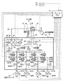
本実施例の車両用制動制御装置は、図1及び図2に示すように、入力部11と、油圧制御部12と、油圧ブレーキ13と、ブレーキ制御部(ブレーキECU)14とから構成されている。即ち、ブレーキペダル21には、運転者によるこのブレーキペダル21の踏み込み操作に応答して作動油を圧送するマスタシリンダ22が接続されると共に、このブレーキペダル21に、その踏み込み量、即ち、ペダルストロークを検出するペダルストロークセンサ23が装着されている。
As shown in FIGS. 1 and 2, the vehicle brake control device of the present embodiment includes an
マスタシリンダ22は、2つの油圧供給配管24,25が連結されており、一方の油圧供給導管24には、通常開放されているシミュレータカット弁26を介してストロークシミュレータ27が接続されている。このストロークシミュレータ27は、運転者によるブレーキペダル21の操作踏力に応じたペダルストロークを発生させるものである。各油圧供給配管24,25には、通常閉弁されているマスタカット弁28,29が装着されており、これらマスタカット弁28,29よりも上流側(マスタシリンダ22側)に、油圧供給配管24,25の油圧を検出するマスタシリンダ圧センサ30,31がそれぞれ装着されている。
The
マスタシリンダ22のリザーバ32には、油圧排出配管33が接続されており、この油圧排出配管33から分岐する油圧供給配管34の途中に、ポンプモータ35により駆動する油圧ポンプ36が配置されると共に、油圧ポンプ36の駆動により昇圧された油圧を貯えるアキュムレータ37が接続されている。また、油圧供給配管34の途中には、アキュムレータ37の内圧を検出するためのアキュムレータ圧センサ38が装着されている。更に、油圧供給配管34と油圧排出配管33との間には、油圧供給配管34内の油圧が高くなった場合に、貯留した作動油をリザーバ32に戻すためのリリーフ弁39が装着されている。
A
油圧供給配管34は4つの油圧供給分岐配管40FR,40FL,40RL,40RRに分岐され、4つの駆動輪(図示略)に配置される油圧ブレーキ13を駆動するホイールシリンダ41FR,41FL,41RL,41RRに接続されている。同様に、油圧排出配管33も4つの油圧排出分岐配管42FR,42FL,42RL,42RRに分岐され、ホイールシリンダ41FR,41FL,41RL,41RRに接続されている。
The
各油圧供給分岐配管40FR,40FL,40RL,40RRの途中の油圧排出分岐配管42FR,42FL,42RL,42RRとの接続部より上流側(油圧ポンプ36側)に、それぞれ電磁式増圧弁43FR,43FL,43RL,43RRが配置され、接続部より下流側(ホイールシリンダ41FR,41FL,41RL,41RR側)に、ホイールシリンダ41FR,41FL,41RL,41RRへ付与される油圧を検出するためのホイールシリンダ圧センサ44FR,44FL,44RL,44RRが配置されている。また、油圧排出分岐配管42FR,42FL,42RL,42RRの途中、つまり、各油圧供給分岐配管40FR,40FL,40RL,40RRとの接続部より下流側(リザーバ32側)に、それぞれ電磁式減圧弁45FR,45FL,45RL,45RRが配置されている。
Electromagnetic pressure increasing valves 43FR, 43FL, 43FR, 43FL, 40FR, 40FL, 40RL, 40RR are connected to the hydraulic discharge branch pipes 42FR, 42FL, 42RL, 42RR on the upstream side (
そして、油圧供給分岐配管40FR,40FL,40RL,40RRは、電磁式増圧弁43FR,43FL,43RL,43RRよりも下流側で、それぞれマスタカット弁28,29を介して油圧供給配管24,25に接続されている。これによりマスタカット弁28,29を介してマスタシリンダ22とホイールシリンダ41FR,41FL,41RL,41RRが接続されることとなる。また、4つの駆動輪には、各駆動輪の回転速度を検出する車輪速センサ46FR,46FL,46RL,46RRが装着されている。
The hydraulic supply branch pipes 40FR, 40FL, 40RL, and 40RR are connected to the
ブレーキECU14は、CPUやメモリ等からなり、格納されているブレーキ制御プログラムを実行することにより制動制御を実行する。即ち、このブレーキECU14には、マスタシリンダ圧センサ30,31が検出した油圧、アキュムレータ圧センサ38が検出した油圧、ホイールシリンダ圧センサ44FR,44FL,44RL,44RRが検出した油圧がそれぞれ入力される。また、ブレーキECU14には、ペダルストロークセンサ23が検出したペダルストローク、各車輪速センサ46FR,46FL,46RL,46RRが検出した車輪速がそれぞれ入力される。そして、ブレーキECU14は、シミュレータカット弁26、マスタカット弁28,29、電磁式増圧弁43FR,43FL,43RL,43RR、電磁式減圧弁45FR,45FL,45RL,45RR、ポンプモータ35、リリーフ弁39を制御可能となっている。
The
従って、通常、マスタカット弁28,29は閉弁され、シミュレータカット弁26は開弁されており、運転者がブレーキペダル21を踏み込み操作すると、マスタシリンダ22はその操作量に応じた油圧を発生する。一方、作動油の一部が油圧供給配管24からシミュレータカット弁26を経由してストロークシミュレータ27へ流れ込むため、ブレーキペダル21の踏力に応じてこのブレーキペダル21の操作量が調整される。即ち、操作踏力に応じたペダル操作量(ペダルストローク)が生成される。なお、このペダルストロークは、ペダルストロークセンサ23により検出されるが、マスタシリンダ圧センサ30,31が検出した油圧からも算出可能であり、それぞれのペダルストロークが一致しない場合には、各センサ23,30,31の異常、あるいはマスタシリンダ22、油圧供給配管24,25の異常と判定する。
Therefore, normally, the master cut
目標制動力設定手段としてのブレーキECU14は、検出したペダルストロークに基づいて目標制動力を設定し、各駆動輪に付与する目標制動力配分を決定し、各ホイールシリンダ41FR,41FL,41RL,41RRへ付与すべき目標油圧の配分を設定する。このとき、アキュムレータ37に所定の油圧が蓄えられているが、アキュムレータ圧センサ38が検出した油圧が規定下限油圧よりも不足している場合には、ポンプモータ35を駆動して油圧ポンプ36を作動して昇圧を行う。一方、油圧が規定上限油圧よりも高すぎる場合には、リリーフ弁39を開弁して作動油をリザーバ32へ解放する。
The
そして、ブレーキECU14は、設定された目標油圧(目標制動力)に基づいて電磁式増圧弁43FR,43FL,43RL,43RR及び電磁式減圧弁45FR,45FL,45RL,45RRを開閉し、各ホイールシリンダ41FR,41FL,41RL,41RRに所定の油圧を付与する。つまり、この各ホイールシリンダ41FR,41FL,41RL,41RRに付与される油圧は、各電磁式増圧弁43FR,43FL,43RL,43RR及び電磁式減圧弁45FR,45FL,45RL,45RRの開度を変更することで調整する。そして、ホイールシリンダ圧センサ44FR,44FL,44RL,44RRが検出したホイールシリンダ圧をフィードバックし、これを目標制動力と比較し、その比較結果に基づいて電磁式増圧弁43FR,43FL,43RL,43RR及び電磁式減圧弁45FR,45FL,45RL,45RRの開度を調整する。
The
例えば、ホイールシリンダ41FRの場合、ブレーキECU14は、ホイールシリンダ圧センサ44FLにより検出されたホイールシリンダ圧を目標油圧と比較し、加圧を要する場合には、減圧弁45FLを閉弁した状態で増圧弁43FLを開く。これによりアキュムレータ37の作動油が油圧供給配管34、増圧弁43FL、油圧供給分岐配管40FLを経由してホイールシリンダ41FLへ供給されることとなり、このホイールシリンダ41FLの油圧が増圧し、制動力が強められる。
For example, in the case of the wheel cylinder 41FR, the
一方、制動力が強すぎて駆動輪がロックしている場合(ABS制御の場合)や、ホイールシリンダ圧センサ44FLが検出したホイールシリンダ圧が目標油圧より高い場合には、ブレーキECU14は、減圧を要すると判定し、増圧弁43FLを閉弁した状態で減圧弁45FLを開弁する。これによりホイールシリンダ41FLへ供給されていた作動油の一部が油圧排出分岐配管42FL、減圧弁45FL、油圧排出配管33を経由してリザーバ32へと戻されることとなり、ホイールシリンダ41FLに付与される油圧が減圧されて制動力が弱められる。
On the other hand, when the braking force is too strong and the driving wheel is locked (in the case of ABS control), or when the wheel cylinder pressure detected by the wheel cylinder pressure sensor 44FL is higher than the target hydraulic pressure, the
そして、増圧または減圧後等のホイールシリンダ圧センサ44FLで検出されたホイールシリンダ圧が目標油圧に略一致している場合、ブレーキECU14は、ホイールシリンダ圧を維持する必要があると判定し、増圧弁43FL及び減圧弁45FLを閉じる。この結果、増圧弁43FL、減圧弁45FLからホイールシリンダ41FL側の油圧供給配管40FLでの作動油の流れが停止することとなり、ホイールシリンダ41FLに付与される油圧が保持される。
If the wheel cylinder pressure detected by the wheel cylinder pressure sensor 44FL after the pressure increase or pressure decrease substantially matches the target hydraulic pressure, the
なお、この油圧ブレーキ13が適用された電子制御ブレーキシステムで油圧制御部12に異常が発生した場合、適切な制動力配分を行うことができない。そこで、油圧制御部12に異常が検出された場合、ブレーキECU14は、マスタカット弁28,29を開弁してシミュレータカット弁26を閉弁し、マスタシリンダ22で生成した油圧を油圧供給配管24,25を経由して直接ホイールシリンダ41FR,41FL,41RL,41RRへと導くことで、手動による制動操作を可能としている。
If an abnormality occurs in the
ところで、上述した本実施例の車両用制動制御装置における油圧ブレーキ13は、図示しないが、車軸と一体になって回転するディスクをブレーキパッドにより両側から締め付け、その摩擦により制動力を確保するものであり、上述したホイールシリンダ41FR,41FL,41RL,41RRによりブレーキパッドを作動させている。この場合、ブレーキパッドに取付けられた摩擦材がディスクに押し付けられることで摩擦力が発生するため、長期の使用によりこの摩擦材が摩耗して摩擦力、つまり、制動力が低下する。また、油圧ブレーキの長時間の使用によりこの摩擦材の温度が高くなるが、摩擦材の温度上昇により摩擦係数が低下するため、制動力が低下する。即ち、油圧ブレーキ13は、ブレーキパッドに取付けられた摩擦材の使用状況に応じて制動力がばらついてしまい、運転者が所望する制動力(減速度)を確保できない場合がある。
By the way, although not shown, the
そこで、本実施例の車両用制動制御装置では、車両に作用する実際の減速度を検出する前後加速度センサ(減速度検出手段)61を設け、ブレーキECU14は、この前後加速度センサ61が検出した車両の前後加速度に基づいて車両に作用する実際の減速度(以下、実減速度)Grを算出する。一方、ブレーキECU14は、ホイールシリンダ圧センサ44FR,44FL,44RL,44RRが検出したホイールシリンダ圧から車両に作用する推定減速度(目標減速度)Geを換算する。そして、実減速度Grと推定減速度Geとの偏差に基づいて、油圧ブレーキ13の効き度合を判定(ブレーキ効き度合判定手段)し、その判定結果に基づいて目標制動力を補正するようにしている。
Therefore, in the vehicle braking control device of this embodiment, a longitudinal acceleration sensor (deceleration detecting means) 61 for detecting an actual deceleration acting on the vehicle is provided, and the
具体的に説明すると、前後加速度センサ61が車両の前後加速度を検出し、ブレーキECU14は、この前後加速度センサ61が検出した前後加速度から車両の実減速度Grを算出する。一方、ホイールシリンダ圧センサ44FR,44FL,44RL,44RRがホイールシリンダ圧を検出し、ブレーキECU14は、このホイールシリンダ圧センサ44FR,44FL,44RL,44RRが検出したホイールシリンダ圧から車両に作用する推定減速度Geを換算する。そして、この実減速度Grから推定減速度Geを減算し、この減算値(偏差)を推定減速度Geで除算し、これを割合として油圧ブレーキ13のブレーキ効き度合Erを算出する。
Er=[(Gr−Ge)/Ge]×100(%)
More specifically, the
Er = [(Gr-Ge) / Ge] × 100 (%)
そして、このブレーキ効き度合Erが予め設定された下限判定値Er1以下だったときには、油圧ブレーキ13の効き度合が悪いと判定し、ブレーキ効き度合Erが上限判定値Er2以上だったときには、油圧ブレーキ13の効き度合が良過ぎると判定する。このとき、ブレーキ効き度合Erが下限判定値Er1より高く、且つ、上限判定値Er2より低い範囲になるように、油圧ブレーキ13の目標制動力、つまり、ホイールシリンダ41FR,41FL,41RL,41RRの目標油圧を増減する。
Then, when the degree Er effectiveness brake seemed set lower judgment value Er 1 below in advance, it determines that the effectiveness degree of the
この場合、ブレーキECU14は、前後加速度センサ61が検出した前後加速度から車両のエンジンブレーキと坂路勾配と転がり抵抗を減算して減速度Grを算出する。
Gr=前後加速度−(エンジンブレーキ+坂路勾配+走行抵抗)
なお、エンジンブレーキは、エンジンの特性により予め設定されており、坂路勾配は、車輪速センサ46FR,46FL,46RL,46RRが検出した車輪速度と前後加速度センサ61が検出した前後加速度とに基づいて推定し、転がり抵抗は、予め設定された車速に対する空気抵抗のマップを用いて車速センサ62が検出した車速に基づいて設定する。
In this case, the
Gr = longitudinal acceleration-(engine brake + slope slope + running resistance)
The engine brake is preset according to engine characteristics, and the slope is estimated based on the wheel speed detected by the wheel speed sensors 46FR, 46FL, 46RL, and 46RR and the longitudinal acceleration detected by the
また、本実施例の車両用制動制御装置は、電子制御によって駆動輪のロックを防止するABSが適用されている。このABSは、本発明の車両挙動検出手段として、上述した車輪速センサ46FR,46FL,46RL,46RRを有し、本発明の挙動制御手段としてのブレーキECU14は、この車輪速センサ46FR,46FL,46RL,46RRの検出結果に基づいて各駆動輪がロックせずに車両の挙動が安定するように制動制御の制御量、つまり、電磁式増圧弁43FR,43FL,43RL,43RR及び電磁式減圧弁45FR,45FL,45RL,45RRの開度を調整している。
In addition, the vehicle braking control apparatus of the present embodiment is applied with ABS that prevents the driving wheels from being locked by electronic control. The ABS has the above-described wheel speed sensors 46FR, 46FL, 46RL, and 46RR as vehicle behavior detecting means of the present invention. The
そして、本実施例の車両用制動制御装置では、前述したように、車両の実減速度Grと推定減速度Geとの偏差に基づいて判定した油圧ブレーキ13の効き度合を判定しており、ABSの制御中には、このブレーキ効き度合の判定結果に基づいて電磁式増圧弁43FR,43FL,43RL,43RR及び電磁式減圧弁45FR,45FL,45RL,45RRの開度を補正している。この場合、ブレーキ効き度合が予め設定された判定値より低いときには、ブレーキ効き度合が良くないとして、制御量を増加、つまり、電磁式増圧弁43FR,43FL,43RL,43RRの開度を大きくする一方、ブレーキ効き度合が予め設定された判定値より高いときには、ブレーキ効き度合が良すぎるとして、制御量を減少、つまり、電磁式減圧弁45FR,45FL,45RL,45RRの開度を大きくする。
In the vehicle brake control device of this embodiment, as described above, the effectiveness of the
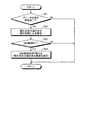
ここで、本実施例の車両用制動制御装置における制動力制御について、図3のフローチャートに基づいて説明する。車両の制動力制御において、図3に示すように、まず、ステップS1では、ストロークセンサ23が検出したペダルストロークを取得し、ステップS2では、ホイールシリンダ圧センサ44FR,44FL,44RL,44RRが検出したホイールシリンダ圧を取得する。次に、ステップS3にて、ペダルストロークに基づいて目標制動力を演算し、目標油圧を設定する。
Here, the braking force control in the vehicle braking control apparatus of the present embodiment will be described based on the flowchart of FIG. In the vehicle braking force control, as shown in FIG. 3, first, in step S1, the pedal stroke detected by the
そして、ステップS4にて、油圧ブレーキ13のブレーキ効き補正を実行する。但し、予め、ブレーキ効き補正値k=1.0と設定されており、後述するブレーキ効き判定処理が完了していないときは、設定した目標油圧を補正することなく、ステップS5にて、目標制動力から各ホイールシリンダ41FR,41FL,41RL,41RRに付与する目標油圧を決定し、この目標油圧に基づいて電磁式増圧弁43FR,43FL,43RL,43RR及び電磁式減圧弁45FR,45FL,45RL,45RRの開度を調整し、各ホイールシリンダ41FR,41FL,41RL,41RRにより油圧ブレーキ13を作動させる。このとき、ホイールシリンダ圧をフィードバックし、目標油圧と一致するように制御する。
In step S4, the brake effect correction of the
そして、ステップS6にて、油圧ブレーキ13のブレーキ効き判定を実行する。本実施例の車両用制動制御装置におけるブレーキ効き判定制御において、図4に示すように、ステップS11では、前後加速度センサ61が検出した車両の前後加速度を取得し、ステップS12では、車輪速センサ46FR,46FL,46RL,46RRが検出した車輪速度を取得し、ステップS13では、車速センサ62が検出した車速を取得し、ステップS14では、ホイールシリンダ圧センサ44FR,44FL,44RL,44RRが検出したホイールシリンダ圧を取得する。
In step S6, the brake effectiveness determination of the
そして、ステップS15では、下記数式に基づいて油圧ブレーキ13のブレーキ効き度合Erを算出する。
Er=[(Gr−Ge)/Ge]×100(%)
続いて、ステップS16では、このブレーキ効き度合Erが予め設定された下限判定値Er1より大きく、且つ、上限判定値Er2より小さい範囲にあるかどうかを判定する。つまり、油圧ブレーキ13にて、ブレーキパッドに取付けられた摩擦材の使用状況(摩耗や温度上昇による摩擦係数μの低下)により制動力が変動しているかどうかを判定する。
In step S15, the braking effectiveness degree Er of the
Er = [(Gr-Ge) / Ge] × 100 (%)
Subsequently, in step S16, it is determined whether or not the braking effectiveness degree Er is in a range larger than a preset lower limit determination value Er 1 and smaller than an upper limit determination value Er 2 . That is, in the
このステップS16にて、ブレーキ効き度合Erが下限判定値Er1と上限判定値Er2との範囲にあると判定されたら、油圧ブレーキ13の効き度合が良いと判定し、ブレーキ効き補正値kを変更せずに前回のものを保持する。一方、ブレーキ効き度合Erが下限判定値Er1と上限判定値Er2との範囲にないと判定されたら、ステップS17に移行し、ここで、ブレーキ効き度合Erが下限判定値Er1と上限判定値Er2との範囲に入るように、具体的には、Er=0となるようにブレーキ効き補正値kを変更する。この場合、ブレーキ効き度合Erが下限判定値Er1より小さいときには、ブレーキ効き補正値kが大きくなる方向に変更し、ブレーキ効き度合Erが上限判定値Er2より大きいときは、ブレーキ効き補正値kが小さくなる方向に変更する。
At step S16, When the brake effectiveness degree Er is determined to be in the range of the lower limit determination value Er 1 and the upper limit determination value Er 2, it determines that effectiveness degree of the
このように油圧ブレーキ13の効き度合が適切でなく、ブレーキ効き補正値kが新たに設定されると、前述した車両の制動力制御におけるステップS4にて、目標制動力にブレーキ効き補正値kが乗算されることで補正され、ステップS5にて、補正された目標制動力に基づいて目標油圧が設定され、この目標油圧に基づいて電磁式増圧弁43FR,43FL,43RL,43RR及び電磁式減圧弁45FR,45FL,45RL,45RRの開度が調整されることとなり、油圧ブレーキ13の効き度合が良好となる。
As described above, when the effectiveness of the
また、上述したように、油圧ブレーキ13の効き度合が判定されると、この判定結果をABS制御に適用する。即ち、本実施例の車両用制動制御装置におけるブレーキ効き補正制御において、図5に示すように、ステップS21では、ブレーキ効き判定処理が完了したかどうかを判定する。ここで、ブレーキ効き判定処理が完了していないと判定されたら、何もしないでこのルーチンを抜ける。
As described above, when the effectiveness of the
一方、ステップS21にて、ブレーキ効き判定処理が完了したと判定されたら、既にブレーキ効き判定結果、つまり、ブレーキ効き度合Erが算出されていると判断し、ステップS22にて、電磁式増圧弁43FR,43FL,43RL,43RR及び電磁式減圧弁45FR,45FL,45RL,45RRの基準開度に対する制御量補正係数k1,k2を演算する。この場合、前述したブレーキ効き補正値kと同様に、ブレーキ効き度合Erが下限判定値Er1より小さいときには、制御量補正係数k1,k2が大きくなる方向に設定し、ブレーキ効き度合Erが上限判定値Er2より大きいときは、制御量補正係数k1,k2が小さくなる方向に設定する。 On the other hand, if it is determined in step S21 that the braking effectiveness determination process has been completed, it is determined that the braking effectiveness determination result, that is, the braking effectiveness degree Er has already been calculated, and in step S22, the electromagnetic pressure increasing valve 43FR is determined. calculates 43FL, 43RL, 43RR and the solenoid pressure reducing valves 45FR, 45FL, 45RL, the control amount correction coefficient k 1, k 2 for the reference opening for 45RR. In this case, similarly to the correction value k effectiveness brakes described above, when the brake effectiveness degree Er is less than the lower judgment value Er 1 is set to a direction control amount correction coefficient k 1, k 2 increases, brake effectiveness degree Er is when the upper limit is greater than the determination value Er 2 is set in the direction in which the control amount correction coefficient k 1, k 2 becomes small.
そして、ステップS22にて、電磁式増圧弁43FR,43FL,43RL,43RR及び電磁式減圧弁45FR,45FL,45RL,45RRの制御量補正係数k1,k2が設定されたら、ステップS23にて、ABS制御中であるかどうかを判定する。即ち、ブレーキECU14が、車輪速センサ46FR,46FL,46RL,46RRの検出結果に基づいて各駆動輪がロックせずに車両の挙動が安定するように電磁式増圧弁43FR,43FL,43RL,43RR及び電磁式減圧弁45FR,45FL,45RL,45RRの開度を調整しているかどうかを判定する。
When the control amount correction coefficients k 1 and k 2 for the electromagnetic pressure increasing valves 43FR, 43FL, 43RL, and 43RR and the electromagnetic pressure reducing valves 45FR, 45FL, 45RL, and 45RR are set in step S22, in step S23. It is determined whether ABS control is in progress. That is, the
ここで、ABS制御中でないと判定されたら、何もしないでこのルーチンを抜ける。一方、ABS制御中であると判定されたら、ステップS24にて、ABS制御を切り替える。つまり、電磁式増圧弁43FR,43FL,43RL,43RRの基準開度に制御量補正係数k1を乗算して補正すると共に、電磁式減圧弁45FR,45FL,45RL,45RRの基準開度に制御量補正係数k2を乗算して補正する。 Here, if it is determined that the ABS control is not being performed, this routine is exited without doing anything. On the other hand, if it is determined that the ABS control is being performed, the ABS control is switched in step S24. In other words, electromagnetic booster valves 43FR, 43FL, 43RL, is corrected by multiplying the control amount correction coefficient k 1 to the reference opening degree of 43RR, controlled variable electromagnetic pressure reducing valves 45FR, 45FL, 45RL, the reference opening of 45RR Correction is performed by multiplying the correction coefficient k 2 .
従って、ABS制御中には、ブレーキ効き度合に基づいて電磁式増圧弁43FR,43FL,43RL,43RR及び電磁式減圧弁45FR,45FL,45RL,45RRの開度が補正されることで、車両の走行状態に拘らず適切な制動力の制御が可能となる。 Therefore, during ABS control, the opening of the electromagnetic pressure increasing valves 43FR, 43FL, 43RL, 43RR and the electromagnetic pressure reducing valves 45FR, 45FL, 45RL, 45RR is corrected based on the degree of braking effectiveness, so that the vehicle travels. Appropriate braking force control is possible regardless of the state.
このように本実施例の車両用制動制御装置にあっては、前後加速度センサ61が検出した実減速度Grと、ホイールシリンダ圧センサ44FR,44FL,44RL,44RRが検出したホイールシリンダ圧から算出した推定減速度Geとの偏差に基づいて、油圧ブレーキ13の効き度合を判定し、ブレーキECU14は、車輪速センサ46FR,46FL,46RL,46RRの検出結果に基づいて各駆動輪がロックせずに車両の挙動が安定するように電磁式増圧弁43FR,43FL,43RL,43RR及び電磁式減圧弁45FR,45FL,45RL,45RRの基準開度を設定すると共に、油圧ブレーキ13の効き度合に基づいてこの基準開度を補正するようにしている。
As described above, in the vehicle braking control device of this embodiment, the actual deceleration Gr detected by the
従って、ブレーキECU14は、車両の挙動が安定するように電磁式増圧弁43FR,43FL,43RL,43RR及び電磁式減圧弁45FR,45FL,45RL,45RRの基準開度を設定するが、この基準開度は、目標減速度Geと実減速度Grとの偏差に基づいて判定されたブレーキ効き度合に基づいて補正されるため、ブレーキ効き度合に応じたABS制御を行うことができ、車両の走行状態に拘らず適切な制動力の制御を実現することができる。
Therefore, the
また、本実施例の車両用制動制御装置では、前後加速度センサ61が検出した前後加速度から車両の実減速度Grを算出する一方、ホイールシリンダ圧センサ44FR,44FL,44RL,44RRが検出したホイールシリンダ圧から車両に作用する推定減速度Geを算出し、この実減速度Grから推定減速度Geを減算し、この減算値(偏差)を推定減速度Geで除算し、これを割合として油圧ブレーキ13のブレーキ効き度合Erを算出しており、高精度なブレーキ効き判定を実行することができる。
Further, in the vehicle brake control device of the present embodiment, the actual deceleration Gr of the vehicle is calculated from the longitudinal acceleration detected by the
更に、本実施例の車両用制動制御装置では、ブレーキ効き判定結果に基づいて、電磁式増圧弁43FR,43FL,43RL,43RR及び電磁式減圧弁45FR,45FL,45RL,45RRの基準開度に対する制御量補正係数k1,k2を演算し、ブレーキ効き度合Erが良くないときには、制御量補正係数k1,k2が大きくなる方向に設定し、ブレーキ効き度合Erが良すぎるときには、制御量補正係数k1,k2が小さくなる方向に設定している。従って、ブレーキ効き度合Erに応じた適切な電磁式増圧弁43FR,43FL,43RL,43RR及び電磁式減圧弁45FR,45FL,45RL,45RRの開度に補正することができる。 Furthermore, in the vehicle brake control device of the present embodiment, the control for the reference opening of the electromagnetic pressure increasing valves 43FR, 43FL, 43RL, 43RR and the electromagnetic pressure reducing valves 45FR, 45FL, 45RL, 45RR is performed based on the brake effectiveness determination result. The amount correction coefficients k 1 and k 2 are calculated, and when the braking effectiveness degree Er is not good, the control amount correction coefficients k 1 and k 2 are set so as to increase, and when the braking effectiveness degree Er is too good, the control amount correction is performed. The coefficients k 1 and k 2 are set to be smaller. Therefore, it is possible to correct the opening of the appropriate electromagnetic pressure increasing valves 43FR, 43FL, 43RL, 43RR and the electromagnetic pressure reducing valves 45FR, 45FL, 45RL, 45RR according to the braking effectiveness degree Er.
そして、本実施例では、本発明の車両用制動制御装置をABSに適用しており、より安定化した車両の挙動制御を可能とすることができる。 In this embodiment, the vehicle braking control device of the present invention is applied to the ABS, and the vehicle behavior control can be made more stable.
なお、上述した実施例では、制動制御の制御量を、油圧ブレーキ13のホイールシリンダ41FR,41FL,41RL,41RRに対する油圧給排量(増圧量及び減圧量)としたが、増圧勾配及び減圧勾配であってもよい。また、この場合、電磁式増圧弁43FR,43FL,43RL,43RR及び電磁式減圧弁45FR,45FL,45RL,45RRを有するABSとしたが、これに代えて増圧及び減圧が可能な電磁式アクチュエータとしてもよい。
In the above-described embodiment, the control amount of the braking control is the hydraulic supply / discharge amount (the pressure increase amount and the pressure decrease amount) with respect to the wheel cylinders 41FR, 41FL, 41RL, 41RR of the
また、上述した実施例では、前後加速度センサ61が検出した車両の前後加速度に基づいて実減速度Grを算出する一方、ホイールシリンダ圧センサ44FR,44FL,44RL,44RRが検出したホイールシリンダ圧から車両に作用する推定減速度Geを換算し、実減速度Grと推定減速度Geとの偏差に基づいて、油圧ブレーキ13の効き度合を判定するようにしたが、この構成に限定されるものではない。即ち、マスタシリンダ圧センサ30,31が検出したマスタシリンダ圧から車両に作用する推定減速度Geを求めたり、ストロークセンサ23が検出したペダルストロークに基づいて設定した目標制動力(目標油圧)から車両に作用する推定減速度Geを求めてもよい。
In the above-described embodiment, the actual deceleration Gr is calculated based on the longitudinal acceleration of the vehicle detected by the
また、上述した実施例では、本発明の車両用制動制御装置をABS制御に適用して説明したが、このシステムに限らず、EBD制御、TRC制御、VSC制御などに適用してもよく、この場合であっても、上述した実施例と同様の作用効果を奏することができる。 In the above-described embodiment, the vehicular braking control apparatus of the present invention is applied to ABS control. However, the present invention is not limited to this system, and may be applied to EBD control, TRC control, VSC control, etc. Even if it is a case, there can exist the same effect as the Example mentioned above.
更に、上述した実施例では、目標油圧をホイールシリンダ41FR,41FL,41RL,41RRに付与して油圧ブレーキ13を作動させたとき、ホイールシリンダ圧をフィードバックし、目標油圧と一致するように制御したが、本発明の車両用制動制御装置は、このフィードバック制御を実施しなくてもよく、ブレーキ効き判定の学習制御により高精度な制動制御を可能とすることができる。
Further, in the above-described embodiment, when the target hydraulic pressure is applied to the wheel cylinders 41FR, 41FL, 41RL, 41RR and the
以上のように、本発明に係る車両用制動制御装置は、ブレーキ効き度合に基づいて車両の挙動を安定化させる制動制御の制御量を補正するものであり、いずれの種類の制動制御装置に用いても好適である。 As described above, the vehicle brake control device according to the present invention corrects the control amount of the brake control that stabilizes the behavior of the vehicle based on the degree of braking effectiveness, and is used for any type of brake control device. Is also suitable.
11 入力部
12 油圧制御部
13 油圧ブレーキ
14 ブレーキECU(目標制動力設定手段、ブレーキ効き度合判定手段、挙動制御手段、制御量補正手段)
21 ブレーキペダル
22 マスタシリンダ
23 ストロークセンサ
30,31 マスタシリンダ圧センサ
41FR,41FL,41RL,41RR ホイールシリンダ
43FR,43FL,43RL,43RR 電磁式増圧弁
44FR,44FL,44RL,44RR ホイールシリンダ圧センサ
45FR,45FL,45RL,45RR 電磁式減圧弁
46FR,46FL,46RL,46RR 車輪速センサ(車両挙動検出手段)
61 前後加速度センサ
62 車速センサ
DESCRIPTION OF
21
61
Claims (5)
Priority Applications (1)
| Application Number | Priority Date | Filing Date | Title |
|---|---|---|---|
| JP2006014077A JP2007196705A (en) | 2006-01-23 | 2006-01-23 | Braking control device for vehicle |
Applications Claiming Priority (1)
| Application Number | Priority Date | Filing Date | Title |
|---|---|---|---|
| JP2006014077A JP2007196705A (en) | 2006-01-23 | 2006-01-23 | Braking control device for vehicle |
Publications (2)
| Publication Number | Publication Date |
|---|---|
| JP2007196705A true JP2007196705A (en) | 2007-08-09 |
| JP2007196705A5 JP2007196705A5 (en) | 2008-05-22 |
Family
ID=38451761
Family Applications (1)
| Application Number | Title | Priority Date | Filing Date |
|---|---|---|---|
| JP2006014077A Pending JP2007196705A (en) | 2006-01-23 | 2006-01-23 | Braking control device for vehicle |
Country Status (1)
| Country | Link |
|---|---|
| JP (1) | JP2007196705A (en) |
Cited By (9)
| Publication number | Priority date | Publication date | Assignee | Title |
|---|---|---|---|---|
| JP2011143884A (en) * | 2010-01-18 | 2011-07-28 | Advics Co Ltd | Wheel braking force estimating device and motion controller of vehicle having the device |
| JP2011145266A (en) * | 2010-01-18 | 2011-07-28 | Advics Co Ltd | Apparatus for estimation of vehicle specification with device for correcting anteroposterior acceleration of vehicle, and device for correcting anteroposterior acceleration of vehicle |
| JP2013180600A (en) * | 2012-02-29 | 2013-09-12 | Advics Co Ltd | Device and method for brake control of vehicle |
| JP2017517438A (en) * | 2014-06-09 | 2017-06-29 | コンチネンタル オートモーティブ システムズ インコーポレイテッドContinental Automotive Systems, Inc. | Trailer brake system with optimized trailer gain |
| JP2018144559A (en) * | 2017-03-02 | 2018-09-20 | 株式会社アドヴィックス | Brake control device |
| JP2019519430A (en) * | 2016-06-15 | 2019-07-11 | ボルボトラックコーポレーション | Vehicle wheel control device |
| JP2022519250A (en) * | 2019-02-07 | 2022-03-22 | ロベルト・ボッシュ・ゲゼルシャフト・ミト・ベシュレンクテル・ハフツング | Powered vehicle brake device by hydraulic pressure |
| CN114938644A (en) * | 2020-01-15 | 2022-08-23 | 沃尔沃卡车集团 | Method for moving a heavy vehicle |
| WO2023276962A1 (en) * | 2021-06-29 | 2023-01-05 | 株式会社アドヴィックス | Control device |
Citations (8)
| Publication number | Priority date | Publication date | Assignee | Title |
|---|---|---|---|---|
| JPH0227146A (en) * | 1988-07-15 | 1990-01-29 | Mazda Motor Corp | Device for controlling intake air quantity of engine |
| JPH04266560A (en) * | 1991-02-22 | 1992-09-22 | Nissan Motor Co Ltd | Integrated control brake device |
| JPH05262212A (en) * | 1992-03-18 | 1993-10-12 | Toyota Motor Corp | Vehicle braking method |
| JPH09323634A (en) * | 1996-06-04 | 1997-12-16 | Toyota Motor Corp | Master cylinder pressure estimating device and wheel cylinder pressure estimating device using it |
| JPH10250558A (en) * | 1997-03-11 | 1998-09-22 | Tokico Ltd | Brake control device |
| JPH11189138A (en) * | 1997-12-25 | 1999-07-13 | Aisin Seiki Co Ltd | Braking control device of vehicle |
| JP2004090899A (en) * | 2002-09-04 | 2004-03-25 | Advics:Kk | Brake alarm device for vehicle |
| JP2005329937A (en) * | 2004-04-23 | 2005-12-02 | Nissan Motor Co Ltd | Braking force control device of vehicle |
-
2006
- 2006-01-23 JP JP2006014077A patent/JP2007196705A/en active Pending
Patent Citations (8)
| Publication number | Priority date | Publication date | Assignee | Title |
|---|---|---|---|---|
| JPH0227146A (en) * | 1988-07-15 | 1990-01-29 | Mazda Motor Corp | Device for controlling intake air quantity of engine |
| JPH04266560A (en) * | 1991-02-22 | 1992-09-22 | Nissan Motor Co Ltd | Integrated control brake device |
| JPH05262212A (en) * | 1992-03-18 | 1993-10-12 | Toyota Motor Corp | Vehicle braking method |
| JPH09323634A (en) * | 1996-06-04 | 1997-12-16 | Toyota Motor Corp | Master cylinder pressure estimating device and wheel cylinder pressure estimating device using it |
| JPH10250558A (en) * | 1997-03-11 | 1998-09-22 | Tokico Ltd | Brake control device |
| JPH11189138A (en) * | 1997-12-25 | 1999-07-13 | Aisin Seiki Co Ltd | Braking control device of vehicle |
| JP2004090899A (en) * | 2002-09-04 | 2004-03-25 | Advics:Kk | Brake alarm device for vehicle |
| JP2005329937A (en) * | 2004-04-23 | 2005-12-02 | Nissan Motor Co Ltd | Braking force control device of vehicle |
Cited By (12)
| Publication number | Priority date | Publication date | Assignee | Title |
|---|---|---|---|---|
| JP2011143884A (en) * | 2010-01-18 | 2011-07-28 | Advics Co Ltd | Wheel braking force estimating device and motion controller of vehicle having the device |
| JP2011145266A (en) * | 2010-01-18 | 2011-07-28 | Advics Co Ltd | Apparatus for estimation of vehicle specification with device for correcting anteroposterior acceleration of vehicle, and device for correcting anteroposterior acceleration of vehicle |
| JP2013180600A (en) * | 2012-02-29 | 2013-09-12 | Advics Co Ltd | Device and method for brake control of vehicle |
| JP2017517438A (en) * | 2014-06-09 | 2017-06-29 | コンチネンタル オートモーティブ システムズ インコーポレイテッドContinental Automotive Systems, Inc. | Trailer brake system with optimized trailer gain |
| JP2019519430A (en) * | 2016-06-15 | 2019-07-11 | ボルボトラックコーポレーション | Vehicle wheel control device |
| US10974705B2 (en) | 2016-06-15 | 2021-04-13 | Volvo Truck Corporation | Wheel controller for a vehicle |
| JP2018144559A (en) * | 2017-03-02 | 2018-09-20 | 株式会社アドヴィックス | Brake control device |
| JP2022519250A (en) * | 2019-02-07 | 2022-03-22 | ロベルト・ボッシュ・ゲゼルシャフト・ミト・ベシュレンクテル・ハフツング | Powered vehicle brake device by hydraulic pressure |
| JP7329606B2 (en) | 2019-02-07 | 2023-08-18 | ロベルト・ボッシュ・ゲゼルシャフト・ミト・ベシュレンクテル・ハフツング | Electro-hydraulic powered vehicle braking system |
| CN114938644A (en) * | 2020-01-15 | 2022-08-23 | 沃尔沃卡车集团 | Method for moving a heavy vehicle |
| WO2023276962A1 (en) * | 2021-06-29 | 2023-01-05 | 株式会社アドヴィックス | Control device |
| DE112022003282T5 (en) | 2021-06-29 | 2024-04-11 | Advics Co., Ltd. | Control device |
Similar Documents
| Publication | Publication Date | Title |
|---|---|---|
| US8788172B2 (en) | Method and device for controlling an electrohydraulic braking system for motor vehicles | |
| JP2007196705A (en) | Braking control device for vehicle | |
| JP4412400B2 (en) | Vehicle behavior control device | |
| US10676074B2 (en) | Brake fluid pressure control apparatus for vehicle | |
| US8506022B2 (en) | Brake apparatus and method for controlling the brake apparatus | |
| US8794716B2 (en) | Brake fluid pressure control apparatus for vehicle | |
| JP4497230B2 (en) | BRAKE CONTROL DEVICE AND BRAKE CONTROL METHOD | |
| EP2313299B1 (en) | Brake controller, brake control system, and brake control method | |
| JP4396589B2 (en) | Brake control device for vehicle | |
| JP5018093B2 (en) | Braking control device | |
| WO2018079696A1 (en) | Brake device for vehicle | |
| JP5035171B2 (en) | Brake control device | |
| JP4935760B2 (en) | Brake control device | |
| US7513578B2 (en) | Brake system control apparatus | |
| US20220314812A1 (en) | Braking control device for vehicle | |
| JP6701656B2 (en) | Vehicle braking control device | |
| JP4487917B2 (en) | Brake control device for vehicle | |
| KR102231112B1 (en) | Active hydraulic booster system in vehice and control method thereof | |
| JP5209589B2 (en) | Brake hydraulic pressure control device for vehicles | |
| JP5119009B2 (en) | Vehicle control device | |
| JP4670655B2 (en) | Brake control device for vehicle | |
| JP5233597B2 (en) | Brake control device | |
| JP2007230420A (en) | Brake control device | |
| JP5098716B2 (en) | Brake control device | |
| JP2010006317A (en) | Vehicle control device |
Legal Events
| Date | Code | Title | Description |
|---|---|---|---|
| A521 | Written amendment |
Effective date: 20080407 Free format text: JAPANESE INTERMEDIATE CODE: A523 |
|
| A621 | Written request for application examination |
Effective date: 20080407 Free format text: JAPANESE INTERMEDIATE CODE: A621 |
|
| A977 | Report on retrieval |
Effective date: 20100225 Free format text: JAPANESE INTERMEDIATE CODE: A971007 |
|
| A131 | Notification of reasons for refusal |
Effective date: 20100323 Free format text: JAPANESE INTERMEDIATE CODE: A131 |
|
| A02 | Decision of refusal |
Free format text: JAPANESE INTERMEDIATE CODE: A02 Effective date: 20101005 |