JP2007193202A - Iris device - Google Patents

Iris device Download PDF

Info

Publication number
JP2007193202A
JP2007193202A JP2006012612A JP2006012612A JP2007193202A JP 2007193202 A JP2007193202 A JP 2007193202A JP 2006012612 A JP2006012612 A JP 2006012612A JP 2006012612 A JP2006012612 A JP 2006012612A JP 2007193202 A JP2007193202 A JP 2007193202A
Authority
JP
Japan
Prior art keywords
iris
blade
iris blade
movable output
displacement
Prior art date
Legal status (The legal status is an assumption and is not a legal conclusion. Google has not performed a legal analysis and makes no representation as to the accuracy of the status listed.)
Pending
Application number
JP2006012612A
Other languages
Japanese (ja)
Inventor
Tetsuo Takahashi
哲郎 高橋
Motoshige Midorikawa
基重 翠川
Current Assignee (The listed assignees may be inaccurate. Google has not performed a legal analysis and makes no representation or warranty as to the accuracy of the list.)
Cosina Co Ltd
Original Assignee
Cosina Co Ltd
Priority date (The priority date is an assumption and is not a legal conclusion. Google has not performed a legal analysis and makes no representation as to the accuracy of the date listed.)
Filing date
Publication date
Application filed by Cosina Co Ltd filed Critical Cosina Co Ltd
Priority to JP2006012612A priority Critical patent/JP2007193202A/en
Publication of JP2007193202A publication Critical patent/JP2007193202A/en
Pending legal-status Critical Current

Links

Images

Abstract

<P>PROBLEM TO BE SOLVED: To achieve high response, high speed, and high precision demanded when the degree of opening of the iris blades is repeatedly controlled in a short period. <P>SOLUTION: The iris device 1 for varying a quantity of passing light by being disposed in the optical path Rc of an optical system C includes: an iris blade section 2 having the first and second iris blades 2a and 2b disposed so as to be freely displaced in a rectilinear direction Fs; a driving section 3 having a linear motor 4 that directly transmits an amount of displacement of a movable output section 4o to the first iris blade 2a; and a displacement transmission mechanism 5 that transmits the amount of displacement of the movable output section 4o to the second iris blade 2b and displaces the second iris blade 2b in such a direction as to be symmetrical relative to the first iris blade 2a. <P>COPYRIGHT: (C)2007,JPO&INPIT

Description

本発明は、プロジェクタ等における光学系の光路に配設することにより通過する光量を可変するアイリス装置に関する。   The present invention relates to an iris device that varies the amount of light passing therethrough by being disposed in an optical path of an optical system in a projector or the like.

一般に、スクリーンに画像を投影するプロジェクタは知られており、この種のプロジェクタには、通常、光学系の光路に配設して通過する光量を可変するアイリス装置を備えている。ところで、近時、プロジェクタでは、明るい画像はより明るく、かつ暗い画像はより暗くなるように、アイリス装置を利用してコントラストを高めることが行われており、この目的で用いるアイリス装置は、画像フレーム(毎秒60回)毎の短い周期によりアイリス羽根の開度制御が繰り返されることからアイリス羽根の制御に対する高応答化,高速化及び高精度化が要請されている。   In general, a projector that projects an image on a screen is known, and this type of projector is usually provided with an iris device that is arranged in an optical path of an optical system to vary the amount of light passing therethrough. By the way, recently, in a projector, contrast is increased by using an iris device so that a bright image becomes brighter and a dark image becomes darker. The iris device used for this purpose is an image frame. Since the opening control of the iris blade is repeated at a short cycle (60 times per second), high response, high speed, and high accuracy are required for the control of the iris blade.

したがって、このような要請に応えるには、構成の単純化も重要な要素の一つとなり、従来、駆動部にリニアモータを使用したアイリス装置も、特開平7−140518号公報で知られている。同公報で開示されるアイリス絞り装置(アイリス装置)は、所定長さの案内孔が形成された第1及び第2のアイリス羽根と、第1及び第2のアイリス羽根の案内孔の少なくとも一部を、互いに重ね合わせた状態で両案内孔に挿入された可動子と、可動子を一方向における所定範囲で往復運動させるリニアモータとを有し、第1のアイリス羽根と第2のアイリス羽根とが、案内孔に挿入された可動子を中心として、当該可動子の移動方向と略直交する方向の対向する位置で回転自在に固定され、互いに逆方向に回転する第1のアイリス羽根と第2のアイリス羽根により同心状の開口部の直径を連続的に変化させて光の量を調整するものである。
特開平7−140518号
Therefore, in order to meet such a demand, simplification of the configuration is one of the important elements, and conventionally, an iris device using a linear motor for the drive unit is also known in Japanese Patent Laid-Open No. 7-140518. . The iris diaphragm device (iris device) disclosed in the publication discloses first and second iris blades in which guide holes of a predetermined length are formed, and at least a part of the guide holes of the first and second iris blades. , And a linear motor that reciprocates the movable element in a predetermined range in one direction, and a first iris blade and a second iris blade, The first iris blade and the second rotating around the movable element inserted in the guide hole are rotatably fixed at opposite positions in a direction substantially orthogonal to the moving direction of the movable element, and rotate in opposite directions to each other. The diameter of the concentric opening is continuously changed by the iris blade to adjust the amount of light.
JP 7-140518 A

しかし、上述した従来のアイリス装置(アイリス絞り装置)は、次のような問題点があった。   However, the above-described conventional iris device (iris diaphragm device) has the following problems.

即ち、小型薄型化及び低コスト化などを主たる目的とするため、運動変換機構を用いてリニアモータの直進運動を二枚のアイリス羽根の回転運動に変換するなど、全体の構成は、ロータリモータをリニアモータに置換したに過ぎず、アイリス羽根の開度制御を短い周期により繰り返して行う際に要請される高応答化,高速化及び制御の高精度化を実現するには限界がある。しかも、カメラにおける通常の絞りを目的としているため、リニアモータの出力する小さい変位量をアイリス羽根の大きな変位量に増幅変換する機構を採用するなど、アイリス羽根のイナーシャが大きくなり、高応答化,高速化及び制御の高精度化にとって更に不利になる。   That is, for the main purpose of downsizing, thinning, and cost reduction, the overall configuration is such that the linear motor linear motion is converted into the rotational motion of two iris blades using a motion conversion mechanism. It is only replaced with a linear motor, and there is a limit to realizing high response, high speed, and high control accuracy required when the iris blade opening control is repeatedly performed in a short cycle. Moreover, because it is intended for a normal aperture in a camera, a mechanism that amplifies and converts the small displacement output by the linear motor into a large displacement of the iris blade, etc., increases the inertia of the iris blade and increases response. This is further disadvantageous for higher speed and higher control accuracy.

本発明は、このような背景技術に存在する課題を解決したアイリス装置の提供を目的とするものである。   An object of the present invention is to provide an iris device that solves the problems in the background art.

本発明は、上述した課題を解決するため、光学系Cの光路Rcに配設することにより通過する光量を可変するアイリス装置1を構成するに際して、直進方向Fsに変位自在に配した第一アイリス羽根2a及び第二アイリス羽根2bを有するアイリス羽根部2と、可動出力部4oの変位量を第一アイリス羽根2aにそのまま伝達するリニアモータ4を有する駆動部3と、可動出力部4oの変位量を第二アイリス羽根2bに伝達し、かつ第二アイリス羽根2bを第一アイリス羽根2aに対して対称方向に変位させる変位伝達機構5を備えることを特徴とする。   In order to solve the above-described problems, the present invention provides a first iris that is arranged so as to be displaceable in the straight traveling direction Fs when the iris device 1 that changes the amount of light passing therethrough is arranged by being disposed in the optical path Rc of the optical system C. Iris blade part 2 having a blade 2a and a second iris blade 2b, a drive unit 3 having a linear motor 4 that directly transmits the displacement amount of the movable output unit 4o to the first iris blade 2a, and a displacement amount of the movable output unit 4o Is transmitted to the second iris blade 2b, and a displacement transmission mechanism 5 is provided for displacing the second iris blade 2b in a symmetric direction with respect to the first iris blade 2a.

この場合、発明の好適な態様により、リニアモータ4には、マグネット12及びヨーク13を有する界磁部11と、コイル15p,15qを形成したコイル基板15を用いた可動出力部4oを備えたタイプを利用できる。また、変位伝達機構5は、長手方向中央位置が支軸部16により回動自在に支持された回動リンク17を備え、この回動リンク17の一端側を可動出力部4oに接続するとともに、回動リンク17の他端側を第二アイリス羽根2bに接続することができる。一方、アイリス装置1には、第一アイリス羽根2a及び第二アイリス羽根2bに形成した一又は二以上のスリット部19…と、このスリット部19…に係合させることにより第一アイリス羽根2a及び第二アイリス羽根2bを直進方向Fsにガイドするガイドピン部20…を有するガイド機構18を設けることができ、この際、ガイドピン部20…の外周面には、当該ガイドピン部20…に対して回動自在となるカラー部材21…を装填することができる。   In this case, according to a preferred aspect of the invention, the linear motor 4 includes a field output portion 11 having a magnet 12 and a yoke 13 and a movable output portion 4o using a coil substrate 15 on which coils 15p and 15q are formed. Can be used. Further, the displacement transmission mechanism 5 includes a rotation link 17 whose longitudinal center position is rotatably supported by the support shaft portion 16, and connects one end side of the rotation link 17 to the movable output portion 4o. The other end side of the rotation link 17 can be connected to the second iris blade 2b. On the other hand, the iris device 1 includes one or more slit portions 19 formed on the first iris blade 2a and the second iris blade 2b, and the first iris blade 2a and A guide mechanism 18 having guide pin portions 20 for guiding the second iris blade 2b in the straight traveling direction Fs can be provided, and at this time, the outer peripheral surface of the guide pin portions 20 with respect to the guide pin portions 20. It is possible to load the collar members 21 that can be freely rotated.

このような構成を有する本発明に係るアイリス装置1によれば、次のような顕著な効果を奏する。   The iris device 1 according to the present invention having such a configuration has the following remarkable effects.

(1) リニアモータ4の可動出力部4oにおける直進方向Fsの変位量を第一アイリス羽根2aにそのまま伝達するとともに、可動出力部4oにおける直進方向Fsの変位量を、直進方向Fsに変位自在に配した第一アイリス羽根2a及び第二アイリス羽根2bに伝達するため、伝達経路の単純化及びイナーシャの低減を図ることができ、アイリス羽根2a…の開度制御を短い周期により繰り返して行う際に要請される高応答化,高速化及び制御の高精度化を実現することができる。   (1) The displacement amount of the linear motor 4 in the straight output direction Fs in the movable output portion 4o is transmitted to the first iris blade 2a as it is, and the displacement amount in the straight output direction Fs of the movable output portion 4o is displaceable in the straight advance direction Fs. Since the transmission is made to the first iris blade 2a and the second iris blade 2b, the transmission path can be simplified and the inertia can be reduced. When the opening control of the iris blades 2a. The required high response, high speed, and high control accuracy can be realized.

(2) 好適な態様により、リニアモータ4として、マグネット12及びヨーク13を有する界磁部11と、コイル15p,15qを形成したコイル基板15を用いた可動出力部4oを備えたタイプを使用すれば、可動出力部4oの軽量化により、更なる高応答化,高速化及び高精度化の向上に寄与できる。   (2) According to a preferred embodiment, a type including a field output portion 11 having a magnet 12 and a yoke 13 and a movable output portion 4o using a coil substrate 15 on which coils 15p and 15q are formed is used as the linear motor 4. For example, the weight reduction of the movable output portion 4o can contribute to further improvement in response, speed, and accuracy.

(3) 好適な態様により、第一アイリス羽根2a及び第二アイリス羽根2bに形成したスリット部19…と、このスリット部19…に係合させることにより第一アイリス羽根2a及び第二アイリス羽根2bを直進方向Fsにガイドするガイドピン部20…を有するガイド機構18を設けるとともに、ガイドピン部20…の外周面に、当該ガイドピン部20…に対して回動自在となるカラー部材21…を装填すれば、特に、アイリス羽根2a…の開度制御を短い周期により繰り返し、かつ使用時の温度が高温(200〔℃〕程度)になるプロジェクタに用いた際のアイリス羽根部2における金属同士のカジリを有効に防止でき、アイリス羽根部2の耐久性,円滑性及び安定性の向上に寄与できる。   (3) According to a preferred embodiment, the first iris blade 2a and the second iris blade 2b are formed by engaging the slit portions 19 formed in the first iris blade 2a and the second iris blade 2b, and the slit portions 19 ... A guide mechanism 18 having guide pin portions 20 for guiding the guide pins 20 in the straight traveling direction Fs is provided, and a collar member 21 that is rotatable with respect to the guide pin portions 20 is provided on the outer peripheral surface of the guide pin portion 20. If loaded, in particular, the opening control of the iris blades 2a... Is repeated in a short cycle, and the metal in the iris blade portion 2 when used in a projector having a high temperature (about 200 ° C.) during use is used. It is possible to effectively prevent galling and contribute to improvement of durability, smoothness and stability of the iris blade portion 2.

次に、本発明に係る最良の実施形態を挙げ、図面に基づき詳細に説明する。   Next, the best embodiment according to the present invention will be given and described in detail with reference to the drawings.

まず、本実施形態に係るアイリス装置1の構成について、図1〜図5を参照して説明する。   First, the configuration of the iris device 1 according to the present embodiment will be described with reference to FIGS.

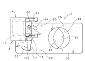
アイリス装置1は、図2に示すように、長方形に形成した一枚のベースプレート31を有し、このベースプレート31の長手方向中央位置からやや一側へオフセットした位置に、光路Rcを確保する円形の開口部32を形成する。そして、この開口部32に、図4に示すアイリス羽根部2を付設する。アイリス羽根部2は、薄い金属プレート材により形成し、かつベースプレート31に対して直進方向(長手方向)Fsにスライド変位自在に配する第一アイリス羽根2aと第二アイリス羽根2bを有する。この場合、各アイリス羽根2a及び2bは、形状は異なるも全体の重量は同程度に形成する。   As shown in FIG. 2, the iris device 1 has a single base plate 31 formed in a rectangular shape, and has a circular shape that secures an optical path Rc at a position slightly offset from the center position in the longitudinal direction of the base plate 31 to one side. Opening 32 is formed. Then, the iris blade portion 2 shown in FIG. The iris blade portion 2 includes a first iris blade 2a and a second iris blade 2b that are formed of a thin metal plate material and are slidably displaced in a straight direction (longitudinal direction) Fs with respect to the base plate 31. In this case, the iris blades 2a and 2b are formed in the same weight although the shapes are different.

第二アイリス羽根2bは、図4に示すように、長手方向(直進方向)Fsの一端側に、開口部32の径よりも若大きい曲率により半円状に湾曲形成したアイリス部33を設けるとともに、他端側に、後述する駆動部3に接続する接続孔部34を設ける。接続孔部34は、長手方向Fsに対して直角方向の一側(下側)に設け、長手方向Fsに対して直角方向に長いスリットにより形成する。また、第一アイリス羽根2aは、図4に示すように、長手方向Fsの一端側に、アイリス部33に対向する逆形状のアイリス部35を設けるとともに、他端側に、後述する変位伝達機構5に接続する接続孔部36を設ける。アイリス部35は、開口部32の径よりも若大きい曲率により半円状に湾曲形成する。接続孔部36は、長手方向Fsに対して直角方向の他側(上側)に設け、長手方向Fsに対して直角方向に長いスリットにより形成する。   As shown in FIG. 4, the second iris blade 2 b is provided with an iris portion 33 that is curved in a semicircular shape with a curvature that is slightly larger than the diameter of the opening 32 on one end side in the longitudinal direction (straight direction) Fs. On the other end side, a connection hole portion 34 connected to the drive unit 3 described later is provided. The connection hole portion 34 is provided on one side (lower side) in a direction perpendicular to the longitudinal direction Fs, and is formed by a slit that is long in the direction perpendicular to the longitudinal direction Fs. Further, as shown in FIG. 4, the first iris blade 2 a is provided with a reverse-shaped iris portion 35 facing the iris portion 33 on one end side in the longitudinal direction Fs, and a displacement transmission mechanism to be described later on the other end side. 5 is provided. The iris part 35 is curved and formed in a semicircular shape with a curvature that is slightly larger than the diameter of the opening part 32. The connection hole 36 is provided on the other side (upper side) in the direction perpendicular to the longitudinal direction Fs, and is formed by a slit that is long in the direction perpendicular to the longitudinal direction Fs.

そして、各アイリス羽根2a及び2bをベースプレート31に取付ける際には、ガイド機構18を介して取付ける。ガイド機構18は、各アイリス羽根2a及び2bにそれぞれ三つずつ形成したスリット部19…と、各スリット部19…に係合させることにより各アイリス羽根2a及び2bを直進方向Fsにガイドするガイドピン部20…を備える。ガイドピン部20…は、図1に示すように、一端に一体形成した広幅円形のピン頭部37…を有し、ガイドピン部20…をベースプレート31に取付ける際には、ガイドピン部20…を、第一アイリス羽根2aと第二アイリス羽根2bの一方又は双方におけるスリット部19…を挿通させ、先端を、ベースプレート31に形成した取付孔部38…に圧入等により固定する。この場合、ガイドピン部20…を固定するベースプレート31の位置は四個所となる。   When the iris blades 2 a and 2 b are attached to the base plate 31, they are attached via the guide mechanism 18. The guide mechanism 18 includes three slit portions 19 formed on each of the iris blades 2a and 2b, and guide pins that guide the iris blades 2a and 2b in the straight direction Fs by engaging with the slit portions 19. The unit 20 is provided. As shown in FIG. 1, the guide pin portions 20 have wide circular pin heads 37 integrally formed at one end. When the guide pin portions 20 are attached to the base plate 31, the guide pin portions 20. Are inserted through the slits 19 in one or both of the first iris blade 2a and the second iris blade 2b, and the tips are fixed to the mounting holes 38 formed in the base plate 31 by press-fitting or the like. In this case, there are four positions of the base plate 31 for fixing the guide pin portions 20.

また、ガイドピン部20…を取付ける際には、ガイドピン部20…の外周面に、当該ガイドピン部20…に対して回動自在となるカラー部材21…を装填する。カラー部材21は、金属素材により円筒状に形成し、軸方向長さは、第一アイリス羽根2aの厚さと第二アイリス羽根2bの厚さを加えた寸法よりも若長くするとともに、外径(直径)は、スリット部19の幅より若小さく選定する。このようなカラー部材21…を装填することにより、特に、アイリス羽根2a…の開度制御を短い周期により繰り返し、かつ使用時の温度が高温(200〔℃〕程度)になるプロジェクタに用いた際のアイリス羽根部2における金属同士のカジリを防止でき、アイリス羽根部2の耐久性,円滑性及び安定性の向上に寄与できる。即ち、各アイリス羽根2a…やガイドピン部20…は、高温環境下で使用するため、耐熱性の高い金属素材が用いられるが、それ故に金属同士のカジリも発生しやすくなる。しかし、カラー部材21…を装填することにより、このカジリを有効に防止できる利点がある。   Further, when the guide pin portions 20 are attached, collar members 21 that are rotatable with respect to the guide pin portions 20 are loaded on the outer peripheral surfaces of the guide pin portions 20. The collar member 21 is formed of a metal material in a cylindrical shape, and its axial length is made slightly longer than the dimension obtained by adding the thickness of the first iris blade 2a and the thickness of the second iris blade 2b, and the outer diameter ( The diameter is selected to be smaller than the width of the slit portion 19. By loading such collar members 21..., The opening control of the iris blades 2 a... Is repeated with a short cycle, and the projector is used in a projector where the temperature during use is high (about 200 ° C.). It is possible to prevent galling between metals in the iris blade part 2 and to contribute to improvement in durability, smoothness and stability of the iris blade part 2. That is, since the iris blades 2a and the guide pin portions 20 are used in a high-temperature environment, a metal material having high heat resistance is used. However, galling between metals is likely to occur. However, there is an advantage that this galling can be effectively prevented by loading the collar members 21.

一方、ベースプレート31における長手方向Fsの端部であって、上述した接続孔部34の近傍には駆動部3を配設する。駆動部3には、リニアモータ4を使用し、このリニアモータ4における可動出力部4oの変位を第一アイリス羽根2aにそのまま伝達できるように構成する。図5に、使用するリニアモータ4を分解した原理説明用斜視図を示す。   On the other hand, the drive unit 3 is disposed at the end of the base plate 31 in the longitudinal direction Fs and in the vicinity of the connection hole 34 described above. A linear motor 4 is used for the drive unit 3, and the displacement of the movable output unit 4 o in the linear motor 4 can be transmitted to the first iris blade 2 a as it is. FIG. 5 is an exploded perspective view for explaining the principle of the linear motor 4 to be used.

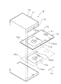
リニアモータ4は、コの字形に形成したヨーク13とこのヨーク13の上下に対峙する一対の内面の一方に固定したマグネット12を有する界磁部11を備えるとともに、界磁部11の内部に配してマグネット12に対向するコイル基板15を備える。この場合、マグネット12は、コイル基板15の変位方向(直進方向Fs)にそれぞれN極とS極が着磁されている。   The linear motor 4 includes a field portion 11 having a yoke 13 formed in a U-shape and a magnet 12 fixed to one of a pair of inner surfaces facing the top and bottom of the yoke 13, and is disposed inside the field portion 11. Then, a coil substrate 15 facing the magnet 12 is provided. In this case, the magnet 12 has a north pole and a south pole magnetized in the displacement direction (straight forward direction Fs) of the coil substrate 15.

また、コイル基板15は、上面15uにプリントパターンにより形成したコイル15pを有するとともに、下面15dにプリントパターンにより形成したコイル15qを有し、このコイル基板15の先端側が可動出力部4oとなる。したがって、コイル基板15の先端側には、第一アイリス羽根2a及び第二アイリス羽根2b側に接続する接続孔部41を有し、この接続孔部41は、長手方向Fsに対して直角方向に長いスリットにより形成する。15pa,15pc,15qc,15qbは、各コイル15p,15qの接続端部を示し、接続端部15pcと15qcはコイル基板15を貫通して接続されている。このコイル基板15は、図2に示すように、スライド支持機構42により支持される。スライド支持機構42は、ヨーク13から突出させた一対のアーム部43,44により保持された一対のガイドシャフト45,46を有し、このガイドシャフト45,46によりスライダ47,48がそれぞれスライド自在に支持されるとともに、各スライダ47,48にコイル基板15の両側端辺をそれぞれ固定する。これにより、コイル基板15は、直進方向Fsに変位自在となる。なお、図1に示すように、コイル基板15には、コイル基板15の位置を検出するためのホール素子49を備える。このようなタイプのリニアモータ4を使用することにより、可動出力部4oが軽量化されるため、高応答化,高速化及び高精度化の向上に寄与できる利点がある。   The coil substrate 15 has a coil 15p formed by a printed pattern on the upper surface 15u and a coil 15q formed by a printed pattern on the lower surface 15d, and the tip side of the coil substrate 15 becomes the movable output portion 4o. Therefore, the coil substrate 15 has a connection hole 41 connected to the first iris blade 2a and the second iris blade 2b side on the tip side, and the connection hole 41 is perpendicular to the longitudinal direction Fs. Formed by long slits. Reference numerals 15pa, 15pc, 15qc, and 15qb denote connection end portions of the coils 15p and 15q. The connection end portions 15pc and 15qc are connected through the coil substrate 15. As shown in FIG. 2, the coil substrate 15 is supported by a slide support mechanism 42. The slide support mechanism 42 has a pair of guide shafts 45 and 46 held by a pair of arm portions 43 and 44 protruding from the yoke 13, and the sliders 47 and 48 are slidable by the guide shafts 45 and 46, respectively. While being supported, both side edges of the coil substrate 15 are fixed to the sliders 47 and 48, respectively. Thereby, the coil board | substrate 15 becomes displaceable to the linear advance direction Fs. As shown in FIG. 1, the coil substrate 15 includes a hall element 49 for detecting the position of the coil substrate 15. By using this type of linear motor 4, the movable output portion 4 o is reduced in weight, so that there is an advantage that it is possible to contribute to improvement in response, speed, and accuracy.

さらに、ベースプレート31における長手方向Fsの端部であって、リニアモータ4の近傍には、変位伝達機構5を配設する。変位伝達機構5は、長手方向中央位置が支軸部16により回動自在に支持された回動リンク17を備え、この回動リンク17の一端17s側を可動出力部4oに接続するとともに、回動リンク17の他端17t側を第二アイリス羽根2bに接続する。この場合、図1に示すように、回動リンク17の一端17s側の上面に、係合ピン51を上方に突出させて固定するとともに、一端17s側の下面であって、係合ピン51と同軸になる係合ピン52を下方に突出させて固定し、さらに、回動リンク17の他端17t側の下面に、係合ピン53を下方に突出させて固定する。そして、係合ピン51をコイル基板15の接続孔部41に係合させるとともに、係合ピン52を第一アイリス羽根2aの接続孔部34に係合させ、さらに、係合ピン53を第二アイリス羽根2bの接続孔部36に係合させる。このため、ベースプレート31には、係合ピン52及び53が貫通し、かつ係合ピン52及び53の変位を許容する二つの弓形開孔部55…が形成してある。   Further, the displacement transmission mechanism 5 is disposed in the vicinity of the linear motor 4 at the end of the base plate 31 in the longitudinal direction Fs. The displacement transmission mechanism 5 includes a rotation link 17 whose center position in the longitudinal direction is rotatably supported by the support shaft portion 16. One end 17 s side of the rotation link 17 is connected to the movable output portion 4 o, and The other end 17t side of the moving link 17 is connected to the second iris blade 2b. In this case, as shown in FIG. 1, the engaging pin 51 protrudes upward and is fixed to the upper surface on the one end 17s side of the rotation link 17, and the lower surface on the one end 17s side The coaxial engaging pin 52 protrudes downward and is fixed, and further, the engaging pin 53 protrudes downward and is fixed to the lower surface of the rotating link 17 on the other end 17t side. Then, the engagement pin 51 is engaged with the connection hole 41 of the coil substrate 15, the engagement pin 52 is engaged with the connection hole 34 of the first iris blade 2a, and the engagement pin 53 is Engage with the connection hole 36 of the iris blade 2b. For this reason, the base plate 31 is formed with two arcuate openings 55 through which the engaging pins 52 and 53 pass and the displacement of the engaging pins 52 and 53 is allowed.

次に、本実施形態に係るアイリス装置1の動作について、図1〜図6を参照して説明する。   Next, operation | movement of the iris apparatus 1 which concerns on this embodiment is demonstrated with reference to FIGS.

まず、駆動部3を構成するリニアモータ4は、図5に示す接続端部15paと15qb間に正方向の駆動電流を流すことにより、コイル基板15がヨーク13から突出する方向に変位する。また、接続端部15paと15qb間に逆方向の駆動電流を流すことにより、コイル基板15がヨーク13に進入する方向に変位する。コイル基板15の位置は、ホール素子49により検出されるため、コイル基板15の位置に基づき駆動電流をフィードバック制御することにより、コイル基板15の位置制御を行うことができる。   First, the linear motor 4 constituting the drive unit 3 is displaced in a direction in which the coil substrate 15 protrudes from the yoke 13 by causing a positive drive current to flow between the connection ends 15pa and 15qb shown in FIG. Further, when a driving current in the opposite direction is passed between the connection end portions 15pa and 15qb, the coil substrate 15 is displaced in the direction of entering the yoke 13. Since the position of the coil substrate 15 is detected by the Hall element 49, the position of the coil substrate 15 can be controlled by feedback controlling the drive current based on the position of the coil substrate 15.

一方、リニアモータ4のコイル基板15は可動出力部4oとなるため、この可動出力部4oの変位は、係合ピン51及び52を介して第一アイリス羽根2aに伝達され、この際、可動出力部4oの変位量は、第一アイリス羽根2aにそのまま伝達される。また、可動出力部4oの変位は、変位伝達機構5を介して第二アイリス羽根2bに伝達される。この場合、可動出力部4oの前進(後退)により、第一アイリス羽根2aが前進(後退)し、第一アイリス羽根2aにおけるアイリス部33は開口部32を閉じる(開く)方向、即ち、開放絞り(小絞り)側から小絞り(開放絞り)側へ変位するとともに、可動出力部4oの前進(後退)により、第二アイリス羽根2bが後退(前進)し、第二アイリス羽根2bにおけるアイリス部35は開口部32を閉じる(開く)方向、即ち、開放絞り(小絞り)側から小絞り(開放)側へ変位する。これにより、第一アイリス羽根2aと第二アイリス羽根2bは対称方向に変位する。   On the other hand, since the coil substrate 15 of the linear motor 4 becomes the movable output portion 4o, the displacement of the movable output portion 4o is transmitted to the first iris blade 2a via the engagement pins 51 and 52. The displacement amount of the portion 4o is transmitted as it is to the first iris blade 2a. Further, the displacement of the movable output portion 4o is transmitted to the second iris blade 2b via the displacement transmission mechanism 5. In this case, the first iris blade 2a moves forward (retreats) by the advance (retreat) of the movable output portion 4o, and the iris portion 33 of the first iris blade 2a closes (opens) the opening 32, that is, an open aperture. While being displaced from the (small aperture) side to the small aperture (open aperture) side, the second iris blade 2b is retracted (advanced) by the advance (retreat) of the movable output portion 4o, and the iris portion 35 in the second iris blade 2b. Is displaced in the direction of closing (opening) the opening 32, that is, from the open stop (small stop) side to the small stop (open) side. Thereby, the 1st iris blade 2a and the 2nd iris blade 2b are displaced in a symmetrical direction.

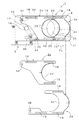
本実施形態に係るアイリス装置1は、図6に示すように、プロジェクタMにおける光学系Cの光路Rcに配設し、通過する光量を可変することができる。具体的には、レンズユニットL内における所定位置にアイリス装置1を内蔵させる。なお、例示のプロジェクタMは、LCDパネル3枚(モノクロパネル)を使用した3板式プロジェクタである。このプロジェクタMは、ダイクロイックミラーによってRGB(R:赤,G:緑,B:青)各色に分離し、各LCDパネルを通過させて1つの映像に合成する。図6中、61はGBを反射してRを透過する第一ミラー、62はBを反射してGを透過する第二ミラー、63及び64は全反射する第三及び第四ミラー、65はBを反射してRを透過する第五ミラー、66はRBを反射してGを透過する第六ミラーをそれぞれ示すとともに、67はR用LCDパネル、68はG用LCDパネル、69はB用LCDパネルをそれぞれ示す。また、70は光源ランプである。   As shown in FIG. 6, the iris device 1 according to the present embodiment is arranged in the optical path Rc of the optical system C in the projector M, and can vary the amount of light passing therethrough. Specifically, the iris device 1 is built in a predetermined position in the lens unit L. The example projector M is a three-plate projector using three LCD panels (monochrome panel). This projector M is separated into RGB (R: red, G: green, B: blue) colors by a dichroic mirror, and passes through each LCD panel to compose one image. In FIG. 6, 61 is a first mirror that reflects GB and transmits R, 62 is a second mirror that reflects B and transmits G, 63 and 64 are third and fourth mirrors that totally reflect, 65 is A fifth mirror that reflects B and transmits R, 66 indicates a sixth mirror that reflects RB and transmits G, 67 is an LCD panel for R, 68 is an LCD panel for G, and 69 is for B Each LCD panel is shown. Reference numeral 70 denotes a light source lamp.

ところで、この光源ランプ70は発熱源となり、通常、プロジェクタMの内部は、200〔℃〕程度の高温になるが、前述したように、第一アイリス羽根2a及び第二アイリス羽根2bを直進方向Fsにガイドするガイド機構18におけるガイドピン部20…の外周面に、当該ガイドピン部20…に対して回動自在となるカラー部材21…を装填するため、特に、アイリス羽根2a…の開度制御を短い周期により繰り返して行うプロジェクタMに用いた場合であっても、アイリス羽根部2における金属同士のカジリを有効に防止でき、アイリス羽根部2の耐久性,円滑性及び安定性の向上に寄与できる。   By the way, the light source lamp 70 serves as a heat source, and normally the interior of the projector M becomes a high temperature of about 200 [° C.], but as described above, the first iris blade 2a and the second iris blade 2b are moved in the straight direction Fs. In order to load collar members 21 that can rotate with respect to the guide pin portions 20 on the outer peripheral surface of the guide pin portions 20 of the guide mechanism 18 that guides the guide mechanism 18 in particular, the opening control of the iris blades 2a. Can be effectively prevented from being galvanized between metals in the iris blade part 2 even if it is used in a projector M that is repeatedly performed in a short cycle, and contributes to improving the durability, smoothness and stability of the iris blade part 2 it can.

よって、このような本実施形態に係るアイリス装置1によれば、リニアモータ4の可動出力部4oにおける直進方向Fsの変位量を第一アイリス羽根2aにそのまま伝達するとともに、可動出力部4oにおける直進方向Fsの変位量を、直進方向Fsに変位自在に配した第一アイリス羽根2a及び第二アイリス羽根2bに伝達するため、伝達経路の単純化及びイナーシャの低減を図ることができ、アイリス羽根2a…の開度制御を短い周期により繰り返して行う際に要請される高応答化,高速化及び制御の高精度化を実現することができる。   Therefore, according to the iris device 1 according to the present embodiment as described above, the displacement amount in the straight traveling direction Fs in the movable output portion 4o of the linear motor 4 is transmitted to the first iris blade 2a as it is, and the straight travel in the movable output portion 4o. Since the displacement amount in the direction Fs is transmitted to the first iris blade 2a and the second iris blade 2b that are displaceably arranged in the straight traveling direction Fs, the transmission path can be simplified and the inertia can be reduced. It is possible to achieve high response, high speed, and high control accuracy required when the opening degree control of... Is repeatedly performed with a short cycle.

以上、最良の実施形態について詳細に説明したが、本発明は、このような実施形態に限定されるものではなく、細部の構成,形状,素材,数量等において、本発明の要旨を逸脱しない範囲で、任意に変更,追加,削除することができる。   Although the best embodiment has been described in detail above, the present invention is not limited to such an embodiment, and the scope of the present invention is not deviated from the gist of the present invention in the detailed configuration, shape, material, quantity, and the like. It can be changed, added, or deleted arbitrarily.

例えば、可動出力部4oの変位量を第一アイリス羽根2aにそのまま伝達する構成として、係合ピン51,52を介在させる形態を例示したが、勿論、可動出力部4oを第一アイリス羽根2aに直結してもよい。また、リニアモータ4のタイプは、必ずしも例示のタイプに限定されるものではなく、他のタイプによるリニアモータであってもよい。なお、アイリス装置1の用途として、プロジェクタ(フロントプロジェクタ)Mを例示したが、リアプロジェクションテレビなど、同様の光学系を備える各種機器に適用できる。   For example, as an arrangement in which the displacement amount of the movable output portion 4o is transmitted to the first iris blade 2a as it is, the configuration in which the engagement pins 51 and 52 are interposed is illustrated. Of course, the movable output portion 4o is connected to the first iris blade 2a. It may be directly connected. The type of the linear motor 4 is not necessarily limited to the illustrated type, and may be a linear motor of another type. In addition, although the projector (front projector) M was illustrated as an application of the iris device 1, it can be applied to various devices including a similar optical system such as a rear projection television.

本発明の最良の実施形態に係るアイリス装置の一部断面平面図、A partial cross-sectional plan view of an iris device according to the best embodiment of the present invention, 同アイリス装置の開放絞り状態を示す正面図、Front view showing the open iris state of the iris device, 同アイリス装置の小絞り状態を示す正面図、Front view showing a small aperture state of the iris device, 同アイリス装置のアイリス羽根部の分解抽出図を含む開放絞り状態を示す背面図、A rear view showing an open aperture state including an exploded extraction view of the iris blade portion of the iris device; 同アイリス装置に使用するリニアモータを分解した原理説明用斜視図、An exploded perspective view of the principle of the linear motor used in the iris device, 同アイリス装置を適用したプロジェクタの概要図、Schematic diagram of a projector to which the iris device is applied,

符号の説明Explanation of symbols

1:アイリス装置,2:アイリス羽根部,2a:第一アイリス羽根,2b:第二アイリス羽根,3:駆動部,4:リニアモータ,4o:可動出力部,5:変位伝達機構,11:界磁部,12:マグネット,13:ヨーク,15p:コイル,15q:コイル,15:コイル基板,16:支軸部,17:回動リンク,18:ガイド機構,19…:スリット部,20…:ガイドピン部,21:カラー部材,C:光学系,Rc:光路,Fs:直進方向   DESCRIPTION OF SYMBOLS 1: Iris apparatus, 2: Iris blade part, 2a: 1st iris blade, 2b: 2nd iris blade, 3: Drive part, 4: Linear motor, 4o: Movable output part, 5: Displacement transmission mechanism, 11: Field Magnetic part, 12: magnet, 13: yoke, 15p: coil, 15q: coil, 15: coil substrate, 16: support shaft part, 17: rotating link, 18: guide mechanism, 19 ...: slit part, 20 ...: Guide pin part, 21: collar member, C: optical system, Rc: optical path, Fs: straight direction

Claims (5)

光学系の光路に配設することにより通過する光量を可変するアイリス装置において、直進方向に変位自在に配した第一アイリス羽根及び第二アイリス羽根を有するアイリス羽根部と、可動出力部の変位量を前記第一アイリス羽根にそのまま伝達するリニアモータを有する駆動部と、前記可動出力部の変位量を前記第二アイリス羽根に伝達し、かつ前記第二アイリス羽根を前記第一アイリス羽根に対して対称方向に変位させる変位伝達機構を備えることを特徴とするアイリス装置。   In an iris device that varies the amount of light passing by being disposed in the optical path of the optical system, an iris blade portion having a first iris blade and a second iris blade arranged so as to be displaceable in a straight advance direction, and a displacement amount of the movable output portion A drive unit having a linear motor that directly transmits the first iris blade to the first iris blade, a displacement amount of the movable output unit is transmitted to the second iris blade, and the second iris blade is transmitted to the first iris blade. An iris device comprising a displacement transmission mechanism for displacing in a symmetric direction. 前記リニアモータは、マグネット及びヨークを有する界磁部と、コイルを形成したコイル基板を用いた可動出力部を備えることを特徴とする請求項1記載のアイリス装置。   2. The iris device according to claim 1, wherein the linear motor includes a field part having a magnet and a yoke, and a movable output part using a coil substrate on which a coil is formed. 前記変位伝達機構は、長手方向中央位置が支軸部により回動自在に支持された回動リンクを備え、この回動リンクの一端側を前記可動出力部に接続するとともに、前記回動リンクの他端側を前記第二アイリス羽根に接続することを特徴とする請求項1記載のアイリス装置。   The displacement transmission mechanism includes a rotation link whose center in the longitudinal direction is rotatably supported by a support shaft, and connects one end side of the rotation link to the movable output unit. 2. The iris device according to claim 1, wherein the other end side is connected to the second iris blade. 前記第一アイリス羽根及び前記第二アイリス羽根に形成した一又は二以上のスリット部と、このスリット部に係合させることにより前記第一アイリス羽根及び前記第二アイリス羽根を直進方向にガイドするガイドピン部を有するガイド機構を備えることを特徴とする請求項1記載のアイリス装置。   One or more slit portions formed in the first iris blade and the second iris blade, and a guide for guiding the first iris blade and the second iris blade in the straight direction by engaging with the slit portion. The iris device according to claim 1, further comprising a guide mechanism having a pin portion. 前記ガイドピン部の外周面には、当該ガイドピン部に対して回動自在となるカラー部材を装填することを特徴とする請求項4記載のアイリス装置。   The iris device according to claim 4, wherein a collar member that is rotatable with respect to the guide pin portion is loaded on an outer peripheral surface of the guide pin portion.
JP2006012612A 2006-01-20 2006-01-20 Iris device Pending JP2007193202A (en)

Priority Applications (1)

Application Number Priority Date Filing Date Title
JP2006012612A JP2007193202A (en) 2006-01-20 2006-01-20 Iris device

Applications Claiming Priority (1)

Application Number Priority Date Filing Date Title
JP2006012612A JP2007193202A (en) 2006-01-20 2006-01-20 Iris device

Publications (1)

Publication Number Publication Date
JP2007193202A true JP2007193202A (en) 2007-08-02

Family

ID=38448930

Family Applications (1)

Application Number Title Priority Date Filing Date
JP2006012612A Pending JP2007193202A (en) 2006-01-20 2006-01-20 Iris device

Country Status (1)

Country Link
JP (1) JP2007193202A (en)

Cited By (3)

* Cited by examiner, † Cited by third party
Publication number Priority date Publication date Assignee Title
JP2017201382A (en) * 2016-05-04 2017-11-09 エルジー エレクトロニクス インコーポレイティド Mobile terminal equipped with camera module
CN110865498A (en) * 2018-08-28 2020-03-06 三星电机株式会社 Aperture module, camera module and portable electronic device
US10969654B2 (en) * 2019-06-18 2021-04-06 Samsung Electro-Mechanics Co., Ltd. Aperture module and camera module including the same

Citations (3)

* Cited by examiner, † Cited by third party
Publication number Priority date Publication date Assignee Title
JPH0588233A (en) * 1991-09-25 1993-04-09 Canon Inc Stopping blade driving device
JPH08136791A (en) * 1994-11-04 1996-05-31 Nikon Corp Zoom lens barrel
JP2001125165A (en) * 1999-10-27 2001-05-11 Nidec Copal Corp Shutter for camera

Patent Citations (3)

* Cited by examiner, † Cited by third party
Publication number Priority date Publication date Assignee Title
JPH0588233A (en) * 1991-09-25 1993-04-09 Canon Inc Stopping blade driving device
JPH08136791A (en) * 1994-11-04 1996-05-31 Nikon Corp Zoom lens barrel
JP2001125165A (en) * 1999-10-27 2001-05-11 Nidec Copal Corp Shutter for camera

Cited By (3)

* Cited by examiner, † Cited by third party
Publication number Priority date Publication date Assignee Title
JP2017201382A (en) * 2016-05-04 2017-11-09 エルジー エレクトロニクス インコーポレイティド Mobile terminal equipped with camera module
CN110865498A (en) * 2018-08-28 2020-03-06 三星电机株式会社 Aperture module, camera module and portable electronic device
US10969654B2 (en) * 2019-06-18 2021-04-06 Samsung Electro-Mechanics Co., Ltd. Aperture module and camera module including the same

Similar Documents

Publication Publication Date Title
US7316514B2 (en) Light controller and image pickup device including the same
JP4189412B2 (en) Electromagnetic drive device and light amount adjustment device using the same
KR20050078992A (en) Image pickup device and driving motor thereof
JP2007193202A (en) Iris device
US8511836B2 (en) Diaphragm apparatus for projectors
US9798158B2 (en) Optical apparatus capable of retracting optical element from optical path
KR20110096391A (en) Camera shutter device
JP5999186B2 (en) Lens barrel
US9134588B2 (en) Stop apparatus, and lens apparatus and image pickup apparatus having the same
CN104081273A (en) Focal plane shutter, imaging device and digital camera
JP2005309318A (en) Diaphragm mechanism and camera using same
JP4595452B2 (en) Exposure control mechanism and lens barrel
JP5117315B2 (en) Projector aperture device
JP2010054610A (en) Diaphragm device for projector
JP6595830B2 (en) Blade driving device and optical apparatus provided with blade driving device
CN219065956U (en) Blade driving device and imaging device provided with same
JP4470106B2 (en) Imaging device and drive motor
JP2008051989A (en) Shutter device, lens barrel, and camera
JP2016071310A (en) Filter changing device
JP5373261B2 (en) Focal plane shutter for digital camera
JP2015099332A (en) Quantity-of-light adjustment device and imaging device
JPS60243612A (en) Optical device
JP2010032695A (en) Lens drive device and optical equipment
JPH11202400A (en) Photographing magnification display device for lens barrel capable of switching automatic focusing and manual focusing
JP2019101154A (en) Blade driving device

Legal Events

Date Code Title Description
A621 Written request for application examination

Free format text: JAPANESE INTERMEDIATE CODE: A621

Effective date: 20090115

A977 Report on retrieval

Free format text: JAPANESE INTERMEDIATE CODE: A971007

Effective date: 20111014

A131 Notification of reasons for refusal

Free format text: JAPANESE INTERMEDIATE CODE: A131

Effective date: 20111026

A02 Decision of refusal

Free format text: JAPANESE INTERMEDIATE CODE: A02

Effective date: 20120229