JP2007193165A - Image forming apparatus - Google Patents
Image forming apparatus Download PDFInfo
- Publication number
- JP2007193165A JP2007193165A JP2006012111A JP2006012111A JP2007193165A JP 2007193165 A JP2007193165 A JP 2007193165A JP 2006012111 A JP2006012111 A JP 2006012111A JP 2006012111 A JP2006012111 A JP 2006012111A JP 2007193165 A JP2007193165 A JP 2007193165A
- Authority
- JP
- Japan
- Prior art keywords
- image
- forming apparatus
- image forming
- sheet
- fixing
- Prior art date
- Legal status (The legal status is an assumption and is not a legal conclusion. Google has not performed a legal analysis and makes no representation as to the accuracy of the status listed.)
- Withdrawn
Links
Images


Abstract
Description
この発明は、電子写真方式等を採用した複写機やプリンター、ファクシミリ、あるいはこれらの機能を兼ね備えた複合機等の画像形成装置に関し、特に、定着手段によって小サイズの用紙にトナー像を連続して定着した後に、大サイズの用紙にトナー像を定着する場合のように、非通紙領域で熱が消費されず蓄熱されることに伴う技術的課題を、長い非通紙の空白時間を要することなく解決可能とした画像形成装置に関するものである。
BACKGROUND OF THE
従来、この種の電子写真方式を採用した複写機やプリンター等の画像形成装置においては、感光体ドラム上に画像情報に応じてトナー像を形成し、当該感光体ドラム上に形成されたトナー像を、用紙上に直接転写するか、あるいは、同一又は複数の感光体ドラム上に順次形成されるイエロー、マゼンタ、シアン、黒等の互いに色の異なる複数のトナー像を、一旦、中間転写体上に重ね合わせた状態で転写した後、当該中間転写体から用紙上に一括して転写した後、定着装置によって用紙にトナー像を定着することにより、モノクロやフルカラーの画像を形成するように構成されている。 Conventionally, in an image forming apparatus such as a copying machine or a printer that employs this type of electrophotographic method, a toner image is formed on a photosensitive drum according to image information, and the toner image formed on the photosensitive drum Or a plurality of toner images of different colors such as yellow, magenta, cyan and black, which are sequentially formed on the same or a plurality of photosensitive drums, are temporarily transferred onto the intermediate transfer member. After being transferred in a superposed state, the image is transferred from the intermediate transfer body onto the paper at once, and then the toner image is fixed on the paper by a fixing device, thereby forming a monochrome or full-color image. ing.
ところで、かかる画像形成装置では、定着装置によって用紙上にトナー像を定着する際に、小サイズの用紙を連続して通紙することにより定着処理を行うと、定着装置の加熱ロール等の加熱部材は、最大サイズの用紙を定着可能なように加熱されるため、最大サイズの用紙と小サイズの用紙とのサイズ差に対応する非通紙領域では、定着ニップ部において熱が消費されずに蓄熱されることになる。 By the way, in such an image forming apparatus, when fixing the toner image onto the paper by the fixing device, when fixing processing is performed by continuously passing a small size paper, a heating member such as a heating roll of the fixing device. Is heated so that the maximum size paper can be fixed, and in the non-sheet passing area corresponding to the size difference between the maximum size paper and the small size paper, heat is not consumed in the fixing nip portion, and heat is stored. Will be.
その結果、上記画像形成装置では、定着装置の加熱ロールの非通紙領域の温度が、所定の定着温度よりも高い温度に昇温してしまい、加熱ロールの非通紙領域の部分が過大に熱膨張し、用紙に皺が発生したり、通紙領域との間に定着性に差が生じるという問題点を有していた。 As a result, in the image forming apparatus, the temperature of the non-sheet passing area of the heating roll of the fixing device is raised to a temperature higher than a predetermined fixing temperature, and the portion of the non-sheet passing area of the heating roll is excessively large. There is a problem that the sheet expands due to heat and wrinkles are generated on the sheet or a difference in fixing property occurs between the sheet passing area.
そこで、かかる定着装置の非通紙部の昇温に伴う問題点を解決し得る技術としては、特開平04−322284号公報等に開示されているものが既に提案されている。 In view of this, a technique disclosed in Japanese Patent Laid-Open No. 04-322284 has already been proposed as a technique that can solve the problems associated with the temperature rise of the non-sheet passing portion of the fixing device.
この特開平04−322284号公報に係る画像形成装置は、定着ローラと該定着ローラに圧接される加圧ローラとを備え、少なくとも定着ローラを加熱することにより未定着トナー像を転写紙に加熱定着する定着装置と、該定着装置に設けられ、定着ローラの軸線方向にて異なる複数の領域の温度を検知する温度検知手段と、前記転写紙が排出されたことを検知する手段とを有し、複数の異なる紙サイズの記録画像が得られる画像形成装置において、紙サイズが最大サイズ以外の記録画像を複数枚形成し、その最後の転写紙が前記排出検知手段によって検知された信号により、前記定着ローラの所定時間空回転するように構成したものである。 An image forming apparatus according to Japanese Patent Application Laid-Open No. 04-322284 includes a fixing roller and a pressure roller pressed against the fixing roller, and heats and fixes the unfixed toner image on the transfer paper by heating at least the fixing roller. A fixing device that detects the temperature of a plurality of regions that are provided in the fixing device and differ in the axial direction of the fixing roller, and a means that detects that the transfer paper has been discharged. In an image forming apparatus capable of obtaining a plurality of recording images of different paper sizes, a plurality of recording images having a paper size other than the maximum size are formed, and the last transfer paper is detected by the signal detected by the discharge detection unit. The roller is configured to idle for a predetermined time.
しかし、上記特開平04−322284号公報に係る画像形成装置の場合には、最後の転写紙が排出検知手段によって検知された信号により、定着ローラの所定時間空回転するように構成したものであり、前ジョブと次ジョブの合間に、定着ローラの温度分布が十分に均一化するまで、定着ローラを所定時間だけ空回転させた場合には、当該空回転の時間だけ長い空白時間を必要とし、画像形成装置の実質的な動作が短くなり、近年の高い生産性が要求される画像形成装置には適用できないという問題点を有していた。 However, in the case of the image forming apparatus according to Japanese Patent Laid-Open No. 04-322284, the last transfer sheet is configured to idle for a predetermined time by a signal detected by the discharge detection means. When the fixing roller is idled for a predetermined time until the temperature distribution of the fixing roller is sufficiently uniform between the previous job and the next job, a long blank time is required for the idle rotation time. The substantial operation of the image forming apparatus is shortened, and there is a problem that the image forming apparatus cannot be applied to an image forming apparatus that requires high productivity in recent years.
そこで、上記の問題点を解決し得る技術としては、特開平11−73055号公報、特開2002−72763号公報、及び特開平11−52788号公報等に開示されたものが既に提案されている。 Therefore, as techniques that can solve the above-mentioned problems, those disclosed in JP-A-11-73055, JP-A-2002-72763, JP-A-11-52788, and the like have already been proposed. .
上記特開平11−73055号公報に係る画像形成装置の制御方法は、未定着像を担持したシート状の転写材への熱伝導のための外周面を有する回転体状の回転自在な定着体と、上記転写材を介して定着体に圧接される回転体状の回転自在な加圧体と、少なくとも定着体を加熱する加熱手段と、加圧体を回転駆動せしめる駆動機構とが設けられている加熱定着装置を備える画像形成装置の制御方法であって、複数枚の転写材への連続した定着処理後に、第一の規定時間に亘り駆動機構が加圧体を一方向に複数回転せしめることとする加熱定着装置を備える画像形成装置の制御方法において、B5サイズの転写材よりもサイズの小さい転写材たる小サイズ紙への複数枚に亘る連続定着処理後には、第一の規定時間よりも長い第二の規定時間に亘り駆動機構が加圧体を一方向に複数回転せしめるように構成されている。 A method for controlling an image forming apparatus according to the above Japanese Patent Application Laid-Open No. 11-73055 includes a rotatable fixing member having a rotating body having an outer peripheral surface for heat conduction to a sheet-like transfer material carrying an unfixed image. A rotary pressure member that is pressed against the fixing member through the transfer material, a heating unit that heats at least the fixing member, and a drive mechanism that rotates the pressure member. A method for controlling an image forming apparatus including a heat fixing device, wherein a driving mechanism rotates a pressure body a plurality of times in one direction for a first specified time after continuous fixing processing to a plurality of transfer materials. In the control method of the image forming apparatus provided with the heating and fixing device, after a continuous fixing process over a plurality of sheets to a small size paper which is a transfer material having a smaller size than the transfer material of B5 size, it is longer than the first specified time. Over the second specified time Drive mechanism is configured to allowed to multiple rotating pressing body in one direction.
また、上記特開2002−72763号公報に係る画像形成装置は、(A01)互いに圧接しながら回転し且つ圧接領域により形成される定着領域を通過する記録シート上の未定着トナー像を定着する加熱定着用回転部材および加圧定着用回転部材、(A02)前記加熱定着用回転部材の内部に配置され且つ前記記録シートの幅方向に延びて配置された大サイズシート定着時に使用する大サイズ時使用ヒータおよび前記大サイズシートに比較して小サイズのシート定着時に使用する小サイズ時使用ヒータと、前記加熱定着用回転部材とを有する加熱定着部材、(A03)前回ジョブで使用したシートサイズおよび画像記録枚数を記憶する前回ジョブ情報記憶手段、(A04)前回ジョブ終了時から次回ジョブ指令信号の入力時までの経過時間を計測する経過時間検出手段、(A05)次回ジョブで使用するシートサイズを検出し記憶する次回ジョブのシートサイズ記憶手段、(A06)前回ジョブで使用したシートが小サイズシートで次回ジョブで使用するシートが大サイズシートの場合に、前記経過時間に応じて前記小サイズ時使用ヒータのみをオンにして、前記加熱定着用回転部材および加圧定着用回転部材の空回転を実行する空回転実行手段を備えるように構成したものである。 Also, the image forming apparatus according to the above-mentioned Japanese Patent Application Laid-Open No. 2002-72763 (A01) is a heating that fixes an unfixed toner image on a recording sheet that rotates while being pressed against each other and passes through a fixing area formed by the pressing area. Rotating member for fixing and rotating member for pressure fixing, (A02) Large-sized sheet used for fixing a large-sized sheet disposed inside the rotating member for heating and fixing and extending in the width direction of the recording sheet A heating fixing member having a heater and a small size use heater used for fixing a small size sheet as compared to the large size sheet, and the heating fixing rotating member; (A03) sheet size and image used in the previous job; Previous job information storage means for storing the number of recordings, (A04) Measure the elapsed time from the end of the previous job to the input of the next job command signal Overtime detection means, (A05) Sheet size storage means for detecting and storing the sheet size used in the next job, (A06) The sheet used in the previous job is a small size sheet and the sheet used in the next job is large In the case of a size sheet, there is provided idle rotation execution means for performing only idle rotation of the heating and fixing rotation member and the pressure fixing rotation member by turning on only the small size use heater according to the elapsed time. It is configured.
さらに、上記特開平11−52788号公報に係る画像形成装置は、画像を熱で定着させる定着ローラを有し、電源投入後、コピー動作を開始する前に定着ローラを回転させる準備動作を行う画像形成装置において、ユーザによるコピー開始の指示があったとき、その指示により指定されたコピー条件に応じて、前記準備動作における前記定着ローラの回転時間を決定する回転時間決定手段と、該回転時間決定手段により決定された時間の経過の確認後に直ちに前記準備動作を停止して、コピー動作を開始する制御手段と、を備えるように構成したものである。 Further, the image forming apparatus according to the above-mentioned Japanese Patent Application Laid-Open No. 11-52788 has a fixing roller for fixing an image with heat, and performs an operation for performing a preparatory operation for rotating the fixing roller after the power is turned on and before starting a copying operation. In the forming apparatus, when there is an instruction to start copying by the user, a rotation time determining means for determining a rotation time of the fixing roller in the preparation operation according to a copy condition designated by the instruction, and the rotation time determination And a control means for stopping the preparation operation immediately after confirming the passage of the time determined by the means and starting the copy operation.
しかしながら、上記従来技術の場合には、次のような問題点を有している。すなわち、上記特開平11−73055号公報に係る画像形成装置の制御方法の場合は、B5サイズの転写材よりもサイズの小さい転写材たる小サイズ紙への複数枚に亘る連続定着処理後に、第一の規定時間よりも長い第二の規定時間に亘り駆動機構が加圧体を一方向に複数回転せしめるように構成したものであるため、非通紙領域の温度が昇温することに起因する問題を解決するには、第二の規定時間をある程度長く設定せざるを得ず、単に、定着ローラを所定時間だけ空回転する特開平04−322284号公報に比べれば、空回転時間を短縮することはできても、空回転時間を適切に設定することができないという問題点を有していた。 However, the conventional technique has the following problems. That is, in the case of the control method of the image forming apparatus according to the above Japanese Patent Application Laid-Open No. 11-73055, after the continuous fixing process over a plurality of sheets on a small size paper which is a transfer material smaller in size than the B5 size transfer material, This is because the drive mechanism is configured to rotate the pressurizing body a plurality of times in one direction over a second specified time longer than the one specified time, resulting in a temperature rise in the non-sheet passing region. In order to solve the problem, the second specified time has to be set to a certain length, and the idling time is shortened as compared with Japanese Patent Laid-Open No. 04-322284 in which the fixing roller is idly rotated for a predetermined time. Even though it was possible, the idle rotation time could not be set appropriately.
また、上記特開2002−72763号公報に係る画像形成装置の場合には、前回ジョブで使用したシートが小サイズシートで次回ジョブで使用するシートが大サイズシートの場合に、経過時間に応じて前記小サイズ時使用ヒータのみをオンにして、前記加熱定着用回転部材および加圧定着用回転部材の空回転を実行する空回転実行手段を備えるように構成したものであるが、小サイズ時使用ヒータが別途必要となり、コストアップを招くとともに、空回転を実行しても、環境温度の相違等によって、加熱定着用回転部材の温度が十分低下するか否か不明であり、やはり、空回転時間を適切に設定することができないという問題点を有していた。 Further, in the case of the image forming apparatus according to Japanese Patent Application Laid-Open No. 2002-72763, when the sheet used in the previous job is a small size sheet and the sheet used in the next job is a large size sheet, according to the elapsed time. It is configured to include idle rotation execution means for performing only idle rotation of the heating fixing rotating member and the pressure fixing rotating member by turning on only the heater used at the small size, but used at the small size. A separate heater is required, resulting in an increase in cost, and even if idling is performed, it is unclear whether the temperature of the rotating member for heating and fixing sufficiently decreases due to a difference in environmental temperature or the like. Has a problem that cannot be set appropriately.
さらに、上記特開平11−52788号公報に係る画像形成装置の場合には、画像を熱で定着させる定着ローラを有し、電源投入後、コピー動作を開始する前に定着ローラを回転させる準備動作を行う画像形成装置に関するものであり、前の定着処理に伴う定着ローラの非通紙領域の温度が不均一となることに起因する問題点に対しては効果が得られないという問題点を有していた。 Further, in the case of the image forming apparatus according to the above-mentioned Japanese Patent Application Laid-Open No. 11-52788, the image forming apparatus has a fixing roller for fixing the image with heat, and after the power is turned on, the preparatory operation for rotating the fixing roller before starting the copying operation This is related to an image forming apparatus that performs the above-described image processing, and has a problem that the effect cannot be obtained for a problem caused by non-uniform temperature of the non-sheet passing area of the fixing roller due to the previous fixing process. Was.
そこで、この発明は、上記従来技術の問題点を解決するためになされたものであり、その目的とするところは、定着手段によって小サイズの用紙にトナー像を連続して定着した後に、大サイズの用紙にトナー像を定着する場合のように、非通紙領域で熱が消費されず蓄熱されることに伴う紙しわの発生や、定着性の不均一等が発生することを、適切な空回転時間を設定することによって防止でき、画像形成動作を開始するまでの無駄な待ち時間を短縮することが可能な画像形成装置を提供することにある。 Accordingly, the present invention has been made to solve the above-described problems of the prior art, and an object of the present invention is to fix a large image after a toner image is continuously fixed on a small size paper by a fixing unit. As in the case where the toner image is fixed on the other paper, the generation of paper wrinkles due to the heat being stored in the non-sheet passing area without being consumed, the occurrence of non-uniform fixing properties, etc. An object of the present invention is to provide an image forming apparatus that can be prevented by setting a rotation time and can reduce a useless waiting time until an image forming operation is started.
すなわち、請求項1に記載された発明は、未定着トナー像が転写された用紙を、少なくとも一方が加熱源を有する一対の回転部材によって挟持しつつ搬送することにより、未定着トナー像を用紙上に定着する定着手段を備えた画像形成装置において、
前記定着手段によって最大サイズよりも小さいサイズの用紙を連続して定着した後、当該連続して定着したサイズの用紙よりもサイズの大きな用紙に未定着トナー像を定着する際に、前記回転部材の空回転を実行する空回転実行手段と、
前記空回転実行手段が実行する空回転時間を、次に定着処理を行う用紙の画像情報に応じて制御する空回転時間制御手段とを備えたことを特徴とする画像形成装置である。
That is, according to the first aspect of the present invention, the unfixed toner image is transferred onto the sheet by conveying the sheet on which the unfixed toner image is transferred while being sandwiched by a pair of rotating members each having a heating source. In an image forming apparatus provided with fixing means for fixing to
After fixing a sheet of a size smaller than the maximum size continuously by the fixing unit, when fixing an unfixed toner image on a sheet having a size larger than the sheet of the size fixed continuously, the rotation member Idle rotation execution means for executing idle rotation;
An image forming apparatus comprising: an idle rotation time control unit that controls an idle rotation time executed by the idle rotation execution unit in accordance with image information of a sheet on which a fixing process is performed next.
また、請求項2に記載された発明は、前記空回転時間制御手段は、次に定着処理を行う用紙の平均画像密度、特定領域の画像情報、用紙の搬送方向に沿った中間部から後端部の画像情報、用紙の先端から搬送方向に沿って100mm以降の画像情報のうちの、少なくともいずれか1つに応じて空回転時間を制御することを特徴とする請求項1に記載の画像形成装置である。
According to a second aspect of the present invention, the idling time control means includes an average image density of a sheet on which a fixing process is performed next, image information of a specific area, and an intermediate portion and a rear end along the sheet conveyance direction. 2. The image formation according to
さらに、請求項3に記載された発明は、前記画像情報は、画像の構造についての情報であることを特徴とする請求項1又は2に記載の画像形成装置である。
Furthermore, the invention described in
又、請求項4に記載された発明は、前記画像の構造情報は、画像のドット処理、又は誤差拡散処理についての情報であることを特徴とする請求項3に記載の画像形成装置である。 According to a fourth aspect of the present invention, in the image forming apparatus according to the third aspect, the structure information of the image is information about dot processing or error diffusion processing of the image.
更に、請求項5に記載された発明は、前記空回転時間制御手段は、画像情報のうち、画像濃度が低い方が、前記回転部材の空回転時間が長くなるように制御することを特徴とする請求項1乃至4のいずれかに記載の画像形成装置である。
Furthermore, the invention described in
また、請求項6に記載された発明は、前記画像情報は、用紙の搬送方向に沿った画像の配列情報であることを特徴とする請求項2に記載の画像形成装置である。 According to a sixth aspect of the present invention, in the image forming apparatus according to the second aspect, the image information is image arrangement information along a sheet conveyance direction.
さらに、請求項7に記載された発明は、前記空回転時間制御手段は、次に定着処理を行う用紙を通紙する直前の加熱源を有する回転部材の表面温度に応じて空回転時間を制御することを特徴とする請求項1乃至6のいずれかに記載の画像形成装置である。
Further, in the invention described in claim 7, the idling time control means controls the idling time according to the surface temperature of the rotating member having the heating source immediately before passing the sheet to be fixed next. The image forming apparatus according to
又、請求項8に記載された発明は、前記空回転時間制御手段は、最大サイズよりも小さいサイズの用紙の連続した通紙枚数に応じて空回転時間を制御し、且つ連続した通紙枚数が多くなるに従って、空回転時間が長くなるように制御することを特徴とする請求項1乃至7のいずれかに記載の画像形成装置である。
In the invention described in
更に、請求項9に記載された発明は、前記空回転時間制御手段は、最大サイズよりも小さいサイズの用紙を連続した通紙した後の経過時間に応じて空回転時間を制御し、且つ当該経過時間が長くなるに従って、空回転時間が短くなるように制御することを特徴とする請求項1乃至8のいずれかに記載の画像形成装置である。
Further, in the invention described in claim 9, the idling time control means controls the idling time in accordance with an elapsed time after continuously passing a sheet having a size smaller than the maximum size, and The image forming apparatus according to
この発明によれば、定着手段によって小サイズの用紙にトナー像を連続して定着した後に、大サイズの用紙にトナー像を定着する場合のように、非通紙領域で熱が消費されず蓄熱されることに伴う紙しわの発生や、定着性の不均一等が発生することを、適切な空回転時間を設定することによって防止でき、画像形成動作を開始するまでの無駄な待ち時間を短縮することが可能な画像形成装置を提供することができる。 According to the present invention, heat is not consumed in the non-sheet passing area as in the case where the toner image is fixed on a large size paper after the toner image is continuously fixed on the small size paper by the fixing unit. It is possible to prevent the occurrence of paper wrinkles and non-uniform fixing properties by setting an appropriate idle rotation time, and shorten the wasteful waiting time until the image forming operation is started. An image forming apparatus capable of doing so can be provided.
以下に、この発明の実施の形態について図面を参照して説明する。 Embodiments of the present invention will be described below with reference to the drawings.
実施の形態1
図2はこの発明の実施の形態1に係る画像形成装置としてのデジタルカラー複写機を示す構成図である。
FIG. 2 is a block diagram showing a digital color copying machine as an image forming apparatus according to
このデジタルカラー複写機は、図2に示すように、複写機本体1の上部に図示しない原稿を1枚ずつ分離した状態で自動的に搬送する自動原稿搬送装置(ADF)2が配設されており、この自動原稿搬送装置2は、プラテンガラス3上に載置された原稿を押圧するプラテンカバーの機能を兼ねている。上記自動原稿搬送装置2によってプラテンガラス3上に自動的に搬送された原稿や、プラテンガラス3上に載置された原稿は、複写機本体1内の上部に配設された原稿読取装置4によって読み取られ、画像データに一旦変換される。上記原稿読取装置4は、プラテンガラス3上に載置された図示しない原稿を照明する照明ランプ5と、原稿からの反射光像を反射するハーフレートミラー6と、当該ハーフレートミラー6によって反射された原稿の反射光像を結像レンズ9へと反射するフルレートミラー7、8と、当該フルレートミラー7、8によって反射された原稿の光像を縮小してCCD等からなる画像読取素子10に照射する結像レンズ9と、原稿の光像を読取り電気信号に変換するCCD等からなる画像読取素子10とを備えるように構成されている。
As shown in FIG. 2, this digital color copying machine is provided with an automatic document feeder (ADF) 2 that automatically feeds a document (not shown) separated one by one at the top of the copying machine
上記デジタルカラー複写機では、原稿読取装置4によって読み取られたカラー原稿のカラー画像情報が、画像処理装置11に入力され、当該画像処理装置11によって、必要に応じて、シェーデイング補正、位置ズレ補正、明度/色空間変換、ガンマ補正、枠消し、色/移動編集等の所定の画像処理が施される。また、上記デジタルカラー複写機は、プリンタとしても機能するように構成されており、当該複写機の画像処理装置11には、図示しないパーソナルコンピュータ等のホストコンピュータから送られてくるカラー画像情報も入力されるように構成されている。
In the digital color copying machine, color image information of a color document read by the
そして、上記の如く画像処理装置11で所定の画像処理が施された画像データは、イエロー(Y)、マゼンタ(M)、シアン(C)、ブラック(BK)(各8bit)の4色の色材階調データとしてROS12(Raster Output Scanner)に送られ、このROS12では、色材階調データに応じてレーザー光による画像露光が順次行われる。
The image data subjected to the predetermined image processing by the
上記デジタルカラー複写機本体1の内部には、色の異なる複数のトナー像を形成可能な画像形成手段13が配設されている。この画像形成手段13は、主として、静電潜像が形成される像担持体としての感光体ドラム14と、前記感光体ドラム14の表面を所定の電位に一様に帯電する帯電装置としてのスコロトロン15と、前記感光体ドラム14の表面に画像露光を施す画像露光手段としてのROS12と、前記感光体ドラム14上に形成された静電潜像を、順次異なる色のトナーで現像することによって、当該感光体ドラム14上に色の異なる複数のトナー像を形成可能な現像手段としてのロータリー方式の現像装置16とから構成されている。
An image forming means 13 capable of forming a plurality of toner images having different colors is disposed inside the digital color copying machine
上記ROS12は、図2に示すように、図示しない半導体レーザーを色材階調データに応じて変調し、この半導体レーザーからレーザー光LBを階調データに応じて出射する。この半導体レーザーから出射されたレーザー光LBは、回転多面鏡17によって偏向走査され、f・θレンズ18及び反射ミラー19を介して像担持体としての感光体ドラム14上に走査露光される。
As shown in FIG. 2, the
上記ROS12によってレーザー光LBが走査露光される感光体ドラム14は、図示しない駆動手段によって矢印方向に沿って所定の速度で回転駆動されるようになっている。この感光体ドラム14の表面は、予め一次帯電用の帯電装置としてのスコロトロン15によって、所定の極性(例えば、マイナス極性)及び電位に帯電された後、色材階調データに応じてレーザー光LBが走査露光されることによって静電潜像が形成される。上記感光体ドラム14上に形成された静電潜像は、イエロー(Y)、マゼンタ(M)、シアン(C)、ブラック(BK)の4色の現像器16Y、16M、16C、16BKを備えたロータリー方式の現像装置16によって、例えば、感光体ドラム14の帯電極性と同極性のマイナス極性に帯電したトナー(帯電色材)によって反転現像され、所定の色のトナー像となる。上記ロータリー方式の現像装置16の各現像器16Y、16M、16C、16BKでは、例えば、平均粒径が5.5μmの球形トナーが用いられる。尚、上記感光体ドラム14上に形成されたトナー像は、必要に応じて転写前帯電器20によってマイナス極性の帯電を受け、電荷量が調整されるようになっている。
The photosensitive drum 14 on which the laser beam LB is scanned and exposed by the
なお、上記デジタルカラー複写機では、例えば、フルカラーの画像を形成する場合には、感光体ドラム14が回転する度に、イエロー(Y)、マゼンタ(M)、シアン(C)、ブラック(BK)の各色の画像が順次露光・現像され、当該感光体ドラム14上に順次形成されるイエロー(Y)、マゼンタ(M)、シアン(C)、ブラック(BK)の各色のトナー像は、後述するように、中間転写ベルト21上に互いに重ね合わせた状態で一次転写される。
In the digital color copying machine, for example, when a full color image is formed, every time the photosensitive drum 14 rotates, yellow (Y), magenta (M), cyan (C), black (BK). Toner images of each color of yellow (Y), magenta (M), cyan (C), and black (BK), which are sequentially exposed and developed on the photosensitive drum 14, are described later. As described above, primary transfer is performed on the
上記感光体ドラム14上に形成された各色のトナー像は、当該感光体ドラム14の下部に配置された中間転写体としての中間転写ベルト21上に、第1の転写手段としての一次転写ロール22によって多重に転写される。この中間転写ベルト21は、駆動ロール23、テンションロール24及び二次転写手段の一部を構成する対向ロールとしてのバックアップロール25と、従動ロール26a、26b、26cによって、感光体ドラム14の周速と同一の移動速度で矢印方向に沿って回動可能に支持されている。
The toner images of the respective colors formed on the photosensitive drum 14 are transferred onto a primary transfer roll 22 as a first transfer unit on an
上記中間転写ベルト21上には、形成する画像の色に応じて、感光体ドラム14上に形成されるイエロー(Y)、マゼンタ(M)、シアン(C)、ブラック(BK)の4色のすべて又はその一部の色のトナー像が、一次転写ロール22によって順次重ね合わせた状態で転写される。この中間転写ベルト21上に転写されたトナー像は、所定のタイミングで二次転写位置へと搬送される記録媒体としての記録用紙27上に、中間転写ベルト21を支持するバックアップロール25と、当該バックアップロール25に圧接する第2の転写手段の一部を構成する二次転写ロール28の圧接力及び静電吸引力によって転写される。上記記録用紙27は、図2に示すように、デジタルカラー複写機本体1内の下部に配置された複数の給紙カセット29、30、31a、31bから、所定のサイズのものがフィードロール32によって給紙される。給紙された記録用紙27は、複数の搬送ロール33及びレジストロール34によって、所定のタイミングで中間転写ベルト21の二次転写位置まで搬送される。そして、上記記録用紙27には、上述したように、二次転写手段としてのバックアップロール25と二次転写ロール28とによって、中間転写ベルト21上から所定の色のトナー像が一括して二次転写されるようになっている。
On the
また、上記中間転写ベルト21上から所定の色のトナー像が転写された記録用紙27は、中間転写ベルト21から分離された後、搬送ベルト35によって定着装置36へと搬送され、この定着装置36によって熱及び圧力でトナー像が記録用紙27上に定着され、片面複写の場合には、排出ロール37によってそのまま機外の排出トレイ38上に排出されてカラー画像の形成工程が終了する。
The
一方、両面複写の場合には、第1面(表面)にカラー画像が形成された記録用紙27を、そのまま機外に排出せずに、図示しない反転ゲートによって下向きに搬送方向が変更され、搬送ロール39及び反転ロール40によって、反転通路41へと一旦搬送される。そして、上記記録用紙27は、今度は逆転する反転ロール40によって両面用通路42へと搬送され、この両面用通路42に設けられた搬送ロール43によってレジストロール34まで一旦搬送されて停止する。この記録用紙27は、中間転写ベルト21上のトナー像と同期して、再度レジストロール34によって搬送が開始され、当該記録用紙27の第2面(裏面)に対してトナー像の転写・定着工程が行われた後、機外に排出されるようになっている。
On the other hand, in the case of double-sided copying, the
なお、図2中、44は転写工程が終了した後の感光体ドラム14の表面から残留トナーや紙粉等を除去するためのクリーニング装置、45はクリーニング処理の前に感光体ドラム14の表面を除電するクリーニング前コロトロン、46は手差しトレイをそれぞれ示している。
In FIG. 2, 44 is a cleaning device for removing residual toner, paper dust and the like from the surface of the photosensitive drum 14 after the transfer process is completed, and 45 is a surface of the photosensitive drum 14 before the cleaning process. A
図3は上記デジタルカラー複写機の定着手段としての定着装置を示す断面構成図である。この定着装置は、未定着トナー像が転写された用紙を、少なくとも一方が加熱源を有する一対の回転部材によって挟持しつつ搬送することにより、未定着トナー像を用紙上に定着するように構成されている。 FIG. 3 is a sectional view showing a fixing device as fixing means of the digital color copying machine. The fixing device is configured to fix the unfixed toner image on the sheet by conveying the sheet on which the unfixed toner image is transferred while being sandwiched by a pair of rotating members each having a heating source. ing.
この定着装置36は、図3に示すように、互いに圧接されてニップ部Nを形成する一対の回転部材として、加熱用回転部材としての加熱ロール51と、加圧用回転部材としての加圧ロール52を備えている。これらの加熱ロール51と加圧ロール52は、互いに所定の圧力で圧接した圧接状態と離間した離間状態とに切り替え可能に配設されている。上記加熱ロール51は、ステンレスやアルミニウム等の金属によって円筒形状に形成された芯金53と、当該芯金53の表面に厚く被覆された耐熱性を有するシリコーンゴム等からなる耐熱弾性体層54と、当該耐熱弾性体層54の表面に被覆されたテトラフルオロエチレンやPFA等からなる離型層55とを備えている。また、上記加熱ロール51の内部には、加熱源として3本のハロゲンランプ56が配設されており、この加熱ロール56は、内部からハロゲンランプ56によって加熱されつつ、当該加熱ロール51の表面温度が所定の温度になるように、温度検知センサ57によって表面温度を検知して、ハロゲンランプ56への通電を制御するように構成されている。
As shown in FIG. 3, the fixing
上記加熱ロール51は、図3に示すように、図示しない駆動力伝達手段を介して駆動モーターMによって、所定の回転速度で回転駆動されるように構成されており、後述するMCU100の制御によって、記録用紙27を通紙していない状態でも、所定の空回転時間だけ回転駆動されるように構成されている。
As shown in FIG. 3, the
また、上記加熱ロール51の表面には、当該加熱ロール51の表面に付着したトナー等の異物を除去するため、シリコンオイル等の離型剤が含浸されたクリーニング用のオイル含浸ウエブ58が、クリーニングロール59によって当接されている。上記クリーニングウエブ58は、ウエブ供給ロール60から供給されるとともに、ウエブ巻取ロール61によって所定のタイミングで巻き取られるように構成されている。
Further, on the surface of the
一方、上記加圧ロール52は、ステンレスやアルミニウム等の金属によって円柱形状に形成された芯金62と、当該芯金62の表面に比較的厚く被覆された耐熱性を有するシリコーンゴム等からなる耐熱弾性体層63と、当該耐熱弾性体層63の表面に被覆されたテトラフルオロエチレンやPFA等からなる離型層64とから構成されている。なお、図3中、符号65は、定着装置36のハウジングを、66は定着装置36の出口部に設けられ、当該定着装置36によって定着された記録用紙27を排出するための搬送ロールをそれぞれ示している。
On the other hand, the
ところで、この実施の形態に係るデジタルカラー複写機では、未定着トナー像が転写された用紙を、少なくとも一方が加熱源を有する一対の回転部材によって挟持しつつ搬送することにより、未定着トナー像を用紙上に定着する定着手段を備えた画像形成装置において、前記定着手段によって最大サイズよりも小さいサイズの用紙を連続して定着した後、当該連続して定着したサイズの用紙よりもサイズの大きな用紙に未定着トナー像を定着する際に、前記回転部材の空回転を実行する空回転実行手段と、前記空回転実行手段が実行する空回転時間を、次に定着処理を行う用紙の画像情報に応じて制御する空回転時間制御手段とを備えるように構成されている。 By the way, in the digital color copying machine according to this embodiment, the sheet on which the unfixed toner image is transferred is conveyed while being sandwiched between a pair of rotating members, at least one of which has a heating source, so that the unfixed toner image is transferred. In an image forming apparatus provided with fixing means for fixing on paper, after the paper having a size smaller than the maximum size is continuously fixed by the fixing means, the paper is larger in size than the paper of the size fixed continuously. When the unfixed toner image is fixed to the image, the idle rotation execution means for executing the idle rotation of the rotation member and the idle rotation time executed by the idle rotation execution means are used as image information of the sheet on which the fixing process is performed next. It comprises so that the idling time control means to control according to it may be provided.
また、この実施の形態では、前記空回転時間制御手段は、次に定着処理を行う用紙の平均画像密度、特定領域の画像情報、用紙の搬送方向に沿った中間部から後端部の画像情報、用紙の先端から搬送方向に沿って100mm以降の画像情報のうちの、少なくともいずれか1つに応じて空回転時間を制御するように構成されている。 Further, in this embodiment, the idling time control means includes the average image density of the paper to be subjected to the fixing process next, the image information of the specific area, and the image information from the intermediate portion to the rear end portion along the paper conveyance direction. The idling time is controlled in accordance with at least one of the image information of 100 mm and after from the leading edge of the paper in the transport direction.
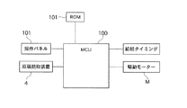
すなわち、この実施の形態に係るデジタルカラー複写機は、図4に示すように、空回転実行手段及び空回転時間制御手段としての機能を兼ね備えたMCU100を備えており、このMCU100は、定着装置36によって最大サイズよりも小さいサイズの記録用紙27を連続して定着した後、当該連続して定着したサイズの記録用紙27よりもサイズの大きな記録用紙27に未定着トナー像を定着する際に、加熱ロール51及び加圧ロール52の空回転を実行するとともに、当該空回転時間を次に定着処理を行う記録用紙27の画像情報に応じて制御するように構成されている。
That is, as shown in FIG. 4, the digital color copying machine according to this embodiment includes an
上記デジタルカラー複写機は、図5に示すように、最大サイズとしてA3サイズの記録用紙27に画像を形成可能となっているとともに、当該最大サイズであるA3サイズよりも小さいサイズ、例えば、B4サイズ、A4サイズ、B5サイズ、ハガキサイズなど、種々のサイズの用紙、あるいは同じサイズでも、厚紙やコート紙など異なる紙種の用紙に画像を形成することが可能となっている。
As shown in FIG. 5, the digital color copying machine can form an image on a
上記記録用紙27のサイズや紙種は、図4に示すように、MCU100に接続された操作パネル101によって指定され、同じく操作パネル101で指定された枚数だけ連続してコピーやプリントすることができるように構成されている。
As shown in FIG. 4, the size and paper type of the
また、上記記録用紙27は、図2に示すように、複数の給紙カセット29、30、31a、31b、あるいは手差しトレイ46から、すべて感光体ドラム14の軸方向に沿った中央部を基準(センターレジ)にして給紙され、定着装置36においても、図5に示すように、サイズの大小にかかわらず、加熱ロール51の軸方向に沿った中央部を基準(センターレジ)にして通紙され、定着処理が実行されるように構成されている。
Further, as shown in FIG. 2, the
それに対して、上記加熱ロール51の加熱源としてハロゲンランプ56は、当該加熱ロール56の全長に渡って配設されている。そのため、上記定着装置36では、最大サイズ以外の記録用紙27、例えば、A4サイズの記録用紙27を、SEF(Sort Edge Feed)で給紙し連続して定着処理を行った直後は、加熱ロール51の非通紙領域は、記録用紙27によって熱が消費されず蓄熱されるため、通紙領域と比較して温度が上昇することが知られている。
On the other hand, the
続けて、又は前回の定着処理終了後に所定時間以内に、上記定着装置36において次のジョブを開始すると、上記加熱ロール51には、次のジョブが開始する直前まで、ハロゲンランプ56が点灯されて、熱エネルギーが軸方向の全域に補充される。そのため、加熱ロール56の通紙領域は、図6に示すように、所定の設定温度まで上昇するが、加熱ロール56の非通紙領域は、当該所定の設定温度から大きく乖離して、 a程度まで上昇してしまうことになる。
When the next job is started in the fixing
この状態で、次のジョブ、連続して定着したサイズの用紙よりもサイズの大きな用紙に未定着トナー像を定着するジョブ、例えば最大サイズ(A3サイズ)の記録用紙27に定着するジョブを実行すると、加熱ロール51表面の温度ムラ( a)に応じて、画像品質に欠陥を生じるうえに、この状態を継続して画像形成動作を実行すると、加熱ロール51や加圧ロール52等の定着部材にも熱による欠陥が発生し、定着装置36の寿命を縮めることになる。
In this state, when a next job, a job for fixing an unfixed toner image on a paper having a size larger than a continuously fixed size paper, for example, a job for fixing to a maximum size (A3 size)
そこで、上記実施の形態では、次ジョブの前に、定着装置36の空回転動作を所定の空回転時間だけ実行して、図7に示すように、加熱ロール51の温度ムラを解消するように構成されている。ただし、上記加熱ロール51の空回転時間を長く設定する方が、加熱ロール51の表面温度を均一化する上では望ましい。しかし、加熱ロール51を空回転させる間は、次のジョブであるコピーやプリント動作等の画像形成動作を開始することができず待ち時間が長くなり、作業の効率性を阻害してしまうので、空回転時間は、可能な限り、最小限の時間に留める必要がある。
Therefore, in the above embodiment, before the next job, the idle rotation operation of the fixing
ところで、本発明者らは、加熱ロール51表面の温度ムラ( a)に起因して、画質欠陥が生じるメカニズムについて鋭意研究した結果、当該加熱ロール51表面の温度ムラ ( a)に起因した画質欠陥は、次のようにして発生すると考えられる。
By the way, as a result of intensive studies on the mechanism that causes image quality defects due to temperature unevenness (a) on the surface of the
上記加熱ロール51と加圧ロール52の定着ニップ部Nにおける著しい温度差( a)は、加熱ロール51等の回転部材の径を部分的に肥大化させて、当該加熱ロール51及び加圧ロール52の外径が、軸方向の中央部と両端部とにおけるニップ圧と周方向の線速度の間に大きな差を生じさせることになる。その結果、上記記録用紙27の搬送速度は、加熱ロール51等の両端部で速くなり過ぎ、加熱ロール51が記録用紙27表面のトナー像を擦ることなどによる画像ずれ等の画質ディフェクトが発生してしまうことになる。
The remarkable temperature difference (a) in the fixing nip N between the
特に、本発明者らが鋭意研究した結果で明らかとなったことは、記録用紙27の表面に発生する画質ディフェクトが、次に定着処理を行う記録用紙27上に定着される画像情報に依存するという事実である。例えば、次に定着処理を行う記録用紙27上に定着される画像情報である次原稿の画像濃度が薄い(記録用紙27上のトナー量が少ない)場合には、記録用紙27と加熱ロール51等との密着性が相対的に高く、加熱ロール51の搬送速度(線速度)の差が、記録用紙27の搬送に顕著に影響することになる。
In particular, what has become clear as a result of intensive studies by the present inventors is that the image quality defect occurring on the surface of the
これに対して、次に定着処理を行う記録用紙27上に定着される画像情報である次原稿の画像濃度が濃い(記録用紙27上のトナー量が多い)場合には、記録用紙27上のトナーが潤滑剤の役割を果し、記録用紙27と加熱ロール51等との間に滑りが生じて、記録用紙27の搬送力が低下する傾向にあることがわかった。
On the other hand, when the image density of the next original, which is image information to be fixed on the
そこで、この実施の形態では、図4に示すように、空回転実行手段を実行する機能に加えて、空回転時間制御手段としても機能するMCU100が、実行する空回転時間を、次に定着処理を行う用紙の画像情報に応じて制御するように構成されている。
Therefore, in this embodiment, as shown in FIG. 4, in addition to the function of executing the idling rotation execution means, the
更に説明すると、上記加熱ロール51の表面温度が不均一であることに起因する画質ディフェクトは、小サイズの記録用紙27を連続して定着処理した場合における、加熱ロール51の通紙領域と非通紙領域とで、記録用紙27の通紙に伴う熱の奪われ方に差があるために発生する。したがって、上記画質ディフェクトは、図8に示すように、小サイズの記録用紙27の連続した通紙枚数が少ないほど良好である(現われ難く)、小サイズの記録用紙27の連続した通紙枚数が多くなるに従って悪くなる(現われ易い)。なお、図では、便宜上、画質ディフェクトと通紙枚数との関係が直線(一次式)で表されているが、両者の関係は直線(一次式)に限らず、曲線(二次式や三次式など)で表される場合であっても良いことは勿論である。
More specifically, the image quality defect caused by the non-uniform surface temperature of the
この実施の形態では、MCU100は、次に定着処理を行う記録用紙27の平均画像密度、特定領域の画像情報、記録用紙27の搬送方向に沿った中間部から後端部の画像情報、記録用紙27の先端から搬送方向に沿って100mm以降の画像情報のうちの、少なくともいずれか1つに応じて空回転時間を制御するように構成されている。
In this embodiment, the
具体的には、次に定着処理を行う記録用紙27の画像情報として、例えば、当該記録用紙27の平均画像密度(単位面積あたりの画素数)が用いられ、記録用紙27の画像領域の全面に形成される画像の画素数を、記録用紙27の画像領域の面積で割った値が、記録用紙27の平均画像密度として使用される。その際、モノクロ等の単色の画像であれば、画像の有無によって画素数をカウントしても良いし、カラー画像であれば、イエロー(Y)、マゼンタ(M)、シアン(C)、ブラック(BK)の各色の画素数がカウントされる。例えば、同一の画像領域にイエロー(Y)とマゼンタ(M)の画像が重ねて形成される場合は、当該画像領域の画素数は2となる。また、上記画像を形成する際に、中間調を再現する場合には、濃度(例えば、256階調)に応じた分だけ係数を掛けて、画像領域の画素数が求められる。
Specifically, for example, the average image density (the number of pixels per unit area) of the
上記次に定着処理を行う記録用紙27の画像情報は、MCU100によって演算するように構成しても良いが、MCU100の負荷が大きくなり過ぎる場合は、画像処理装置11によって演算するように構成しても勿論良い。
The image information of the
上記MCU100が制御する空回転時間のデータとしては、例えば、図4に示すように、ROM101等にLUTとして記憶されているものが用いられるが、当該ROM101等に記憶されたLUTは、適宜、書き換え可能に構成しても良い。
As the idling time data controlled by the
このMCU100が制御する空回転時間は、大きくは、図9に示すように、次に定着処理を行う記録用紙27の画像情報として、画像濃度が濃いか、薄いか、中程度かに応じて、小サイズの記録用紙27の通紙枚数としては、少ないか、多いか、中程度かに応じて、加熱ロール51の空回転時間は、短いか、長いか、中程度かが決定される。
As shown in FIG. 9, the idling time controlled by the
そして、上記MCU100が制御する空回転時間は、図9に示すように、次に定着処理を行う記録用紙27の画像情報が濃い場合には、加熱ロール51の空回転時間が短く制御されるように、当該次に定着処理を行う記録用紙27の画像情報が中程度である場合には、加熱ロール51の空回転時間が中程度となるように、次に定着処理を行う記録用紙27の画像情報が薄い場合には、加熱ロール51の空回転時間が長くなるように、それぞれ制御される。
As shown in FIG. 9, the idling time controlled by the
一方、上記MCU100が制御する空回転時間は、図9に示すように、小サイズの記録用紙27の通紙枚数が少ない場合には、加熱ロール51の空回転時間が短く制御されるように、当該小サイズの記録用紙27の通紙枚数が中程度である場合には、加熱ロール51の空回転時間が中程度となるように、小サイズの記録用紙27の通紙枚数が多い場合には、加熱ロール51の空回転時間が長くなるように、それぞれ制御される。
On the other hand, as shown in FIG. 9, the idle rotation time controlled by the
また、上記MCU100が制御する空回転時間は、図9に示すように、次に定着処理を行う記録用紙27の画像情報が濃いが、小サイズの記録用紙27の通紙枚数が多い場合には、加熱ロール51の空回転時間が中程度となるか、又は長くなるように、あるいは当該次に定着処理を行う記録用紙27の画像情報が薄いが、小サイズの記録用紙27の通紙枚数が少ない場合には、加熱ロール51の空回転時間が中程度となるか、又は短くなるように制御される。
Further, as shown in FIG. 9, the idling time controlled by the
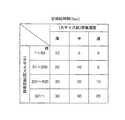
具体的には、上記MCU100は、図1に示すようなテーブルに基づいて、空回転時間を制御するように構成される。この図1に示すテーブルは、一例であり、これに限定されるものではないことは勿論である。
Specifically, the
上記の如く、MCU100は、次に定着処理を行う用紙の平均画像密度に応じて、空回転時間を決定して制御するが、これに限らず、MCU100は、特定領域の画像情報、用紙の搬送方向に沿った中間部から後端部の画像情報、用紙の先端から搬送方向に沿って100mm以降の画像情報のうちの、少なくともいずれか1つに応じて空回転時間を制御するように構成することも勿論可能である。
As described above, the
この場合、上記MCU100は、原稿読取装置4で読み取られた原稿の画像情報、あるいは図示しないパーソナルコンピュータ等から送られてくる画像情報に基づいて、原稿の特定領域の画像情報、例えば、原稿の中間部から後方に位置する画像情報であって、図10(a)に示すように、当該原稿の記録用紙27の搬送方向と直交する方向の両端部に位置する画像情報に基づいて、空回転時間を決定して制御するように構成される。その際、上記原稿の特定領域の画像情報として、例えば、原稿の中間部から後方に位置する画像情報であって、当該原稿の記録用紙27の搬送方向と直交する方向の両端部に位置する画像情報に着目するのは、図6に示すような加熱ロール51の軸方向に沿った温度の不均一に起因する画像ディフェクトは、記録用紙27の中間部から後方に位置する画像情報であって、当該記録用紙27の搬送方向と直交する方向の両端部に位置する画像に発生し易いからである。
In this case, the
また、上記デジタルカラー複写機では、原稿読取装置4で読み取る原稿の方向と、記録用紙27の搬送方向とは必ずしも一致しない場合があるが、本実施の形態では、加熱ロール51の軸方向に沿った温度の不均一によって画像ディフェクトが発生するため、画像情報を考慮する際は、記録用紙27の搬送方向に沿った領域に着目する必要がある。
In the digital color copying machine, the direction of the document read by the
さらに、上記MCU100は、図10(b)に示すように、次に定着処理を行う用紙の搬送方向に沿った中間部(例えば、中央を基準)から後端部の画像情報(平均画像濃度)に応じて、空回転時間を制御するように構成しても良い。
Further, as shown in FIG. 10B, the
また、上記MCU100は、図10(c)に示すように、次に定着処理を行う用紙の先端から搬送方向に沿って100mm以降の画像情報に応じて、空回転時間を制御するように構成しても良い。
Further, as shown in FIG. 10C, the
さらに、上記MCU100は、次に定着処理を行う用紙の画像情報として、平均画像密度に限らず、画像の構造についての情報を用いるように構成しても良い。この画像の構造情報としては、例えば、画像のドット処理、又は誤差拡散処理、あるいはスクリーン角度についての情報が挙げられる。
Further, the
前述したように、加熱ロール51の表面温度の不均一に起因した画像ディフェクトは、次に定着処理を行う用紙の画像情報に応じて、その現われ方が異なり、当該次に定着処理を行う用紙の画像情報である平均画像濃度が高い場合は、画像ディフェクトが現われ難いように、次に定着処理を行う用紙の画像の構造に応じても、その現われ方が異なる。
As described above, the image defect caused by the nonuniformity of the surface temperature of the
上記記録用紙27上の画像の構造としては、画像のドット処理や、誤差拡散処理など、種々の画像処理による画像構造が知られており、実際に使用されている。
As the structure of the image on the
上記デジタルカラー複写機において、写真画像などの中間調画像の再現性を挙げるためには、万線スクリーンやドットスクリーンなど、種々の構造のスクリーンが用いられており、しかもスクリーン線数も高画質化に伴って1200lpiや2400lpi等に増加する傾向にある。 In the above digital color copiers, screens with various structures such as line screens and dot screens are used to improve the reproducibility of halftone images such as photographic images, and the number of screen lines is also high. With this, it tends to increase to 1200 lpi, 2400 lpi, and the like.
また、上記ドットスクリーンにしても、より高画質化のために、誤差拡散処理などが用いられ、当該画像の構造によっても、記録用紙27上に形成されるトナー像のパターンが微視的に見た場合異なり、加熱ロール51の表面温度の不均一に起因した画像ディフェクトの現われる傾向が変化する。
Even in the case of the dot screen, error diffusion processing or the like is used for higher image quality, and the pattern of the toner image formed on the
そこで、上記MCU100は、次に定着処理を行う用紙の画像情報として、平均画像密度に限らず、画像の構造についての情報を用いるように構成しても良い。この画像の構造情報としては、上述したように、画像のドット処理、又は誤差拡散処理、あるいはスクリーン角度についての情報が挙げられる。
Therefore, the
例えば、図12に示すように、誤差拡散処理が施された画像構造については、ドット処理が施された画像構造と比較すると、同じ高い画像濃度を目標に出力されても、誤差配分から、実際の画像濃度はドット処理を施したものよりも低くなる傾向にあるため、ドット処理を施した場合に比べて空回転時間を若干長く行う必要がある。反対に薄い画像濃度を目標に出力された場合には、ドット処理を施した場合に比べて、空回転時間を若干短く行う制御が必要となる。 For example, as shown in FIG. 12, the image structure subjected to the error diffusion processing is actually compared with the error distribution even if the same high image density is output as compared with the image structure subjected to the dot processing. Since the image density tends to be lower than that subjected to dot processing, it is necessary to perform the idling time slightly longer than in the case where dot processing is performed. On the other hand, when a light image density is output as a target, it is necessary to perform control for slightly shortening the idling time as compared with the case where dot processing is performed.
以上の構成において、この実施の形態1に係るデジタルカラー複写機では、次のようにして、定着手段によって小サイズの用紙にトナー像を連続して定着した後に、大サイズの用紙にトナー像を定着する場合のように、非通紙領域で熱が消費されず蓄熱されることに伴う紙しわの発生や、定着性の不均一等が発生することを、適切な空回転時間を設定することによって防止でき、画像形成動作を開始するまでの無駄な待ち時間を短縮することが可能となっている。 In the above configuration, in the digital color copying machine according to the first embodiment, the toner image is continuously fixed on the small size paper by the fixing unit as described below, and then the toner image is applied on the large size paper. As in the case of fixing, setting an appropriate idling time to generate paper wrinkles due to heat being stored without being consumed in the non-sheet passing area, non-uniform fixing property, etc. The useless waiting time until the image forming operation is started can be shortened.
すなわち、上記デジタルカラー複写機では、図2に示すように、図示しない原稿を、自動原稿搬送装置(ADF)2によってプラテンガラス3上に自動的に搬送しつつ、当該図示しない原稿を、原稿読取装置4によって読み取るように構成されている。上記原稿読取装置4によって読み取られた原稿の画像情報は、画像処理装置11によって所定の画像処理を受ける。その後、上記画像処理装置11によって所定の画像処理を受けた画像情報は、ROS12に送られ、当該ROS12によって画像データに基づいて、感光体ドラム14上にレーザー光LBが走査露光され、感光体ドラム14の表面に静電潜像が形成される。そして、上記感光体ドラム14上に形成された静電潜像は、ロータリー方式の現像装置16のイエロー(Y)、マゼンタ(M)、シアン(C)、ブラック(BK)の4色の現像器16Y、16M、16C、16BKのうち、対応する色の現像器16Y、16M、16C、16BKによって順次現像され、トナー像となる。上記感光体ドラム14上に形成されたイエロー(Y)、マゼンタ(M)、シアン(C)、ブラック(BK)等の各色のトナー像は、中間転写ベルト21上に多重に一次転写された後、当該中間転写ベルト21から記録用紙27上に一括して二次転写された後、定着装置36へと搬送されて、記録用紙27上にフルカラー又はモノクロの画像が定着され、排出トレイ38上に排出される。
That is, in the digital color copying machine, as shown in FIG. 2, a document (not shown) is automatically conveyed onto the
その際、上記デジタルカラー複写機では、A4サイズやB5サイズ等の最大サイズであるA3サイズよりも小さいサイズの記録用紙27に、複数枚連続して画像が形成される場合があり、しかもその後に続けて当該A4サイズやB5サイズ等のサイズよりも大きい、A3サイズやB4サイズ等の記録用紙27に画像を定着する場合がある。
At that time, in the digital color copying machine, a plurality of images may be continuously formed on the
この場合、上記定着装置36の加熱ロール51の表面温度は、図11に示すように、加熱ロール51の軸方向に沿って全領域が、所定の定着温度に略等しい温度に加熱された状態となっている。この状態で、上記定着装置36において、上述したように、最大サイズであるA3サイズよりも小さいA4サイズの記録用紙27に、複数枚連続して定着処理を行うと、加熱ロール51等の非通紙領域では、記録用紙27によって加熱ロール51の熱が奪われないため、図6に示すように、当該加熱ロール51の非通紙領域の温度が aだけ異常に高くなる。
In this case, as shown in FIG. 11, the surface temperature of the
そこで、この実施の形態では、MCU100は、最大サイズであるA3サイズよりも小さいA4サイズの記録用紙27に、複数枚連続して定着処理を実行した後、次のジョブとして、当該A4サイズよりも大きい、A3サイズの記録用紙27への画像定着が指定されている場合には、直ちに次のジョブを開始せずに、加熱ロール51を所定の空回転時間だけ空回転させるようになっている。
Therefore, in this embodiment, the
また、上記MCU100は、加熱ロール51を所定の空回転時間だけ空回転させるとき、当該空回転時間を次に定着処理を行う記録用紙27の画像情報に応じて制御するようになっている。この場合、MCU100は、図1に示すように、定着処理を行う記録用紙27がA3サイズの用紙であって、当該A3サイズの記録用紙27の画像情報が、平均画像密度として薄いと判別すると、それに先立つA4サイズの記録用紙27の連続した通紙枚数に応じて、このA4サイズの記録用紙27の連続した通紙枚数が、1〜50枚である場合には、空回転時間を10(sec)に、51〜200枚である場合には、空回転時間を20(sec)に、それぞれ設定するようになっている。
Further, when the
その結果、上記MCU100は、加熱ロール51を空回転時間を、次に定着処理を行う記録用紙27の画像情報と、それに先立った最大サイズであるA3サイズよりも小さいA4サイズの記録用紙27の連続した通紙枚数の両方に応じて制御するように構成されているので、加熱ロール51を空回転時間を一定に固定した場合のように、画像ディフェクトの発生を防止することができるものの、加熱ロール51の空回転時間が長くなり、生産性が低下せざるを得ないという課題を解決することが可能となる。
As a result, the
特に、従来のデジタルカラー複写機等の画像形成装置では、生産性よりも画質が優先される傾向にあるため、画像ディフェクトが発生するのを確実に防止することを優先して、加熱ロール51の空回転時間が長く設定されることが多い。 In particular, in conventional image forming apparatuses such as digital color copying machines, image quality tends to be prioritized over productivity. The idling time is often set longer.
これに対して、この実施の形態に係るデジタルカラー複写機では、MCU100によって、加熱ロール51を空回転時間を、次に定着処理を行う記録用紙27の画像情報と、それに先立った最大サイズであるA3サイズよりも小さいA4サイズの記録用紙27の連続した通紙枚数や経過時間の両方に応じて制御するように構成されているので、加熱ロール51の空回転時間を適切に設定することができ、画像ディフェクトが発生するのを防止しつつ、次の画像形成動作を開始するまでの無駄な待ち時間を短縮することが可能となっている。その結果、上記デジタルカラー複写機では、画質の向上と、生産性の向上とを両立させることができるようになっている。
On the other hand, in the digital color copying machine according to this embodiment, the
27:記録用紙、36:定着装置、51:加熱ロール(加熱用回転部材)、100:MCU。 27: recording paper, 36: fixing device, 51: heating roll (rotating member for heating), 100: MCU.
Claims (9)
前記定着手段によって最大サイズよりも小さいサイズの用紙を連続して定着した後、当該連続して定着したサイズの用紙よりもサイズの大きな用紙に未定着トナー像を定着する際に、前記回転部材の空回転を実行する空回転実行手段と、
前記空回転実行手段が実行する空回転時間を、次に定着処理を行う用紙の画像情報に応じて制御する空回転時間制御手段とを備えたことを特徴とする画像形成装置。 An image forming apparatus including a fixing unit that fixes an unfixed toner image on a sheet by conveying the sheet on which the unfixed toner image is transferred while being sandwiched by a pair of rotating members each having a heating source. ,
After fixing a sheet of a size smaller than the maximum size continuously by the fixing unit, when fixing an unfixed toner image on a sheet having a size larger than the sheet of the size fixed continuously, the rotation member Idle rotation execution means for executing idle rotation;
An image forming apparatus comprising: an idle rotation time control unit that controls an idle rotation time executed by the idle rotation execution unit in accordance with image information of a sheet on which a fixing process is performed next.
Priority Applications (1)
| Application Number | Priority Date | Filing Date | Title |
|---|---|---|---|
| JP2006012111A JP2007193165A (en) | 2006-01-20 | 2006-01-20 | Image forming apparatus |
Applications Claiming Priority (1)
| Application Number | Priority Date | Filing Date | Title |
|---|---|---|---|
| JP2006012111A JP2007193165A (en) | 2006-01-20 | 2006-01-20 | Image forming apparatus |
Publications (1)
| Publication Number | Publication Date |
|---|---|
| JP2007193165A true JP2007193165A (en) | 2007-08-02 |
Family
ID=38448899
Family Applications (1)
| Application Number | Title | Priority Date | Filing Date |
|---|---|---|---|
| JP2006012111A Withdrawn JP2007193165A (en) | 2006-01-20 | 2006-01-20 | Image forming apparatus |
Country Status (1)
| Country | Link |
|---|---|
| JP (1) | JP2007193165A (en) |
Cited By (7)
| Publication number | Priority date | Publication date | Assignee | Title |
|---|---|---|---|---|
| US20130209120A1 (en) * | 2012-02-09 | 2013-08-15 | Shinichi Namekata | Image forming apparatus |
| US8731423B2 (en) | 2011-01-19 | 2014-05-20 | Kabushiki Kaisha Toshiba | Image forming apparatus and control device and control method of fixing device |
| JP2014174385A (en) * | 2013-03-11 | 2014-09-22 | Ricoh Co Ltd | Image forming apparatus |
| JP2018092038A (en) * | 2016-12-05 | 2018-06-14 | キヤノン株式会社 | Image heating device and image forming device |
| JP2018097030A (en) * | 2016-12-08 | 2018-06-21 | 株式会社リコー | Fixing device and image forming apparatus |
| CN108287458A (en) * | 2017-01-10 | 2018-07-17 | 株式会社东芝 | Image forming apparatus and control method |
| EP3385794A1 (en) | 2017-04-04 | 2018-10-10 | Ricoh Company Ltd. | Fixing device and image forming apparatus incorporating same |
-
2006
- 2006-01-20 JP JP2006012111A patent/JP2007193165A/en not_active Withdrawn
Cited By (14)
| Publication number | Priority date | Publication date | Assignee | Title |
|---|---|---|---|---|
| US8731423B2 (en) | 2011-01-19 | 2014-05-20 | Kabushiki Kaisha Toshiba | Image forming apparatus and control device and control method of fixing device |
| US20130209120A1 (en) * | 2012-02-09 | 2013-08-15 | Shinichi Namekata | Image forming apparatus |
| JP2013164446A (en) * | 2012-02-09 | 2013-08-22 | Ricoh Co Ltd | Image forming device |
| US9568868B2 (en) * | 2012-02-09 | 2017-02-14 | Ricoh Company, Limited | Image forming apparatus |
| JP2014174385A (en) * | 2013-03-11 | 2014-09-22 | Ricoh Co Ltd | Image forming apparatus |
| JP2018092038A (en) * | 2016-12-05 | 2018-06-14 | キヤノン株式会社 | Image heating device and image forming device |
| JP2018097030A (en) * | 2016-12-08 | 2018-06-21 | 株式会社リコー | Fixing device and image forming apparatus |
| CN108287458A (en) * | 2017-01-10 | 2018-07-17 | 株式会社东芝 | Image forming apparatus and control method |
| US10042302B2 (en) * | 2017-01-10 | 2018-08-07 | Kabushiki Kaisha Toshiba | Image forming apparatus and control method |
| US10295945B2 (en) | 2017-01-10 | 2019-05-21 | Kabushiki Kaisha Toshiba | Image forming apparatus and control method |
| US20190235433A1 (en) * | 2017-01-10 | 2019-08-01 | Kabushiki Kaisha Toshiba | Image forming apparatus and control method |
| US10571843B2 (en) | 2017-01-10 | 2020-02-25 | Kabushiki Kaisha Toshiba | Image forming apparatus and control method |
| US10852681B2 (en) | 2017-01-10 | 2020-12-01 | Kabushiki Kaisha Toshiba | Image forming apparatus and control method |
| EP3385794A1 (en) | 2017-04-04 | 2018-10-10 | Ricoh Company Ltd. | Fixing device and image forming apparatus incorporating same |
Similar Documents
| Publication | Publication Date | Title |
|---|---|---|
| JP3403057B2 (en) | Image forming device | |
| JP4994726B2 (en) | Image forming apparatus | |
| JP6135640B2 (en) | Image forming apparatus, image forming system, and density unevenness detection method | |
| JP2007193165A (en) | Image forming apparatus | |
| JP2005099333A (en) | Image forming apparatus | |
| JP4105168B2 (en) | Image forming apparatus | |
| JP7229461B2 (en) | Fixing device and image forming device | |
| JP2006078683A (en) | Image forming apparatus and its cooling method and program | |
| JP6125147B2 (en) | Image forming apparatus | |
| JP3605783B2 (en) | Image forming device | |
| JP2006047410A (en) | Image forming apparatus | |
| JP2011158598A (en) | Image forming apparatus | |
| US20060182473A1 (en) | Image forming device | |
| JP6733348B2 (en) | Image forming device | |
| JP2010151862A (en) | Image forming apparatus | |
| JP6620617B2 (en) | Image forming apparatus and conveyance control method | |
| JP2005164922A (en) | Image forming apparatus | |
| JP5135168B2 (en) | Image forming apparatus | |
| JP5078449B2 (en) | Image forming apparatus | |
| JP5268517B2 (en) | Image forming apparatus | |
| JP2007193361A (en) | Image forming apparatus | |
| JPH11202719A (en) | Image forming device | |
| JP6786991B2 (en) | Image forming device | |
| JP2007075907A (en) | Paper cutter and image forming apparatus including it | |
| JP2007058021A (en) | Image forming apparatus |
Legal Events
| Date | Code | Title | Description |
|---|---|---|---|
| A300 | Withdrawal of application because of no request for examination |
Free format text: JAPANESE INTERMEDIATE CODE: A300 Effective date: 20090407 |