JP2007192575A - Target positioning device - Google Patents
Target positioning device Download PDFInfo
- Publication number
- JP2007192575A JP2007192575A JP2006008801A JP2006008801A JP2007192575A JP 2007192575 A JP2007192575 A JP 2007192575A JP 2006008801 A JP2006008801 A JP 2006008801A JP 2006008801 A JP2006008801 A JP 2006008801A JP 2007192575 A JP2007192575 A JP 2007192575A
- Authority
- JP
- Japan
- Prior art keywords
- target
- signal
- sum
- beat
- frequency
- Prior art date
- Legal status (The legal status is an assumption and is not a legal conclusion. Google has not performed a legal analysis and makes no representation as to the accuracy of the status listed.)
- Pending
Links
Images
Landscapes
- Radar Systems Or Details Thereof (AREA)
Abstract
【課題】狭帯な受信機帯域で低速信号処理且つ高分解能を有し、送信局と受信局間の時刻の同期が必要なく、小口径のアンテナを備える小型の受信局からなり、運用が柔軟で低コストの目標測位装置を提供する。
【解決手段】目標測位装置は、送信局はFMCW電波を放射し、3つ以上の受信局は、FMCW電波と同様なローカル信号で直接波、または目標反射波をミキシングして直接ビート信号または目標反射ビート信号を求め、直接ビート信号の出力が最大になる直接波周波数を算出するとともに目標反射ビート信号の出力が最大になる目標反射波周波数を算出し、算出された直接波周波数と目標反射波周波数とに基づいて送信局と受信局との距離和と相対速度和とを推定し、目標位置・速度推定器は、距離和と相対速度和とから目標の3次元位置座標と3次元相対速度成分とを推定する。
【選択図】図1[PROBLEMS] To provide a low-speed signal processing and high resolution in a narrow receiver band, which does not require time synchronization between a transmitting station and a receiving station, and is composed of a small receiving station having a small-diameter antenna, and is flexible in operation. And provide a low-cost target positioning device.
The target positioning device includes a transmitting station that radiates FMCW radio waves, and three or more receiving stations that mix a direct wave or a target reflected wave with a local signal similar to the FMCW radio wave to generate a direct beat signal or target. Obtain the reflected beat signal, calculate the direct wave frequency that maximizes the output of the direct beat signal, calculate the target reflected wave frequency that maximizes the output of the target reflected beat signal, and calculate the calculated direct wave frequency and the target reflected wave Based on the frequency, the distance sum and the relative speed sum between the transmitting station and the receiving station are estimated, and the target position / speed estimator calculates the target 3D position coordinates and 3D relative speed from the distance sum and the relative speed sum. Estimate the components.
[Selection] Figure 1
Description
この発明は、送信アンテナと受信アンテナとが異なる地点に設置され、目標の物体の位置を測位する目標測位装置に関する。 The present invention relates to a target positioning device that is installed at a point where a transmission antenna and a reception antenna are different and measures the position of a target object.
バイスタティックレーダは、送信アンテナと受信アンテナとを異なる地点に設置し、目標の物体の位置を測位する。そして、目標の物体との距離を計測するために送信局と受信局間の時刻が同期されていなければならないので、ロラン(Long Range Navigation)電波を用いる時刻同期用のパルスを送信する、送信パルス周期、時刻、位相を示す送信パルス情報を生成し送受信する方法が採用されている(例えば、特許文献1、特許文献2参照)。
また、送信局と受信局間の時刻同期を行わず、受信局を複数を備え、直接波と目標反射波との相関処理により目標反射パルスの時間差を求め、複数の時刻差から目標の位置を特定する(例えば、特許文献3参照)。
Bistatic radars install a transmitting antenna and a receiving antenna at different points, and measure the position of a target object. Since the time between the transmitting station and the receiving station must be synchronized in order to measure the distance to the target object, a transmission pulse that transmits a pulse for time synchronization using a Loran (Long Range Navigation) radio wave is used. A method of generating and transmitting / receiving transmission pulse information indicating the period, time, and phase is employed (see, for example, Patent Document 1 and Patent Document 2).
In addition, time synchronization between the transmitting station and the receiving station is not performed, and there are a plurality of receiving stations. Specify (for example, refer to Patent Document 3).
しかし、送信局と受信局間の時刻を同期するためには、同期パルサや送信パルス情報を必要としており、高い距離精度を得るためには、広帯域の受信系と高速の信号処理が必要である。また、受信系において角度を高精度に計測するために開口径の大きい大規模な高価なアンテナが必要となるという問題がある。
また、受信局にて直接波パルスと目標反射パルスの時刻差を高精度に求めるためには、広帯域受信機と高速の相関処理が必要であり装置規模が大きくなるという問題がある。また、ドップラ周波数を利用した高精度な相対速度の計測ができないという問題がある。
However, in order to synchronize the time between the transmitting station and the receiving station, a synchronization pulser and transmission pulse information are required, and in order to obtain high distance accuracy, a wideband receiving system and high-speed signal processing are required. . In addition, there is a problem that a large-scale expensive antenna with a large aperture diameter is required to measure the angle with high accuracy in the receiving system.
In addition, in order to obtain the time difference between the direct wave pulse and the target reflected pulse with high accuracy at the receiving station, there is a problem that high-speed correlation processing with a broadband receiver is necessary and the device scale becomes large. In addition, there is a problem that it is impossible to measure the relative speed with high accuracy using the Doppler frequency.
この発明の目的は、狭帯な受信機帯域で低速信号処理且つ高分解能を有し、送信局と受信局間の時刻の同期が必要なく、小口径のアンテナを備える小型の受信局からなり、運用が柔軟で低コストの目標測位装置を提供することである。 The object of the present invention is a small receiver station having a low-speed signal processing and high resolution in a narrow receiver band, no need for time synchronization between the transmitter station and the receiver station, and a small-diameter antenna, It is to provide a target positioning device that is flexible in operation and low in cost.
この発明に係わる目標測位装置は、電波を放射する送信局、直接にまたは目標物体で反射してから到達する電波を受信する3つ以上の受信局および受信する電波に基づいて目標の位置と速度とを推定する目標位置・速度推定器を備える目標測位装置において、上記送信局は、送信FMCW信号を発生する送信FMCW信号発生器と、電波を上記送信FMCW信号により変調する送信信号変換器と、を備え、上記受信局は、上記FMCW信号と同様な掃引傾斜および掃引時間のローカル信号を発生する受信FMCW信号発生器と、上記送信局から受信される電波と上記ローカル信号とをミキシングしてビート信号を求める受信信号変換器と、上記ビート信号の出力が最大になるビート周波数と時刻誤差を算出する周波数分析手段と、上記ビート周波数と上記時刻誤差とに基づいて上記送信局と上記受信局との距離和と相対速度和とを推定する距離和速度和推定手段と、を備え、上記目標位置・速度推定器は、上記受信局から入力される上記距離和と上記時刻誤差とに基づいて上記目標の3次元位置座標を推定し、上記3次元位置座標と上記相対速度和とに基づいて上記目標の3次元相対速度成分を推定する。 The target positioning apparatus according to the present invention includes a transmitting station that radiates radio waves, three or more receiving stations that receive radio waves that arrive directly or after being reflected by a target object, and a target position and velocity based on the received radio waves. In the target positioning device including a target position / speed estimator for estimating the transmission FMCW signal generator, a transmission FMCW signal generator for generating a transmission FMCW signal, a transmission signal converter for modulating radio waves with the transmission FMCW signal, And the receiving station mixes the received FMCW signal generator for generating a local signal having the same sweep slope and sweep time as the FMCW signal, the radio wave received from the transmitting station and the local signal, and beats the received FMCW signal generator. A reception signal converter for obtaining a signal, a beat frequency at which the output of the beat signal is maximized, a frequency analysis means for calculating a time error, and the beat signal Distance sum speed sum estimating means for estimating a sum of distances and a relative speed sum between the transmitting station and the receiving station based on a wave number and the time error, and the target position / speed estimator includes the receiving position The target three-dimensional position coordinate is estimated based on the distance sum input from the station and the time error, and the target three-dimensional relative speed component is calculated based on the three-dimensional position coordinate and the relative speed sum. presume.
この発明に係わる目標測位装置の効果は、FMCW信号により変調された電波を用い、受信局の時刻を送信局の時刻に同期する必要がなく、同期パルサや送信パルス情報を必要としないので、狭帯域の受信系と低速の信号処理であっても高精度の位置分解能を実現でき、小型で移動可能な受信局となり、運用の柔軟性を確保できる。また、FMCW信号により変調された電波を用いているので、ドップラ現象を利用して高精度な相対速度の計測ができる。 The effect of the target positioning apparatus according to the present invention is that the radio wave modulated by the FMCW signal is used, it is not necessary to synchronize the time of the receiving station with the time of the transmitting station, and no synchronization pulser or transmission pulse information is required. Even with a band receiving system and low-speed signal processing, high-accuracy position resolution can be realized, and the receiving station can be made small and movable, thereby ensuring operational flexibility. In addition, since the radio wave modulated by the FMCW signal is used, the relative velocity can be measured with high accuracy using the Doppler phenomenon.
実施の形態1.
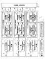
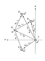
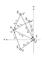
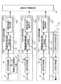
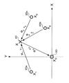
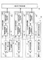
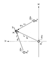
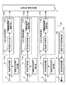
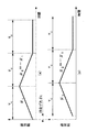
図1は、この発明の実施の形態1に係わる目標測位装置の構成図である。図2は、送信局、受信局および目標のXY座標面上の位置を示す図である。図3は、送信局および受信局でのFMCW信号の周波数の変化の様子を示す図である。
この発明の実施の形態1に係わる目標測位装置1は、図1に示すように、1つの送信局2、3つの受信局3a、3b、3cおよび目標位置・速度推定器4を備える。各受信局3a〜3cにおいて求められる距離和および相対速度和は一般的な通信手段を用いて目標位置・速度推定器4に送られる。なお、実施の形態1に係わる目標測位装置1は、3つの受信局3を備えるが、4つ以上の受信局3を備えてもよい。
Embodiment 1 FIG.
FIG. 1 is a configuration diagram of a target positioning apparatus according to Embodiment 1 of the present invention. FIG. 2 is a diagram illustrating the positions of the transmitting station, the receiving station, and the target on the XY coordinate plane. FIG. 3 is a diagram illustrating a change in frequency of the FMCW signal at the transmitting station and the receiving station.
A target positioning apparatus 1 according to Embodiment 1 of the present invention includes one transmitting
送信局2、受信局3a〜3cおよび目標20は、図2に示すように、配置されている。送信局2の座標をXYZ座標系の原点に置くと受信局3a〜3cの位置ベクトルはXnになる。nは受信局3a〜3cを識別する番号であり、3つの受信局3a〜3cが備えられているので、n=1、2、3である。この位置ベクトルXnは、既知である。目標20の位置ベクトルXは、この目標測位装置1により求める未知の値である。
また、図2におけるR0は、送信局2と目標20間の距離、Rnは、目標20と識別番号nの受信局3間の距離、R0nは、送信局2と識別番号nの受信局3間の距離である。
また、v0は、送信局2と目標20との相対速度、vnは、目標20と識別番号nの受信局3との相対速度、v0nは、送信局2と識別番号nの受信局3との相対速度である。
The transmitting
In FIG. 2, R 0 is the distance between the
V 0 is the relative speed between the
送信局2は、図1に示すように、送信Frequency Modulated Continuous Wave信号(以下、FMCW信号と略記する。)を発生する送信FMCW信号発生器5、送信FMCW信号発生器5から入力される送信FMCW信号に従って電波を変調する送信信号変換器6、電波を空中に放射する送信アンテナ7を備える。
送信FMCW信号発生器5は、送信信号変換器6において行われる周波数変調処理の周波数を指定する送信FMCW信号を発生する。送信FMCW信号は、図3(a)に示すように、中心周波数f、掃引帯域幅B、掃引時間TCであり、掃引傾斜が掃引時間TC毎にμ1=B/TCとμ2=−B/TCとに切り替わる。
As shown in FIG. 1, the
The transmission
送信信号変換器6は、送信FMCW信号により指定される周波数の連続波に変調して送信アンテナ7に出力する。そして、放射される電波Txiは、式(1)で表される。iは、掃引傾斜μ1または掃引傾斜μ2を識別する番号であり、1または2である。なお、説明を理解しやすくするためにエンベロープ1の一定振幅とした。
The
各受信局3a〜3cは、図1に示すように、空中を伝搬して到達する電波を受信する受信アンテナ8、受信FMCW信号に基づいてローカル信号を発生する受信FMCW信号発生器9、受信する電波にローカル信号をミキシングし、ローパスフィルターにより周波数の和信号を除去し、ビート信号を生成する受信信号変換器10、ビート信号を処理して距離和と相対速度和とを推定するFMCW信号処理器11を備える。
As shown in FIG. 1, each of the
受信アンテナ8には、送信アンテナ7から空中に放射された電波が直接または目標20の物体で反射してから到達する。以下の説明において目標20の物体で反射してから到達する電波を目標反射波、直接に到達する電波を直接波と称す。
目標反射波Rx1,nは、式(2)で表される。τ0は、時刻t=0での送信局2と目標20間の電波の伝搬時間であり、送信局2と目標20間の距離R0を用いると式(3)で表される。τnは、時刻t=0での目標20と識別番号nの受信局3間の電波の伝搬時間であり、目標20と識別番号nの受信局3間の距離Rnを用いると式(4)で表される。v0は、時刻t=0での送信局2と目標20との相対速度、vnは、時刻t=0での目標20と識別番号nの受信局3との相対速度である。cは光速である。
The radio wave radiated from the transmitting
The target reflected wave Rx 1, n is expressed by Expression (2). τ 0 is the propagation time of the radio wave between the
また、直接波Rx0i,nは、式(5)で表される。なお、直接波を目標反射波と区別する方法は,時分割して目標20がない時に計測したり、アンテナビームスキャンによる利得差を計測したりするなどにより区別する。なお、同時に観測されたとした場合も、送信局2と受信局3間の相対速度がある程度既知(たとえばともに静止しているなど)とすることで、目標反射波と直接波を分離可能である。以下の説明では、別個に受信したものとして説明する。
Further, the direct wave Rx0 i, n is expressed by Expression (5). Note that the direct wave is distinguished from the target reflected wave by time division and measuring when there is no
受信FMCW信号発生器9は、受信した電波を受信信号変換器10においてミキシングするためのローカル信号を生成する受信FMCW信号を生成し、その受信FMCW信号を用いてローカル信号を生成して受信信号変換器10に出力する。受信FMCW信号は、図3(b)に示すように、送信FMCW信号と同様に中心周波数f、掃引帯域幅B、掃引時間TCであり、掃引傾斜が掃引時間TC毎にμ1=B/TCとμ2=−B/TCとに切り替わる。但し、送信局2と受信局3との間には時刻ずれδtnがある。
受信FMCW信号発生器9が生成するローカル信号Li,nは、式(6)で表される。
The reception FMCW signal generator 9 generates a reception FMCW signal that generates a local signal for mixing the received radio wave in the
The local signal L i, n generated by the reception FMCW signal generator 9 is expressed by Expression (6).
受信信号変換器10は、目標反射波Rxi,nをローカル信号Li,nでミキシンングし、ローパスフィルターを通過して周波数の和信号が除去され、目標反射ビート信号Bi,nが得られる。目標反射ビート信号Bi,nは、式(7)で表される。なお、光速c比べて速度v0、vnは十分小さいと仮定している。
また、直接波Rx0i,nをローカル信号Li,nでミキシンングし、ローパスフィルターを通過して周波数の和信号が除去され、直接ビート信号B0i,nが得られる。直接ビート信号B0i,nは、式(8)で表される。
The
Further, the direct wave Rx0 i, n is mixed with the local signal L i, n , passes through the low-pass filter, the frequency sum signal is removed, and the direct beat signal B0 i, n is obtained. The direct beat signal B0 i, n is expressed by equation (8).
FMCW信号処理器11は、図1に示すように、周波数分析手段13としての目標反射波周波数分析手段14、直接波周波数分析手段15および時刻誤差推定手段16と距離和速度和推定手段17とを有する。
目標反射波周波数分析手段14は、目標反射ビート信号Bi,nをフーリエ変換し、出力がピークになる目標反射ビート周波数fi,n(バー)を、式(9)から求める。
As shown in FIG. 1, the FMCW signal processor 11 includes a target reflected wave frequency analysis unit 14, a direct wave
The target reflected wave frequency analyzing means 14 performs a Fourier transform on the target reflected beat signal B i, n and obtains a target reflected beat frequency f i, n (bar) at which the output reaches a peak from the equation (9).
直接波周波数分析手段15は、直接ビート信号B0i,nをフーリエ変換し、出力がピークになる直接ビート周波数f0i,n(バー)を、式(10)から求める。 The direct wave frequency analyzing means 15 performs a Fourier transform on the direct beat signal B0 i, n and obtains a direct beat frequency f0 i, n (bar) at which the output reaches a peak from the equation (10).
時刻誤差推定手段16は、検出された目標反射ビート周波数fi,n(バー)と直接ビート周波数f0i,n(バー)を用いて、式(11)から送信局2と各受信局3a〜3bの間の時刻誤差δtn(ハット)を求める。
The time error estimating means 16 uses the detected target reflection beat frequency f i, n (bar) and the direct beat frequency f0 i, n (bar) to calculate the transmitting
距離和速度和推定手段17は、送信局2と各受信局3a〜3bの間の時刻誤差δtn(ハット)を用いて、式(12)から送信局2と目標20および目標20と各受信局3a〜3c間の距離和ξn(ハット)を求める。
式(12)において、周波数μ1、μ2は設定値であり、目標反射ビート周波数f1,n(バー)、目標反射ビート周波数f2,n(バー)、時刻誤差δtn(ハット)はフーリエ変換により求められている。そして、送信局2と各受信局3間の距離R0nは既知であるので、時間遅延τ0nは既知となり、式(12)から距離和ξn(ハット)が求められる。
The distance sum speed sum estimating means 17 uses the time error δt n (hat) between the transmitting
In Expression (12), the frequencies μ 1 and μ 2 are set values, and the target reflection beat frequency f 1, n (bar), the target reflection beat frequency f 2, n (bar), and the time error δt n (hat) are It is obtained by Fourier transform. Since the distance R 0n between the transmitting
また、距離和速度和推定手段17は、時刻誤差δtn(ハット)、距離和ξn(ハット)および目標反射ビート周波数f1,n(バー)を用いて、各受信局3a〜3cでの送信局2と目標20および目標20と各受信局3a〜3c間の相対速度和Vn(ハット)を式(13)から求める。
Further, the distance sum speed sum estimating means 17 uses the time error δt n (hat), the distance sum ξ n (hat) and the target reflection beat frequency f 1, n (bar), at each of the receiving
目標位置・速度推定器4は、以下の手順により目標20の3次元座標と3次元相対速度成分を推定する。
既知の送信局2の位置ベクトル、既知の各受信局3の位置ベクトルおよび推定対象の未知の目標20の位置ベクトルは、それぞれX0、Xn、Xであるので、式(12)の距離和ξnを用いることにより、式(14)の関係式が成り立つ。
そして、目標20の位置ベクトルXの推定値X(ハット)は、3つの受信局3a〜3cでの距離和ξn(ハット)を用いて、共役勾配法、準Newton法、Levenberg−Marquardt法などの一般的な非線形手法を用いて求められる。
また、目標20の相対速度ベクトルをVとすると、式(13)の線形方程式は式(15)に書き直せる。
そして、目標20の相対速度ベクトルVの推定値V(ハット)は、3つの受信局3a〜3cでの相対速度和Vn(ハット)と推定値X(ハット)から、逆行列や一般逆行列を用いて求められる。
The target position / speed estimator 4 estimates the three-dimensional coordinates and the three-dimensional relative speed component of the
Since the position vector of the known transmitting
Then, the estimated value of the position vector X of the target 20 X (hat), using the distance sum xi] n (hat) at three receiving
If the relative velocity vector of the
Then, the estimated value V (hat) of the relative velocity vector V of the
このような目標測位装置1は、電波としてFMCW電波を用い、3つ以上の受信局を備えており、受信局3の時刻を送信局2の時刻に同期する必要がなく、同期パルサや送信パルス情報を必要としないので、狭帯域の受信系と低速の信号処理系であっても高精度の位置分解能を実現でき、小型で移動可能な受信局3となり、運用の柔軟性を確保できる。また、FMCW電波を用いているので、ドップラ現象を利用して高精度な相対速度の推定ができる。
Such a target positioning device 1 uses FMCW radio waves as radio waves, and includes three or more receiving stations. The target positioning device 1 does not need to synchronize the time of the receiving station 3 with the time of the transmitting
なお、送信局2が送信機能とともに受信機能を有するときには、3つの受信局3の1つを送信局2に負わせることができるので、受信局3は2つでよい。
また、目標20の位置座標および相対速度の推定を水平面座標上の2次元推定を行うときには、受信局3を2つとしてもよい。
また、受信局3が2つのときに、式(13)で求めた2つの距離和ξnを用い、目標位置・速度推定器4では、回転楕円体の交点として目標20の位置を測位することも可能である。すなわち、目標20は送信局2と受信局3とを焦点とした距離和ξnの2つの回転楕円体の交点に存在するが、水平面座標を正とするなどの制約条件を付加することで、2つの回転楕円体の交点の中で目標20の位置として妥当な解を選択することにより目標20の位置座標を推定できる。
Note that when the transmitting
Further, when the two-dimensional estimation on the horizontal plane coordinates is performed for estimating the position coordinates and relative speed of the
When the number of receiving stations 3 is two, the target position / velocity estimator 4 uses the two distance sums ξ n obtained by the equation (13) to measure the position of the
また、FMCWをパルス化したFMパルス(FMICW(FM Interrupted CW)とも呼ばれる。)とし、距離ゲート化により、更なる狭帯域、直接波と目標反射波の分離、多目標の分離、近距離クラッタの回避などができる。 In addition, FM pulses (also referred to as FMICW (FM Interrupted CW)) obtained by pulsing the FMCW, and distance gating, further narrowband, separation of direct and target reflected waves, separation of multiple targets, short-range clutter It can be avoided.
実施の形態2.
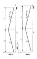
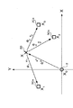
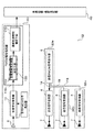
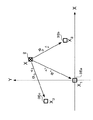
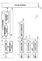
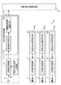
図4は、この発明の実施の形態2に係わる目標測位装置の構成図である。図5は、送信局、受信局および目標のXY座標面上の位置を示す図である。
この発明の実施の形態2に係わる目標測位装置1Bは、実施の形態1に係わる目標測位装置1と送信局2Ba〜2Bcと受信局3Bの局数が異なっており、それ以外は同様であるので、同様な部分に同じ符号を付記して説明は省略する。
実施の形態2に係わる目標測位装置1Bは、図4に示すように、3つの送信局2Ba〜2Bcと1つの受信局3Bとを備える。なお、実施の形態2に係わる目標測位装置1Bは、3つの送信局2Ba〜2Bcを備えるが、4つ以上の送信局を備えても同様な効果が得られる。
FIG. 4 is a configuration diagram of a target positioning apparatus according to
The target positioning device 1B according to the second embodiment of the present invention is the same as the target positioning device 1 according to the first embodiment except that the number of transmitting stations 2Ba to 2Bc and the number of receiving
As shown in FIG. 4, the target positioning apparatus 1B according to the second embodiment includes three transmitting stations 2Ba to 2Bc and one receiving
送信局2Ba〜2Bc、受信局3Bおよび目標20は、図5に示すように、配置されている。受信局3Bの座標をXYZ座標系の原点に置くと送信局2Ba〜2Bcの位置ベクトルはXnになる。nは送信局2Ba〜2Bcを識別する番号であり、3つの送信局2Ba〜2Bcが備えられているので、n=1、2、3である。この位置ベクトルXnは、既知である。目標20の位置ベクトルXは、この目標測位装置1Bにより求める未知の値である。
The transmitting stations 2Ba to 2Bc, the receiving
各送信局2Ba〜2Bcからは、3つの目標反射波を分離するために、送信を時分割している。なお、送信局2Ba〜2Bc毎に異なる中心周波数のFMCW信号の電波を放射し、受信局3Bの受信信号変換器10でそれぞれのFMCW信号のローカル信号に対しミキシングしてもよい。
From each of the transmission stations 2Ba to 2Bc, transmission is time-divided in order to separate the three target reflected waves. Note that radio waves of FMCW signals having different center frequencies may be emitted for each of the transmission stations 2Ba to 2Bc, and the local signal of each FMCW signal may be mixed by the
FMCW信号処理器11は、図4に示すように、周波数分析手段13Bとしての目標反射波周波数分析手段14、直接波周波数分析手段15および時刻誤差推定手段16と距離和速度和推定手段17とを有する。
各送信局2Ba〜2Bcと受信局3BとのFMCW信号の時刻誤差に起因する位相誤差δtnとすると、目標反射ビート信号Bi,nは、式(7)と同様に表される。
そして、目標反射波周波数分析手段14は、実施の形態1と同様にして、目標反射ビート信号Bi,nをフーリエ変換し、出力がピークになる目標反射ビート周波数fi,n(バー)を式(9)から求める。
As shown in FIG. 4, the FMCW signal processor 11 includes a target reflected wave frequency analyzing means 14, a direct wave frequency analyzing means 15, a time error estimating means 16, and a distance sum speed sum estimating means 17 as frequency analyzing means 13B. Have.
Assuming that the phase error δt n caused by the time error of the FMCW signal between each of the transmitting stations 2Ba to 2Bc and the receiving
Then, the target reflected wave frequency analyzing means 14 performs the Fourier transform on the target reflected beat signal B i, n in the same manner as in the first embodiment , and obtains the target reflected beat frequency f i, n (bar) at which the output reaches a peak. It calculates | requires from Formula (9).
また、直接波周波数分析手段15は、実施の形態1と同様にして、直接ビート信号B0i,nをフーリエ変換し、出力がピークになる直接ビート周波数f0i,n(バー)を式(10)から求める。 Similarly to the first embodiment, the direct wave frequency analyzing means 15 performs a Fourier transform on the direct beat signal B0 i, n to obtain a direct beat frequency f0 i, n (bar) at which the output reaches a peak (10). )
このようにして求められた目標反射ビート周波数fi,n(バー)、直接ビート周波数f0i,n(バー)を用いて、実施の形態1と同様に、目標20の位置ベクトルの推定値X(ハット)、相対速度ベクトルの推定値V(ハット)を推定することができる。
Using the target reflection beat frequency f i, n (bar) and the direct beat frequency f0 i, n (bar) obtained in this way, the estimated value X of the position vector of the
このような目標測位装置1Bは、送信局2を3つ以上備えれば、実施の形態1と同様に、受信局3の時刻を送信局2の時刻に同期する必要がなく、同期パルサや送信パルス情報を必要としないので、狭帯域の受信系と低速の信号処理系であっても高精度の位置分解能を実現でき、小型で移動可能な受信局3となり、運用の柔軟性を確保できる。
なお、送信局数が2であっても、2つの距離和ξnから回転楕円体の交点を求めることで目標20の位置座標を推定可能である。
If such a target positioning apparatus 1B includes three or
Even if the number of transmitting stations is 2, the position coordinates of the
実施の形態3.
図6は、この発明の実施の形態3に係わる目標測位装置の構成図である。図7は、送信局、受信局および目標のXY座標面上の位置を示す図である。
この発明の実施の形態3に係わる目標測位装置1Cは、図6に示すように、実施の形態1に係わる目標測位装置1の3つの受信局3a〜3cの受信信号変換器10に共通の受信FMCW信号発生器9からローカル信号が供給され、それに伴ってFMCW信号処理器11Cが異なっており、それ以外は同様であるので、同様な部分に同じ符号を付記して説明は省略する。
実施の形態3に係わる周波数分析手段13Cは、実施の形態1に係わる周波数分析手段13から直接波周波数分析手段15および時刻誤差推定手段16が削除されている。
Embodiment 3 FIG.
FIG. 6 is a block diagram of a target positioning apparatus according to Embodiment 3 of the present invention. FIG. 7 is a diagram showing the positions of the transmitting station, the receiving station, and the target on the XY coordinate plane.
As shown in FIG. 6, the target positioning device 1C according to the third embodiment of the present invention receives signals common to the
In the
実施の形態3に係わる目標測位装置1Cでは、図7に示すように、目標反射波だけを受信する。
各受信局3Ca〜3Ccには、1つの受信FMCW信号発生器9から受信FMCW信号がケーブル長の違いによる遅延などを補正して位相が一定値となるよう調整されながらケーブル18で接続されている。
The target positioning apparatus 1C according to the third embodiment receives only the target reflected wave as shown in FIG.
Each receiving station 3Ca-3Cc is connected by a
この実施の形態3に係わる受信FMCW信号は、各受信局3Ca〜3Cc間で位相が揃っているので、送信局2と各受信局3Ca〜3Ccの時刻誤差δtnは等しく、時刻誤差δtとなる。従って、各受信局3Ca〜3Ccでの受信信号変換器10でミキシングされた後の目標反射ビート信号Bi,nは、式(16)で表される。
Since the received FMCW signal according to the third embodiment has the same phase between the receiving stations 3Ca to 3Cc, the time error δt n of the transmitting
目標反射波周波数分析手段14Cは、目標反射ビート信号Bi,nをフーリエ変換し、出力がピークになる目標反射ビート周波数fi,n(バー)を式(17)から求める。
距離和速度和推定手段17Cは、検出した目標反射ビート周波数fi,n(バー)を用いて式(18)から送信局2と目標20間と目標20と各受信局3Ca〜3Cc間の時刻誤差δtを含む距離和ξn(ハット)を求める。
また、距離和速度和推定手段17Cは、式(19)から相対速度和Vn(ハット)を求める。
The target reflected wave frequency analyzing means 14C performs a Fourier transform on the target reflected beat signal B i, n and obtains a target reflected beat frequency f i, n (bar) at which the output reaches a peak from the equation (17).
The distance sum speed sum estimating means 17C uses the detected target reflection beat frequency f i, n (bar) to calculate the time between the transmitting
The distance sum speed sum estimating means 17C obtains the relative speed sum V n (hat) from the equation (19).
目標位置・速度推定器4Cは、以下の手順により目標20の3次元座標と3次元相対速度成分を推定する。
既知の送信局2の位置ベクトル、既知の各受信局3の位置ベクトルおよび推定対象の未知の目標20の位置ベクトルを、それぞれX0、Xn、Xとすると、式(18)の距離和ξnを用いることにより、時刻誤差δtを消去可能な式(20)〜式(22)が成り立つ。
そして、目標20の位置ベクトルXの推定値X(ハット)は、3つの受信局3Ca〜3Ccでの距離和ξn(ハット)を用いて、共役勾配法、準Newton法、Levenberg−Marquardt法などの一般的な非線形手法を用いて求められる。
The target position /
If the position vector of the known transmitting
Then, the estimated value X (hat) of the position vector X of the
また、目標20の相対速度ベクトルをVとすると、式(19)の線形方程式は式(23)に書き直せる。
そして、目標20の相対速度ベクトルVの推定値V(ハット)は、3つの受信局3での相対速度和Vn(ハット)と推定値X(ハット)を用いて、逆行列や一般逆行列を用いて求められる。
If the relative velocity vector of the
Then, the estimated value V (hat) of the relative velocity vector V of the
このような目標測位装置1Cは、各受信局3Ca〜3Ccへの受信FMCW信号間に時刻誤差の差異が発生しないので、直接波を計測する必要がなくなる。
なお、複数の受信FMCW信号を備え、それらが時刻同期している構成でも同様である。
Such a target positioning apparatus 1C does not need to measure a direct wave because there is no time error difference between the received FMCW signals to the receiving stations 3Ca to 3Cc.
The same applies to a configuration in which a plurality of received FMCW signals are provided and they are time synchronized.
実施の形態4.
図8は、この発明の実施の形態4に係わる目標測位装置の構成図である。図9は、送信局、受信局および目標のXY座標面上の位置を示す図である。
この発明の実施の形態4に係わる目標測位装置1Dは、実施の形態2に係わる目標測位装置1Bと送信FMCW信号が同期されて供給され、それにともなってFMCW信号処理器11Dが異なっており、それ以外は同様であるので、同様な部分に同じ符号を付記して説明は省略する。
実施の形態4に係わる目標測位装置1Dは、3つの送信局2Da〜2Dcと1つの受信局3Dとを備える。なお、実施の形態4に係わる目標測位装置1Dは、3つの送信局2Da〜2Dcを備えるが、4つ以上の送信局を備えても同様な効果が得られる。
各送信局2Da〜2Dcには、1つの送信FMCW信号発生器5から送信FMCW信号がケーブル長の違いによる遅延などを補正して位相が一定値となるよう調整されながらケーブル18で接続されている。また、各送信局2Da〜2Dcからは、目標反射波を分離するために、送信を時分割している。
Embodiment 4 FIG.
FIG. 8 is a block diagram of a target positioning apparatus according to Embodiment 4 of the present invention. FIG. 9 is a diagram illustrating the positions of the transmitting station, the receiving station, and the target on the XY coordinate plane.
The target positioning device 1D according to the fourth embodiment of the present invention is supplied with the target positioning device 1B according to the second embodiment synchronized with the transmission FMCW signal, and accordingly, the
A target positioning apparatus 1D according to the fourth embodiment includes three transmitting stations 2Da to 2Dc and one receiving
Each transmission station 2Da to 2Dc is connected by a
この実施の形態4に係わる送信FMCW信号は、各送信局2Da〜2Dc間で位相が揃っているので、各送信局2Da〜2Dcと受信局3Dの時刻誤差δtnは等しく、時刻誤差δtとなる。従って、受信局3Dの受信信号変換器10でミキシングされた後の目標反射ビート信号Bi,nは、式(16)で表される。
Since the transmission FMCW signal according to the fourth embodiment has the same phase between the transmission stations 2Da to 2Dc, the time error δt n of each of the transmission stations 2Da to 2Dc and the
実施の形態4に係わる周波数分析手段13Dは、実施の形態2に係わる周波数分析手段13Bから直接波周波数分析手段15および時刻誤差推定手段16が削除されている。
目標反射波周波数分析手段14Dは、目標反射ビート信号Bi,nをフーリエ変換し、出力がピークになる目標反射ビート周波数fi,n(バー)を式(17)から求める。
In the
The target reflected wave frequency analyzing means 14D performs a Fourier transform on the target reflected beat signal B i, n and obtains a target reflected beat frequency f i, n (bar) at which the output reaches a peak from the equation (17).
距離和速度和推定手段17Dは、検出した目標反射ビート周波数fi,n(バー)を用いて式(18)から各送信局2と目標20間と目標20と受信局3間の時刻誤差δtを含む距離和ξn(ハット)を求める。
また、距離和速度和推定手段17Dは、式(19)から相対速度和Vn(ハット)を求める。
The distance sum speed sum estimating means 17D uses the detected target reflection beat frequency f i, n (bar) to calculate the time error δt between each transmitting
The distance sum speed sum estimating means 17D obtains the relative speed sum V n (hat) from the equation (19).
目標位置・速度推定器4Dは、以下の手順により目標20の3次元座標と3次元相対速度成分を推定する。
既知の受信局3Dの位置ベクトル、既知の各送信局2Da〜2Dcの位置ベクトルおよび推定対象の未知の目標20の位置ベクトルを、それぞれX0、Xn、Xとすると、式(18)の距離和ξnを用いることにより、時刻誤差δtが消去可能な式(20)〜式(22)が成り立つ。
そして、目標20の位置ベクトルXの推定値X(ハット)は、3つの送信局2Da〜2Dcからの距離和ξn(ハット)を用いて、共役勾配法、準Newton法、Levenberg−Marquardt法などの一般的な非線形手法を用いて求められる。
The target position /
When the position vector of the known receiving
Then, the estimated value X (hat) of the position vector X of the
また、目標20の相対速度ベクトルをVとすると、式(19)の線形方程式は式(23)に書き直せる。
そして、目標20の相対速度ベクトルVの推定値V(ハット)は、3つの送信局2Da〜2Dcでの相対速度和Vn(ハット)と推定値X(ハット)を用いて、逆行列や一般逆行列を用いて求められる。
If the relative velocity vector of the
Then, the estimated value V (hat) of the relative velocity vector V of the
このような目標測位装置1Dは、各送信局2Da〜2Dcへの送信FMCW信号間に時刻誤差の差異が発生しないので、直接波を計測する必要がなくなる。
なお、複数の送信FMCW信号を備え、それらが時刻同期している構成でも同様である。
Such a target positioning apparatus 1D does not need to measure a direct wave because there is no time error difference between the FMCW signals transmitted to the transmitting stations 2Da to 2Dc.
The same applies to a configuration in which a plurality of transmission FMCW signals are provided and they are time synchronized.
実施の形態5.
図10は、この発明の実施の形態5に係わる目標測位装置の構成図である。図11は、目標である送信局および受信局のXY座標面上の位置を示す図である。
この発明の実施の形態5に係わる目標測位装置1Eは、1つの送信局2、3つの受信局3Ea〜3Ecおよび目標位置・速度推定器4Eを備え、送信局2の位置と相対速度とを推定する。各受信局3Ea〜3Ecにて求められる距離和および相対速度和は通信手段を用いて目標位置・速度推定器4Eに送られる。なお、実施の形態5に係わる目標測位装置1Eは、3つの受信局3Ea〜3Ecを備えるが、4つ以上の受信局を備えても同様な効果が得られる。
FIG. 10 is a block diagram of a target positioning apparatus according to
A
また、実施の形態5に係わる目標測位装置1Eでは、3つの受信局3Ea〜3Ecの受信信号変換器10に共通の受信FMCW信号発生器9から受信FMCW信号が供給されている。各受信局3Ea〜3Ecには、1つの受信FMCW信号発生器9から受信FMCW信号がケーブル長の違いによる遅延などを補正して位相が一定値となるよう調整されながらケーブル18で接続されている。この実施の形態5に係わる受信FMCW信号は、各受信局3Ea〜3Ec間で位相が揃っているので、送信局2と各受信局3Ea〜3Ecの時刻誤差δtnは等しく、時刻誤差δtとなる。
In the
送信局2は、実施の形態1に係わる送信局2と同様であるので、説明は省略する。そして、放射される電波Txiは、式(24)で表される。
Since the transmitting
受信局3Ea〜3Ecは、それぞれ、空中を伝搬して到達する電波を受信する受信アンテナ8、受信する電波に受信FMCW信号をミキシングし、ローパスフィルターにより周波数の和信号を除去し、ビート信号を生成する受信信号変換器10、ビート信号を処理して距離和と相対速度和とを推定するFMCW信号処理器11Eを備える。また、受信局3Eaは、受信FMCW信号を発生する受信FMCW信号発生器9を備え、受信信号変換器10にはケーブル18が接続されている。
Each of the receiving stations 3Ea to 3Ec receives a radio wave that arrives by propagating through the air, mixes the received FMCW signal with the received radio wave, removes a sum signal of frequencies by a low-pass filter, and generates a beat signal A
受信アンテナ8には、送信アンテナ7から空中に放射された電波が直接に到達する。以下の説明において、直接に到達する電波を直接波と称す。直接波Rx0i,nは、式(25)で表される。なお、τ0nは、送信局と受信局間を電波が伝搬する伝搬時間であり、送信局と受信局間の距離R0nと式(26)の関係式が成り立つ。
The radio wave radiated from the transmitting
受信FMCW信号発生器9は、受信した直接波を受信信号変換器10においてミキシングするためのローカル信号を生成する受信FMCW信号を生成し、その受信FMCW信号を用いてローカル信号を生成して受信信号変換器10に出力する。
受信FMCW信号発生器9が生成するローカル信号Li,nは、式(27)で表される。
The reception FMCW signal generator 9 generates a reception FMCW signal that generates a local signal for mixing the received direct wave in the
The local signal L i, n generated by the reception FMCW signal generator 9 is expressed by Expression (27).
受信信号変換器10は、直接波Rx0i,nをローカル信号Li,nでミキシンングし、ローパスフィルターを通過して周波数の和信号が除去され、直接ビート信号B0i,nが得られる。直接ビート信号B0i,nは、式(28)で表される。
The
FMCW信号処理器11Eは、周波数分析手段13Eとしての直接波周波数分析手段15および距離和速度和推定手段17Eを有する。
直接波周波数分析手段15Eは、直接ビート信号B0i,nをフーリエ変換し、出力がピークになる直接ビート周波数f0i,n(バー)を式(29)から求める。
The
The direct wave frequency analyzing means 15E performs a Fourier transform on the direct beat signal B0 i, n and obtains a direct beat frequency f0 i, n (bar) at which the output reaches a peak from the equation (29).
距離和速度和推定手段17Eは、検出した直接ビート周波数f0i,n(バー)を用いて、式(30)から送信局2と目標20間と目標20と各受信局3間の時刻誤差δtを含む距離和ξn(ハット)を求める。
また、距離和速度和推定手段17Eは、式(31)から相対速度和Vn(ハット)を求める。
The distance sum speed sum estimation means 17E uses the detected direct beat frequency f0 i, n (bar) to calculate the time error δt between the transmitting
Further, the distance sum speed sum estimating means 17E obtains the relative speed sum Vn (hat) from the equation (31).
目標位置・速度推定器4Eは、以下の手順により目標である送信局2の3次元座標と3次元相対速度成分とを推定する。
推定対象の未知の送信局2Eの位置ベクトルおよび既知の各受信局3の位置ベクトルを、それぞれX、Xnとすると、式(30)の距離和ξnを用いることにより、時刻誤差δtが消去される式(32)〜式(34)の関係式が成り立つ。
そして、送信局2の位置ベクトルXの推定値X(ハット)は、3局の受信局3Ea〜3Ecでの距離和ξn(ハット)を用いて、共役勾配法、準Newton法、Levenberg−Marquardt法などの一般的な非線形手法を用いて求められる。
The target position /
Assuming that the position vector of the unknown transmitting station 2E to be estimated and the position vector of each known receiving station 3 are X and Xn , respectively, the time error δt is eliminated by using the distance sum ξ n of equation (30). The following relational expressions (32) to (34) hold.
Then, the estimated value X (hat) of the position vector X of the transmitting
また、送信局2の相対速度ベクトルをVとすると、相対速度ベクトルVは、式(35)の関係式が成り立つ。
そして、送信局2の相対速度ベクトルVの推定値V(ハット)は、3つの受信局3Ea〜3Ecでの相対速度和Vn(ハット)と推定値X(ハット)を用いて、逆行列や一般逆行列を用いて求められる。
Further, when the relative velocity vector of the transmitting
Then, the estimated value V (hat) of the relative velocity vector V of the transmitting
このような目標測位装置1Eは、推定する対象の目標が送信局2である運用形態においても、実施の形態1と同様に、受信局3Ea〜3Ecの時刻を送信局2の時刻に同期する必要がなく、同期パルサや送信パルス情報を必要としないので、狭帯域の受信系と低速の信号処理系であっても高精度の位置分解能を実現でき、小型で移動可能な受信局3Ea〜3Ecとなり、運用の柔軟性を確保できる。
Such a
実施の形態6.
図12は、この発明の実施の形態6に係わる目標測位装置の構成図である。図13は、目標である受信局および送信局のXY座標面上の位置を示す図である。
この発明の実施の形態6に係わる目標測位装置1Fは、3つの送信局2Fa〜2Fc、1つの受信局3Fおよび目標位置・速度推定器4Fを備え、受信局3Fの位置と相対速度とを推定する。受信局3Fにて求められる距離和および相対速度和は通信手段を用いて目標位置・速度推定器4Fに送られる。なお、実施の形態6に係わる目標測位装置1Fは、3つの送信局2Fa〜2Fcを備えるが、4つ以上の送信局を備えても同様な効果が得られる。
FIG. 12 is a block diagram of a target positioning apparatus according to
A target positioning apparatus 1F according to
また、実施の形態6に係わる目標測位装置1Fでは、3つの送信局2Fa〜2Fcの送信信号変換器6に共通の送信FMCW信号発生器5から送信FMCW信号が供給されている。各送信局2Fa〜2Fcには、1つの送信FMCW信号発生器5から送信FMCW信号がケーブル長の違いによる遅延などを補正して位相が一定値となるよう調整されながらケーブル18で接続されている。この実施の形態6に係わる送信FMCW信号は、各送信局2Fa〜2Fc間で位相が揃っているので、送信局2Fa〜2Fcと受信局3Fの時刻誤差δtnは等しく、時刻誤差δtとなる。
In the target positioning apparatus 1F according to the sixth embodiment, the transmission FMCW signal is supplied from the common transmission
受信FMCW信号発生器9は、受信した直接波を受信信号変換器10においてミキシングするためのローカル信号を生成する受信FMCW信号を生成し、その受信FMCW信号を用いてローカル信号を生成して受信信号変換器10に出力する。
受信FMCW信号発生器9が生成するローカル信号Li,nは、式(27)で表される。
The reception FMCW signal generator 9 generates a reception FMCW signal that generates a local signal for mixing the received direct wave in the
The local signal L i, n generated by the reception FMCW signal generator 9 is expressed by Expression (27).
受信信号変換器10は、直接波Rx0i,nをローカル信号Li,nでミキシンングし、ローパスフィルターを通過して周波数の和信号が除去され、直接ビート信号B0i,nが得られる。直接ビート信号B0i,nは、式(28)で表される。
The
直接波周波数分析手段15Fは、直接ビート信号B0i,nをフーリエ変換し、出力がピークになる直接ビート周波数f0i,n(ハット)を式(29)から求める。 The direct wave frequency analyzing means 15F performs a Fourier transform on the direct beat signal B0 i, n and obtains a direct beat frequency f0 i, n (hat) at which the output reaches a peak from the equation (29).
距離和速度和推定手段17Fは、検出した直接ビート周波数f0i,n(ハット)を用いて式(30)から各送信局2Fa〜2Fcと目標20間と目標20と受信局3間の距離の和ξn(ハット)を求める。
また、距離和速度和推定手段17Fは、式(31)から相対速度和Vn(ハット)を求める。
The distance sum speed sum estimating means 17F uses the detected direct beat frequency f0 i, n (hat) to calculate the distance between the transmitting stations 2Fa to 2Fc and the
The distance sum speed sum estimating means 17F obtains the relative speed sum Vn (hat) from the equation (31).
目標位置・速度推定器4Fは、以下の手順により受信局3Fの3次元座標と3次元相対速度成分を推定する。
推定対象の未知の受信局3Fの位置ベクトルおよび既知の各送信局2Fa〜2Fcの位置ベクトルを、それぞれX、Xnとすると、式(30)の距離和ξnを用いることにより、時刻誤差δtが消去されて、式(32)〜式(34)の関係式が成り立つ。
そして、受信局3Fの位置ベクトルXの推定値X(ハット)は、3つの送信局2Fa〜2Fcとの距離和ξn(ハット)を用いて、共役勾配法、準Newton法、Levenberg−Marquardt法などの一般的な非線形手法を用いて求められる。
The target position /
Assuming that the position vector of the
Then, the estimated value X (hat) of the position vector X of the receiving
また、受信局3Fの相対速度ベクトルをVとすると、相対速度ベクトルVは、式(35)の関係式が成り立つ。
そして、受信局3Fの相対速度ベクトルVの推定値V(ハット)は、3つの送信局2Fa〜2Fcでの相対速度和Vn(ハット)と推定値X(ハット)を用いて、逆行列や一般逆行列を用いて求められる。
When the relative velocity vector of the receiving
Then, the estimated value V (hat) of the relative velocity vector V of the receiving
このような目標測位装置1Fは、位置および速度を推定する目標が受信局3Fであるような運用形態でも、送信局2Fa〜2Fcの時刻を受信局3Fの時刻に同期する必要がなく、同期パルサや送信パルス情報を必要としないので、狭帯域の受信系と低速の信号処理系であっても高精度の位置分解能を実現でき、小型で移動可能な受信局3Fとなり、運用の柔軟性を確保できる。
Such a target positioning device 1F does not need to synchronize the time of the transmitting stations 2Fa to 2Fc with the time of the receiving
実施の形態7.
図14は、この発明の実施の形態7に係わる目標測位装置の構成図である。図15は、送信局および受信局でのFMCW信号の周波数の変化の様子を示す図である。
この発明の実施の形態7に係わる目標測位装置1Gは、実施の形態1に係わる目標測位装置1とFMCW信号が異なるとともに受信局3Ga〜3Gcで目標反射波と直接波とを分離せずに受信することが異なっており、それ以外は同様であるので、同様な部分に同じ符号を付記して説明は省略する。また、送信局2G、受信局3Ga〜3Gcおよび目標20の位置や相対速度は、図2と同様である。
この実施の形態7に係わる目標測位装置1Gは、受信局3Ga〜3Gcが送信局2Gからの直接波と目標反射波とを分離できずに受信するときの目標測位に適用される。但し、実施の形態7に係わる目標測位装置1Gは、送信局と受信局間の相対速度τ0nが既知のときに適用することができる。
FIG. 14 is a block diagram of a target positioning apparatus according to
The target positioning apparatus 1G according to the seventh embodiment of the present invention is different from the target positioning apparatus 1 according to the first embodiment in the FMCW signal and receives the target reflected wave and the direct wave at the receiving stations 3Ga to 3Gc without separating them. The other parts are the same, and the other parts are the same. Further, the positions and relative speeds of the transmitting
The target positioning device 1G according to the seventh embodiment is applied to target positioning when the receiving stations 3Ga to 3Gc receive the direct wave from the transmitting
送信FMCW信号発生器5Gは、図15(a)に示すように、掃引傾斜μ1、掃引傾斜μ2=−μ1、掃引傾斜零の3つの掃引時間TCが連続する周波数パターンの送信FMCW信号を発生する。
受信FMCW信号発生器9Gは、図15(b)に示すように、送信FMCW信号を時刻ずれδtnだけシフトした周波数パターンの受信FMCW信号を発生し、受信FMCW信号に基づいてローカル信号を生成し、受信信号変換器10に送信する。
受信信号変換器10は、受信した電波の信号をローカル信号でミキシングし、ローパスフィルターにより周波数の和信号を除去し、ビート信号を求める。
周波数分析手段19は、ビート信号をフーリエ変換し、出力がピークになる2つのビート周波数を検出する。この2つのビート周波数は、式(36)と式(37)で表すことができる。しかし、このビート周波数のどちらが直接波または目標反射波に係わるものであるか区別することができない。
Transmitting
As shown in FIG. 15B, the reception
The
The frequency analyzing means 19 performs Fourier transform on the beat signal and detects two beat frequencies at which the output reaches a peak. These two beat frequencies can be expressed by Expression (36) and Expression (37). However, it cannot be distinguished which of the beat frequencies relates to the direct wave or the target reflected wave.
そこで、距離和速度和推定手段17Gは、式(38)、式(39)のようにビート周波数の差の絶対値を求めることにより、送信局2Gと目標20の間の伝搬時間τ0と目標20と各受信局3Ga〜3Gcの間の伝搬時間τnとの和(τ0+τn)と、送信局2Gと目標20との相対速度v0と目標20と各受信局3Ga〜3Gcとの相対速度vnとの和(v0+vn)を求めることができる。なお、この運用形態では送信局2Gと受信局3Ga〜3Gc間の相対速度τ0nが既知であり、送信局2Gと受信局3Ga〜3Gcの位置も既知である。
Therefore, the distance sum speed sum estimating means 17G obtains the absolute value of the difference between the beat frequencies as shown in the equations (38) and (39), so that the propagation time τ 0 between the transmitting
式(38)、式(39)の観測値が得られることで、例えば、In−phaseチャネル(実数のビート信号)のみを計測可能なモノスタティックレーダにおいて、文献(三本著、「同相信号だけを検波するFMCWレーダの目標距離・速度計測方法」、電子情報通信学会、論文誌B、Vol.J82−B、No.12、p.2355−2363、1999年12月)に記載の距離と相対速度のアンビギュイティ(1つの目標時)を取り除く手法により距離和ξn=c(τ0+τn)と相対速度和Vn(ハット)を求めることができる。
そして、実施の形態1と同様に、距離和ξn=c(τ0+τn)と相対速度和Vn(ハット)から目標20の位置座標と相対速度を推定できる。
By obtaining the observation values of Equation (38) and Equation (39), for example, in a monostatic radar capable of measuring only an In-phase channel (real beat signal), the literature (Three books, “In-phase signal”). FMCW radar target distance / velocity measurement method that detects only the frequency ”, the Institute of Electronics, Information and Communication Engineers, Journal B, Vol. J82-B, No. 12, p. 2355-2363, December 1999) The distance sum ξ n = c (τ 0 + τ n ) and the relative velocity sum V n (hat) can be obtained by a method of removing the relative velocity ambiguity (at one target).
As in the first embodiment, the position coordinate and relative speed of the
このような目標測位装置1Gは、一部に周波数掃引が行われないパターンをFMCW信号として採用しているので、ビート信号の差の絶対値から距離和と相対速度和を求めることができ、直接波と目標反射波の受信が分離できないときにも目標の位置座標と相対速度を推定することができる。 Such a target positioning apparatus 1G employs a pattern in which frequency sweeping is not performed in part as the FMCW signal, so that the distance sum and the relative speed sum can be obtained from the absolute value of the difference between the beat signals. Even when reception of waves and target reflected waves cannot be separated, the target position coordinates and relative velocity can be estimated.
実施の形態8.
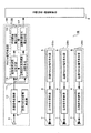
図16は、この発明の実施の形態8に係わる目標測位装置の構成図である。
この発明の実施の形態8に係わる目標測位装置1Hは、実施の形態2に係わる目標測位装置1BとFMCW信号が異なるとともに受信局3Hで目標反射波と直接波とを分離せずに受信することが異なっており、それ以外は同様であるので、同様な部分に同じ符号を付記して説明は省略する。また、送信局2Ha〜2Hc、受信局3Hおよび目標20の位置や相対速度は、図4と同様である。
この実施の形態8に係わる目標測位装置1Hは、受信局3Hが送信局2Ha〜2Hcからの直接波と目標反射波とを分離できずに受信するときの目標測位に適用される。但し、実施の形態8に係わる目標測位装置1Hは、送信局2Ha〜2Hcと受信局3H間の相対速度τ0nが既知のときに適用することができる。
FIG. 16 is a block diagram of a target positioning apparatus according to
The target positioning apparatus 1H according to the eighth embodiment of the present invention is different from the target positioning apparatus 1B according to the second embodiment in the FMCW signal and receives the target reflected wave and the direct wave at the receiving
The target positioning apparatus 1H according to the eighth embodiment is applied to target positioning when the receiving
送信FMCW信号発生器5Hは、図15(a)に示すように、掃引傾斜μ1、掃引傾斜μ2=−μ1、掃引傾斜零の3つの掃引時間TCが連続する周波数パターンの送信FMCW信号を発生する。
受信FMCW信号発生器9Hは、図15(b)に示すように、送信FMCW信号を時刻ずれδtnだけシフトした周波数パターンの受信FMCW信号を発生し、受信FMCW信号に基づいてローカル信号を生成し、受信信号変換器10に送信する。
受信信号変換器10は、受信した電波の信号をローカル信号でミキシングし、ローパスフィルターにより周波数の和信号を除去し、ビート信号を求める。
周波数分析手段19は、ビート信号をフーリエ変換し、出力がピークになる2つのビート周波数を検出する。この2つのビート周波数は、式(36)と式(37)で表すことができる。しかし、このビート周波数のどちらが直接波または目標反射波に係わるものであるか区別することができない。
Transmitting
As shown in FIG. 15B, the reception FMCW signal generator 9H generates a reception FMCW signal having a frequency pattern obtained by shifting the transmission FMCW signal by a time shift δt n and generates a local signal based on the reception FMCW signal. , And transmitted to the received
The
The frequency analyzing means 19 performs Fourier transform on the beat signal and detects two beat frequencies at which the output reaches a peak. These two beat frequencies can be expressed by Expression (36) and Expression (37). However, it cannot be distinguished which of the beat frequencies relates to the direct wave or the target reflected wave.
そこで、距離和速度和推定手段17Hは、式(38)、式(39)のようにビート周波数の差の絶対値を求めることにより、送信局2Ha〜2Hcと目標20の間の伝搬時間τnと目標20と受信局3Hの間の伝搬時間τ0との和(τ0+τn)と、送信局2Ha〜2Hcと目標20との相対速度vnと目標20と受信局3Hとの相対速度v0との和(v0+vn)を求めることができる。なお、この運用形態では送信局2Ha〜2Hcと受信局3H間の相対速度τ0nが既知であり、送信局2Ha〜2Hcと受信局3Hの位置も既知である。
Therefore, the distance sum speed sum estimating means 17H obtains the absolute value of the difference between the beat frequencies as shown in the equations (38) and (39), so that the propagation time τ n between the transmitting stations 2Ha to 2Hc and the
式(38)、式(39)の観測値が得られることで、例えば、In−phaseチャネル(実数のビート信号)のみを計測可能なモノスタティックレーダにおいて、文献(三本著、「同相信号だけを検波するFMCWレーダの目標距離・速度計測方法」、電子情報通信学会、論文誌B、Vol.J82−B、No.12、p.2355−2363、1999年12月)に記載の距離と相対速度のアンビギュイティ(1つの目標時)を取り除く手法により距離和ξn=c(τ0+τn)と相対速度和Vn(ハット)を求めることができる。
そして、実施の形態1と同様に、距離和ξn=c(τ0+τn)と相対速度和Vn(ハット)から目標20の位置と相対速度を推定できる。
By obtaining the observation values of Equation (38) and Equation (39), for example, in a monostatic radar capable of measuring only an In-phase channel (real beat signal), the literature (Three books, “In-phase signal”). FMCW radar target distance / velocity measurement method that detects only the frequency ”, the Institute of Electronics, Information and Communication Engineers, Journal B, Vol. J82-B, No. 12, p. 2355-2363, December 1999) The distance sum ξ n = c (τ 0 + τ n ) and the relative velocity sum V n (hat) can be obtained by a method of removing the relative velocity ambiguity (at one target).
As in the first embodiment, the position and relative speed of the
このような目標測位装置1Hは、一部に周波数掃引が行われないパターンをFMCW信号として採用しているので、ビート信号の差の絶対値から距離和と相対速度和を求めることができ、直接波と目標反射波の受信が分離できないときにも目標の位置と相対速度を推定することができる。 Since the target positioning device 1H employs a pattern in which frequency sweep is not performed in part as the FMCW signal, the distance sum and the relative speed sum can be obtained from the absolute value of the difference between the beat signals. Even when the reception of the wave and the target reflected wave cannot be separated, the target position and relative velocity can be estimated.
なお、実施の形態1乃至8における距離和速度和推定手段を受信局で角度計測を行うことが可能とした場合の目標位置推定法と組み合わせることもできる。 It should be noted that the distance sum speed sum estimation means in Embodiments 1 to 8 can be combined with the target position estimation method in the case where angle measurement can be performed at the receiving station.
1 目標測位装置、2 送信局、3 受信局、4 目標位置・速度推定器、5 送信FMCW信号発生器、6 送信信号変換器、7 送信アンテナ、8 受信アンテナ、9 受信FMCW信号発生器、10 受信信号変換器、11 FMCW信号処理器、13、19 周波数分析手段、14 目標反射波周波数分析手段、15 直接波周波数分析手段、16 時刻誤差推定手段、17 距離和速度和推定手段、18 ケーブル、20 目標。 1 target positioning device, 2 transmitting station, 3 receiving station, 4 target position / speed estimator, 5 transmitting FMCW signal generator, 6 transmitting signal converter, 7 transmitting antenna, 8 receiving antenna, 9 receiving FMCW signal generator, 10 Received signal converter, 11 FMCW signal processor, 13, 19 Frequency analysis means, 14 Target reflected wave frequency analysis means, 15 Direct wave frequency analysis means, 16 Time error estimation means, 17 Distance sum speed sum estimation means, 18 Cable, 20 Goal.
Claims (9)
上記送信局は、
送信FMCW信号を発生する送信FMCW信号発生器と、
電波を上記送信FMCW信号により変調する送信信号変換器と、
を備え、
上記受信局は、
上記FMCW信号と同様な掃引傾斜および掃引時間のローカル信号を発生する受信FMCW信号発生器と、
上記送信局から受信される電波と上記ローカル信号とをミキシングしてビート信号を求める受信信号変換器と、
上記ビート信号の出力が最大になるビート周波数と時刻誤差を算出する周波数分析手段と、
上記ビート周波数と上記時刻誤差とに基づいて上記送信局と上記受信局との距離和と相対速度和とを推定する距離和速度和推定手段と、
を備え、
上記目標位置・速度推定器は、上記受信局から入力される上記距離和と上記時刻誤差とに基づいて上記目標の3次元位置座標を推定し、上記3次元位置座標と上記相対速度和とに基づいて上記目標の3次元相対速度成分を推定することを特徴とする目標測位装置。 Transmitting station that emits radio waves, three or more receiving stations that receive radio waves that arrive directly or after being reflected by the target object, and target position / speed estimation that estimates the target position and speed based on the received radio waves In the target positioning device comprising a device,
The transmitter station
A transmission FMCW signal generator for generating a transmission FMCW signal;
A transmission signal converter for modulating radio waves with the transmission FMCW signal;
With
The receiving station is
A received FMCW signal generator that generates a local signal with a sweep slope and sweep time similar to the FMCW signal;
A reception signal converter for obtaining a beat signal by mixing the radio wave received from the transmission station and the local signal;
Frequency analysis means for calculating the beat frequency and time error at which the output of the beat signal is maximized;
Distance sum speed sum estimation means for estimating a sum of distances and a relative speed sum between the transmitting station and the receiving station based on the beat frequency and the time error;
With
The target position / speed estimator estimates a three-dimensional position coordinate of the target based on the distance sum input from the receiving station and the time error, and calculates the three-dimensional position coordinate and the relative speed sum. A target positioning apparatus characterized by estimating a three-dimensional relative velocity component of the target based on the target.
上記周波数分析手段は、上記直接ビート信号の出力が最大になる直接ビート周波数を算出する直接波周波数分析手段と、上記目標反射ビート信号の出力が最大になる目標反射ビート周波数を算出する目標反射波周波数分析手段と、上記直接ビート周波数に基づいて時刻誤差を推定する時刻誤差推定手段とを備え、
上記距離和速度和推定手段は、上記目標反射ビート周波数と上記時刻誤差とに基づいて上記送信局と上記受信局との距離和と相対速度和とを推定することを特徴とする請求項1に記載する目標測位装置。 The reception signal converter mixes the radio wave received directly from the transmitting station or the radio wave received after being reflected at the target and the local signal to obtain a direct beat signal or target reflected beat signal,
The frequency analyzing means includes a direct wave frequency analyzing means for calculating a direct beat frequency at which the output of the direct beat signal is maximized, and a target reflected wave for calculating a target reflected beat frequency at which the output of the target reflected beat signal is maximized. A frequency analysis means, and a time error estimation means for estimating a time error based on the direct beat frequency,
The distance sum speed sum estimating means estimates the distance sum and relative speed sum between the transmitting station and the receiving station based on the target reflection beat frequency and the time error. Target positioning device to be described.
上記周波数分析手段は、上記目標反射ビート信号の出力が最大になる目標反射ビート周波数を算出する目標反射波周波数分析手段を備え、
上記距離和速度和推定手段は、上記目標反射波周波数分析手段で算出される目標ビート周波数に基づいて上記送信局と上記受信局との時刻誤差を含む距離和と相対速度和とを推定し、
上記目標位置・速度推定器は、上記受信局から入力される上記時刻誤差を含む距離和から時刻誤差を消去することにより上記目標の3次元位置座標を推定し、上記3次元位置座標と上記相対速度和とに基づいて上記目標の3次元相対速度を推定することを特徴とすることを特徴とする請求項1に記載する目標測位装置。 A reception FMCW signal synchronized with the reception FMCW signal supplied to the reception signal converters of the other reception stations is supplied to the reception signal converter of each of the reception stations, and is received after being reflected by the target. To obtain the target reflection beat signal by mixing the radio signal and the local signal
The frequency analyzing means includes target reflected wave frequency analyzing means for calculating a target reflected beat frequency at which the output of the target reflected beat signal is maximized,
The distance sum speed sum estimating means estimates a distance sum and a relative speed sum including a time error between the transmitting station and the receiving station based on the target beat frequency calculated by the target reflected wave frequency analyzing means,
The target position / speed estimator estimates the three-dimensional position coordinates of the target by erasing the time error from the distance sum including the time error input from the receiving station, and the three-dimensional position coordinate and the relative position 2. The target positioning apparatus according to claim 1, wherein a three-dimensional relative speed of the target is estimated based on a speed sum.
上記周波数分析手段は、上記直接ビート信号の出力が最大になる直接ビート周波数を算出する直接波周波数分析手段を備え、
上記距離和速度和推定手段は、上記直接波周波数分析手段で算出される直接ビート周波数に基づいて上記送信局と上記受信局との時刻誤差を含む距離和と相対速度和とを推定し、
上記目標位置・速度推定器は、上記受信局から入力される上記時刻誤差を含む距離和から時刻誤差を消去することにより上記送信局の3次元位置座標を推定し、上記3次元位置座標と上記相対速度和とに基づいて上記送信局の3次元相対速度を推定することを特徴とすることを特徴とする請求項1に記載する目標測位装置。 A reception FMCW signal synchronized with the reception FMCW signal supplied to the reception signal converter of the other reception station is supplied to the reception signal converter of each of the reception stations, and is received directly from the transmission station. The beat signal is obtained directly by mixing the radio wave and the local signal,
The frequency analysis means includes direct wave frequency analysis means for calculating a direct beat frequency at which the output of the direct beat signal is maximized,
The distance sum speed sum estimating means estimates a distance sum and a relative speed sum including a time error between the transmitting station and the receiving station based on the direct beat frequency calculated by the direct wave frequency analyzing means,
The target position / speed estimator estimates the three-dimensional position coordinates of the transmitting station by erasing the time error from the distance sum including the time error input from the receiving station, and the three-dimensional position coordinates and the 2. The target positioning device according to claim 1, wherein a three-dimensional relative speed of the transmitting station is estimated based on a relative speed sum.
上記送信局は、
送信FMCW信号を発生する送信FMCW信号発生器と、
電波を上記送信FMCW信号により変調する送信信号変換器と、
を備え、
上記受信局は、
上記FMCW信号と同様な掃引傾斜および掃引時間のローカル信号を発生する受信FMCW信号発生器と、
上記送信局から受信される電波と上記ローカル信号とをミキシングしてビート信号を求める受信信号変換器と、
上記ビート信号の出力が最大になるビート周波数と時刻誤差を算出する周波数分析手段と、
上記ビート周波数と上記時刻誤差とに基づいて上記送信局と上記受信局との距離和と相対速度和とを推定する距離和速度和推定手段と、
を備え、
上記目標位置・速度推定器は、上記受信局から入力される上記距離和と上記時刻誤差とに基づいて上記目標の3次元位置座標を推定し、上記3次元位置座標と上記相対速度和とに基づいて上記目標の3次元相対速度成分を推定することを特徴とする目標測位装置。 Three or more transmitting stations that radiate radio waves, a receiving station that receives radio waves that arrive directly or after being reflected by the target, and a target position / speed that estimates the target position coordinates and relative speed based on the received radio waves In a target positioning device comprising an estimator,
The transmitter station
A transmission FMCW signal generator for generating a transmission FMCW signal;
A transmission signal converter for modulating radio waves with the transmission FMCW signal;
With
The receiving station is
A received FMCW signal generator that generates a local signal with a sweep slope and sweep time similar to the FMCW signal;
A reception signal converter for obtaining a beat signal by mixing the radio wave received from the transmitting station and the local signal;
Frequency analysis means for calculating the beat frequency and time error at which the output of the beat signal is maximized;
Distance sum speed sum estimating means for estimating a sum of distances and a relative speed sum between the transmitting station and the receiving station based on the beat frequency and the time error;
With
The target position / speed estimator estimates a three-dimensional position coordinate of the target based on the distance sum input from the receiving station and the time error, and calculates the three-dimensional position coordinate and the relative speed sum. A target positioning apparatus characterized by estimating a three-dimensional relative velocity component of the target based on the target.
上記周波数分析手段は、上記直接ビート信号の出力が最大になる直接ビート周波数を算出する直接波周波数分析手段と、上記目標反射ビート信号の出力が最大になる目標反射ビート周波数を算出する目標反射波周波数分析手段と、上記直接ビート周波数に基づいて時刻誤差を推定する時刻誤差推定手段とを備え、
上記距離和速度和推定手段は、上記目標反射ビート周波数と上記時刻誤差とに基づいて上記送信局と上記受信局との距離和と相対速度和とを推定することを特徴とする請求項5に記載する目標測位装置。 The reception signal converter obtains a direct beat signal or a target reflection beat signal by mixing a radio wave directly received from each transmitting station or a radio wave received after being reflected by a target and the local signal,
The frequency analyzing means includes a direct wave frequency analyzing means for calculating a direct beat frequency at which the output of the direct beat signal is maximized, and a target reflected wave for calculating a target reflected beat frequency at which the output of the target reflected beat signal is maximized. A frequency analysis means, and a time error estimation means for estimating a time error based on the direct beat frequency,
6. The distance sum speed sum estimating means estimates a distance sum and a relative speed sum between the transmitting station and the receiving station based on the target reflection beat frequency and the time error. Target positioning device to be described.
上記受信信号変換器は、上記目標で反射してから受信される電波と上記ローカル信号とをミキシングして目標反射ビート信号を求め、
上記周波数分析手段は、上記目標反射ビート信号の出力が最大になる目標反射ビート周波数を算出する目標反射波周波数分析手段を備え、
上記距離和速度和推定手段は、上記目標反射波周波数分析手段で算出される目標ビート周波数に基づいて上記送信局と上記受信局との時刻誤差を含む距離和と相対速度和とを推定し、
上記目標位置・速度推定器は、上記受信局から入力される上記時刻誤差を含む距離和から時刻誤差を消去することにより上記目標の3次元位置座標を推定し、上記3次元位置座標と上記相対速度和とに基づいて上記目標の3次元相対速度を推定することを特徴とすることを特徴とする請求項5に記載する目標測位装置。 A transmission FMCW signal synchronized with the transmission FMCW signal supplied to the transmission signal converter of the other transmission station is supplied to the transmission signal converter of each of the transmission stations,
The reception signal converter mixes a radio wave received after being reflected by the target and the local signal to obtain a target reflected beat signal,
The frequency analyzing means includes target reflected wave frequency analyzing means for calculating a target reflected beat frequency at which the output of the target reflected beat signal is maximized,
The distance sum speed sum estimating means estimates a distance sum and a relative speed sum including a time error between the transmitting station and the receiving station based on the target beat frequency calculated by the target reflected wave frequency analyzing means,
The target position / speed estimator estimates the three-dimensional position coordinates of the target by erasing the time error from the distance sum including the time error input from the receiving station, and the three-dimensional position coordinate and the relative position 6. The target positioning apparatus according to claim 5, wherein a three-dimensional relative speed of the target is estimated based on a speed sum.
上記受信信号変換器は、各上記送信局から直接に受信される電波と上記ローカル信号とをミキシングして直接ビート信号を求め、
上記周波数分析手段は、上記直接ビート信号の出力が最大になる直接ビート周波数を算出する直接波周波数分析手段を備え、
上記距離和速度和推定手段は、上記直接波周波数分析手段で算出される直接ビート周波数に基づいて上記送信局と上記受信局との時刻誤差を含む距離和と相対速度和とを推定し、
上記目標位置・速度推定器は、上記受信局から入力される上記時刻誤差を含む距離和から時刻誤差を消去することにより上記受信局の3次元位置座標を推定し、上記3次元位置座標と上記相対速度和とに基づいて上記受信局の3次元相対速度を推定することを特徴とすることを特徴とする請求項5に記載する目標測位装置。 A transmission FMCW signal synchronized with the transmission FMCW signal supplied to the transmission signal converter of the other transmission station is supplied to the transmission signal converter of each of the transmission stations,
The reception signal converter obtains a beat signal directly by mixing a radio wave directly received from each transmitting station and the local signal,
The frequency analysis means includes direct wave frequency analysis means for calculating a direct beat frequency at which the output of the direct beat signal is maximized,
The distance sum speed sum estimating means estimates a distance sum and a relative speed sum including a time error between the transmitting station and the receiving station based on the direct beat frequency calculated by the direct wave frequency analyzing means,
The target position / speed estimator estimates a three-dimensional position coordinate of the receiving station by erasing the time error from a distance sum including the time error input from the receiving station, and the three-dimensional position coordinate and the 6. The target positioning apparatus according to claim 5, wherein a three-dimensional relative speed of the receiving station is estimated based on a relative speed sum.
上記送信局と上記受信局との間の距離が既知であり、
上記周波数分析手段は、上記ビート信号から2つのビート周波数を算出し、
上記距離和速度和推定手段は、2つの上記ビート周波数の差の絶対値に基づいて上記送信局と上記受信局との距離和と相対速度和とを推定することを特徴とする請求項1または5に記載する目標測位装置。 The transmission FMCW signal and the reception FMCW signal include a time during which the frequency is kept constant,
The distance between the transmitting station and the receiving station is known;
The frequency analysis means calculates two beat frequencies from the beat signal,
The distance sum speed sum estimation means estimates a distance sum and a relative speed sum between the transmitting station and the receiving station based on an absolute value of a difference between two beat frequencies. 5. The target positioning device described in 5.
Priority Applications (1)
| Application Number | Priority Date | Filing Date | Title |
|---|---|---|---|
| JP2006008801A JP2007192575A (en) | 2006-01-17 | 2006-01-17 | Target positioning device |
Applications Claiming Priority (1)
| Application Number | Priority Date | Filing Date | Title |
|---|---|---|---|
| JP2006008801A JP2007192575A (en) | 2006-01-17 | 2006-01-17 | Target positioning device |
Publications (1)
| Publication Number | Publication Date |
|---|---|
| JP2007192575A true JP2007192575A (en) | 2007-08-02 |
Family
ID=38448405
Family Applications (1)
| Application Number | Title | Priority Date | Filing Date |
|---|---|---|---|
| JP2006008801A Pending JP2007192575A (en) | 2006-01-17 | 2006-01-17 | Target positioning device |
Country Status (1)
| Country | Link |
|---|---|
| JP (1) | JP2007192575A (en) |
Cited By (11)
| Publication number | Priority date | Publication date | Assignee | Title |
|---|---|---|---|---|
| JP2012068224A (en) * | 2010-08-23 | 2012-04-05 | Toshiba Corp | Mimo radar system, transmitting unit, receiving unit, and mimo radar signal processing method |
| JP2014517253A (en) * | 2011-02-25 | 2014-07-17 | ネーデルランツ オルガニサティー フォール トゥーゲパストナトゥールヴェテンシャッペリーク オンデルズーク テーエンオー | FMCW radar system with multiple transmitters and beat frequency multiplex |
| JP2016161409A (en) * | 2015-03-02 | 2016-09-05 | 株式会社東芝 | Radar system and radar signal processing method thereof |
| JP2018084432A (en) * | 2016-11-21 | 2018-05-31 | 株式会社東芝 | Radar system and radar signal processing method thereof |
| WO2019234900A1 (en) * | 2018-06-07 | 2019-12-12 | 三菱電機株式会社 | Radar device |
| JP6797339B1 (en) * | 2020-03-13 | 2020-12-09 | 三菱電機株式会社 | Radar device |
| JP2021523380A (en) * | 2018-05-17 | 2021-09-02 | ロベルト・ボッシュ・ゲゼルシャフト・ミト・ベシュレンクテル・ハフツングRobert Bosch Gmbh | Radar sensor system and manufacturing method of radar sensor system |
| JP2022134285A (en) * | 2021-03-03 | 2022-09-15 | 株式会社ソシオネクスト | Information transmission method, information processing method and mobile receiving terminal |
| US11662452B2 (en) | 2019-11-19 | 2023-05-30 | Samsung Electronics Co., Ltd. | Method and apparatus with measuring of three-dimensional position using radar sensor |
| CN116614876A (en) * | 2022-02-08 | 2023-08-18 | 维沃移动通信有限公司 | Positioning method, positioning device, user equipment and storage medium |
| WO2023160711A1 (en) * | 2022-02-28 | 2023-08-31 | 维沃移动通信有限公司 | Group positioning methods and apparatus, and communication device |
-
2006
- 2006-01-17 JP JP2006008801A patent/JP2007192575A/en active Pending
Cited By (17)
| Publication number | Priority date | Publication date | Assignee | Title |
|---|---|---|---|---|
| JP2012068224A (en) * | 2010-08-23 | 2012-04-05 | Toshiba Corp | Mimo radar system, transmitting unit, receiving unit, and mimo radar signal processing method |
| JP2014517253A (en) * | 2011-02-25 | 2014-07-17 | ネーデルランツ オルガニサティー フォール トゥーゲパストナトゥールヴェテンシャッペリーク オンデルズーク テーエンオー | FMCW radar system with multiple transmitters and beat frequency multiplex |
| JP2016161409A (en) * | 2015-03-02 | 2016-09-05 | 株式会社東芝 | Radar system and radar signal processing method thereof |
| JP2018084432A (en) * | 2016-11-21 | 2018-05-31 | 株式会社東芝 | Radar system and radar signal processing method thereof |
| JP2021523380A (en) * | 2018-05-17 | 2021-09-02 | ロベルト・ボッシュ・ゲゼルシャフト・ミト・ベシュレンクテル・ハフツングRobert Bosch Gmbh | Radar sensor system and manufacturing method of radar sensor system |
| WO2019234900A1 (en) * | 2018-06-07 | 2019-12-12 | 三菱電機株式会社 | Radar device |
| CN112204421A (en) * | 2018-06-07 | 2021-01-08 | 三菱电机株式会社 | Radar device |
| JPWO2019234900A1 (en) * | 2018-06-07 | 2020-09-17 | 三菱電機株式会社 | Radar device |
| CN112204421B (en) * | 2018-06-07 | 2023-06-16 | 三菱电机株式会社 | Radar apparatus, control circuit, and program storage medium |
| US11662452B2 (en) | 2019-11-19 | 2023-05-30 | Samsung Electronics Co., Ltd. | Method and apparatus with measuring of three-dimensional position using radar sensor |
| US12050258B2 (en) | 2019-11-19 | 2024-07-30 | Samsung Electronics Co., Ltd. | Method and apparatus with measuring of three-dimensional position using radar sensor |
| JP6797339B1 (en) * | 2020-03-13 | 2020-12-09 | 三菱電機株式会社 | Radar device |
| JP2022134285A (en) * | 2021-03-03 | 2022-09-15 | 株式会社ソシオネクスト | Information transmission method, information processing method and mobile receiving terminal |
| JP7619090B2 (en) | 2021-03-03 | 2025-01-22 | 株式会社ソシオネクスト | Information transmission method and information processing method |
| CN116614876A (en) * | 2022-02-08 | 2023-08-18 | 维沃移动通信有限公司 | Positioning method, positioning device, user equipment and storage medium |
| WO2023160711A1 (en) * | 2022-02-28 | 2023-08-31 | 维沃移动通信有限公司 | Group positioning methods and apparatus, and communication device |
| CN116709171A (en) * | 2022-02-28 | 2023-09-05 | 维沃移动通信有限公司 | Group positioning method, device and communication equipment |
Similar Documents
| Publication | Publication Date | Title |
|---|---|---|
| JP7357585B2 (en) | Radar system method, radar system and radar system device | |
| JP5197138B2 (en) | Multi static radar device | |
| US6703967B1 (en) | Distance measuring device | |
| CN112470023B (en) | Positioning method and positioning system for locating at least one object by using wave-based signals | |
| US8354955B2 (en) | Observation signal processing apparatus | |
| EP2525238B1 (en) | Velocity/distance detection system, velocity/distance detection apparatus, and velocity/distance detection method | |
| EP4258019A1 (en) | Phase noise reduction for symmetric bistatic radar | |
| JP2020509386A (en) | Method and apparatus for capturing surroundings | |
| JP2006177907A (en) | Interferometric radar | |
| KR20080039473A (en) | Distance measuring device and distance measuring method | |
| US12210118B2 (en) | Radar target simulator with continuous distance emulation and corresponding simulation method | |
| JP7125785B2 (en) | Speed measuring device, speed measuring program, recording medium and speed measuring method | |
| CN114002677B (en) | A distributed radar | |
| JP4899937B2 (en) | FMCW synthetic aperture radar, drift angle detection method, program, and storage medium | |
| US12222436B2 (en) | Radar method and radar system | |
| JP2007192575A (en) | Target positioning device | |
| US11125857B2 (en) | Moving object detection system and moving object detection method | |
| JP2013029419A (en) | Positioning device | |
| JP2007509330A (en) | Measuring device for automobile | |
| RU2687057C1 (en) | Method of determining coordinates of a moving object | |
| EP0436302A2 (en) | Integrated altimeter and doppler velocity sensor arrangement | |
| JP3484995B2 (en) | Instantaneous passive distance measuring device | |
| JP2007192573A (en) | Target positioning device | |
| RU2367974C2 (en) | Method for detection of non-radial projection of moving target speed | |
| JP4893883B2 (en) | Radio altitude speed measuring apparatus and altitude speed measuring method using radio wave |