JP2007192089A - Structure for cylinder head and cylinder block - Google Patents
Structure for cylinder head and cylinder block Download PDFInfo
- Publication number
- JP2007192089A JP2007192089A JP2006009937A JP2006009937A JP2007192089A JP 2007192089 A JP2007192089 A JP 2007192089A JP 2006009937 A JP2006009937 A JP 2006009937A JP 2006009937 A JP2006009937 A JP 2006009937A JP 2007192089 A JP2007192089 A JP 2007192089A
- Authority
- JP
- Japan
- Prior art keywords
- cylinder head
- head
- combustion chamber
- cylinder
- component
- Prior art date
- Legal status (The legal status is an assumption and is not a legal conclusion. Google has not performed a legal analysis and makes no representation as to the accuracy of the status listed.)
- Withdrawn
Links
Images


Abstract
Description
本発明は、エンジンのシリンダヘッド又はシリンダブロックを分割して鋳造し、一体化して製造する技術に関するものである。 The present invention relates to a technique for dividing and casting a cylinder head or a cylinder block of an engine, and manufacturing it integrally.
自動車のエンジンには、重量の軽減、及び冷却性能の向上その他の目的で、アルミニウム合金製のシリンダヘッドや、シリンダブロックが広く採用されている。
このうちシリンダヘッドは、その内部に、吸気ポート、排気ポート、燃料を爆発させる燃焼室の一部、及び冷却水を流通させるウォータジャケットを備えており、通常は鋳造によって一体成形されている。
吸気ポート、排気ポート、燃焼室、及びウォータジャケットは、内部に流体を通すために、シリンダヘッドは中空部を形成する複雑な構造となっている。
このため従来からシリンダヘッドは、吸気ポート、排気ポート、ウォータジャケットを成形するための多数の中子を用いて鋳造されていた。
また、シリンダヘッドを一体鋳造する場合、複雑な形状が鋳造可能な低圧鋳造法を用いることが通例であった。
しかし、低圧鋳造法は鋳造速度の制限から鋳造速度を上げることが出来ないので、生産性を向上させるのが難しいという問題がある。
2. Description of the Related Art For automobile engines, cylinder heads and cylinder blocks made of aluminum alloy are widely used for weight reduction, cooling performance improvement and other purposes.
Among them, the cylinder head includes an intake port, an exhaust port, a part of a combustion chamber for exploding fuel, and a water jacket for circulating cooling water, and is usually integrally formed by casting.
The intake port, the exhaust port, the combustion chamber, and the water jacket have a complicated structure in which the cylinder head forms a hollow portion for allowing fluid to pass therethrough.
For this reason, conventionally, a cylinder head has been cast using a large number of cores for forming an intake port, an exhaust port, and a water jacket.
In addition, when the cylinder head is integrally cast, it is usual to use a low pressure casting method capable of casting a complicated shape.
However, the low pressure casting method has a problem that it is difficult to improve the productivity because the casting speed cannot be increased due to the limitation of the casting speed.
鋳造速度を上げることができない理由は、溶湯を供給するための圧縮空気の圧力を、一定値以上高くすることができないためである。
また、シリンダヘッドを低圧鋳造法によって製作するにあたっては、多数の崩壊性の中子を用いて鋳造を行うために、鋳造が終わった後に、崩壊性の中子の除去工程が必要となる。
さらに、鋳造の度に取り出すために崩壊させてしまうため、崩壊性の中子は、製品1つ辺りに1セットの崩壊性の中子を制作する必要がある。崩壊性の中子を形成するのに用いるケイ砂は再利用をしているが、毎回制作を要するためにコストと手間がかかる。
このように、鋳造速度が上げられない点や、中子を複数用いなければならず、鋳造後に中子を崩して取り出さなければならない等の手間がかかる点から、シリンダヘッドの生産コストを下げることが出来なかった。
The reason why the casting speed cannot be increased is that the pressure of the compressed air for supplying the molten metal cannot be increased above a certain value.
Further, when the cylinder head is manufactured by the low pressure casting method, since the casting is performed using a large number of collapsible cores, a step of removing the collapsible cores is required after the casting is finished.
Furthermore, since the collapsible core is collapsed to be taken out every casting, it is necessary to produce one set of collapsible core per product. The silica sand used to form the collapsible core is reused, but it requires cost and labor because it requires production every time.
In this way, the production cost of the cylinder head is reduced from the point that the casting speed cannot be increased and that it is necessary to use a plurality of cores and the cores must be broken and removed after casting. I couldn't.
この点に着目して、崩壊性の中子を用いず、鋳造速度の速いダイカスト鋳造にて製造するシリンダヘッドについて開示しているのが、特許文献1である。
図8は特許文献1の接合構造シリンダヘッドの断面図を示している。
特許文献1のシリンダヘッド10は、上方の冷却水室116を横切り、図8の紙面に対し前後方向に延在する接合面X―X及び吸気ポート11、及び排気ポート12を横切る接合面Y―Yによって分割された上部ヘッド部材110a、中部ヘッド部材110b、及び下部ヘッド部材110cの3つの構成部材に分割されている。
これら3分割された、シリンダヘッドの構成部材は、何れも冷却水室116、122、及び吸気ポート11、及び排気ポート12を形成するための崩壊性の中子を必要としない。したがって、従来の低圧鋳造法よりも著しく生産性が高い、例えばダイカスト機を用いて極めて生産性良く製造することが出来る。
Patent Document 1 discloses a cylinder head manufactured by die casting at a high casting speed without using a collapsible core, paying attention to this point.
FIG. 8 shows a cross-sectional view of the bonded structure cylinder head of Patent Document 1.
The
None of these three-divided components of the cylinder head require a collapsible core for forming the
しかし、特許文献1において、図8のように接合面Y―Yを設ける場合、接合面Y―Yは吸気ポート11及び排気ポート12の中心部分を分割し、燃焼室15を通過している。
燃焼室15ではエンジン稼働時に燃料を爆発させて動力を取り出しているので、燃料の燃焼時には高温高圧のガスが瞬時に発生し、そのガスの圧力に燃焼室15は直接さらされる。
このように高温のガスにさらされることで、燃焼室15の壁面を構成する材料は膨張収縮を繰り返すことになり、さらに瞬間的に高圧ガスが発生するために衝撃力をも受けることになる。
したがって、特許文献1のように燃焼室15に接合面を設けた場合、燃料燃焼時の熱負荷による膨張収縮や、連続的に発生する衝撃力にさらされ、接合部に亀裂が入ってしまうなどの問題が考えられる。
However, in Patent Document 1, when the joint surface YY is provided as shown in FIG. 8, the joint surface YY divides the central portion of the
In the
By being exposed to the high-temperature gas in this way, the material constituting the wall surface of the
Therefore, when the joint surface is provided in the
そこで、本出願人は、このような点も配慮したシリンダヘッドを分割鋳造する技術について特許文献2に開示している。
図9は特許文献2のシリンダヘッドの断面図を示している。
特許文献2のシリンダヘッド10は、分割型シリンダヘッドで、接合面Y―Yで分割されるアッパヘッド21とロアヘッド22からなる。アッパヘッド21は、吸気ポート11、排気ポート12、ウォータジャケット13、図示しない点火プラグ穴を有し、動弁系などの機能部品を有する。
ロアヘッド22は、アッパヘッド21とは別ピースであり、アッパヘッド21とシリンダブロック(図示略)との間に介在され、燃焼室15の上壁を形成する。
Therefore, the present applicant discloses in Japanese Patent Application Laid-Open No. H11-228707 a technique for dividing and casting a cylinder head in consideration of such points.
FIG. 9 shows a cross-sectional view of the cylinder head of Patent Document 2.
The
The
この様な構成になっているので、例えばアッパヘッド21を鋳造で、ロアヘッド22を鍛造で作ることにより、燃焼圧を受けるロアヘッド22の強度をアップさせることができ、燃焼圧を直接受けないアッパヘッド21は安価な材料にすることも可能である。
さらに、アッパヘッド21とロアヘッド22が分割されることで、熱負荷のかかる燃焼室15や点火プラグ雌ネジ部14の付近の肉厚を任意に薄くすることが可能で、鋳造や鍛造では成型することが出来ない形状に機械加工することも可能となる。これによって冷却性能の向上を図ることも可能となる。
Furthermore, by dividing the
しかしながら、特許文献2に開示される方法では以下の問題が考えられる。
(1)分割面を跨いで配設された部品取り付け穴に、亀裂が生じる恐れがある。
アッパヘッド21とロアヘッド22を接合するには、母材よりも融点の低い金属が接合剤として用いられる。その結果、接合部は他の部分よりも材料の強度が低くなってしまう。
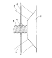
図10に、アッパヘッド21とロアヘッド22を接合した場合の、燃焼室15付近の拡大図を示す。この図10は特許文献2の問題を簡単に説明するために、接合面Y―Yを1枚の平面で切断した場合の部分拡大図としている。
このように、アルミニウム合金製のアッパヘッド21とロアヘッド22が、例えば亜鉛系の接合剤を用い、接合面Y―Yで接合されれば、亜鉛系の接合層25が出来上がる。この接合層25は、低融点金属が主成分となるので、母財部分であるアッパヘッド21及びロアヘッド22と比べて強度が低くなる。
However, the method disclosed in Patent Document 2 has the following problems.
(1) There is a risk of cracks occurring in the component mounting holes arranged across the split surfaces.
In order to join the
FIG. 10 shows an enlarged view of the vicinity of the
As described above, when the
一方、エンジン稼働時には、シリンダヘッド10の有する燃焼室15で連続的に燃料を爆発させて動力を取り出している。この時に発生する燃焼ガスは高温高圧となり、爆発の衝撃や熱応力など材料に大きな負荷がかかる。
この負荷によって、図10に示す点火プラグ雌ネジ部14など、接合層25を跨いで部品が取り付けられる部分に接合層25とネジの谷部が重なるような加工や、接合層25と段差が重なるような加工や、接合層25と凹部が重なるような加工が必要な場合、その部分に応力が集中して亀裂が発生する可能性があり問題である。
On the other hand, when the engine is in operation, the fuel is continuously exploded in the
Due to this load, processing such that the joining
(2)接合層とネジの谷部が一致する場所では亀裂が生じやすい。
図11には、図10のC部分拡大図を示す。
上述した(1)の問題は、特にネジの谷部14aと接合層25が一致する場所で、特に問題となる。
燃焼室15に設けられる点火プラグ雌ネジ部14は、図示しない点火プラグを組み付けるために設けられている。
ネジ山は被加工物に対して螺旋状に設けられる。したがって、接合層25を跨いで点火プラグ雌ネジ部14の加工を行うと、必ずこのように接合層25とネジの谷部14aが一致する場所ができる。
そして、接合層25の剛性は他と比べて低いので、エンジン稼働中に発生する熱応力や、爆発による振動によって、このような応力が集中したネジの谷部14aには亀裂26が入りやすくなり問題である。
(2) Cracks are likely to occur at locations where the bonding layer and screw valleys coincide.
FIG. 11 is an enlarged view of part C of FIG.
The problem (1) described above is particularly problematic in the place where the
The spark plug
The screw thread is provided spirally with respect to the workpiece. Therefore, when the spark plug
Since the rigidity of the
(3)亀裂の引き起こす派生的な問題について。
上述した(1)や(2)のように、接合層25にネジの谷部14aのような凹部が重なると亀裂26が発生しやすい。
そして発生した亀裂26は、エンジン稼働時に発生する熱応力や振動の影響から徐々に成長する。
点火プラグ雌ネジ部14の隣は、シリンダヘッド10の壁を挟んで冷却水を流しているウォータジャケット13が存在するので、亀裂26が成長し、ウォータジャケット13まで貫通すると、点火プラグ雌ネジ部14を通過して燃焼室15に冷却水が入り込む結果となり、エンジンの燃費低下や点火プラグの失火、最悪エンジンブローに繋がりかねない。
つまり亀裂26の発生は、直接エンジンの性能低下に結びついてしまう。
(3) Derivative problems caused by cracks.
As described above in (1) and (2), when the concave portion such as the
The generated
Next to the spark plug
That is, the generation of the
このように、特許文献2においては、分割し一体化したシリンダヘッドやシリンダブロックの第1構成部材と第2構成部材を跨いて配設された部品取り付け穴等の接合部分に亀裂が生じやすいという問題があった。 Thus, in Patent Document 2, it is said that cracks are likely to occur in joint portions such as component mounting holes disposed across the first and second component members of the cylinder head and cylinder block that are divided and integrated. There was a problem.
そこで、本発明ではこのような問題を解決するためになされたものであり、分割し一体化したシリンダヘッドやシリンダブロックの第1構成部材と第2構成部材を跨いて配設された部品取り付け穴等の接合部分に、亀裂が生じないシリンダヘッドやシリンダブロックの構造を提供することを目的とする。 Accordingly, the present invention has been made in order to solve such a problem, and is a component mounting hole arranged across the first and second constituent members of the cylinder head and cylinder block which are divided and integrated. An object of the present invention is to provide a structure of a cylinder head or a cylinder block that does not cause cracks at joint portions such as the above.
前記目的を達成するために、本発明によるシリンダヘッド又はシリンダブロックの構造は以下のような特徴を有する。
(1)各々が分割面を備える第1構成部材と第2構成部材が成形され、前記第1構成部材と前記第2構成部材が前記分割面で接合されたシリンダヘッド又はシリンダブロックの構造において、部品を取り付ける部品取付穴を備えた部品取付部材が、前記第1構成部材に形成される第1保持穴と、前記第2構成部材に形成される第2保持穴に、前記分割面を跨いで挿入して固定されることを特徴とする。
ここでいう「部品」とは、例えば点火プラグやインジェクタ、バルブガイド等、シリンダヘッド取り付けられる部品を指す。
またここでいう「部品取付部材」とは、「部品」を取り付けるためにシリンダヘッドに設けられる別体の部材であり、例えば点火プラグ等を取り付ける「部品取付部材」であれば、その内部に雌ねじ加工が施される。
In order to achieve the above object, the structure of the cylinder head or cylinder block according to the present invention has the following characteristics.
(1) In the structure of a cylinder head or a cylinder block in which a first component member and a second component member each having a dividing surface are molded, and the first component member and the second component member are joined at the dividing surface, A component mounting member having a component mounting hole for mounting a component straddles the divided surface between a first holding hole formed in the first component member and a second holding hole formed in the second component member. It is inserted and fixed.
The “component” here refers to a component to which a cylinder head is attached, such as a spark plug, an injector, and a valve guide.
Further, the “component mounting member” here is a separate member provided in the cylinder head for mounting the “component”. For example, if it is a “component mounting member” for mounting a spark plug or the like, an internal thread is provided therein. Processing is applied.
(2)(1)に記載のシリンダヘッド又はシリンダブロックの構造において、前記部品取付部材の前記部品取付穴に、部品螺合用のネジ溝が形成されることを特徴とする。
(3)(1)又は(2)に記載されるシリンダヘッドの構造において、前記部品取付部材が、エンジンの燃焼室に面して設けられ、前記部品取付部材の外形が、前記燃焼室から遠ざかる方向に縮径していることを特徴とする。
(4)(1)乃至(3)のいずれか1つに記載されるシリンダヘッドの構造において、前記部品取付部材が、前記燃焼室のシリンダヘッド側の壁面を構成し、吸気ポート及び排気ポートを備えることを特徴とする。
(2) In the structure of the cylinder head or cylinder block according to (1), a thread groove for threading a part is formed in the part mounting hole of the part mounting member.
(3) In the structure of the cylinder head described in (1) or (2), the component mounting member is provided facing the combustion chamber of the engine, and the outer shape of the component mounting member is moved away from the combustion chamber. The diameter is reduced in the direction.
(4) In the structure of the cylinder head described in any one of (1) to (3), the component mounting member constitutes a wall surface on the cylinder head side of the combustion chamber, and an intake port and an exhaust port are provided. It is characterized by providing.
このような特徴を有する本発明によるシリンダヘッド又はシリンダブロックの構造により、以下のような作用、効果が得られる。
接合された第1構成部材と第2構成部材に、部品取付穴を備えた部品取付部材を、分割面を跨いで設けることで、例えば、点火プラグを取り付ける為のネジ加工した際に、ネジの谷部が分割面と一致し、亀裂が入ることを防止することが可能である。
これは、例えば点火プラグをシリンダヘッドに取り付ける場合、第1構成部材と第2構成部材が接合され、第1保持穴と第2保持穴が連通して、その部分に部品取付部材を、分割面を跨ぐようにして圧入又は接合し、シリンダヘッドに取り付けられた部品取付部材にネジ溝の形成を行う。
この際に、部品取付部材が、第1構成部材に設けられる第1保持穴と第2構成部材に形成される第2保持穴に、分割面を跨いで設けられるので、その後で形成されるネジ溝のネジの谷部が分割面と一致するようなことはなくなる。
The following operations and effects can be obtained by the structure of the cylinder head or cylinder block according to the present invention having such characteristics.
For example, when a screw for attaching a spark plug is machined by providing a component mounting member having a component mounting hole on the joined first component and second component so as to straddle the split surface, It is possible to prevent the valley portion from being coincident with the dividing surface and cracking.
For example, when the spark plug is attached to the cylinder head, the first component member and the second component member are joined, the first holding hole and the second holding hole communicate with each other, and the component mounting member is divided into the part. The groove is formed in the component mounting member attached to the cylinder head by press-fitting or joining so as to straddle.
At this time, the component mounting member is provided in the first holding hole provided in the first component member and the second holding hole formed in the second component member so as to straddle the divided surface. The trough of the screw in the groove will not coincide with the dividing surface.
ネジの谷部と、分割面にできる接合層とが一致する場所では、応力集中が起こりやすい。そのような場所は、疲労破壊の起点となり、分割面に亀裂が入るなどの原因となることが考えられる。
このような場合にも、部品取付穴を備えた別体である部品取付部材を、圧入や接合などの方法で取り付け、この部品取付部材にネジを切ることで、シリンダヘッド又はシリンダブロックの有する部品取付部に直接雌ねじを切る必要がなくなる。
これにより、分割面とネジ溝の谷部が一致した場合に起こる、応力集中や、それによる亀裂の発生や、疲労破壊の原因を取り除くことができる。
また、このような応力集中は、ネジ溝を設けない場合でも、凹部や段差が接合面と一致する場合にも起こると考えられるが、そのような問題も部品取付部材を用いることで解決しうる。
Stress concentration is likely to occur at locations where the thread valleys coincide with the joining layer formed on the split surface. Such a place is considered to be a starting point for fatigue failure and cause cracks in the split surface.
Even in such a case, a component mounting member, which is a separate body provided with a component mounting hole, is attached by a method such as press-fitting or joining, and a screw is cut into this component mounting member, so that the component that the cylinder head or cylinder block has There is no need to cut the female thread directly on the mounting part.
Thereby, it is possible to remove the stress concentration, the occurrence of cracks due to the stress, and the cause of fatigue failure, which occur when the divided surface and the valley of the screw groove coincide.
In addition, such stress concentration is considered to occur even when the screw groove is not provided, but also when the concave portion or the step is coincident with the joint surface, but such a problem can be solved by using the component mounting member. .
また、部品取付部材が、エンジンの燃焼室に面して設けられ、前記部品取付部材の外形が、前記燃焼室から遠ざかる方向に縮径しているので、シリンダヘッドに備えられるエンジンの燃焼室において、エンジン稼働時に起こる燃料の燃焼、爆発による圧力の影響を受けて、部品取付部材が上側に抜けたり、脱落したりすることがない。また、このように構成することで、部品取付部材自体が全体で応力を受けるので、強度上有利となる。 In addition, since the component mounting member is provided facing the combustion chamber of the engine, and the outer shape of the component mounting member is reduced in a direction away from the combustion chamber, the engine mounting chamber is provided with a cylinder head. The component mounting member does not fall upward or drop off due to the influence of the pressure of fuel combustion or explosion that occurs during engine operation. Also, with this configuration, the component mounting member itself receives stress as a whole, which is advantageous in terms of strength.
また、部品取付部材が、燃焼室のシリンダヘッド側の壁面を構成し、吸気ポート及び排気ポートを備えるので、エンジンの燃焼室を別部材で製造することが可能であり、シリンダブロックはアルミ合金で作られることが多いが、エンジンの燃焼室だけは鉄系の材料を用いて剛性を上げることが可能である。
このようにすることで、強度が必要な部材を集中することができるために、性能を向上させた上で、コストダウンにも寄与することが可能となる。
Further, since the component mounting member constitutes the wall surface on the cylinder head side of the combustion chamber and includes the intake port and the exhaust port, the combustion chamber of the engine can be manufactured as a separate member, and the cylinder block is made of an aluminum alloy. Although it is often made, only the combustion chamber of the engine can be increased in rigidity by using an iron-based material.
By doing in this way, since the member which needs intensity | strength can be concentrated, it becomes possible to contribute also to cost reduction while improving performance.
以下、本発明の実施例について図面を用いて説明する。
(第1実施例)
以下、第1実施例の構成について説明する。
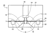
図1は、シリンダヘッド10を接合面Y―Yでアッパヘッド21とロアヘッド22に分割した立体斜視図を示している。
また、図2は、ロアヘッド22の立体斜視図を示している。
第1実施例のシリンダヘッド10は、一般的な車両に用いられる直列4気筒で4バルブのエンジンに組み付けられるものである。
シリンダヘッド10は、側面に吸気ポート11を有しており、図示しないインテークマニホールドが接続される。また、他方の側面には図示しない排気ポート12を有し、図示しないエキゾーストマニホールドに接続される。
シリンダヘッド10の上部には、図示しないシリンダキャップが、下部には図示しないシリンダブロックが組み付けられ、その他様々な補機類が取り付けられ、エンジンとして稼働することとなる。
このようなシリンダヘッド10は、近年ではアルミニウム合金を鋳造して制作されるのが一般的である。鋳鉄に比べて軽量で冷却効率が良く、車の性能の向上に繋がるためである。
また、第1実施例のシリンダヘッド10は、第1構成部材及び第2構成部材に対応する、アッパヘッド21を例えば低圧鋳造法によって鋳造し、ロアヘッド22を例えばダイカスト鋳造法によって鋳造し、アッパヘッド21とロアヘッド22を一体化することで製造される、分割式のシリンダヘッドである。
Embodiments of the present invention will be described below with reference to the drawings.
(First embodiment)
The configuration of the first embodiment will be described below.
FIG. 1 shows a three-dimensional perspective view in which the
FIG. 2 shows a three-dimensional perspective view of the
The
The
A cylinder cap (not shown) is assembled to the upper part of the
In recent years, such a
Further, the
なお、図2に示すロアヘッド22は、接合面Y―Yで分割することで崩壊性の中子が必要となる中空部を無くすことが可能なので、ダイカスト鋳造法を用いて低コストに生産することが可能である。
また、このロアヘッド22は強度が必要な部品となるため、鍛造等の製造方法によって製作したり、ロアヘッド22を鋳鉄のように強度のある材料で製作したりしても良い。
もちろん、アッパヘッド21についても分割することで、崩壊性の中子を廃止することが可能なので、特許文献1に示されているように適宜分割して生産しても良い。
The
Since the
Of course, the collapsible core can be abolished by dividing the
図3には、図2に示したAA断面で、シリンダヘッド10を切断した断面図を示している。
シリンダヘッド10の下部に備えられる燃焼室15には、吸気ポート11及び排気ポート12が接続されている。
接合面Y―Yは、燃焼室15の上部を通過し、シリンダヘッド10を平面で切断しており、ウォータジャケット13も分割する。
アッパヘッド21及びロアヘッド22を接合する際には、接合面Y―Yに亜鉛系のロウ材を用いて接合する。ロウ材については、亜鉛系に限ることなく、被接合剤よりも低融点であり、エンジンとして車に組み込まれたシリンダヘッド10の使用環境下においてシール性と接合強度が確保できれば良い。
このようにしてアッパヘッド21及びロアヘッド22が接合されることで、接合層25ができる。この接合層25の厚みは0.1〜0.2mm程度となる。なお、この接合層25の厚みは、アッパヘッド21及びロアヘッド22の各々の接合面Y―Yを機械加工により、平面度、面粗度等を更に向上させれば、もっと薄くても良い。
FIG. 3 shows a cross-sectional view of the
An
The joint surface YY passes through the upper part of the
When the
By joining the
燃焼室15の上部には、部品取り付け部材に対応するブッシュ20が設けられている。
このブッシュ20は、ブッシュ細径部20aとブッシュ太径部20bからなる段付きの形状をしており、ブッシュ細径部20aが燃焼室15から遠い側に、ブッシュ太径部20bの下面が燃焼室15に面して、シリンダヘッド10に備えられることになる。
また、ブッシュ20は、鉄系かアッパヘッド21及びロアヘッド22よりも強度の高いアルミニウム合金等で作られている。
一方、アッパヘッド21及びロアヘッド22は鋳造等によって制作される際に、ブッシュ20を圧入又は接合するために、アッパヘッド21には第1保持穴21a、ロアヘッド22には第2保持穴22aが形成される。
そして、ブッシュ20は、アッパヘッド21の第1保持穴21a及びロアヘッド22の第2保持穴22aに圧入又は接合されて固定されており、部品取付穴に対応する点火プラグ雌ネジ部14を有している。
ブッシュ20の圧入又は接合については、アッパヘッド21とロアヘッド22を接合する前にロアヘッド22に先に行っても良いし、アッパヘッド21とロアヘッド22を一体化した後に行っても良い。
A
The
The
On the other hand, when the
The
The press-fitting or joining of the
図4に、図3のB部の拡大断面図を示す。
ブッシュ20は、段付きの円筒形状をしており、燃焼室15に面する側の径が大きくなっている。ブッシュ20はシリンダヘッド10に圧入又は接合される。
また、ブッシュ20の長さは、ロアヘッド22の燃焼室15から接合面Y―Yまでの厚みよりも長く、アッパヘッド21とロアヘッド22が組み合わされた状態で、接合面Y―Yを跨ぐ状態となっている。
ブッシュ20は、図示しない点火プラグ23を取り付ける部分である燃焼室15の上部に圧入又は接合して設けられるものであり、その長さは、接合面Y―Yを跨いでいれば、点火プラグ差し込み穴17まで達するものであっても、図4に示すように途中までの長さのものであってもよい。
シリンダヘッド10にブッシュ20を圧入又は接合した後、図示しない点火プラグ23を組み付けるための点火プラグ雌ネジ部14を設ける。
なお、点火プラグ雌ネジ部14は最初から設けられていても良いが、この場合は、ブッシュ20の長さは、点火プラグ23を保持するための点火プラグ雌ネジ部14を設けるのに十分な長さが必要である。
FIG. 4 shows an enlarged cross-sectional view of a portion B in FIG.
The
In addition, the length of the
The
After the
Note that the spark plug
第1実施例は以上のような構成になっているので、以下のような効果作用を示す。
まず、接合層25と点火プラグ雌ネジ部14の一致がなくなる。
図5に、シリンダヘッド10に点火プラグ23が取り付けられた状態のB部詳細断面図を示す。
図示しないシリンダブロックに組み付けられたシリンダヘッド10は、燃焼室15内に燃料を供給した後、圧縮、爆発を行い、燃焼室15内で圧力30を発生する。圧力30は、燃焼室15内で広がろうとする力であり、燃焼室15の内壁に対して押し付ける方向の力が働く。
この際に燃焼室15の一部を構成しているブッシュ20についても、図面上方向に断続的に圧力30を受けることになる。
シリンダヘッド10にブッシュ20を圧入又は接合し、点火プラグ雌ネジ部14の加工をする。この結果、図11で示したように、接合層25にネジの谷部14aが一致するような加工ではなくなる。したがって、接合層25とネジの谷部14aが一致した部分に応力が集中して亀裂26が発生し、破壊に繋がるようなことがなくなる。
Since the first embodiment is configured as described above, the following effects are exhibited.
First, the coincidence between the
FIG. 5 is a detailed cross-sectional view of a B portion in a state where the
The
At this time, the
A
これは、シリンダヘッド10に接合面Y―Yを跨ぐように、すなわち接合層25を跨ぐようにブッシュ20が圧入又は接合されているので、点火プラグ雌ネジ部14の加工を行っても、接合層25の部分に点火プラグ雌ネジ部14が直接行われることはないからである。
仮に、この接合層25部分に亀裂が入り、破壊が進むと、シリンダヘッド10内部に設けられたウォータジャケット13や、吸気ポート11、排気ポート12等が繋がってしまうなどの悪影響が考えられる。
吸気ポート11及び排気ポート12とウォータジャケット13が連通すると、ウォータジャケット13の中を流れる冷却水が、吸気ポート11及び排気ポート12側に漏れ出すこととなり、それによって燃焼室15側にも冷却水が入り込む危険性がある。冷却水は少量入り込んだだけでも水蒸気となって燃焼室15内で燃料に混じり性能低下に繋がるという悪影響がある。冷却水の漏れ量が多ければ、最悪エンジンブローにも繋がりかねない。
したがって、第1実施例のように構成することで、こういった事態を防ぐことが可能となる。
This is because the
If the
When the
Therefore, such a situation can be prevented by configuring as in the first embodiment.
また、シリンダヘッド10に圧入又は接合されているブッシュ20は、このような圧力30を受け、ブッシュ20が燃焼室15から遠ざかる方向で縮径するように段付きになっている、つまり力がかかる方向に縮径しているので、ゆるみ方向に力が働かず、抜け落ちることはない。
また、ロアヘッド22にブッシュ20を圧入又は接合し、その後にアッパヘッド21とロアヘッド22を接合する手順であれば、アッパヘッド21に対する位置決めピンのような役割を果たすこともできる。
アッパヘッド21及びロアヘッド22を鋳造後に、一体化してシリンダヘッド10とした場合に、鋳造精度や鋳造後の加工精度、組み付け精度など様々な原因で、合わせ面の精度確保が難しく、部品取付穴の合わせ面にズレが生じやすい。
このズレによって部品の取付に支障を来すことがあるが、ブッシュ20に位置決めピン的な役割を与えることで、位置ズレは起きにくくなり、点火プラグ23自体はブッシュ20に取り付けることとなるので、ズレは問題とならない。この点は部品が、他のものであっても同じである。例えばバルブであればバルブガイドがその役割を果たし、インジェクションであっても、ブッシュ20と同等のものを備えてやればよい。
Further, the
Further, if the
When the
This misalignment may interfere with the mounting of the parts, but by giving the
また、ブッシュ20の材質に鉄系の材料を採用してやることで、点火プラグ23を取り付け、取り外しする際に点火プラグ雌ネジ部14を潰してしまう危険性を減らすことができる。
点火プラグ23は消耗品であり、定期的に交換が必要である。しかし、シリンダヘッド10によく用いられるアルミニウム合金は素材に粘りがあるためかじりやすく、点火プラグ23の取り付け、取り外しの際には十分な注意が必要となる。
しかし、実際にメンテナンス中には点火プラグ23の取り付けや取り外しの際に、締めすぎによって、シリンダヘッド10にダメージを与えてしまうこともあり、こうした場合のリペアは困難である。しかしシリンダヘッド10にブッシュ20が使用されていれば、部分的に強度を高めることは可能で、鉄系の材料であればかじることも少ないため、こういった問題も起きにくくなる。
Further, by adopting an iron-based material as the material of the
The
However, in actual maintenance, when the
また、シリンダヘッド10の補強としての役割を果たす。これは、シリンダヘッド10において、接合層25部分が最も剛性が低くなるが、この接合層25を跨ぐ状態でブッシュ20が設けられることで、剪断方向の荷重に対する補強となるためである。
エンジン稼働時には、内部で爆発を起こしているために、エンジンは常に振動にさらされることになる。また、車は移動するため路面の影響等をうけて、外部からもエンジンは振動を受けやすい。このため、エンジンマウントによってエンジンは車のボディに取り付けられ、こうした振動の対策を行っているが、エンジンに接続する様々な補器は、別のモードで振動するため、例えばエキゾーストマニホールドや、インテークマニホールドによって接続するシリンダヘッドと、エンジンマウントでボディに固定されるエンジンブロックでは違った力を同時に受けることもある。
すなわち、エンジンが捻れる方向で力が加わることも考えられ、最も弱い接合面に応力が加わることになると、その部分に亀裂等が発生することも考えられる。しかし、ブッシュ20でシリンダヘッド10の補強の働きがなされれば、こうした力が発生したとしても、ブッシュ20で補強されるため接合層25へのダメージが緩和されると考えられる。
Also, it plays a role of reinforcing the
When the engine is running, the engine is constantly exposed to vibrations due to the explosion inside. In addition, since the vehicle moves, the engine is susceptible to vibration from the outside due to the influence of the road surface and the like. For this reason, the engine is mounted on the body of the car by the engine mount, and measures against such vibrations are taken, but various auxiliary devices connected to the engine vibrate in different modes. For example, the exhaust manifold and the intake manifold The cylinder head that connects with the engine block and the engine block that is fixed to the body with the engine mount may receive different forces at the same time.
That is, a force may be applied in the direction in which the engine is twisted, and if stress is applied to the weakest joint surface, a crack or the like may occur in that portion. However, if the
よって、第1実施例は以下のような効果を得ることができる。
(1)各々が分割面を備えるアッパヘッド21とロアヘッド22が成形され、アッパヘッド21とロアヘッド22が接合面Y―Yで接合されたシリンダヘッド10又は図示しないシリンダブロックの構造において、例えば点火プラグ23を取り付ける点火プラグ雌ネジ部14を備えたブッシュ20が、アッパヘッド21に形成される第1保持穴21aと、ロアヘッド22に形成される第2保持穴22aに、接合面Y―Yを跨いで設けられることを特徴とするので、アッパヘッド21とロアヘッド22を一体化する際に、鋳造時に設けられた部品取付穴に段差を生じる等の分割鋳造の影響を可及的に低減できる。
また、アッパヘッド21とロアヘッド22を一体化することで構成されるシリンダヘッド10又は図示しないシリンダブロックに、外力や応力がかかった場合、点火プラグ雌ネジ部14を備えたブッシュ20が、アッパヘッド21とロアヘッド22に跨って取り付けられていることで、外力に対する補強となり、最も弱い接合面Y―Yに力がかかることを防止することができる。
Therefore, the first embodiment can obtain the following effects.
(1) In the structure of the
In addition, when an external force or stress is applied to the
(2)(1)に記載のシリンダヘッド10又は図示しないシリンダブロックの構造において、ブッシュ20の部品取付穴に、部品螺合用の点火プラグ雌ネジ部14が形成されるので、ネジ加工した際に、ネジの谷部14aが接合面Y―Yと一致する部分で亀裂26が入ることを防止することが可能である。
ネジの谷部14aと接合面Y―Yが一致する場所では、応力集中が起こりやすい。このため、疲労破壊の起点となり、接合層25に亀裂26が入るなどの原因となることが考えられる。
このような場合にも、部品取付穴を備えた別体であるブッシュ20を、圧入や接合などの方法で取り付け、このブッシュ20にネジを切ることで、シリンダヘッド10又はシリンダブロックの有する部品取付部に直接雌ねじを切る必要がなくなる。
これにより、前述したような亀裂26が入り、疲労破壊の起点となることがなくなる。
(2) In the structure of the
Stress concentration is likely to occur where the
Even in such a case, the
As a result, the
(3)(1)又は(2)に記載されるシリンダヘッド10の構造において、ブッシュ20が、エンジンの燃焼室15に面して設けられ、ブッシュ20の外形が、燃焼室15から遠ざかる方向に縮径しているので、シリンダヘッド10に備えられるエンジンの燃焼室15において、エンジン稼働時に起こる燃料の燃焼、爆発による圧力30の影響を受けて、ブッシュ20が上側に抜けたり、脱落したりすることがない。また、このように構成することで、ブッシュ20自体が全体で応力を受けるので、強度上有利となる。
(3) In the structure of the
(第2実施例)
次に、第2実施例の構成について図を用いて説明する。
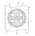
図6に、図3のB部に対応する詳細断面図を示す。また、図7に、図6の燃焼室15側から見た平面図を示す。
シリンダヘッド10の構成は第1実施例とほぼ同じであるが、ブッシュ20の代わりに燃焼室部材24を用いている点が異なる。
燃焼室部材24は、燃焼室15を構成する壁面を備え、図4のブッシュ20の機能を有した部品であり、ロアヘッド22に圧入又は接合にて備えられる。この燃焼室部材24は、鋳鉄又はアルミ展伸材等の材料から作られロアヘッド22よりも強度の高い部品である。
また、燃焼室部材24には、燃焼室15と、吸気ポート11及び排気ポート12の一部が設けられ、点火プラグ雌ネジ部14もシリンダヘッド10に組み付けた後に加工される。
第2実施例のエンジンは直列4気筒で4バルブのエンジンであるので、1つの燃焼室15に吸気ポート11及び排気ポート12が合計4カ所設けられる。図7は燃焼室15のうちの1つを示しており、点火プラグ雌ネジ部14の左右に、吸気ポート11及び排気ポート12が設けられていることが分かる。なお、隣り合う吸気ポート11の間、及び隣り合う排気ポート12の間を弁間16と呼ぶことにする。
この点火プラグ雌ネジ部14の加工については、凸部24aの長さが点火プラグ23を保持するのに十分な長さの点火プラグ雌ネジ部14を設けるだけの長さがあれば、最初から行われていても良い。
(Second embodiment)
Next, the configuration of the second embodiment will be described with reference to the drawings.
FIG. 6 shows a detailed cross-sectional view corresponding to part B of FIG. FIG. 7 shows a plan view seen from the
The configuration of the
The
The
Since the engine of the second embodiment is an in-line four-cylinder four-valve engine, a
As for the processing of the spark plug
燃焼室部材24は凸部24aと燃焼室部24bからなり、シリンダヘッド10と圧入又は接合されて一体化される際に、アッパヘッド21が備える第1保持穴21aとロアヘッド22の備える第2保持穴22aに凸部24aが、ロアヘッド22の備える保持凹部22bに燃焼室部24bが嵌り込む。
こうすることで、燃焼室部材24が接合層25を跨いでアッパヘッド21とロアヘッド22に備えられることになる。
なお、図6では、接合層25を凸部24aが跨いでいるが、燃焼室部24b部分が跨ぐように構成されても良い。
The
By doing so, the
In FIG. 6, the
第2実施例はこのような構成を有するので、以下の効果作用を示す。
まず、ロアヘッド22の材質を安価なものに変更することが可能となる。
第2実施例では、燃焼室部材24に燃焼室15を構成する壁面が形成されて、シリンダヘッド10に備えられる。したがって、エンジン稼働時には、燃焼室部材24に形成された燃焼室15の内壁面に高温高圧のガスが直接作用し、ロアヘッド22は高温高圧のガスに直接さらされなくなる。このため、ロアヘッド22の材質を安価なものに変更することが可能となる。
Since the second embodiment has such a configuration, the following effects are exhibited.
First, the material of the
In the second embodiment, a wall surface constituting the
また、燃焼室15の強度を高めることができる。
シリンダヘッド10に設けられる吸気ポート11及び排気ポート12は、1つの燃焼室15に対して4バルブのエンジンであれば、合計4つ設けられ、また、点火プラグ23を組み付けるための点火プラグ雌ネジ部14が空けられる。
すなわち、1つの燃焼室15には吸気ポート11及び排気ポート12に接続するための4つの穴と、点火プラグ雌ネジ部14が1つ設けられることになる。
そして、燃焼室15と吸気ポート11及び排気ポート12が接続される部分には、図示しないバルブシートが設けられることになる。
このバルブシートは、図示しないバルブシートリングが燃焼室15の内壁に圧入され、図示しないバルブがバルブシートリングに当接離間することで燃焼室15への吸排気を制御するものであり、通常はシリンダヘッド10の仕上げ加工時に設けられる。
しかし、このようなバルブシートリングを燃焼室15の内壁面に圧入するためには、鋳造後のシリンダヘッドに対して加工が必要となり、その厚み分のスペースを必要とするので、吸気ポート11及び排気ポート12の設けられる位置には、制限がある。
Further, the strength of the
In the case of a four-valve engine with respect to one
That is, one
A valve seat (not shown) is provided at a portion where the
In this valve seat, a valve seat ring (not shown) is press-fitted into the inner wall of the
However, in order to press-fit such a valve seat ring into the inner wall surface of the
一方、吸気ポート11及び排気ポート12のポートの径は性能上太い方が有利であり、特に吸気ポート11は吸気量を増やすために太く設けることが望ましい。従って、弁間16は必要な強度を持った上で狭く設けられることが望ましい。
燃焼室部材24自体に強度があれば、この弁間16を狭くすることが可能であり、性能向上に寄与することになる。
さらに、燃焼室部材24の材質を耐摺動性のある部材にするか、部分的に表面改質を行って耐摺動性を持たせれば、バルブシートリングを圧入する必要がなくなる。バルブシートリングは、冷やしバメという特殊な方法で圧入するケースが多く、組み付け工程のコストもかかる部品であるため、コストダウンには有効である。
On the other hand, it is advantageous that the diameters of the
If the
Further, if the material of the
また、シリンダヘッド10の設計自由度を上げる効果もある。
シリンダヘッド10に設ける接合層25がどの位置に来ても、燃焼室15の壁面に接合層25が現れることがない。このため接合面Y―Yを設ける位置の自由度が広くなる。
例えば図10のような構成で、アッパヘッド21及びロアヘッド22を同じ材質で鋳造したとする。
接合面Y―Yを図10で示すよりも下側であって燃焼室15を切断するような位置に持ってきた場合、エンジン稼働時に燃焼室15の内壁面は高温高圧の燃焼ガスにさらされるので、燃焼室15に現れた接合層25も当然この燃焼ガスにさらされることとなる。
また、アッパヘッド21及びロアヘッド22は圧力30を直接受けるほか、高温にさらされるので、アッパヘッド21及びロアヘッド22はそれぞれ膨張、収縮を繰り返すことになる。
このことにより、燃焼室15を構成する他の内壁面よりも、接合層25の部分は、強度が低いほか、熱に対しても弱いため、応力が集中し次第に劣化し亀裂が入ったり、窪みとなったりすることが考えられる。このような懸念があるため、図10及び図4でも、燃焼室15の図面上側に接合面Y―Yを持ってくる必要がある。
しかし、燃焼室部材24を用いれば、この問題を解決することができる。
すなわち、接合面Y―Yをどの位置に持ってきても、燃焼室15の内壁面に接合層25が現れることはなくなるので、シリンダヘッド10の設計の自由度を高くすることが可能となるというメリットがある。
また、燃焼室部材24は、単体で製造されれば同じ型から作られることとなるので、燃焼室15の容積が均一となり、エンジンの振動低減等に繋がる可能性もある。
In addition, there is an effect of increasing the design freedom of the
The joining
For example, it is assumed that the
When the joining surface YY is brought to a position lower than that shown in FIG. 10 and the
Further, since the
As a result, the
However, if the
That is, no matter where the joining surface YY is brought, the joining
Further, if the
以上に説明した、本発明のシリンダヘッド又はシリンダブロックの構造によれば、以下のような優れた作用、効果が得られる。
(1)第1実施例に記載されるシリンダヘッド10の構造において、燃焼室部材24が、エンジンの燃焼室15に面して設けられ、燃焼室部材24の外形が、燃焼室15から遠ざかる方向に縮径しているので、シリンダヘッド10に備えられるエンジンの燃焼室15において、エンジン稼働時に起こる燃料の燃焼、爆発による圧力30の影響を受けて、燃焼室部材24が上側に抜けたり、脱落したりすることがない。また、このように構成することで、燃焼室部材24自体が全体で応力を受けるので、強度上有利となる。
(2)(1)に記載されるシリンダヘッドの構造において、燃焼室部材24が、エンジンの燃焼室15のシリンダヘッド10側の壁面を構成することを特徴とするので、エンジンの燃焼室15を別部材で製造することが可能である。すなわち、シリンダヘッド10はアルミ合金で作られることが多いが、燃焼室部材24は鉄系の材料を用いて剛性を上げることが可能である。
このようにすることで、強度が必要な部材を集中することができるために、性能を向上させた上で、コストダウンにも寄与することが可能となる。
According to the structure of the cylinder head or cylinder block of the present invention described above, the following excellent actions and effects can be obtained.
(1) In the structure of the
(2) In the structure of the cylinder head described in (1), the
By doing in this way, since the member which needs intensity | strength can be concentrated, it becomes possible to contribute also to cost reduction while improving performance.
なお、本発明は前記実施形態に限定されるものではなく、その趣旨を逸脱しない範囲で様々な変更が可能である。
例えば、第1実施例及び第2実施例で示したシリンダヘッド10やブッシュ20、燃焼室部材24等の材質は、アルミニウム合金や鋳鉄に限らず、必要に応じて変更可能である。また、この接合に使用した接合剤も、適宜変更可能である。
In addition, this invention is not limited to the said embodiment, A various change is possible in the range which does not deviate from the meaning.
For example, the materials of the
10 シリンダヘッド
11 吸気ポート
12 排気ポート
13 ウォータジャケット
14 点火プラグ雌ネジ部
15 燃焼室
17 点火プラグ差し込み穴
20 ブッシュ
21 アッパヘッド
21a 第1保持穴
22 ロアヘッド
22a 第2保持穴
23 点火プラグ
25 接合層
30 圧力
DESCRIPTION OF
Claims (4)
部品を取り付ける部品取付穴を備えた部品取付部材が、前記第1構成部材に形成される第1保持穴と、前記第2構成部材に形成される第2保持穴に、前記分割面を跨いで挿入して固定されることを特徴とするシリンダヘッド又はシリンダブロックの構造。 In the structure of a cylinder head or a cylinder block in which a first component member and a second component member each having a dividing surface are molded, and the first component member and the second component member are joined at the dividing surface,
A component mounting member having a component mounting hole for mounting a component straddles the divided surface between a first holding hole formed in the first component member and a second holding hole formed in the second component member. A structure of a cylinder head or a cylinder block, which is inserted and fixed.
前記部品取付部材の前記部品取付穴に、部品螺合用のネジ溝が形成されることを特徴とするシリンダヘッド又はシリンダブロックの構造。 In the structure of the cylinder head or cylinder block according to claim 1,
A structure of a cylinder head or a cylinder block, wherein a thread groove for threading a part is formed in the part mounting hole of the part mounting member.
前記部品取付部材が、エンジンの燃焼室に面して設けられ、
前記部品取付部材の外形が、前記燃焼室から遠ざかる方向に縮径していることを特徴とするシリンダヘッドの構造。 In the structure of the cylinder head according to claim 1 or claim 2,
The component mounting member is provided facing the combustion chamber of the engine;
A cylinder head structure characterized in that an outer shape of the component mounting member is reduced in diameter in a direction away from the combustion chamber.
前記部品取付部材が、前記燃焼室のシリンダヘッド側の壁面を構成し、吸気ポート及び排気ポートを備えることを特徴とするシリンダヘッドの構造。
In the structure of the cylinder head according to any one of claims 1 to 3,
The cylinder head structure, wherein the component mounting member constitutes a wall surface of the combustion chamber on the cylinder head side and includes an intake port and an exhaust port.
Priority Applications (1)
| Application Number | Priority Date | Filing Date | Title |
|---|---|---|---|
| JP2006009937A JP2007192089A (en) | 2006-01-18 | 2006-01-18 | Structure for cylinder head and cylinder block |
Applications Claiming Priority (1)
| Application Number | Priority Date | Filing Date | Title |
|---|---|---|---|
| JP2006009937A JP2007192089A (en) | 2006-01-18 | 2006-01-18 | Structure for cylinder head and cylinder block |
Publications (1)
| Publication Number | Publication Date |
|---|---|
| JP2007192089A true JP2007192089A (en) | 2007-08-02 |
Family
ID=38447992
Family Applications (1)
| Application Number | Title | Priority Date | Filing Date |
|---|---|---|---|
| JP2006009937A Withdrawn JP2007192089A (en) | 2006-01-18 | 2006-01-18 | Structure for cylinder head and cylinder block |
Country Status (1)
| Country | Link |
|---|---|
| JP (1) | JP2007192089A (en) |
Cited By (1)
| Publication number | Priority date | Publication date | Assignee | Title |
|---|---|---|---|---|
| JP2009144585A (en) * | 2007-12-13 | 2009-07-02 | Toyota Motor Corp | Cylinder head cleaning method and cylinder head cleaning device |
-
2006
- 2006-01-18 JP JP2006009937A patent/JP2007192089A/en not_active Withdrawn
Cited By (1)
| Publication number | Priority date | Publication date | Assignee | Title |
|---|---|---|---|---|
| JP2009144585A (en) * | 2007-12-13 | 2009-07-02 | Toyota Motor Corp | Cylinder head cleaning method and cylinder head cleaning device |
Similar Documents
| Publication | Publication Date | Title |
|---|---|---|
| JP4400503B2 (en) | Partition plate for intake port, sand core for forming intake port and cylinder head | |
| US8146544B2 (en) | Engine cylinder head cooling features and method of forming | |
| US8176967B2 (en) | Method for producing a cast component with a cast-in pipe | |
| US20100065009A1 (en) | Piston and method for manufacturing the same | |
| US9784304B2 (en) | Connecting rod for an engine and method of making thereof | |
| JP2007192089A (en) | Structure for cylinder head and cylinder block | |
| JP2007192176A (en) | Four-cycle engine | |
| US8672018B2 (en) | Cylinder head and method | |
| KR101449304B1 (en) | Method for manufacturing piston of automobile engine | |
| JP4368794B2 (en) | Breaking structure of connecting rod | |
| JP2009036050A (en) | Cylinder block structure or cylinder block | |
| US10781769B2 (en) | Method of manufacturing an engine block | |
| WO2020145154A1 (en) | Method for manufacturing cylinder head | |
| JP2006322599A (en) | Con'rod and internal combustion engine and motor vehicle comprising the same | |
| KR100820464B1 (en) | Core for combustion chamber of cylinder head and intake/exhaust port | |
| JP2005125343A (en) | Crankshaft, its manufacturing method, and compressor | |
| JP4254053B2 (en) | Semi-wet cylinder block | |
| JP5461120B2 (en) | Cylinder block structure | |
| KR20080055438A (en) | Process for making cylinder head of vehicle | |
| JP2007247424A (en) | Cylinder liner, cylinder block and its manufacturing method | |
| JP4285203B2 (en) | Cylinder block | |
| JP2007187125A (en) | Structure for cylinder head or cylinder block | |
| JP7173166B2 (en) | cylinder head | |
| JP7011561B2 (en) | Manufacturing method of piston of internal combustion engine | |
| JP2012140909A (en) | Machining method of internal combustion engine |
Legal Events
| Date | Code | Title | Description |
|---|---|---|---|
| A621 | Written request for application examination |
Effective date: 20080401 Free format text: JAPANESE INTERMEDIATE CODE: A621 |
|
| A761 | Written withdrawal of application |
Free format text: JAPANESE INTERMEDIATE CODE: A761 Effective date: 20081224 |