JP2007190882A - Liquid ejection apparatus - Google Patents
Liquid ejection apparatus Download PDFInfo
- Publication number
- JP2007190882A JP2007190882A JP2006013602A JP2006013602A JP2007190882A JP 2007190882 A JP2007190882 A JP 2007190882A JP 2006013602 A JP2006013602 A JP 2006013602A JP 2006013602 A JP2006013602 A JP 2006013602A JP 2007190882 A JP2007190882 A JP 2007190882A
- Authority
- JP
- Japan
- Prior art keywords
- liquid
- switching
- ink
- ejection
- suction
- Prior art date
- Legal status (The legal status is an assumption and is not a legal conclusion. Google has not performed a legal analysis and makes no representation as to the accuracy of the status listed.)
- Granted
Links
Images


Classifications
-
- B—PERFORMING OPERATIONS; TRANSPORTING
- B41—PRINTING; LINING MACHINES; TYPEWRITERS; STAMPS
- B41J—TYPEWRITERS; SELECTIVE PRINTING MECHANISMS, i.e. MECHANISMS PRINTING OTHERWISE THAN FROM A FORME; CORRECTION OF TYPOGRAPHICAL ERRORS
- B41J2/00—Typewriters or selective printing mechanisms characterised by the printing or marking process for which they are designed
- B41J2/005—Typewriters or selective printing mechanisms characterised by the printing or marking process for which they are designed characterised by bringing liquid or particles selectively into contact with a printing material
- B41J2/01—Ink jet
- B41J2/17—Ink jet characterised by ink handling
- B41J2/175—Ink supply systems ; Circuit parts therefor
- B41J2/17503—Ink cartridges
- B41J2/1752—Mounting within the printer
-
- B—PERFORMING OPERATIONS; TRANSPORTING
- B41—PRINTING; LINING MACHINES; TYPEWRITERS; STAMPS
- B41J—TYPEWRITERS; SELECTIVE PRINTING MECHANISMS, i.e. MECHANISMS PRINTING OTHERWISE THAN FROM A FORME; CORRECTION OF TYPOGRAPHICAL ERRORS
- B41J2/00—Typewriters or selective printing mechanisms characterised by the printing or marking process for which they are designed
- B41J2/005—Typewriters or selective printing mechanisms characterised by the printing or marking process for which they are designed characterised by bringing liquid or particles selectively into contact with a printing material
- B41J2/01—Ink jet
- B41J2/135—Nozzles
- B41J2/165—Preventing or detecting of nozzle clogging, e.g. cleaning, capping or moistening for nozzles
- B41J2/16517—Cleaning of print head nozzles
- B41J2/1652—Cleaning of print head nozzles by driving a fluid through the nozzles to the outside thereof, e.g. by applying pressure to the inside or vacuum at the outside of the print head
- B41J2/16532—Cleaning of print head nozzles by driving a fluid through the nozzles to the outside thereof, e.g. by applying pressure to the inside or vacuum at the outside of the print head by applying vacuum only
-
- B—PERFORMING OPERATIONS; TRANSPORTING
- B41—PRINTING; LINING MACHINES; TYPEWRITERS; STAMPS
- B41J—TYPEWRITERS; SELECTIVE PRINTING MECHANISMS, i.e. MECHANISMS PRINTING OTHERWISE THAN FROM A FORME; CORRECTION OF TYPOGRAPHICAL ERRORS
- B41J29/00—Details of, or accessories for, typewriters or selective printing mechanisms not otherwise provided for
- B41J29/38—Drives, motors, controls or automatic cut-off devices for the entire printing mechanism
- B41J29/393—Devices for controlling or analysing the entire machine ; Controlling or analysing mechanical parameters involving printing of test patterns
Abstract
Description
本発明は、主として印刷データに対応してノズルからインク滴を吐出させて記録媒体にドットを形成させるインクジェット記録装置として用いられる液体噴射装置に関するものである。 The present invention relates to a liquid ejecting apparatus used as an ink jet recording apparatus that forms dots on a recording medium by ejecting ink droplets from nozzles mainly corresponding to print data.
ターゲットに液体を噴射する液体噴射装置には、インクを記録用紙に噴射して印刷を施すインクジェット式記録装置が知られている。 As a liquid ejecting apparatus that ejects liquid onto a target, an ink jet recording apparatus that performs printing by ejecting ink onto a recording sheet is known.
このようなインクジェット式記録装置は、印刷時の騒音が比較的小さく、しかも小さなドットを高い密度で形成できるため、昨今においてはカラー印刷を含めた多くの印刷に使用されている。このようなインクジェット式記録装置は、インクカートリッジからのインクの供給を受けるインクジェット式印字ヘッドと、記憶媒体を印字ヘッドの走査方向と垂直に移動させる紙送り機構を備え、印字ヘッドをキャリッジ上で記録媒体の幅方向(主走査方向)に移動させながら印字ヘッドに対して機械的圧力や熱エネルギーを発生させることで記録媒体に対してインク滴を吐出させることで記録が行われる。そしてキャリッジ上に、例えばブラックインクおよびイエロー、シアン、マゼンタの各カラーインクが吐出が可能な印字ヘッドを搭載し、ブラックインクによるテキスト印刷ばかりでなく、各インクの吐出割合を変えることにより、フルカラー印刷を可能としている。 Such an ink jet recording apparatus has a relatively low noise during printing and can form small dots with a high density. Therefore, these ink jet recording apparatuses are used in many printing including color printing in recent years. Such an ink jet recording apparatus includes an ink jet print head that receives supply of ink from an ink cartridge, and a paper feed mechanism that moves a storage medium perpendicular to the scanning direction of the print head, and records the print head on the carriage. Recording is performed by ejecting ink droplets onto the recording medium by generating mechanical pressure and thermal energy to the print head while moving in the width direction (main scanning direction) of the medium. On the carriage, for example, a print head capable of ejecting black ink and each color ink of yellow, cyan, and magenta is installed, and not only text printing with black ink but also full ink printing by changing the ejection ratio of each ink Is possible.
さらに昨今においては、カラー印刷時の品質を向上させるために、ライトシアンおよびライトマゼンタを加え、黒インクを含め合計6色のインクを使用する記録装置も提供されており、しかも大判紙など大量の印刷をインクカートリッジを交換することなく可能にするインクジェット式記録装置も要求されている。これに伴って各印字ヘッドにインクを供給するためのインクカートリッジの容量も大型化せざるを得ず、例えばキャリッジ上にではなく装置本体の両側の固定部に配置したカートリッジホルダ内に各インクカートリッジを着脱可能に装填し、カートリッジホルダよりフレキシブルチューブ等を介してインク供給路を介して印字ヘッドにインクを供給するような構成の記録装置も提供されている。 In addition, in recent years, in order to improve the quality of color printing, a recording device that uses light cyan and light magenta and uses a total of six colors including black ink has also been provided. There is also a need for an ink jet recording apparatus that makes it possible to replace the ink cartridge without replacing the ink cartridge. Along with this, the capacity of the ink cartridge for supplying ink to each print head is inevitably increased. For example, each ink cartridge is not placed on the carriage but in the cartridge holders arranged on the fixing portions on both sides of the apparatus main body. There is also provided a recording apparatus having a configuration in which the ink is removably loaded and ink is supplied from the cartridge holder to the print head via an ink supply path via a flexible tube or the like.
一方、これらのインクジェット式印字ヘッドは、その印字ヘッドの内部に形成された圧力発生室で加圧したインクをノズル開口からインク滴として記録用紙などの記録媒体に吐出させて印刷を行う関係上、ノズル開口からの溶媒の蒸発に起因するインク粘度の上昇やインクの固化により、また塵埃の付着、さらには気泡の混入などにより、印刷不良を起こすという問題を抱えている。このために、インクジェット式記録装置には、非印刷時に印字ヘッドのノズル開口を封止して乾燥を防止するためのキャッピング手段を備えている。 On the other hand, these ink jet print heads perform printing by ejecting ink pressurized in a pressure generating chamber formed inside the print head as ink droplets from a nozzle opening onto a recording medium such as recording paper. There is a problem that printing failure occurs due to an increase in ink viscosity or solidification of ink due to evaporation of the solvent from the nozzle opening, adhesion of dust, and mixing of bubbles. For this reason, the ink jet recording apparatus is provided with a capping unit for sealing the nozzle opening of the print head during non-printing to prevent drying.
このキャッピング手段は、非印刷時、すなわち印刷の休止時に前記したノズル開口のインクの乾燥を防止する気密の蓋として機能するだけでなく、ノズル開口に目詰まりが生じた場合には、キャッピング手段によりノズルプレートを封止し、キャッピング手段に接続された吸引ポンプからの負圧により、すべてのノズル開口からインクを吸引してノズル開口のインク固化による目詰まりや、インク流路内への気泡混入によるインク吐出不良を解消する機能をも備えている。 This capping means not only functions as an airtight lid for preventing the ink of the nozzle openings from drying out during non-printing, that is, when printing is suspended, but also when clogging occurs in the nozzle openings, The nozzle plate is sealed, and the negative pressure from the suction pump connected to the capping means sucks ink from all nozzle openings, causing clogging due to ink solidification of the nozzle openings, and air bubbles entering the ink flow path. It also has a function to eliminate ink discharge defects.
印字ヘッドの目詰まりや、インク流路内への気泡の混入状態を解消させるためのインクの強制的な吸引排出処理は、通常クリーニング操作と呼ばれ、装置の長時間の休止後に印刷を再開する場合に自動的に実行されたり、またユーザが記録画像の品質が悪化したのを解消するためにクリーニングスイッチを手動操作した場合などにインク滴を印字ヘッドへの負圧により排出させる操作が実行される。 Forcible suction and discharge of ink to eliminate clogging of the print head and air bubbles in the ink flow path is called a normal cleaning operation, and printing is resumed after a long pause of the device. In some cases, the operation is performed automatically, or when the user manually operates the cleaning switch to eliminate the deterioration of the recorded image quality. The
また、印字ヘッドに印刷とは関係のない駆動信号を印加して全ノズルからインク滴を空吐出させる機能も備えており、これはフラッシング操作と呼ばれ、クリーニング操作時のワイピング等で生じた印字ヘッドのノズル開口近傍の不揃いのメニスカスを回復させたり、また印刷中にインク滴の吐出量の少ないノズル開口において、インクの増粘による目詰まりを防止する目的で一定周期ごとに自動的に実行する操作である。 It also has a function to apply a drive signal unrelated to printing to the print head to eject ink droplets from all nozzles. This is called a flushing operation, and it is a print generated by wiping during a cleaning operation. Automatically executed at regular intervals in order to recover uneven meniscus near the nozzle opening of the head and to prevent clogging due to ink thickening at the nozzle opening where the amount of ink droplet ejection is small during printing. It is an operation.
インクジェット式記録装置は、印字ヘッドのノズル開口から吐出させるインク滴により多様な印刷に対応可能であるため、印刷目的に応じてインクカートリッジを交換することが可能である。すなわち、現に装着されているインクカートリッジとは異なる種類のインクによって印刷を行いたい場合には、その現に装着されているインクカートリッジを一旦取り外し、それに代えて、所望の種類のインクを有するインクカートリッジを装着し直すことが可能である。このような状況において、互いにインク種の異なるインクを使用して、同一のプリンタで随時、印字品質の異なる印刷を行いたいという要求が頻繁に起こり得ると考えられる。 Since the ink jet recording apparatus can cope with various types of printing with ink droplets ejected from the nozzle openings of the print head, the ink cartridge can be exchanged according to the printing purpose. That is, when printing is performed with a different type of ink from the currently installed ink cartridge, the currently installed ink cartridge is temporarily removed and replaced with an ink cartridge having a desired type of ink. It can be remounted. In such a situation, it is considered that there may frequently be a demand for printing with different print quality at any time using the same printer using different ink types.
このため、インク種の異なるインクに切換えるときに、流路中に残存しているインクを一旦洗浄するための洗浄液を記録ヘッド中に導入してから異なるインク種のインクを使用することも行われている。一方、上述したような装置の休止中に生じるノズル開口のインクの乾燥を防止するために、装置を休止する前に、キャッピング手段内に乾燥防止用の保湿液を吐出してからキャッピングすることも行われている。 For this reason, when switching to an ink of a different ink type, an ink of a different ink type is used after a cleaning liquid for once cleaning the ink remaining in the flow path is introduced into the recording head. ing. On the other hand, in order to prevent the ink at the nozzle openings from drying during the above-described apparatus pause, before the apparatus is paused, it may be capped after discharging a moisturizing liquid for preventing drying into the capping means. Has been done.
したがって、インク種の異なるインクを切換えるインク同士の切替えだけでなく、インクから洗浄液や保湿液等の機能液に切換えたり、反対に洗浄液や保湿液等の機能液からインクに切換えたりして使用することも提案されている。 Therefore, not only switching between inks of different ink types but also switching from ink to functional liquid such as cleaning liquid or moisturizing liquid, or conversely switching from functional liquid such as cleaning liquid or moisturizing liquid to ink is used. It has also been proposed.
このように、使用する液体を切換えた直後は、印字ヘッドおよびインク供給路には依然として、以前に装着されていた液体が、インク供給路や印字ヘッドに残存しているため、交換当初の印字品質が低下する。また、互いに種類の異なる液体同士の混合は、好ましくない化学反応やインクの増粘による目詰まりなどの問題が生じることもある。このような問題に対しては、上述したフラッシングやクリーニングだけでは根本的に対処することができない。 In this way, immediately after switching the liquid to be used, the previously installed liquid still remains in the ink supply path and the print head in the print head and the ink supply path. Decreases. In addition, mixing different types of liquids may cause problems such as an undesirable chemical reaction and clogging due to thickening of ink. Such a problem cannot be fundamentally addressed only by the flushing and cleaning described above.
そこで、複数の流体供給手段と前記複数の流体供給手段のうちから任意の流体供給手段を選択できる切替手段とをインクジェット記録装置に備えることによって、互いにインク種の異なるインクの混合を防ぐことが提案されている。
しかしながら、上記特許文献1および2は、液体の切替手段を用いて液体を効率よく使用しうるものであるが、切り替え時に流路内の液体が完全に切り替わるまでにはある程度の時間を要することが避けられず、流路内の液体が完全に切り替わったことを確認する手段や、液体の切り替え直後の吐出不良を確認する手段については全く言及されておらず、切り替え直後の初期の印字品質の確実性に問題が生じるおそれがある。
However, although
本発明は、このような事情に鑑みなされたもので、噴射する液体を切替えたときに、流路内の液体が完全に切り替わったことや、液体の切り替え直後の吐出不良を確認し、切り替え直後の初期の噴射品質を確保する液体噴射装置の提供を目的とする。 The present invention has been made in view of such circumstances. When the liquid to be ejected is switched, the liquid in the flow path is completely switched, or a discharge failure immediately after the liquid switching is confirmed. It is an object of the present invention to provide a liquid ejecting apparatus that ensures the initial ejection quality.
上記目的を達成するため、本発明の液体噴射装置は、噴射対象物に対してノズルから液体を噴射させる噴射ヘッドと、上記噴射ヘッドのノズル形成面をキャップするキャップ手段と、上記キャップ手段内の空間を吸引する吸引手段と、上記噴射ヘッドに供給する液体が切り替わったときに上記噴射ヘッドに供給される液体および/または噴射ヘッドから噴射された液体の特性を検知する検知手段と、上記検知手段の検知結果から液体の切替度合を判定するとともにその判定結果に応じて上記吸引手段の吸引を制御する制御手段とを備えたことを要旨とする。 In order to achieve the above object, a liquid ejecting apparatus of the present invention includes an ejecting head that ejects liquid from a nozzle onto an ejected object, a cap unit that caps a nozzle forming surface of the ejecting head, A suction means for sucking a space; a detection means for detecting characteristics of the liquid supplied to the ejection head and / or the liquid ejected from the ejection head when the liquid supplied to the ejection head is switched; and the detection means And a control means for controlling the suction of the suction means according to the determination result and determining the degree of switching of the liquid from the detection result.
本発明によれば、噴射ヘッドに供給する液体が切り替わったときに、上記噴射ヘッドに供給される液体および/または噴射ヘッドから噴射された液体の特性を検知し、その検知結果から液体の切替度合を判定し、その判定結果に応じて吸引手段の吸引を制御するため、噴射ヘッド内の液体が略完全に切り替わるのを確認してから噴射対象物への液体噴射を開始することができ、切り替え後の初期の噴射品質を確保することができる。 According to the present invention, when the liquid supplied to the ejecting head is switched, the characteristics of the liquid supplied to the ejecting head and / or the liquid ejected from the ejecting head are detected, and the switching degree of the liquid is determined from the detection result. In order to control the suction of the suction means in accordance with the determination result, it is possible to start the liquid ejection to the ejection target after confirming that the liquid in the ejection head is switched almost completely. The initial initial injection quality can be ensured.
本発明において、上記検知手段は、噴射ヘッドに供給される液体が流通する供給流路内の液体の特性を検知する場合には、噴射ヘッドに液体が供給される前の供給流路内での液体の特性を検知して切替度合を判定することから、確実に噴射ヘッド内の液体が切り替わるのを確認してから噴射対象物への液体噴射を開始することができ、切り替え後の初期の噴射品質を確保することができる。 In the present invention, when detecting the characteristic of the liquid in the supply flow path through which the liquid supplied to the ejection head flows, the detection means in the supply flow path before the liquid is supplied to the ejection head. By detecting the characteristics of the liquid and determining the degree of switching, it is possible to start the liquid ejection to the ejection target after confirming that the liquid in the ejection head has been switched reliably. Quality can be ensured.
本発明において、上記検知手段は、噴射ヘッドに設けられた複数のノズル列のうち最も外側に配置されたノズル列から噴射されている液体の特性を検知する場合には、外側に配置されたノズル列では中央付近に配置されたノズル列に比べて記録ヘッド内の流路が長いため、噴射ヘッド内で液体が滞留して切替前の液体が残りやすいため、この部分から実際に噴射された液体の特性を検知して切替度合を判定することから、確実に噴射ヘッド内の液体が切り替わるのを確認してから噴射対象物への液体噴射を開始することができ、切り替え後の初期の噴射品質を確保することができる。 In the present invention, when the detection means detects the characteristics of the liquid ejected from the outermost nozzle array among the plurality of nozzle arrays provided in the ejection head, the nozzle disposed on the outer side Since the flow path in the recording head is longer in the row than the nozzle row arranged near the center, the liquid stays in the jet head and the liquid before switching tends to remain, so the liquid actually ejected from this portion Therefore, it is possible to start the liquid injection to the injection target after confirming that the liquid in the injection head is switched reliably, and to detect the initial switching quality after switching. Can be secured.
本発明において、上記検知手段は、噴射ヘッドに設けられた各ノズル列において最も端部に配置されたノズルから噴射されている液体の特性を検知する場合には、最も端部に配置されたノズルでは中央付近に配置されたノズルに比べて噴射ヘッド内において相対的に液体が流れ難く、液体が滞留して切替前の液体が残りやすいため、この部分から実際に噴射された液体の特性を検知して切替度合を判定することから、確実に噴射ヘッド内の液体が切り替わるのを確認してから噴射対象物への液体噴射を開始することができ、切り替え後の初期の噴射品質を確保することができる。 In the present invention, when the detection means detects the characteristics of the liquid ejected from the nozzle disposed at the end most in each nozzle row provided in the ejection head, the nozzle disposed at the end most Compared to the nozzles located near the center, the liquid is relatively difficult to flow in the ejection head, and the liquid stays and the liquid before switching tends to remain, so the characteristics of the liquid actually ejected from this part are detected. Since the switching degree is determined, the liquid in the ejection head can be surely switched and then the liquid ejection to the ejection target can be started to ensure the initial ejection quality after the switching. Can do.
本発明において、上記検知手段は、噴射ヘッドから噴射対象物に対して液体が噴射されて形成された着弾痕の特性を検知する場合には、実際に噴射対象物に噴射された着弾痕の特性を検知して切替度合を判定することから、実際の着弾痕において問題のない程度まで噴射ヘッド内の液体が切り替わるのを確認してから噴射対象物への液体噴射を開始することができ、切り替え後の初期の噴射品質を確保することができる。 In the present invention, in the case where the detecting means detects the characteristic of the landing mark formed by ejecting the liquid from the injection head to the injection target, the characteristic of the landing mark actually injected onto the injection target Is detected and the degree of switching is determined, so that it can be confirmed that the liquid in the ejection head is switched to a level where there is no problem in the actual landing mark, and then liquid ejection to the ejection target can be started. The initial initial injection quality can be ensured.
本発明において、上記噴射ヘッドに対して液体を供給するための複数の液体供給手段と、上記複数の液体供給手段のうちから任意の液体供給手段を選択することにより噴射ヘッドに供給する液体を切り替える切替手段とを備え、上記制御手段は、上記切替手段により噴射ヘッドに供給する液体が切り替わったときに、液体の切替度合の判定と吸引の制御を実行する場合には、切替手段による液体の切り替えに応じて液体の切替度合の判定と吸引の制御を実行し、切り替え後の初期の噴射品質を確保することができる。 In the present invention, the liquid supplied to the ejection head is switched by selecting a plurality of liquid supply means for supplying the liquid to the ejection head and an arbitrary liquid supply means from the plurality of liquid supply means. Switching means. When the liquid supplied to the ejection head is switched by the switching means, the control means switches the liquid by the switching means when executing the determination of the degree of liquid switching and the suction control. Accordingly, the determination of the degree of switching of the liquid and the control of the suction are executed, and the initial ejection quality after the switching can be ensured.
本発明において、上記制御手段は、上記切替手段により、噴射ヘッドに供給する液体が記録用のインクに切り替わったときに液体の切替度合の判定と吸引の制御を実行する場合には、液体が記録用のインクに切り替わって、インクによる印字が行われる前に切替度合の判定と吸引の制御を実行することから、切り替え後の初期の噴射品質を確保することができる。 In the present invention, when the liquid supplied to the ejection head is switched to the recording ink by the switching unit, the control unit performs the determination of the degree of switching of the liquid and the suction control. Since the switching degree is determined and the suction control is executed before the ink printing is performed, the initial ejection quality after the switching can be ensured.
本発明において、上記制御手段は、上記切替手段により、噴射ヘッドに供給する液体が記録用のインク以外の機能性液体に切り替わったときには液体の切替度合の判定と吸引の制御を実行しない場合には、液体が記録用のインク以外の機能性液体に切り替わって、印字品質を問われないときに、切替度合の判定も吸引も行わないことから、装置のスループットを向上させるとともに、無駄な液体消費を防止することができる。 In the present invention, when the liquid supplied to the ejection head is switched to a functional liquid other than the recording ink by the switching means, the control means does not execute the determination of the degree of liquid switching and the suction control. When the liquid is switched to a functional liquid other than the recording ink and the print quality is not questioned, neither the switching degree nor the suction is performed, so that the throughput of the apparatus is improved and unnecessary liquid consumption is reduced. Can be prevented.
本発明において、上記制御手段は、上記切替手段により噴射ヘッドに供給する液体が切り替わった後に噴射対象物への記録動作を実行する場合に液体の切替度合の判定と吸引の制御を実行する場合には、インクによる印字が行われる前に切替度合の判定と吸引の制御を実行することから、切り替え後の初期の噴射品質を確保することができる。 In the present invention, the control means may execute determination of the degree of switching of the liquid and control of suction when performing a recording operation on the ejected object after the liquid supplied to the ejection head is switched by the switching means. Since the determination of the degree of switching and the suction control are executed before printing with ink is performed, the initial ejection quality after switching can be ensured.
本発明において、上記制御手段は、上記切替手段により噴射ヘッドに供給する液体が切り替わった後に噴射対象物への記録動作以外の機能性動作を実行する場合には液体の切替度合の判定と吸引の制御を実行しない場合には、印字品質を問われないときに切替度合の判定も吸引も行わないことから、装置のスループットを向上させるとともに、無駄な液体消費を防止することができる。 In the present invention, the control means determines the degree of switching of the liquid and performs suction when performing a functional operation other than the recording operation to the ejection target after the liquid supplied to the ejection head is switched by the switching means. When the control is not executed, the determination of the degree of switching and the suction are not performed when the print quality is not questioned, so that the throughput of the apparatus can be improved and wasteful liquid consumption can be prevented.
本発明において、上記制御手段は、上記切替手段により噴射ヘッドに供給する液体が切り替わったときに、液体の切替度合の判定および吸引と併せて、全ノズルの試し噴射を行って噴射不良ノズルを検出する噴射不良検出動作を実行し、噴射不良ノズルを検出したときにノズルの回復動作を実行する場合には、切替手段による液体の切り替えに応じて噴射不良ノズルを確実に回復させることから、切り替え後の初期の噴射品質を確保することができる。 In the present invention, when the liquid supplied to the ejection head is switched by the switching unit, the control unit performs a trial ejection of all the nozzles together with the determination of the degree of switching of the liquid and suction, and detects an ejection failure nozzle. When a defective nozzle detection operation is performed and when a defective nozzle is detected, the defective nozzle is reliably recovered according to the switching of the liquid by the switching means. The initial injection quality can be ensured.
本発明において、上記制御手段は、上記切替手段により、噴射ヘッドに供給する液体が記録用のインクに切り替わったときに噴射不良検出動作を実行する場合には、液体が記録用のインクに切り替わって、インクによる印字が行われる前に噴射不良ノズルの回復を行うことから、切り替え後の初期の噴射品質を確保することができる。 In the present invention, when the control unit performs the ejection failure detection operation when the liquid supplied to the ejection head is switched to the recording ink by the switching unit, the liquid is switched to the recording ink. Since the defective ejection nozzle is recovered before printing with ink, the initial ejection quality after switching can be ensured.
本発明において、上記制御手段は、上記切替手段により、噴射ヘッドに供給する液体が記録用のインク以外の機能性液体に切り替わったときには噴射不良検出動作を実行しない場合には、液体が記録用のインク以外の機能性液体に切り替わって、印字品質を問われないときに、噴射不良ノズルの回復を行わないことから、装置のスループットを向上させるとともに、無駄な液体消費を防止することができる。 In the present invention, when the liquid supplied to the ejection head is switched to a functional liquid other than the recording ink by the switching means, the control means does not execute the ejection failure detection operation, and the liquid is used for recording. When switching to a functional liquid other than ink and the print quality is not questioned, the ejection failure nozzle is not recovered, so that the throughput of the apparatus can be improved and wasteful liquid consumption can be prevented.
本発明において、上記制御手段は、上記切替手段により噴射ヘッドに供給する液体が切り替わった後に噴射対象物への記録動作を実行する場合に噴射不良検出動作を実行する場合には、インクによる印字が行われる前に噴射不良ノズルの回復を行うことから、切り替え後の初期の噴射品質を確保することができる。 In the present invention, in the case where the control unit performs the ejection failure detection operation when performing the recording operation on the ejection target after the liquid supplied to the ejection head is switched by the switching unit, the printing by the ink is performed. Since the defective injection nozzle is recovered before being performed, the initial injection quality after switching can be ensured.
本発明において、上記制御手段は、上記切替手段により噴射ヘッドに供給する液体が切り替わった後に噴射対象物への記録動作以外の機能性動作を実行する場合には噴射不良検出動作を実行しない場合には、印字品質を問われないときに噴射不良ノズルの回復を行わないことから、装置のスループットを向上させるとともに、無駄な液体消費を防止することができる。 In the present invention, the control means does not execute the ejection failure detection operation when performing a functional operation other than the recording operation on the ejection target after the liquid supplied to the ejection head is switched by the switching means. Since the ejection failure nozzle is not recovered when the print quality is not questioned, it is possible to improve the throughput of the apparatus and prevent wasteful liquid consumption.
本発明において、上記制御手段は、液体の切替度合の判定において、検知手段によって検知する液体の特性値の閾値を複数段階に設定し、上記複数段階の閾値に応じて複数段階の吸引モードで吸引するよう制御する場合には、無駄な吸引による液体消費を防止しながら確実に液体の切替を完了することができる。 In the present invention, the control means sets the threshold value of the characteristic value of the liquid detected by the detection means in a plurality of stages in the determination of the degree of liquid switching, and performs suction in a plurality of suction modes according to the threshold value in the plurality of stages. In the case of controlling to do so, the switching of the liquid can be completed reliably while preventing the liquid consumption due to useless suction.
本発明において、上記制御手段は、液体の切替後、噴射対象物への記録動作を実行する前に、液体の切替度合の判定と吸引制御を実行した後、液体の切替が完了した後に噴射不良検出動作を実行する場合には、相対的に多くの液体吸引を要する液体の切替度合の判定と吸引制御を先に行い、液体の切替が完了した後に噴射不良検出動作と噴射不良ノズルの回復を行うことから、液体の無駄な消費を防止しながら確実に液体の切替を行うとともにドット抜けも確実に防止する。 In the present invention, after the liquid is switched, before the recording operation to the ejection target is performed, the control means performs the liquid switching degree determination and the suction control, and then performs the ejection failure after the liquid switching is completed. When executing the detection operation, the determination of the degree of switching of the liquid that requires a relatively large amount of liquid suction and the suction control are performed first, and after the liquid switching is completed, the defective injection detection operation and the recovery of the defective injection nozzle are performed. Therefore, it is possible to surely switch the liquid while preventing wasteful consumption of the liquid and also reliably prevent the missing dot.
つぎに、本発明の実施の形態を詳しく説明する。 Next, embodiments of the present invention will be described in detail.
以下、本発明を具体化した液体噴射装置としてのインクジェット式プリンタの一実施形態を図1〜図9にしたがって説明する。 Hereinafter, an embodiment of an ink jet printer as a liquid ejecting apparatus embodying the present invention will be described with reference to FIGS.
図1は、インクジェット式プリンタのケース(図示せず)内に備えられたインクジェット式のプリンタ本体1の模式平面図である。
FIG. 1 is a schematic plan view of an ink jet printer
プリンタ本体1には、噴射ヘッドとしての記録ヘッド30(図6参照)に対して液体を供給するための複数の液体供給手段としてのカートリッジ2a〜2jが装着されている。各カートリッジ2a〜2jには、図示しないホルダおよびガイド板が設けられており、非印刷領域に配置されている。
The
上記カートリッジ2a〜2jは使用される液体数に対応しており、本実施形態は10個のカートリッジ2a〜2jが装着されている。カートリッジ2a〜2jの内部には液体が貯留された液体パック(図示せず)が設けられ、この液体パック内の液体がサブタンク5a〜5dを経由して記録ヘッド30に供給されるように構成されている。
The
上記各カートリッジ2a〜2jは、カートリッジチューブ15a〜15jを経由して、上記複数のカートリッジ2a〜2jのうちから任意のカートリッジ2a〜2jを選択することにより記録ヘッド30に供給する液体を切り替える切替手段16に連通している。上記切替手段16は、この例では10個のカートリッジ2a〜2jから4つのカートリッジを選択し、選択したカートリッジの液体を補給用チューブ4a〜4dを介してサブタンク5a〜5dおよび記録ヘッド30に供給するようになっている。
Each of the
上記サブタンク5a〜5dは、記録ヘッド30から噴射するインク数に対応させてキャリッジ3上に設けられる。本実施形態では、合計4個のサブタンク5a〜5dがキャリッジ3上に搭載されている。このサブタンク5a〜5dは、補給用チューブ4a〜4dを介して供給されたインク等の液体を、キャリッジ3下面に搭載された記録ヘッド30に対して供給可能に構成されている。
The
この例では、基本的にイエロー、マゼンタ、シアン、ブラックの4種類のインクを噴射し、それぞれのインクに対応して4本の補給用チューブ4a〜4dおよび4つのサブタンク5a〜5dが設けられている。そして、各サブタンク5a〜5dは、記録ヘッド30のノズル形成面に形成された4つのノズル列25a〜25d(図10参照)に対応してインク等を供給するようになっている。
In this example, basically four types of inks of yellow, magenta, cyan, and black are ejected, and four supply tubes 4a to 4d and four
また、サブタンク5a〜5dが搭載されるキャリッジ3は、キャリッジモータ6によって駆動され、タイミングベルト7を介し、走査ガイド部材8に案内されて、紙送り部材9の長手方向、すなわち記録用紙の幅方向である主走査方向に往復移動されるように構成されている。
The
一方、キャリッジ3の移動経路上における非印刷領域には、封止手段としてのキャップ部材10、吸引ポンプ11(図7参照)、廃液タンク12が配置されている。キャップ部材10は、ゴム等の可撓性素材により形成されている。そして、キャリッジ3が非印刷領域に移動したときに、上記キャップ部材10によって、記録ヘッド30のノズル形成面が封止されるように構成されている。このため、キャップ部材10は、プリンタ本体1の休止期間中において記録ヘッド30のノズル開口の乾燥を防止する蓋体として機能する。
On the other hand, a
また、上記キャップ部材10の底面は、チューブ13(図2参照)を介して吸引ポンプ11に接続されている。上記吸引ポンプ11は、キャップ部材10内の空間を吸引して吸引ポンプ11により生じる負圧を記録ヘッド30に作用させ、記録ヘッド30側から液体を排出できるように構成されている。さらに、キャップ部材10の印刷領域側には、ゴムなどの弾性素材によるワイピング部材14が配置されており、必要に応じて記録ヘッド30のノズル形成面を払拭して清掃できるように構成されている。
The bottom surface of the
この例では、上記10個のカートリッジ2a〜2j中、8個のカートリッジ2a〜2hが記録ヘッド30にインクを供給するためのインクカートリッジであり、残り2個のカートリッジ2i〜2jが記録ヘッド30に洗浄液または保湿液等の機能性液体を供給するための機能性液体カートリッジである。
In this example, among the ten
具体的には、カートリッジ2aを第1イエローインク(Y1)のインクカートリッジ、カートリッジ2bを第2イエローインク(Y2)のインクカートリッジ、カートリッジ2cを第1マゼンタインク(M1)のインクカートリッジ、カートリッジ2dを第2マゼンタインク(M2)のインクカートリッジ、カートリッジ2eを第1シアンインク(C1)のインクカートリッジ、カートリッジ2fを第2シアンインク(C2)のインクカートリッジ、カートリッジ2gを第1ブラックインク(B1)のインクカートリッジ、カートリッジ2hを第2ブラックインク(B2)のインクカートリッジ、とすることができる。
Specifically, the
また、カートリッジ2iを記録ヘッド30等の流路内を洗浄する際に供給する洗浄液(W)のカートリッジ、カートリッジ2jを装置の休止直前にキャップ部材10内に噴射して装置休止中のノズルの乾燥を防止するために供給する保湿液(D)のカートリッジ、とすることができる。
In addition, the cartridge of cleaning liquid (W) supplied when the
図2は、上記切替手段16として使用することができる切替弁の一例を示す。 FIG. 2 shows an example of a switching valve that can be used as the switching means 16.
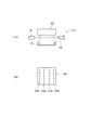
図2(a)は断面図、図2(b)は正面図である。201は切替弁筐体、202は出入口板、200は弁パッキンホルダ、210はゴム製の弁パッキン、220はバネである。弁パッキンホルダ200は弁パッキン210を保持している。切替弁筐体201内に装着されたバネ220が、弁パッキンホルダ200を押圧する。それによって、弁パッキンホルダ200と出入口板202との間に弁パッキン210が保持される。出入口板202には、その中央部に補給用チューブ4a〜4dを介して記録ヘッド30に接続される開口230が設けられている。開口230の周りには、それぞれカートリッジチューブ15a〜15jを介して種類の異なる液体のカートリッジ2a〜2jに接続される開口240、250,260,270が設けられている。
2A is a cross-sectional view, and FIG. 2B is a front view. 201 is a switching valve housing, 202 is an inlet / outlet plate, 200 is a valve packing holder, 210 is a rubber valve packing, and 220 is a spring. The
そして、図示の状態では、開口240と開口230が流路280を介して連通した状態であり、他の3つの開口250,260,270と開口230とは連通していない。この状態から、弁パッキンホルダ200の尾部290を回転すると、流路280の位置が変わり、記録ヘッド30に接続された開口230と連通する開口が開口240から開口250へ移動し、さらに尾部290を90度回転すると開口230と連通する開口が開口250から開口260へ移動する。さらに尾部290を90度回転すると開口230と連通する開口が開口260から開口270へ移動する。さらに尾部290を90度回転すると開口230と連通する開口が開口270から元の開口240へ移動する。このように、尾部290の回転の90度毎に記録ヘッド30と連通する開口が、開口240→開口250→開口260→開口270→開口240と切り替わる。このようにして記録ヘッド30に供給する液体の切替えを行うことができるのである。
In the state shown in the figure, the
本実施形態において、上記切替手段16は、図2の切替弁を噴射するインク色に対応して4つ備えている。4つの切替弁の各開口230は、4つの補給用チューブ4a〜4dとそれぞれ接続される。
In the present embodiment, the switching
また、4つの切替弁の各開口240、250,260,270は、カートリッジチューブ15a〜15jを介して種類の異なる液体のカートリッジ2a〜2jと接続する。
The
たとえば、イエローインクに対応する切替弁では、開口240、250をそれぞれ第1イエローインク(Y1)のカートリッジ2a、第2イエローインク(Y2)のカートリッジ2bと連通させ、開口260、270をそれぞれ洗浄液(W)のカートリッジ2i、保湿液(D)のカートリッジ2jと連通させる。
For example, in the switching valve corresponding to yellow ink, the
同様に、マゼンタインクに対応する切替弁では、開口240、250をそれぞれ第1マゼンタインク(M1)のカートリッジ2c、第2マゼンタインク(M2)のカートリッジ2dと連通させ、開口260、270をそれぞれ洗浄液(W)のカートリッジ2i、保湿液(D)のカートリッジ2jと連通させる。
Similarly, in the switching valve corresponding to magenta ink, the
また、シアンインクに対応する切替弁では、開口240、250をそれぞれ第1シアンインク(C1)のカートリッジ2e、第2シアンインク(C2)のカートリッジ2fと連通させ、開口260、270をそれぞれ洗浄液(W)のカートリッジ2i、保湿液(D)のカートリッジ2jと連通させる。
In the switching valve corresponding to cyan ink, the
さらに、ブラックインクに対応する切替弁では、開口240、250をそれぞれ第1ブラックインク(B1)のカートリッジ2g、第2ブラックインク(B2)のカートリッジ2hと連通させ、開口260、270をそれぞれ洗浄液(W)のカートリッジ2i、保湿液(D)のカートリッジ2jと連通させる。
Further, in the switching valve corresponding to the black ink, the
このようにすることにより、例えば、補給用チューブ4aおよびサブタンク5aに対応したノズル列25aには、第1イエローインク(Y1)、第2イエローインク(Y2)、洗浄液(W)、保湿液(D)を切替えて供給することができ、補給用チューブ4bおよびサブタンク5bに対応したノズル列25bには、第1マゼンタインク(M1)、第2マゼンタインク(M2)、洗浄液(W)、保湿液(D)を切替えて供給することができる。また、補給用チューブ4cおよびサブタンク5cに対応したノズル列25cには、第1シアンインク(C1)、第2シアンインク(C2)、洗浄液(W)、保湿液(D)を切替えて供給することができ、補給用チューブ4dおよびサブタンク5dに対応したノズル列25dには、第1ブラックインク(B1)、第2ブラックインク(B2)、洗浄液(W)、保湿液(D)を切替えて供給することができる。
By doing so, for example, the first yellow ink (Y1), the second yellow ink (Y2), the cleaning liquid (W), and the moisturizing liquid (D) are provided in the
このようにすることにより、要求する印字品質や使用する記録用紙の種類に応じて、第1インク(Y1、M1、C1、B1)と第2インク(Y2、M2、C2、B2)とを切替えて印字に使用することができる。例えば、染料インクと顔料インクを切替えて使用することができる。また、異なる種類のインクを切替えるときに、流路280や記録ヘッド30内で異種インクの混合が生ずると支障を来たす場合に、一旦洗浄液(W)に切替えて、記録ヘッド30内や流路280内に残存するインクを排出して洗浄することが行われる。これにより、ノズル数を増加することなく、同一の印字ヘッドを使用して多種類のインクを使用することが可能である。
In this way, the first ink (Y1, M1, C1, B1) and the second ink (Y2, M2, C2, B2) are switched according to the required print quality and the type of recording paper to be used. Can be used for printing. For example, the dye ink and the pigment ink can be switched and used. In addition, when different types of ink are switched, if mixing of different types of ink occurs in the
また、装置を休止する直前には、保湿液(D)に切替えてキャップ部材10内に保湿液を噴射し、湿潤状態でキャッピングすることにより、装置休止中のノズルの乾燥を防止することが可能となる。
Further, immediately before the apparatus is stopped, it is possible to prevent drying of the nozzle during the apparatus stop by switching to the moisturizing liquid (D) and injecting the moisturizing liquid into the
なお、上記切替手段16は、電磁気を利用した電磁弁であってもよい。また、上記プリンタ本体1においては、理解を容易にするために切替手段16を独立して配置しているが、必ずしも独立に配置する必要はなく、記録ヘッド30に配備してもよく、また、カートリッジ2a〜2jに配備してもよい。
The switching means 16 may be an electromagnetic valve using electromagnetics. Further, in the printer
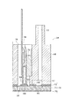
図3は、キャリッジ3に搭載されて液体としてインクを噴射する記録ヘッド30と、その上部に装着されるサブタンク5a〜5dとを断面状態で示したものである。
FIG. 3 shows the
上記記録ヘッド30は、噴射する液体を濾過するフィルタ32を備えたフィルタケース33と、上記フィルタケース33の下面に取り付けられたヘッド本体34とを備えて構成されている。
The
上記フィルタケース33の上面には、4本の中空状のインク供給針31が直立状態に配置されており、上記フィルタケース33内に形成された各インク連絡流路35は、それぞれ各インク供給針31内のインク流路に連通されている。各インク供給針31の頂部にはインク導入孔31aが形成されており、サブタンク5a〜5dからのインクは、このインク導入孔31aを介してインク供給針31内に導入され、上記インク連絡流路35を介してヘッド本体34に供給され、各ノズル列25a〜25dのノズル開口から噴射される。したがって、各サブタンク5a〜5d、インク供給針31、インク連絡流路35が、各ノズル列25a〜25dに対応している。
Four hollow ink supply needles 31 are arranged in an upright state on the upper surface of the
上記各インク供給針31はサブタンク5a〜5dの配置状態に合わせて所定の間隔を隔てて並ぶよう配置されている。一方、ヘッド本体34がインクの供給を受ける幅寸法はそれよりも小さいため、内側に配置されたインク連絡流路35よりも外側に配置されたインク連絡流路35の方が流路の傾斜角が大きくなっている。このような構造から、内側に配置されたノズル列25b,25cよりも、外側に配置されたノズル列25a,25dの方が液体の滞留が起こりやすい構造になっている。
The ink supply needles 31 are arranged so as to be arranged at a predetermined interval according to the arrangement state of the
図4は、上記ヘッド本体34を示す図である。
FIG. 4 is a diagram showing the head
図に示すように、上記ヘッド本体34は、圧力発生手段としての圧電振動子64が収容されるヘッドケース66と、このヘッドケース66のユニット固着面に接着剤等で固着される流路ユニット76とを備えている。この図では、1つのノズル列25a〜25dに対応した1つのインク噴射機構を示して説明するが、この例のヘッド本体34では4つのノズル列25a〜25dに対応してインク噴射機構が4つ設けられている。
As shown in the figure, the head
上記流路ユニット76は、圧力発生室69を含む流路空間が形成された流路形成基板71と、上記流路形成基板71の一面に積層されて圧力発生室69内のインクを噴射するノズル36が形成されたノズルプレート70と、上記流路形成基板71の他面に積層されて圧力発生室69を含む流路空間を封止する振動板(封止板)72とが積層されて構成されている。
The flow path unit 76 includes a flow path forming substrate 71 in which a flow path space including the
上記ノズルプレート70は、所定の解像度(ドットピッチ)に対応したピッチPでノズル36が複数列設されて1列のノズル列25a〜25dが形成され、それぞれのノズル36からインク滴を噴射するようになっている。このノズルプレート70は、ステンレス板から形成されている。
The
上記流路形成基板71は、上記各ノズル36に連通する圧力発生室69が列設されている。また、後述するインク貯留室67の圧力変動を逃がすダンパ室65が形成されている。上記圧力発生室69およびダンパ室65となる空間は、流路形成基板71の振動板72側に凹部として形成されている。上記流路形成基板71は、この例ではSi単結晶基板をエッチングすることにより形成されている。
In the flow path forming substrate 71,
上記振動板72は、ポリフェニレンサルファイドフィルムからなり、ステンレス板製の島部63等がラミネートされて形成されている。また、この振動板72には、後述するインク貯留室67のインクを各圧力発生室69に供給するためのインク供給口68が形成されている。
The
そして、上記流路形成基板71の一面にノズルプレート70が積層され、他面に振動板72が島部63を外側に配置するように積層されて流路ユニット76が構成されている。上記流路形成基板71、ノズルプレート70、振動板72に接着剤が塗布され、所定の高温に加熱保持して接合したのち室温まで冷却することにより、流路ユニット76がつくられる。
The
一方、上記ヘッドケース66は、熱硬化性樹脂や熱可塑性樹脂が射出成形されてなり、そのユニット固着面には、上記圧力発生室69の列に対応して各圧力発生室69に対して供給するインクを貯留する共通のインク貯留室67が、上記圧力発生室69の列に沿って配置されるよう形成されている。また、上記ヘッドケース66には、上記インク連絡流路35と連通してインク貯留室67にインクを供給する1本のインク供給路77が形成されている。
On the other hand, the
また、上記ヘッドケース66は、ノズル列25a〜25d方向に延びて上下に貫通する収容空間78が形成され、この収容空間78に振動子ユニット75が収容されるようになっている。
The
上記振動子ユニット75は、固定板73の先端に、上記各圧力発生室69に対応するよう列設された棒状の圧電振動子64が固着され、上記各圧電振動子64に、吐出信号を入力するためのフレキシブルケーブル74が接続されて構成されている。上記圧電振動子64は、縦振動モードの圧電振動子64である。
In the
そして、上記ヘッドケース66のユニット固着面に、流路ユニット76の振動板72側が接着剤で接合された状態で、圧電振動子64の先端面が振動板72の島部63に固着されるとともに、固定板73がヘッドケース66に接着固定されることにより、ヘッド本体34が構成されている。
The tip surface of the
上記構成のヘッド本体34は、駆動回路で発生させた駆動信号をフレキシブルケーブル74を介して圧電振動子64に入力することにより、圧電振動子64が長手方向に伸縮される。この圧電振動子64の伸縮により、振動板72の島部63を振動させて圧力発生室69内の圧力を変化させ、圧力発生室69内のインクをノズル36からインク滴として吐出させるようになっている。
In the head
そして、上記ヘッド本体34は、上述したインク吐出構造がイエロー(Y)、マゼンタ(M)、シアン(C)、ブラック(B)の4色のインクごとに設けられ、4つのノズル列25a〜25dからそれぞれイエロー(Y)、マゼンタ(M)、シアン(C)、ブラック(B)の各色のインクを吐出するように構成される。
The head
このような構造であるため、各ノズル列25a〜25dを構成するノズル36のうち両端部のノズル36においては、液体が滞留しやすい構造となっている。
Because of this structure, the
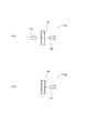
図5は、液体の切替度合の判定に用いる検知手段17の具体例を示したものである。 FIG. 5 shows a specific example of the detecting means 17 used for determining the degree of switching of the liquid.
本実施形態では、上記記録ヘッド30に供給する液体が切り替わったときに上記記録ヘッド30に供給される液体の特性を検知する検知手段17と、上記検知手段17の検知結果から液体の切替度合を判定するとともにその判定結果に応じて上記吸引ポンプ11の吸引を制御する制御手段とを備えている。
In the present embodiment, when the liquid supplied to the
図5(A)に示す検知手段17は、記録ヘッド30に供給される液体が流通する供給流路18内の液体の特性を検知するものであり、透明パイプである供給流路18を挟んで発光素子19と受光素子20を対面させて配置し、発光素子19の光を供給流路18内の液体を通過させて受光素子20で受光し、受光した光の特性を検知する投下方式のセンサである。そして検知した特性値により、記録ヘッド30に供給する液体を切替えたときに、供給流路18内に存在する液体がどの程度切り替わったかを示す切替度合を判定する。
The detection means 17 shown in FIG. 5A detects the characteristics of the liquid in the
このような検知手段17aとしては、例えば、非分散形赤外線吸収式センサや、赤外線パルス透過光方式センサを適用することができる。非分散形赤外線吸収式センサとは、光源から放射される全波長の赤外線をそのまま用い、液体が各々固有の赤外線波長を吸収する性質を利用して、液体に赤外線を放射したときにどの波長がどれくらい吸収されたかを検知して、液体の切り替わり度合を測る方式である。また、赤外線パルス透過光方式センサとは、赤外LEDから直接光を受光素子で受ける透過光方式のセンサであり、入射光の強度(Po)、透過光の強度(Px)として、吸光度=log(Po/Px)を求め、液体の切り替わり度合を測る方式である。 As such a detecting means 17a, for example, a non-dispersive infrared absorption sensor or an infrared pulse transmission light sensor can be applied. A non-dispersive infrared absorption sensor uses infrared light of all wavelengths emitted from a light source as it is, and utilizes the property that each liquid absorbs a specific infrared wavelength. This is a method that measures how much the liquid has changed by detecting how much is absorbed. The infrared pulse transmitted light type sensor is a transmitted light type sensor that receives light directly from an infrared LED by a light receiving element. As the intensity of incident light (Po) and the intensity of transmitted light (Px), absorbance = log. In this method, (Po / Px) is obtained and the degree of liquid switching is measured.
図5(B)に示す検知手段17bは、記録ヘッド30に供給される液体が流通する供給流路18内の液体の特性を検知するものであり、透明パイプである供給流路18に対してカラーCCDセンサ21を配置し、供給流路18内の液体の色特性を検知する方式のセンサである。そして、検知した色のRGBそれぞれ0〜255段階の強さである色特性値により、記録ヘッド30に供給する液体を切替えたときに、供給流路18内に存在する液体がどの程度切り替わったかを示す切替度合を判定する。
The detecting means 17b shown in FIG. 5B detects the characteristics of the liquid in the
上記検知手段17a、17bは、例えば、記録ヘッド30に液体を供給する補給用チューブ4a〜4dに設けることができるが、サブタンク5a〜5dの下流側の流路に設けることもできるし、記録ヘッド30内の流路に設けるようにしてもよい。また、上記検知手段17a、17bはいずれか一方だけ使用することもできるし、双方を併用することもできる。
The detection means 17a and 17b can be provided, for example, in the replenishment tubes 4a to 4d that supply the liquid to the
そして、切替度合の判定は、検知手段17a、17bにより検知される液体の特性値が、所定の閾値を超えることにより、流路内の液体が切り替わったと判定することができる。そして、検知手段17a、17bにより検知される液体の特性値が予め設定した所定の閾値を超えていないときは、キャップ部材10によるキャッピングと吸引ポンプ11による吸引を行って、記録ヘッド30内に残存している切替え前の液体の吸引排出と、切替え後の液体の記録ヘッド30への供給を行うことができる。
The determination of the degree of switching can be made when the liquid in the flow path is switched when the characteristic value of the liquid detected by the detection means 17a, 17b exceeds a predetermined threshold. When the characteristic value of the liquid detected by the detection means 17a and 17b does not exceed a predetermined threshold value set in advance, capping by the
このとき、閾値を複数段階に設定しておいて、検知した特性値がどのレベルにあるかによって吸引ポンプ11による吸引量や吸引時間を変えるよう制御することもできる。例えば、閾値をS0>S1>S2と3段階に設定し、液体が完全に切り替わった状態をS0とする。さらに吸引モードもK2>K1>K0と吸引度合を3段階に設定する。そして、検知した特性値がS2未満のときは最も強い吸引モードK2で吸引し、検知した特性値がS2以上S1未満のときは2番目に強い吸引モードK1で吸引し、検知した特性値がS1以上S0未満のときは3番目の吸引モードK0で吸引し、検知した特性値がS0以上のときは吸引せずに印字動作に進むような制御を行うことができる。
At this time, the threshold value can be set in a plurality of stages, and control can be performed so as to change the suction amount and the suction time by the
図6は、ドット抜け検出に用いる断続部検出手段22の一例を示す。 FIG. 6 shows an example of the intermittent part detection means 22 used for dot missing detection.
この記録装置は、上記切替手段16により記録ヘッド30に供給する液体が切り替わったときに、液体の切替度合の判定および吸引と併せて、全ノズルの試し噴射を行って噴射不良ノズルを検出する噴射不良検出動作としてのドット抜け検出動作を実行し、噴射不良ノズルを検出したときにノズルの回復動作を実行するドット抜け検出機構を備えている。
In this recording apparatus, when the liquid to be supplied to the
上記ドット抜け検出は、例えば、給紙された1枚目またはロール紙先頭部を試し噴射用紙とし、記録ヘッド30の全ノズルからのインク噴射で構成されるラインパターンを重ならないように試し噴射用紙上に形成し、形成されたラインパターンの断続部の有無を断続部検出手段22で検出し、断続部の有るラインパターンが形成された場合にノズルの目づまりを回復する回復動作を行うものである。
The dot missing detection is performed by using, for example, the first sheet fed or the leading portion of the roll paper as the test ejection paper, and the test ejection paper so as not to overlap the line patterns formed by the ink ejection from all the nozzles of the
上記断続部検出手段22は、発光・受光素子を具備した反射光検出型フォトインタラプタであり、記録ヘッド30が取り付けられたキャリッジ3の記録紙23と対面する面に取り付けられている。
The intermittent portion detection means 22 is a reflected light detection type photointerrupter provided with light emitting / receiving elements, and is attached to a surface facing the
ラインパターンの形成は、試し噴射用紙とした記録紙23上に、キャリッジ3を移動させながら記録ヘッド30の各ノズル列25a〜25dの全ノズルから試し噴射して直線のラインパターン24を各々形成する。そして、上記断続部検出手段22を直線のラインパターン24上に移動させ、記録紙を順次図示しない紙送り機構によりパターン長さ分各々のパターンについて搬送を繰り返し、ラインパターン24の断続部すなわちノズルの目づまりによる断続部や不吐出部の有無を光学的に検知する。
The line pattern is formed on the
そして、断続部を検知したら、キャップ部材10によるキャッピングと吸引ポンプ11によるクリーニングモードによる吸引を行って、ノズル目詰まりの回復操作を行う。
When the intermittent portion is detected, capping by the
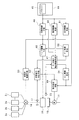
図7は、上記記録装置のシステム構成の一例を示すブロック図である。 FIG. 7 is a block diagram showing an example of the system configuration of the recording apparatus.
ここで説明する印刷制御手段46、保湿制御手段50、洗浄制御手段51、ヘッド駆動手段48、ドット抜け検出制御手段47、クリーニング制御手段54、吸引制御手段49、切替度合判定手段52、切替弁制御手段53、フラッシング制御手段55は、本発明の制御手段として機能するものである。 The printing control means 46, the moisturizing control means 50, the cleaning control means 51, the head driving means 48, the dot dropout detection control means 47, the cleaning control means 54, the suction control means 49, the switching degree determination means 52, and the switching valve control described here. The means 53 and the flushing control means 55 function as the control means of the present invention.
図において、44はホストコンピュータであり、プリンタドライバ45が内蔵され、このプリンタドライバ45のユーティリティ上で入力装置(図示せず)からの入力によって記録紙のサイズ,モノクロ/カラー印刷の選択,記録モードの選択,フォント等のデータおよび印字指令等を入力しうるように構成されている。また、上記プリンタドライバ45のユーティリティにおいて、切替手段16に対する液体切替の指示指令も入力しうるように構成されている。
In the figure, a
印字指令の入力により、プリンタドライバ45からは印刷制御手段46に対して液体噴射データである印刷データが送出されるようになっている。また、印刷制御手段46は印刷データに基づいてビットマップデータを生成し、ヘッド駆動手段48により駆動信号を発生させて圧電振動子に入力し、記録ヘッド30からインク滴を吐出させるようになっている。このとき、印刷制御手段46からの指示により図示しない紙送り制御手段は同じく図示しない紙送りモータを制御して記録紙の副走査方向への移動制御を行う。また、印刷制御手段46からの指示により図示しないキャリッジ制御手段はパルスモータであるキャリッジモータ6を制御してキャリッジ3の主走査方向への往復移動制御を行う。
In response to the input of the print command, the
上記ヘッド駆動手段48は、駆動手段として機能するもので、印刷データに基づく駆動信号のほかに、フラッシング制御手段55からのフラッシング指令信号を受けてフラッシングのための駆動信号を記録ヘッド30に出力する。このフラッシング動作により、フラッシングボックスとしてのキャップ部材10に対してノズルから印字とは無関係のインクを噴射することにより、ノズル近傍の増粘インクを排出して記録ヘッド30の噴射特性を回復する。
The
ここで、ノズルの吐出能力が低下するメカニズムについて説明すると、印刷実行中は記録ヘッド30のノズル面がキャップ部材10から開放された状態となり、加えてキャリッジ3で往復移動されている。このような状態でインクの吐出がなければ、ノズルの開口部に存在するインクから溶媒が蒸発して徐々にその粘度が高くなり、吐出能力が低下するのである。そして、印刷中に頻繁にインク滴を吐出しているノズルは、新しいインクが順次供給されて目詰まりはあまり生じないが、インク滴を吐出する機会が少ないノズルでは目詰まりを生じやすい。したがって、インクの吐出量が少なく空送時間が長いノズルほど増粘が進行し、その程度はノズル毎にばらつきがある。
Here, the mechanism by which the discharge capacity of the nozzles is reduced will be described. During printing, the nozzle surface of the
なお、この例では、噴射ヘッドが噴射する液体がインクであり、インクの増粘によりノズルの噴射能力が低下する場合を説明したが、噴射特性の低下するメカニズムは、噴射する液体の種類によって異なる場合があり、本発明は、低下したノズルの噴射特性を液体の噴射で回復しうるものであれば、インクに限らず種々の液体を噴射する装置に適用できる趣旨である。 In this example, the case has been described in which the liquid ejected by the ejection head is ink, and the ejection capability of the nozzle is reduced due to the increased viscosity of the ink. However, the mechanism by which the ejection characteristics are degraded varies depending on the type of liquid to be ejected. In some cases, the present invention is applicable not only to ink but also to an apparatus that ejects various liquids as long as the lowered nozzle ejection characteristics can be recovered by liquid ejection.
キャリッジ制御手段は、印刷動作中にキャリッジ3を主走査方向に往復移動させる移動制御を行うほか、所定のフラッシングタイミングにおいてキャリッジを印刷領域以外のフラッシングポジションに移動させ、記録ヘッド30をキャップ部材10に対面させてフラッシング動作を行う位置に移動する移動制御を行う。
The carriage control means performs movement control for reciprocating the
また、上記キャリッジ制御手段は、装置の電源オフのときや吸引動作を行う際には、記録ヘッド30をキャップ部材10の位置に移動させる移動制御を行う。
The carriage control unit performs movement control for moving the
この吸引動作は、プリンタ本体1を最初に使用するときに、最初にカートリッジ2a〜2jを装着した際、記録ヘッド30やサブタンク5a〜5d等の流路にインクを最初に充填する初期充填動作の際に実行される。また、カートリッジ2a〜2jを交換したときや、使用していたカートリッジ2a〜2jを一旦取り外して再装填するときには、交換や再装填に伴って記録ヘッド30の流路内に空気が混入して正常な吐出ができなくなるため、混入した気泡を記録ヘッド30から強制吸引して除去するために実行される。
This suction operation is an initial filling operation in which the ink is first filled into the flow path of the
上記吸引動作は、プリンタ本体1を使用せずに放置しているときは、キャップ部材10でノズル形成面を封止した状態であっても、図示しない放置タイマで計測した放置時間(前回の電源オフから今回の電源オンまでの時間)が長いと徐々にノズルの開口部に存在するインクから溶媒が蒸発してその粘度が高くなり、吐出能力が低下するので、それを回復するクリーニングのために電源オン時に、クリーニング制御手段54による制御によりクリーニングモードによる吸引が実行される。また、印刷動作を継続していると、流路内に残存した気泡が徐々に内部のフィルタ上流部に溜まることがあるため、定期的に気泡を強制吸引して除去するクリーニングのため、クリーニング制御手段54による制御によりクリーニングモードによる吸引が実行されることもある。
In the suction operation, when the printer
上記吸引動作は、ドット抜け検出制御手段47によって制御される上述したドット抜け検出の際に、断続部検出手段22によってラインパターン24の断続部すなわちノズルの目づまりによる断続部や不吐出部の存在を検知した場合、クリーニング制御手段54による制御によりキャップ部材10によるキャッピングと吸引ポンプ11によるクリーニングモードによる吸引を行って、ノズル目詰まりの回復操作を行う。
The suction operation is performed by the intermittent portion detection means 22 when the above-described dot drop detection is controlled by the dot drop detection control means 47, so that the intermittent portion of the
このとき、断続部すなわち噴射不良のノズルが存在するノズル列25a〜25dが1〜3つのときは、断続部のないノズル列25a〜25dに対応するサブタンク5a〜5dに設けた図示しない封止弁を閉じることにより、噴射不良ノズルがあるノズル列25a〜25dに対応する流路のみ液体の吸引を行って、無駄な液体消費をしないようにすることができる。
At this time, when there are 1 to 3
また、上記吸引動作は、切替弁制御手段53により上述した切替弁を制御して記録ヘッド30の各ノズル列25a〜25dに供給する液体を切替えるときに、切替弁の切替後、キャップ部材10で記録ヘッド30のノズル形成面をキャッピングして吸引ポンプ11で吸引することにより、記録ヘッド30内や流路内に残存している切替前の液体をノズル開口から吸引して排出し、切替後の液体を記録ヘッド30内に供給するために実行される。
The suction operation is performed by the
このとき、切り替えるノズル列25a〜25dが1〜3つのときは、切り替えていないノズル列25a〜25dに対応するサブタンク5a〜5dに設けた図示しない封止弁を閉じることにより、切り替えたノズル列25a〜25dに対応する流路のみ液体の吸引を行って、無駄な液体消費をしないようにすることができる。
At this time, when the number of
また、上記吸引動作は、切替度合判定手段52によって制御される上述した切り替え度合の判定により、検知手段17により検知される液体の特性値が予め設定した所定の閾値を超えていないときは、キャップ部材10によるキャッピングと吸引ポンプ11による吸引を行って、記録ヘッド30内に残存している切替え前の液体の吸引排出と、切替え後の液体の記録ヘッド30への供給を行う際に実行される。
The suction operation is performed when the characteristic value of the liquid detected by the detecting
上記各吸引動作は、初期充填時、カートリッジ2a〜2jの交換時、クリーニング時、ドット抜け検出時等のクリーニングモードでの吸引や、切替度合判定時等、状況によって吸引条件が異なる場合があるため、吸引制御手段49による制御で吸引ポンプ11の回転数や稼働時間を制御することにより、クリーニングモード、モードK2、モードK1、モードK0等、所定の吸引モードでの吸引が実行される。
The above suction operations may differ depending on the situation, such as suction in cleaning mode such as initial filling,
そして、上記吸引動作は、メンテナンス制御手段49により、つぎのように制御される。すなわち、キャリッジ3をキャップ部材10に対面させる位置に移動させるとともに、キャップ部材10を図示しないメンテナンスモータの動作により例えばカム機構等により上昇させて記録ヘッド30のノズル形成面をキャップ部材10で封止し、メンテナンスモータによって駆動される吸引ポンプ11の作用によりキャップ部材10内を吸引してノズルからインク等を強制的に排出させる。
The suction operation is controlled by the maintenance control means 49 as follows. That is, the
所定時間の吸引を行った後、図示しない弁機構によりキャップ部材10内を大気開放した状態で吸引ポンプ11を駆動して空吸引を行ってキャップ部材10内の空間に残存したインクを排出する。その後、キャップ部材10を下降させると、この状態ではノズル形成面にインクが付着しているため、メンテナンスモータの駆動によりワイピング部材14をその先端部がノズル形成面に接触し得る位置まで上昇させたのち、キャリッジ3を移動制御することにより、ノズル形成面に付着したインクをワイピング部材14で払拭することが行われる。
After performing suction for a predetermined time, the
保湿制御手段50は、装置を休止する直前に、所定のノズル列25a〜25dの液体を保湿液(D)に切替えて、キャップ部材10内に保湿液を噴射し、湿潤状態でキャッピングする動作を制御する。
Immediately before stopping the apparatus, the moisturizing control means 50 switches the liquid in the
洗浄制御手段51は、異なる種類のインクを切替えるときに、一旦洗浄液(W)に切替えて記録ヘッド30内や流路内に残存するインクを排出して洗浄する洗浄動作を制御する。
When switching between different types of ink, the
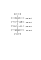
図8は、上記プリンタ本体1において、切替手段16により液体の切替が行われたときの切替処理動作の一例を示すフローチャートである。
FIG. 8 is a flowchart showing an example of a switching process operation when the liquid is switched by the switching
切替弁制御手段53による切替手段16の制御が行われて記録ヘッド30に供給する液体が切り替わると、まず、当該切替操作がインクへの切替であるか否かを判断する(S10)。
When the switching
このインクへの切り替えとは、インク→インクへの切り替えの場合と、保湿液または洗浄液等の機能性液体→インクへの切り替えの場合とがある。反対に、インクへの切替でない切り替えとは、洗浄液または保湿液すなわち機能性液体への切り替えであり、インク→保湿液または洗浄液等の機能性液体への切り替えの場合と、保湿液→洗浄液または洗浄液→保湿液という機能性液体同士の切り替えの場合とがある。切替操作がインクへの切替であるか否かは、具体的には切替弁制御手段53による切替弁に対する切替指令で判断する。 This switching to ink includes a case of switching from ink to ink and a case of switching from a functional liquid such as a moisturizing liquid or a cleaning liquid to ink. On the other hand, switching that is not switching to ink is switching to a cleaning liquid or a moisturizing liquid, that is, a functional liquid. In the case of switching to a functional liquid such as ink → humidifying liquid or a cleaning liquid, and moisturizing liquid → cleaning liquid or a cleaning liquid. → There is a case of switching between functional liquids called moisturizing liquids. Whether or not the switching operation is switching to ink is specifically determined by a switching command for the switching valve by the switching valve control means 53.
S10において、インクへの切り替えでない(N)の場合は、保湿液または洗浄液に切り替わっているので、S25に進み、保湿制御手段50による保湿処理または洗浄制御手段51による洗浄処理が実行されて終了する(S25)。 If the switch to the ink is not (N) in S10, since the moisturizing liquid or the cleaning liquid has been switched, the process proceeds to S25, where the moisturizing process by the moisturizing control means 50 or the cleaning process by the cleaning control means 51 is executed and the process ends. (S25).
すなわち、上記切替手段16により、記録ヘッド30に供給する液体が記録用のインク以外の機能性液体に切り替わったときには、ドット抜け検出動作(後述するS30)および液体の切替度合の判定と吸引の制御(後述するS50〜S85)は実行しないのである。これらの場合は、印刷を行わないのであるから、シビアなドット抜けの管理は必要ないし、液体の切替度合をシビアに管理する必要もないからである。
That is, when the liquid supplied to the
反対に、上記切替手段16により、記録ヘッド30に供給する液体が記録用のインクに切り替わったときは、シビアなドット抜けの管理が必要であり、液体の切替度合もシビアに管理する必要があることから、ドット抜け検出動作(後述するS30)および液体の切替度合の判定と吸引の制御(後述するS50〜S85)を実行するのである。
On the other hand, when the liquid supplied to the
一方、S10において、インクへの切り替えである場合(Y)は、S20に進み、つぎに実行が予定されているシーケンスが印刷シーケンスであるか否かが判断される。 On the other hand, in S10, when switching to ink (Y), the process proceeds to S20, and it is determined whether or not the sequence scheduled to be executed next is a printing sequence.
印刷シーケンスであるとは、印刷制御手段46によって制御される記録紙23に対して所定の印刷データに基づいた印字を行うことである。印刷シーケンスでない場合とは、保湿制御手段50によって制御される保湿シーケンスや、洗浄制御手段51によって制御される洗浄シーケンス等の機能性動作が予定されている場合である。つまり、状況に応じて、保湿動作を保湿液ではなくインクを使用して行う場合、および洗浄動作を洗浄液ではなくインクを使用して行う場合である。つぎに実行が予定されているシーケンスが印刷シーケンスであるか否かは、制御手段で予定されている制御指令によって判断する。
The print sequence is to perform printing based on predetermined print data on the
S20において、つぎに予定されているシーケンスが印刷シーケンスでない場合(N)は、S25に進み、保湿制御手段50による保湿処理または洗浄制御手段51による洗浄処理が実行されて終了する(S25)。 In S20, if the next scheduled sequence is not a printing sequence (N), the process proceeds to S25, where the moisturizing process by the moisturizing control means 50 or the cleaning process by the cleaning control means 51 is executed and the process ends (S25).
これらの場合は、印刷を行わないのであるから、シビアなドット抜けの管理は必要ないし、液体の切替度合をシビアに管理する必要もないため、上記切替手段16により記録ヘッド30に供給する液体が切り替わった後に記録紙23への記録動作以外の機能性動作を実行する場合には、ドット抜け検出動作(後述するS30)および液体の切替度合の判定と吸引の制御(後述するS50〜S85)は実行しないのである。
In these cases, since printing is not performed, it is not necessary to manage severe dot dropout, and it is not necessary to strictly manage the switching degree of the liquid. Therefore, the liquid supplied to the
反対に、上記切替手段16により、記録ヘッド30に供給する液体が切り替わった後に噴射対象物である記録紙23への記録動作である印刷シーケンスを実行する場合には、シビアなドット抜けの管理が必要であり、液体の切替度合もシビアに管理する必要があることから、ドット抜け検出動作(後述するS30)および液体の切替度合の判定と吸引の制御(後述するS50〜S85)を実行するのである。
On the other hand, when the printing unit, which is a recording operation on the
一方、S20において、つぎに実行が予定されているシーケンスが印刷シーケンスである場合(Y)は、S30に進み、ドット抜け検出が実行される。 On the other hand, in S20, when the sequence scheduled to be executed next is a printing sequence (Y), the process proceeds to S30, and dot missing detection is executed.
図9は、ドット抜け検出の詳細を示すフローチャートである。 FIG. 9 is a flowchart showing details of dot missing detection.
まず、プラテン上に検出用の記録紙23を供給し(S32)、記録紙23上にキャリッジ3を移動させながら記録ヘッド30の各ノズル列25a〜25dの全ノズルから試し噴射して直線のラインパターン24を各々形成する(S34)。ついで、上記断続部検出手段22を直線のラインパターン24上に移動させ、記録紙を順次紙送り機構によりパターン長さ分各々のパターンについて搬送を繰り返し、ラインパターン24の断続部を検知する(S36)。検知が終了したら検出用の記録紙23を排出する(S38)。
First, the
つぎに、上記ドット抜け検出により、ドット抜けがあるか否かすなわち断続部を検知したか否かを判断する(S40)。 Next, it is determined whether or not there is a missing dot, that is, whether or not an intermittent portion has been detected, by detecting the missing dot (S40).
S40において、ドット抜けがあった場合(N)、S45に進み、クリーニングモードによる吸引動作を行って噴射不良ノズルの回復動作を実行し、再びS30のドット抜け検出動作に戻る。 If there is a missing dot in S40 (N), the process proceeds to S45, where the suction operation in the cleaning mode is performed to perform the recovery operation for the defective ejection nozzle, and the operation returns to the missing dot detection operation in S30.
一方、S40において、ドット抜けがない場合(Y)、S50に進み、液体切替度合の判定を実行する。液体切替度合の判定は、検知手段17により液体の特性値Sを検知し、特性値Sが所定の閾値を超えているか否かにより判定する。この例では、閾値をS0>S1>S2と3段階に設定し、液体が完全に切り替わった状態をS0としている。さらに吸引モードもそれに合わせてK2>K1>K0と吸引度合を3段階に設定している。
On the other hand, if there is no missing dot in S40 (Y), the process proceeds to S50 to determine the degree of liquid switching. The determination of the degree of liquid switching is performed by detecting the characteristic value S of the liquid by the detecting
まず、S60で特性値SがS2以上か否かを判断する。特性値SがS2未満である場合(N)は、S65に進み、最も強い吸引モードK2で吸引したのち、S30に戻って再びドット抜け検出を実行する。 First, in S60, it is determined whether or not the characteristic value S is S2 or more. When the characteristic value S is less than S2 (N), the process proceeds to S65, and suction is performed in the strongest suction mode K2, and then the process returns to S30 to detect dot missing again.
S60で特性値SがS2以上である場合(Y)は、S70に進み、特性値SがS1以上か否かを判断する。S70で特性値がS1未満の場合(N)は、S75に進み、2番目に強い吸引モードK1で吸引したのち、S30に戻って再びドット抜け検出を実行する。 If the characteristic value S is greater than or equal to S2 in S60 (Y), the process proceeds to S70 to determine whether or not the characteristic value S is greater than or equal to S1. If the characteristic value is less than S1 in S70 (N), the process proceeds to S75, and suction is performed in the second strongest suction mode K1, and then the process returns to S30 to execute dot missing detection again.
S70で特性値SがS1以上である場合(Y)は、S80に進み、特性値SがS0以上か否かを判断する。S80で特性値がS0未満の場合(N)は、S85に進み、3番目に強い吸引モードK0で吸引したのち、S30に戻って再びドット抜け検出を実行する。 When the characteristic value S is S1 or more in S70 (Y), the process proceeds to S80, and it is determined whether or not the characteristic value S is S0 or more. When the characteristic value is less than S0 in S80 (N), the process proceeds to S85, and after sucking in the third strongest suction mode K0, the process returns to S30 and the missing dot detection is executed again.
S80で特性値SがS0以上である場合(Y)は、液体が完全に切り替わった状態であるので、S90に進み、印刷動作を実行し、所定の印刷動作が完了したら終了する。 If the characteristic value S is equal to or greater than S0 in S80 (Y), since the liquid is completely switched, the process proceeds to S90, the printing operation is executed, and the process ends when the predetermined printing operation is completed.
図10は、上記プリンタ本体1において、切替手段16により液体の切替が行われたときの切替処理動作の第2例を示すフローチャートである。
FIG. 10 is a flowchart showing a second example of the switching processing operation when the liquid is switched by the switching
切替弁制御手段53による切替手段16の制御が行われて記録ヘッド30に供給する液体が切り替わると、まず、当該切替操作がインクへの切替であるか否かを判断する(S10)。
When the switching
このインクへの切り替えとは、インク→インクへの切り替えの場合と、保湿液または洗浄液等の機能性液体→インクへの切り替えの場合とがある。反対に、インクへの切替でない切り替えとは、洗浄液または保湿液すなわち機能性液体への切り替えであり、インク→保湿液または洗浄液等の機能性液体への切り替えの場合と、保湿液→洗浄液または洗浄液→保湿液という機能性液体同士の切り替えの場合とがある。切替操作がインクへの切替であるか否かは、具体的には切替弁制御手段53による切替弁に対する切替指令で判断する。 This switching to ink includes a case of switching from ink to ink and a case of switching from a functional liquid such as a moisturizing liquid or a cleaning liquid to ink. On the other hand, switching that is not switching to ink is switching to a cleaning liquid or a moisturizing liquid, that is, a functional liquid. In the case of switching to a functional liquid such as ink → humidifying liquid or a cleaning liquid, and moisturizing liquid → cleaning liquid or a cleaning liquid. → There is a case of switching between functional liquids called moisturizing liquids. Whether or not the switching operation is switching to ink is specifically determined by a switching command for the switching valve by the switching valve control means 53.
S10において、インクへの切り替えでない(N)場合は、保湿液または洗浄液に切り替わっているので、S25に進み、保湿制御手段50による保湿処理または洗浄制御手段51による洗浄処理が実行されて終了する(S25)。 If it is not switched to the ink in S10 (N), since it has been switched to the moisturizing liquid or the cleaning liquid, the process proceeds to S25, where the moisturizing process by the moisturizing control means 50 or the cleaning process by the cleaning control means 51 is executed and finished ( S25).
すなわち、上記切替手段16により、記録ヘッド30に供給する液体が記録用のインク以外の機能性液体に切り替わったときには、ドット抜け検出動作(後述するS30)および液体の切替度合の判定と吸引の制御(後述するS50〜S85)は実行しないのである。これらの場合は、印刷を行わないのであるから、シビアなドット抜けの管理は必要ないし、液体の切替度合をシビアに管理する必要もないからである。
That is, when the liquid supplied to the
反対に、上記切替手段16により、記録ヘッド30に供給する液体が記録用のインクに切り替わったときは、シビアなドット抜けの管理が必要であり、液体の切替度合もシビアに管理する必要があることから、ドット抜け検出動作(後述するS30)および液体の切替度合の判定と吸引の制御(後述するS50〜S85)を実行するのである。
On the other hand, when the liquid supplied to the
一方、S10において、インクへの切り替えである場合(Y)は、S20に進み、つぎに実行が予定されているシーケンスが印刷シーケンスであるか否かが判断される。 On the other hand, in S10, when switching to ink (Y), the process proceeds to S20, and it is determined whether or not the sequence scheduled to be executed next is a printing sequence.
印刷シーケンスであるとは、印刷制御手段46によって制御される記録紙23に対して所定の印刷データに基づいた印字を行うことである。印刷シーケンスでない場合とは、保湿制御手段50によって制御される保湿シーケンスや、洗浄制御手段51によって制御される洗浄シーケンス等の機能性動作が予定されている場合である。つまり、状況に応じて、保湿動作を保湿液ではなくインクを使用して行う場合、および洗浄動作を洗浄液ではなくインクを使用して行う場合である。つぎに実行が予定されているシーケンスが印刷シーケンスであるか否かは、制御手段で予定されている制御指令によって判断する。
The print sequence is to perform printing based on predetermined print data on the
S20において、つぎに予定されているシーケンスが印刷シーケンスでない場合(N)は、S25に進み、保湿制御手段50による保湿処理または洗浄制御手段51による洗浄処理が実行されて終了する(S25)。 In S20, if the next scheduled sequence is not a printing sequence (N), the process proceeds to S25, where the moisturizing process by the moisturizing control means 50 or the cleaning process by the cleaning control means 51 is executed and the process ends (S25).
これらの場合は、印刷を行わないのであるから、シビアなドット抜けの管理は必要ないし、液体の切替度合をシビアに管理する必要もないため、上記切替手段16により記録ヘッド30に供給する液体が切り替わった後に記録紙23への記録動作以外の機能性動作を実行する場合には、ドット抜け検出動作(後述するS30)および液体の切替度合の判定と吸引の制御(後述するS50〜S85)は実行しないのである。
In these cases, since printing is not performed, it is not necessary to manage severe dot dropout, and it is not necessary to strictly manage the switching degree of the liquid. Therefore, the liquid supplied to the
反対に、上記切替手段16により、記録ヘッド30に供給する液体が切り替わった後に噴射対象物である記録紙23への記録動作である印刷シーケンスを実行する場合には、シビアなドット抜けの管理が必要であり、液体の切替度合もシビアに管理する必要があることから、ドット抜け検出動作(後述するS30)および液体の切替度合の判定と吸引の制御(後述するS50〜S85)を実行するのである。
On the other hand, when the printing unit, which is a recording operation on the
一方、S20において、つぎに実行が予定されているシーケンスが印刷シーケンスである場合(Y)は、S30に進み、液体切替度合の判定を実行する。液体切替度合の判定は、検知手段17により液体の特性値Sを検知し、特性値Sが所定の閾値を超えているか否かにより判定する。この例では、閾値をS0>S1>S2と3段階に設定し、液体が完全に切り替わった状態をS0としている。さらに吸引モードもそれに合わせてK2>K1>K0と吸引度合を3段階に設定している。
On the other hand, in S20, when the sequence scheduled to be executed next is a printing sequence (Y), the process proceeds to S30, and the determination of the liquid switching degree is executed. The determination of the degree of liquid switching is performed by detecting the characteristic value S of the liquid by the detecting
まず、S40で特性値SがS2以上か否かを判断する。特性値SがS2未満である場合(N)は、S45に進み、最も強い吸引モードK2で吸引したのち、S30に戻って再び液体切替度合の判定を実行する。 First, in S40, it is determined whether or not the characteristic value S is S2 or more. When the characteristic value S is less than S2 (N), the process proceeds to S45, and after sucking in the strongest suction mode K2, the process returns to S30 to determine the liquid switching degree again.
S40で特性値SがS2以上である場合(Y)は、S50に進み、特性値SがS1以上か否かを判断する。S50で特性値がS1未満の場合(N)は、S55に進み、2番目に強い吸引モードK1で吸引したのち、S30に戻って再び液体切替度合の判定を実行する。 If the characteristic value S is greater than or equal to S2 in S40 (Y), the process proceeds to S50 to determine whether or not the characteristic value S is greater than or equal to S1. If the characteristic value is less than S1 in S50 (N), the process proceeds to S55, and after suctioning in the second strongest suction mode K1, the process returns to S30 and the determination of the degree of liquid switching is executed again.
S50で特性値SがS1以上である場合(Y)は、S60に進み、特性値SがS0以上か否かを判断する。S60で特性値がS0未満の場合(N)は、S65に進み、3番目に強い吸引モードK0で吸引したのち、S30に戻って再び液体切替度合の判定を実行する。 When the characteristic value S is S1 or more in S50 (Y), the process proceeds to S60, and it is determined whether or not the characteristic value S is S0 or more. When the characteristic value is less than S0 in S60 (N), the process proceeds to S65, and after suctioning in the third strongest suction mode K0, the process returns to S30 and the determination of the degree of liquid switching is executed again.
S60で特性値SがS0以上である場合(Y)は、液体が完全に切り替わった状態であるので、S70に進み、ドット抜け検出が実行される。 If the characteristic value S is equal to or greater than S0 in S60 (Y), the liquid has been completely switched, and thus the process proceeds to S70 where dot missing detection is performed.
ドット抜け検出の詳細は、既に図9で説明したとおりであり、まず、プラテン上に検出用の記録紙23を供給し(S72)、記録紙23上にキャリッジ3を移動させながら記録ヘッド30の各ノズル列25a〜25dの全ノズルから試し噴射して直線のラインパターン24を各々形成する(S74)。ついで、上記断続部検出手段22を直線のラインパターン24上に移動させ、記録紙を順次紙送り機構によりパターン長さ分各々のパターンについて搬送を繰り返し、ラインパターン24の断続部を検知する(S76)。検知が終了したら検出用の記録紙23を排出する(S78)。
Details of dot missing detection are as already described with reference to FIG. 9. First, the
つぎに、上記ドット抜け検出により、ドット抜けがあるか否かすなわち断続部を検知したか否かを判断する(S80)。 Next, it is determined whether or not there is a missing dot, that is, whether or not an intermittent portion has been detected, by detecting the missing dot (S80).
S80において、ドット抜けがあった場合(N)、S85に進み、クリーニングモードによる吸引動作を行って噴射不良ノズルの回復動作を実行し、再びS70のドット抜け検出動作に戻る。 If there is a missing dot in S80 (N), the process proceeds to S85, the suction operation in the cleaning mode is performed to perform the recovery operation for the defective ejection nozzle, and the operation returns to the missing dot detection operation in S70 again.
一方、S90において、ドット抜けがない場合(Y)、S90に進み、印刷動作を実行し、所定の印刷動作が完了したら終了する。 On the other hand, if there is no missing dot in S90 (Y), the process proceeds to S90, the printing operation is executed, and the process ends when the predetermined printing operation is completed.
この例の切替処理によれば、切替手段16による液体の切替後、印刷シーケンス開始前に、液体の切替度合の判定と吸引制御を行い、液体の切替が完了した後にドット抜け検出と噴射不良ノズルの回復を行うため、相対的に多くの液体吸引を要する液体の切替度合の判定と吸引制御を先に行い、液体の切替が完了した後にドット抜け検出と噴射不良ノズルの回復を行うことから、液体の無駄な消費を防止しながら確実に液体の切替を行うとともにドット抜けも確実に防止する。
According to the switching process of this example, after the switching of the liquid by the switching
上記実施形態によれば、以下のような効果を得ることができる。 According to the above embodiment, the following effects can be obtained.
すなわち、記録ヘッド30に供給する液体が切り替わったときに、上記記録ヘッド30に供給される液体の特性を検知し、その検知結果から液体の切替度合を判定し、その判定結果に応じて吸引ポンプ11の吸引を制御するため、記録ヘッド30内の液体が略完全に切り替わるのを確認してから記録紙23への液体噴射を開始することができ、切り替え後の初期の噴射品質を確保することができる。
That is, when the liquid supplied to the
また、上記検知手段は、記録ヘッド30に供給される液体が流通する供給流路内の液体の特性を検知するため、記録ヘッド30に液体が供給される前の供給流路内での液体の特性を検知して切替度合を判定することから、確実に記録ヘッド30内の液体が切り替わるのを確認してから記録紙23への液体噴射を開始することができ、切り替え後の初期の噴射品質を確保することができる。
The detection means detects the characteristics of the liquid in the supply channel through which the liquid supplied to the
また、上記記録ヘッド30に対して液体を供給するための複数のカートリッジ2a〜2jと、上記複数のカートリッジ2a〜2jのうちから任意のカートリッジ2a〜2jを選択することにより記録ヘッド30に供給する液体を切り替える切替手段16とを備え、上記制御手段は、上記切替手段により記録ヘッド30に供給する液体が切り替わったときに、液体の切替度合の判定と吸引の制御を実行するため、切替手段16による液体の切り替えに応じて液体の切替度合の判定と吸引の制御を実行し、切り替え後の初期の噴射品質を確保することができる。
Further, a plurality of
また、上記制御手段は、上記切替手段16により、記録ヘッド30に供給する液体が記録用のインクに切り替わったときに液体の切替度合の判定と吸引の制御を実行するため、液体が記録用のインクに切り替わって、インクによる印字が行われる前に切替度合の判定と吸引の制御を実行することから、切り替え後の初期の噴射品質を確保することができる。
Further, the control means executes the determination of the switching degree of the liquid and the suction control when the liquid supplied to the
また、上記制御手段は、上記切替手段16により、記録ヘッド30に供給する液体が記録用のインク以外の機能性液体に切り替わったときには液体の切替度合の判定と吸引の制御を実行しないため、液体が記録用のインク以外の機能性液体に切り替わって、印字品質を問われないときに、切替度合の判定も吸引も行わないことから、装置のスループットを向上させるとともに、無駄な液体消費を防止することができる。
Further, when the liquid supplied to the
また、上記制御手段は、上記切替手段16により記録ヘッド30に供給する液体が切り替わった後に記録紙23への記録動作を実行する場合に液体の切替度合の判定と吸引の制御を実行するため、インクによる印字が行われる前に切替度合の判定と吸引の制御を実行することから、切り替え後の初期の噴射品質を確保することができる。
Further, the control means executes determination of the degree of switching of liquid and control of suction when the recording operation to the
また、上記制御手段は、上記切替手段16により記録ヘッド30に供給する液体が切り替わった後に記録紙23への記録動作以外の機能性動作を実行する場合には液体の切替度合の判定と吸引の制御を実行しないため、印字品質を問われないときに切替度合の判定も吸引も行わないことから、装置のスループットを向上させるとともに、無駄な液体消費を防止することができる。
Further, the control means determines the degree of switching of the liquid and performs suction when performing a functional operation other than the recording operation on the
また、上記制御手段は、上記切替手段16により記録ヘッド30に供給する液体が切り替わったときに、液体の切替度合の判定および吸引と併せて、全ノズルの試し噴射を行って噴射不良ノズルを検出するドット抜け検出動作を実行し、噴射不良ノズルを検出したときにノズルの回復動作を実行するため、切替手段16による液体の切り替えに応じて噴射不良ノズルを確実に回復させることから、切り替え後の初期の噴射品質を確保することができる。
In addition, when the liquid to be supplied to the
また、上記制御手段は、上記切替手段16により、記録ヘッド30に供給する液体が記録用のインクに切り替わったときにドット抜け検出動作を実行するため、液体が記録用のインクに切り替わって、インクによる印字が行われる前に噴射不良ノズルの回復を行うことから、切り替え後の初期の噴射品質を確保することができる。
Further, since the control means performs the dot dropout detection operation when the liquid supplied to the
また、上記制御手段は、上記切替手段16により、記録ヘッド30に供給する液体が記録用のインク以外の機能性液体に切り替わったときにはドット抜け検出動作を実行しないため、液体が記録用のインク以外の機能性液体に切り替わって、印字品質を問われないときに、噴射不良ノズルの回復を行わないことから、装置のスループットを向上させるとともに、無駄な液体消費を防止することができる。
The control means does not execute the dot missing detection operation when the switching means 16 switches the liquid supplied to the
また、上記制御手段は、上記切替手段16により記録ヘッド30に供給する液体が切り替わった後に記録紙23への記録動作を実行する場合にドット抜け検出動作を実行するため、インクによる印字が行われる前に噴射不良ノズルの回復を行うことから、切り替え後の初期の噴射品質を確保することができる。
In addition, since the control unit performs the dot dropout detection operation when performing the recording operation on the
また、上記制御手段は、上記切替手段16により記録ヘッド30に供給する液体が切り替わった後に記録紙23への記録動作以外の機能性動作を実行する場合にはドット抜け検出動作を実行しないため、印字品質を問われないときに噴射不良ノズルの回復を行わないことから、装置のスループットを向上させるとともに、無駄な液体消費を防止することができる。
The control means does not execute the missing dot detection operation when performing a functional operation other than the recording operation on the
また、上記制御手段は、液体の切替度合の判定において、検知手段17によって検知する液体の特性値の閾値を複数段階に設定し、上記複数段階の閾値に応じて複数段階の吸引モードで吸引するよう制御するため、無駄な吸引による液体消費を防止しながら確実に液体の切替を完了することができる。 Further, the control means sets the threshold value of the characteristic value of the liquid detected by the detecting means 17 in a plurality of stages in the determination of the degree of switching of the liquid, and performs suction in a plurality of suction modes according to the threshold value in the plurality of stages. Therefore, the liquid switching can be surely completed while preventing liquid consumption due to useless suction.
図11および図12は、本発明の第2の実施形態を示す。 11 and 12 show a second embodiment of the present invention.
この例は、上記検知手段17として、記録ヘッド30に供給する液体の供給流路の液体の特性を検知するのではなく、記録ヘッド30からフラッシング噴射される液体の特性を検知するようになっている。そして、記録ヘッド30に設けられた複数のノズル列25a〜25dのうち最も外側に配置されたノズル列25a,25dから噴射されている液体の特性を直接検知する。それ以外は、上述した第1実施形態と同様であり、同様の部分には同じ符号を付している。
In this example, the
この実施形態では、記録ヘッド30に供給する液体が切り替わったときに、上記記録ヘッド30から噴射された液体の特性を検知し、その検知結果から液体の切替度合を判定し、その判定結果に応じて吸引ポンプ11の吸引を制御するため、記録ヘッド30内の液体が略完全に切り替わるのを確認してから記録紙23への液体噴射を開始することができ、切り替え後の初期の噴射品質を確保することができる。
In this embodiment, when the liquid supplied to the
また、上記検知手段17は、記録ヘッド30に設けられた複数のノズル列25a〜25dのうち最も外側に配置されたノズル列25a,25dから噴射されている液体の特性を検知するため、外側に配置されたノズル列25a,25dでは中央付近に配置されたノズル列25b,25cに比べて記録ヘッド30内の流路が長いため、液体が滞留して切替前の液体が残りやすいため、この部分から実際に噴射された液体の特性を検知して切替度合を判定することから、確実に記録ヘッド30内の液体が切り替わるのを確認してから記録紙23への液体噴射を開始することができ、切り替え後の初期の噴射品質を確保することができる。
Further, the detection means 17 detects the characteristics of the liquid ejected from the
また、上記検知手段17は、記録ヘッド30に設けられた各ノズル列25a〜25dにおいて最も端部に配置されたノズルから噴射されている液体の特性を直接検知するようにしてもよい。最も端部に配置されたノズルでは中央付近に配置されたノズルに比べて記録ヘッド30内において相対的に液体が流れ難いため、液体が滞留して切替前の液体が残りやすいため、この部分から実際に噴射された液体の特性を検知して切替度合を判定することから、確実に記録ヘッド30内の液体が切り替わるのを確認してから記録紙23への液体噴射を開始することができ、切り替え後の初期の噴射品質を確保することができる。それ以外は、上記第1実施形態と同様の作用効果を奏する。
Further, the detection means 17 may directly detect the characteristics of the liquid ejected from the nozzle disposed at the end in each of the
図13および図14は、本発明の第3実施形態を示す。 13 and 14 show a third embodiment of the present invention.
この例は、上記検知手段17として、記録ヘッド30に供給する液体の供給流路18の液体の特性を検知するのではなく、記録ヘッド30から記録紙23に対して液体が噴射されて形成された着弾痕であるラインパターン24の特性を検知するカラーCCDセンサ21を使用し、実際に印刷されたラインパターン24の色特性を直接検知する。ラインパターン24を形成する動作は、ドット抜け検出動作で説明した動作と同様の動作が実行される。それ以外は、上述した第1および第2実施形態と同様であり、同様の部分には同じ符号を付している。
In this example, the
この実施形態では、記録ヘッド30に供給する液体が切り替わったときに、上記記録ヘッド30から噴射された液体の特性を検知し、その検知結果から液体の切替度合を判定し、その判定結果に応じて吸引ポンプ11の吸引を制御するため、記録ヘッド30内の液体が略完全に切り替わるのを確認してから記録紙23への液体噴射を開始することができ、切り替え後の初期の噴射品質を確保することができる。
In this embodiment, when the liquid supplied to the
また、上記検知手段は、記録ヘッド30から記録紙23に対して液体が噴射されて形成された着弾痕の特性を検知するため、実際に記録紙23に噴射された着弾痕の特性を検知して切替度合を判定することから、実際の着弾痕において問題のない程度まで記録ヘッド30内の液体が切り替わるのを確認してから記録紙23への液体噴射を開始することができ、切り替え後の初期の噴射品質を確保することができる。それ以外は、上記第1および第2実施形態と同様の作用効果を奏する。
Further, the detection means detects the characteristics of the landing marks that are actually jetted onto the
上記各実施形態において、ドット抜け検出によって検出された噴射不良ノズルの回復動作をクリーニングモードの吸引によって行ったが、これに限定するものではなく、フラッシング噴射による回復を適用することもできる。 In each of the above embodiments, the recovery operation for the defective ejection nozzle detected by detecting the missing dot is performed by the suction in the cleaning mode. However, the present invention is not limited to this, and the recovery by the flushing ejection can be applied.
上記各実施形態では、機能性液体として保湿液と洗浄液を使用した例を説明したが、これに限定するものではなく、印刷用のインク以外の各種の機能性インクを使用することができる。 In each of the above-described embodiments, the example in which the moisturizing liquid and the cleaning liquid are used as the functional liquid has been described. However, the functional liquid is not limited thereto, and various functional inks other than the printing ink can be used.
上記各実施形態では、インクの種類として染料インクと顔料インクを切り替えて使用する例を示して説明したが、これに限定するものではなく、その他各種のインクを切り替えて使用することができる。 In each of the above-described embodiments, the example in which the dye ink and the pigment ink are switched and used as the ink type has been described. However, the present invention is not limited to this, and other various inks can be switched and used.
上記各実施形態において、記録ヘッド30は、液体を噴射させる駆動素子である圧力発生素子として、圧電振動子を利用した液体噴射装置に適用することもできるし、発熱素子を利用したタイプの液体噴射装置に適用することもできる。
In each of the embodiments described above, the
また、上記説明した液体噴射装置で実行する液体切替処理方法をコンピュータ装置に実行させるプログラムについて、記録媒体に記録して提供したり、通信ネットワークを介して提供したりすることもできる。 Further, a program for causing a computer device to execute the liquid switching processing method executed by the liquid ejecting apparatus described above can be provided by being recorded on a recording medium or via a communication network.
また、液体噴射装置の代表例としては、上述したような画像記録用のインクジェット式記録ヘッドを備えたインクジェット式記録装置があるが、本発明は、その他の液体噴射装置として、例えば液晶ディスプレー等のカラーフィルタ製造に用いられる色材噴射ヘッドを備えた装置、有機ELディスプレー、面発光ディスプレー(FED)等の電極形成に用いられる電極材(導電ペースト)噴射ヘッドを備えた装置、バイオチップ製造に用いられる生体有機物噴射ヘッドを備えた装置、精密ピペットとしての試料噴射ヘッドを備えた装置等、各種の液体噴射装置に適用することができる。 In addition, as a typical example of the liquid ejecting apparatus, there is an ink jet recording apparatus provided with the above-described ink jet recording head for image recording. However, the present invention is an example of another liquid ejecting apparatus such as a liquid crystal display. Device with color material ejection head used for color filter production, device with electrode material (conductive paste) ejection head used for electrode formation such as organic EL display, surface emitting display (FED), etc., used for biochip production The present invention can be applied to various liquid ejecting apparatuses such as an apparatus having a biological organic matter ejecting head and an apparatus having a sample ejecting head as a precision pipette.
1 プリンタ本体,2a〜2j カートリッジ,3 キャリッジ,4a〜4d 補給用チューブ,5a〜5d サブタンク,6 キャリッジモータ,7 タイミングベルト,8 走査ガイド部材,9 紙送り部材,10 キャップ部材,11 吸引ポンプ,12 廃液タンク,13 チューブ,14 ワイピング部材,15a〜15j カートリッジチューブ,16 切替手段,17,17a〜17b 検知手段,18 供給流路,19 発光素子,20 受光素子,21 カラーCCDセンサ,22 断続部検出手段,23 記録紙,24 ラインパターン,25a〜25d ノズル列,30 記録ヘッド,31 インク供給針,31a インク導入孔,32 フィルタ,33 フィルタケース,34 ヘッド本体,35 インク連絡流路,36 ノズル,44 ホストコンピュータ,45 プリンタドライバ,46 印刷制御手段,47 ドット抜け検出制御手段,48 ヘッド駆動手段,49 吸引制御手段,50 保湿制御手段,51 洗浄制御手段,52 切替度合判定手段,53 切替弁制御手段,54 クリーニング制御手段,55 フラッシング制御手段,63 島部,64 圧電振動子,65 ダンパ室,66 ヘッドケース,67 インク貯留室,68 インク供給口,69 圧力発生室,70 ノズルプレート,71 流路形成基板,72 振動板,73 固定板,74 フレキシブルケーブル,75 振動子ユニット,76 流路ユニット,77 インク供給路,78 収容空間,200 弁パッキンホルダ,201 切替弁筐体,202 出入口板,210 弁パッキン,220 バネ,230,240,250,260,270 開口,280 流路,290 尾部 DESCRIPTION OF SYMBOLS 1 Printer main body, 2a-2j cartridge, 3 Carriage, 4a-4d Supply tube, 5a-5d Sub tank, 6 Carriage motor, 7 Timing belt, 8 Scanning guide member, 9 Paper feed member, 10 Cap member, 11 Suction pump, 12 waste liquid tank, 13 tube, 14 wiping member, 15a to 15j cartridge tube, 16 switching means, 17, 17a to 17b detection means, 18 supply flow path, 19 light emitting element, 20 light receiving element, 21 color CCD sensor, 22 intermittent portion Detection means, 23 recording paper, 24 line pattern, 25a to 25d nozzle row, 30 recording head, 31 ink supply needle, 31a ink introduction hole, 32 filter, 33 filter case, 34 head body, 35 ink communication channel, 36 nozzle 44 Computer, 45 printer driver, 46 printing control means, 47 dot missing detection control means, 48 head drive means, 49 suction control means, 50 moisturizing control means, 51 washing control means, 52 switching degree judgment means, 53 switching valve control means , 54 Cleaning control means, 55 Flushing control means, 63 Island part, 64 Piezoelectric vibrator, 65 Damper chamber, 66 Head case, 67 Ink storage chamber, 68 Ink supply port, 69 Pressure generating chamber, 70 Nozzle plate, 71 Flow path Forming substrate, 72 vibration plate, 73 fixing plate, 74 flexible cable, 75 vibrator unit, 76 flow path unit, 77 ink supply path, 78 storage space, 200 valve packing holder, 201 switching valve housing, 202 inlet / outlet plate, 210 Valve packing, 220 spring, 230, 24 , 250, 260, 270 opening, 280 passage, 290 tail
Claims (17)
上記制御手段は、上記切替手段により噴射ヘッドに供給する液体が切り替わったときに、液体の切替度合の判定と吸引の制御を実行する請求項1〜5のいずれか一項に記載の液体噴射装置。 A plurality of liquid supply means for supplying liquid to the ejection head; and a switching means for switching the liquid to be supplied to the ejection head by selecting an arbitrary liquid supply means from the plurality of liquid supply means. Prepared,
6. The liquid ejecting apparatus according to claim 1, wherein the control unit executes determination of a degree of switching of the liquid and control of suction when the liquid supplied to the ejecting head is switched by the switching unit. .
Priority Applications (2)
| Application Number | Priority Date | Filing Date | Title |
|---|---|---|---|
| JP2006013602A JP4375340B2 (en) | 2006-01-23 | 2006-01-23 | Liquid ejector |
| US11/625,735 US7784896B2 (en) | 2006-01-23 | 2007-01-22 | Liquid ejecting apparatus |
Applications Claiming Priority (1)
| Application Number | Priority Date | Filing Date | Title |
|---|---|---|---|
| JP2006013602A JP4375340B2 (en) | 2006-01-23 | 2006-01-23 | Liquid ejector |
Publications (2)
| Publication Number | Publication Date |
|---|---|
| JP2007190882A true JP2007190882A (en) | 2007-08-02 |
| JP4375340B2 JP4375340B2 (en) | 2009-12-02 |
Family
ID=38285088
Family Applications (1)
| Application Number | Title | Priority Date | Filing Date |
|---|---|---|---|
| JP2006013602A Active JP4375340B2 (en) | 2006-01-23 | 2006-01-23 | Liquid ejector |
Country Status (2)
| Country | Link |
|---|---|
| US (1) | US7784896B2 (en) |
| JP (1) | JP4375340B2 (en) |
Cited By (12)
| Publication number | Priority date | Publication date | Assignee | Title |
|---|---|---|---|---|
| JPH05197321A (en) * | 1991-07-31 | 1993-08-06 | Canon Inc | Photosensitive body, electrophotographic device provided with the same and process cartridge attachable to/ detachable from the device |
| JP2008044127A (en) * | 2006-08-11 | 2008-02-28 | Brother Ind Ltd | Inkjet printer system |
| JP2010194999A (en) * | 2009-02-27 | 2010-09-09 | Seiko Epson Corp | Fluid ejecting apparatus and method for recognizing fluid type or the like |
| JP2010280182A (en) * | 2009-06-05 | 2010-12-16 | Seiko Epson Corp | Printer and method for switching filling state |
| JP2011224943A (en) * | 2010-04-23 | 2011-11-10 | Seiko Epson Corp | Maintenance liquid for inkjet recording device |
| JP2012091500A (en) * | 2010-09-28 | 2012-05-17 | Brother Industries Ltd | Ink jet printer and method of replacing filling liquid of ink jet head |
| JP2015136933A (en) * | 2014-01-24 | 2015-07-30 | 株式会社キーエンス | Inkjet recording apparatus, and preparing method for long-term rest |
| JP2017128011A (en) * | 2016-01-19 | 2017-07-27 | セイコーエプソン株式会社 | Recording apparatus and storage method |
| JP2019115998A (en) * | 2017-12-27 | 2019-07-18 | ブラザー工業株式会社 | Liquid discharge device |
| JP2020023110A (en) * | 2018-08-07 | 2020-02-13 | キヤノン株式会社 | Recording device and control method thereof |
| JP2021030529A (en) * | 2019-08-21 | 2021-03-01 | 株式会社ミマキエンジニアリング | Liquid ejection device, liquid ejection method, and inkjet printer |
| JP7302353B2 (en) | 2019-07-26 | 2023-07-04 | ブラザー工業株式会社 | MFP, CONTROL METHOD AND PROGRAM THEREOF |
Families Citing this family (3)
| Publication number | Priority date | Publication date | Assignee | Title |
|---|---|---|---|---|
| EP2033791B1 (en) * | 2007-09-04 | 2011-06-15 | Ricoh Company, Ltd. | Liquid ejection head unit and image forming apparatus |
| US20100149232A1 (en) * | 2008-12-16 | 2010-06-17 | Xiaorong Cai | System and Method for Identifying a Particular Inkjet Ink |
| CN111152561B (en) * | 2018-11-07 | 2021-02-09 | 杭州旗捷科技有限公司 | Ink box verification method, system, readable storage medium and device |
Family Cites Families (6)
| Publication number | Priority date | Publication date | Assignee | Title |
|---|---|---|---|---|
| JP2001130023A (en) | 1999-08-25 | 2001-05-15 | Canon Inc | Ink jet recorder and method of detecting ink therein |
| JP2001219574A (en) | 2000-02-09 | 2001-08-14 | Seiko Epson Corp | Ink-jet recording apparatus, method for selecting fluid supply means, and program memory medium |
| JP2003063035A (en) | 2001-08-24 | 2003-03-05 | Seiko Epson Corp | Ink jet recorder and maintenance control method for the device at exchanging ink cartridge |
| JP4144214B2 (en) | 2001-11-30 | 2008-09-03 | セイコーエプソン株式会社 | Cleaning device, printing device, and cleaning method |
| JP2003220798A (en) | 2002-01-31 | 2003-08-05 | Pentel Corp | Drawing apparatus |
| JP2005088307A (en) | 2003-09-16 | 2005-04-07 | Canon Inc | Inkjet recording apparatus and inkjet recording method |
-
2006
- 2006-01-23 JP JP2006013602A patent/JP4375340B2/en active Active
-
2007
- 2007-01-22 US US11/625,735 patent/US7784896B2/en not_active Expired - Fee Related
Cited By (14)
| Publication number | Priority date | Publication date | Assignee | Title |
|---|---|---|---|---|
| JPH05197321A (en) * | 1991-07-31 | 1993-08-06 | Canon Inc | Photosensitive body, electrophotographic device provided with the same and process cartridge attachable to/ detachable from the device |
| JP2008044127A (en) * | 2006-08-11 | 2008-02-28 | Brother Ind Ltd | Inkjet printer system |
| JP2010194999A (en) * | 2009-02-27 | 2010-09-09 | Seiko Epson Corp | Fluid ejecting apparatus and method for recognizing fluid type or the like |
| JP2010280182A (en) * | 2009-06-05 | 2010-12-16 | Seiko Epson Corp | Printer and method for switching filling state |
| JP2011224943A (en) * | 2010-04-23 | 2011-11-10 | Seiko Epson Corp | Maintenance liquid for inkjet recording device |
| JP2012091500A (en) * | 2010-09-28 | 2012-05-17 | Brother Industries Ltd | Ink jet printer and method of replacing filling liquid of ink jet head |
| JP2015136933A (en) * | 2014-01-24 | 2015-07-30 | 株式会社キーエンス | Inkjet recording apparatus, and preparing method for long-term rest |
| JP2017128011A (en) * | 2016-01-19 | 2017-07-27 | セイコーエプソン株式会社 | Recording apparatus and storage method |
| JP2019115998A (en) * | 2017-12-27 | 2019-07-18 | ブラザー工業株式会社 | Liquid discharge device |
| JP7069705B2 (en) | 2017-12-27 | 2022-05-18 | ブラザー工業株式会社 | Liquid discharge device |
| JP2020023110A (en) * | 2018-08-07 | 2020-02-13 | キヤノン株式会社 | Recording device and control method thereof |
| JP7193946B2 (en) | 2018-08-07 | 2022-12-21 | キヤノン株式会社 | LIQUID EJECTOR AND CONTROL METHOD THEREOF |
| JP7302353B2 (en) | 2019-07-26 | 2023-07-04 | ブラザー工業株式会社 | MFP, CONTROL METHOD AND PROGRAM THEREOF |
| JP2021030529A (en) * | 2019-08-21 | 2021-03-01 | 株式会社ミマキエンジニアリング | Liquid ejection device, liquid ejection method, and inkjet printer |
Also Published As
| Publication number | Publication date |
|---|---|
| JP4375340B2 (en) | 2009-12-02 |
| US20070171249A1 (en) | 2007-07-26 |
| US7784896B2 (en) | 2010-08-31 |
Similar Documents
| Publication | Publication Date | Title |
|---|---|---|
| JP4375340B2 (en) | Liquid ejector | |
| US8511793B2 (en) | Ejection surface cleaning apparatus, liquid ejection apparatus and ejection surface cleaning method | |
| JP6008102B2 (en) | Liquid ejector | |
| JP2008168565A (en) | Fluid jetting device | |
| JP4821817B2 (en) | Droplet ejector | |
| JP6439360B2 (en) | Liquid ejector | |
| US7802867B2 (en) | Liquid jetting apparatus and maintenance method of the liquid jetting apparatus | |
| JP4099763B2 (en) | Liquid suction device and liquid jet device of liquid jet head | |
| JP5999233B2 (en) | Liquid supply device and liquid ejection device | |
| JP2007230006A (en) | Liquid jetting device, method for switching liquid thereof, and method for cleaning liquid jetting head therein | |
| JP2001026112A (en) | Ink-jet recording apparatus | |
| JP2007223266A (en) | Liquid injection device and its cleaning method | |
| JP2008023889A (en) | Liquid jetting apparatus | |
| JP3887985B2 (en) | Inkjet printer | |
| JP2007203562A (en) | Liquid ejector | |
| JP5262043B2 (en) | Droplet ejector | |
| JP2002086758A (en) | Ink-jet recording apparatus | |
| JP2001239679A (en) | Ink jet recorder and method for recovering ink ejection capacity of recording head thereof | |
| JP2004249631A (en) | Inkjet recorder | |
| JP2006051805A (en) | Liquid ejection apparatus and liquid wiping device | |
| JP2005288766A (en) | Liquid ejector and cleaning method of liquid ejector | |
| JP4127222B2 (en) | Liquid ejecting apparatus and liquid ejecting apparatus cleaning method | |
| JP4609535B2 (en) | Liquid ejecting apparatus and liquid ejecting apparatus cleaning method | |
| JP2009012347A (en) | Liquid discharging device, and control method of liquid discharging device | |
| JP2010167606A (en) | Fluid discharging device |
Legal Events
| Date | Code | Title | Description |
|---|---|---|---|
| A977 | Report on retrieval |
Free format text: JAPANESE INTERMEDIATE CODE: A971007 Effective date: 20090212 |
|
| TRDD | Decision of grant or rejection written | ||
| A01 | Written decision to grant a patent or to grant a registration (utility model) |
Free format text: JAPANESE INTERMEDIATE CODE: A01 Effective date: 20090818 |
|
| A01 | Written decision to grant a patent or to grant a registration (utility model) |
Free format text: JAPANESE INTERMEDIATE CODE: A01 |
|
| A61 | First payment of annual fees (during grant procedure) |
Free format text: JAPANESE INTERMEDIATE CODE: A61 Effective date: 20090831 |
|
| R150 | Certificate of patent or registration of utility model |
Free format text: JAPANESE INTERMEDIATE CODE: R150 |
|
| FPAY | Renewal fee payment (event date is renewal date of database) |
Free format text: PAYMENT UNTIL: 20120918 Year of fee payment: 3 |