JP2007190364A - Image processing method and apparatus - Google Patents
Image processing method and apparatus Download PDFInfo
- Publication number
- JP2007190364A JP2007190364A JP2006257839A JP2006257839A JP2007190364A JP 2007190364 A JP2007190364 A JP 2007190364A JP 2006257839 A JP2006257839 A JP 2006257839A JP 2006257839 A JP2006257839 A JP 2006257839A JP 2007190364 A JP2007190364 A JP 2007190364A
- Authority
- JP
- Japan
- Prior art keywords
- distribution
- chromophore
- patient
- image
- skin
- Prior art date
- Legal status (The legal status is an assumption and is not a legal conclusion. Google has not performed a legal analysis and makes no representation as to the accuracy of the status listed.)
- Pending
Links
- 238000003672 processing method Methods 0.000 title claims abstract description 12
- XUMBMVFBXHLACL-UHFFFAOYSA-N Melanin Chemical compound O=C1C(=O)C(C2=CNC3=C(C(C(=O)C4=C32)=O)C)=C2C4=CNC2=C1C XUMBMVFBXHLACL-UHFFFAOYSA-N 0.000 claims description 76
- 238000012545 processing Methods 0.000 claims description 72
- 239000008280 blood Substances 0.000 claims description 43
- 210000004369 blood Anatomy 0.000 claims description 43
- 238000000034 method Methods 0.000 claims description 32
- 230000008569 process Effects 0.000 claims description 27
- 102000008186 Collagen Human genes 0.000 claims description 14
- 108010035532 Collagen Proteins 0.000 claims description 14
- 229920001436 collagen Polymers 0.000 claims description 14
- BPYKTIZUTYGOLE-IFADSCNNSA-N Bilirubin Chemical compound N1C(=O)C(C)=C(C=C)\C1=C\C1=C(C)C(CCC(O)=O)=C(CC2=C(C(C)=C(\C=C/3C(=C(C=C)C(=O)N\3)C)N2)CCC(O)=O)N1 BPYKTIZUTYGOLE-IFADSCNNSA-N 0.000 claims description 6
- 230000008859 change Effects 0.000 claims description 5
- 230000010287 polarization Effects 0.000 claims description 4
- 102000011782 Keratins Human genes 0.000 claims description 3
- 108010076876 Keratins Proteins 0.000 claims description 3
- 238000004891 communication Methods 0.000 claims description 3
- 230000003287 optical effect Effects 0.000 claims description 3
- 230000002547 anomalous effect Effects 0.000 claims description 2
- 230000002159 abnormal effect Effects 0.000 claims 4
- 238000013500 data storage Methods 0.000 claims 2
- 230000003213 activating effect Effects 0.000 claims 1
- 238000010186 staining Methods 0.000 claims 1
- 230000000694 effects Effects 0.000 abstract description 6
- 239000002537 cosmetic Substances 0.000 abstract description 4
- 238000011477 surgical intervention Methods 0.000 abstract 1
- 210000003491 skin Anatomy 0.000 description 40
- 238000011282 treatment Methods 0.000 description 35
- 238000006243 chemical reaction Methods 0.000 description 32
- 210000001519 tissue Anatomy 0.000 description 27
- 238000005259 measurement Methods 0.000 description 12
- 238000004088 simulation Methods 0.000 description 10
- 230000009466 transformation Effects 0.000 description 10
- 210000002615 epidermis Anatomy 0.000 description 9
- 238000005286 illumination Methods 0.000 description 9
- 238000010586 diagram Methods 0.000 description 6
- 210000002445 nipple Anatomy 0.000 description 6
- 210000000434 stratum corneum Anatomy 0.000 description 6
- 230000003993 interaction Effects 0.000 description 4
- 230000005856 abnormality Effects 0.000 description 3
- 230000032683 aging Effects 0.000 description 3
- 238000005388 cross polarization Methods 0.000 description 3
- 238000001739 density measurement Methods 0.000 description 3
- 230000037075 skin appearance Effects 0.000 description 3
- 239000002253 acid Substances 0.000 description 2
- 210000004204 blood vessel Anatomy 0.000 description 2
- 238000004422 calculation algorithm Methods 0.000 description 2
- 238000004590 computer program Methods 0.000 description 2
- 201000010099 disease Diseases 0.000 description 2
- 208000037265 diseases, disorders, signs and symptoms Diseases 0.000 description 2
- 230000008520 organization Effects 0.000 description 2
- 238000001356 surgical procedure Methods 0.000 description 2
- 230000001225 therapeutic effect Effects 0.000 description 2
- 102000001554 Hemoglobins Human genes 0.000 description 1
- 108010054147 Hemoglobins Proteins 0.000 description 1
- 241001085205 Prenanthella exigua Species 0.000 description 1
- 208000006981 Skin Abnormalities Diseases 0.000 description 1
- 206010042496 Sunburn Diseases 0.000 description 1
- 208000027418 Wounds and injury Diseases 0.000 description 1
- 238000004458 analytical method Methods 0.000 description 1
- 230000008901 benefit Effects 0.000 description 1
- 238000004364 calculation method Methods 0.000 description 1
- 239000003086 colorant Substances 0.000 description 1
- 238000005094 computer simulation Methods 0.000 description 1
- 238000007796 conventional method Methods 0.000 description 1
- 230000001419 dependent effect Effects 0.000 description 1
- 210000004207 dermis Anatomy 0.000 description 1
- 238000011161 development Methods 0.000 description 1
- 230000018109 developmental process Effects 0.000 description 1
- 210000002752 melanocyte Anatomy 0.000 description 1
- 239000000203 mixture Substances 0.000 description 1
- 238000012986 modification Methods 0.000 description 1
- 230000004048 modification Effects 0.000 description 1
- 239000000049 pigment Substances 0.000 description 1
- 230000001902 propagating effect Effects 0.000 description 1
- 239000004065 semiconductor Substances 0.000 description 1
- 239000000126 substance Substances 0.000 description 1
- 230000001131 transforming effect Effects 0.000 description 1
- 230000002792 vascular Effects 0.000 description 1
Images


Classifications
-
- G—PHYSICS
- G01—MEASURING; TESTING
- G01N—INVESTIGATING OR ANALYSING MATERIALS BY DETERMINING THEIR CHEMICAL OR PHYSICAL PROPERTIES
- G01N21/00—Investigating or analysing materials by the use of optical means, i.e. using sub-millimetre waves, infrared, visible or ultraviolet light
- G01N21/17—Systems in which incident light is modified in accordance with the properties of the material investigated
- G01N21/21—Polarisation-affecting properties
-
- A—HUMAN NECESSITIES
- A61—MEDICAL OR VETERINARY SCIENCE; HYGIENE
- A61B—DIAGNOSIS; SURGERY; IDENTIFICATION
- A61B5/00—Measuring for diagnostic purposes; Identification of persons
- A61B5/0059—Measuring for diagnostic purposes; Identification of persons using light, e.g. diagnosis by transillumination, diascopy, fluorescence
-
- A—HUMAN NECESSITIES
- A61—MEDICAL OR VETERINARY SCIENCE; HYGIENE
- A61B—DIAGNOSIS; SURGERY; IDENTIFICATION
- A61B5/00—Measuring for diagnostic purposes; Identification of persons
- A61B5/44—Detecting, measuring or recording for evaluating the integumentary system, e.g. skin, hair or nails
- A61B5/441—Skin evaluation, e.g. for skin disorder diagnosis
- A61B5/442—Evaluating skin mechanical properties, e.g. elasticity, hardness, texture, wrinkle assessment
-
- A—HUMAN NECESSITIES
- A61—MEDICAL OR VETERINARY SCIENCE; HYGIENE
- A61B—DIAGNOSIS; SURGERY; IDENTIFICATION
- A61B5/00—Measuring for diagnostic purposes; Identification of persons
- A61B5/44—Detecting, measuring or recording for evaluating the integumentary system, e.g. skin, hair or nails
- A61B5/441—Skin evaluation, e.g. for skin disorder diagnosis
- A61B5/443—Evaluating skin constituents, e.g. elastin, melanin, water
-
- G—PHYSICS
- G01—MEASURING; TESTING
- G01N—INVESTIGATING OR ANALYSING MATERIALS BY DETERMINING THEIR CHEMICAL OR PHYSICAL PROPERTIES
- G01N21/00—Investigating or analysing materials by the use of optical means, i.e. using sub-millimetre waves, infrared, visible or ultraviolet light
- G01N21/17—Systems in which incident light is modified in accordance with the properties of the material investigated
- G01N21/25—Colour; Spectral properties, i.e. comparison of effect of material on the light at two or more different wavelengths or wavelength bands
-
- G—PHYSICS
- G06—COMPUTING; CALCULATING OR COUNTING
- G06T—IMAGE DATA PROCESSING OR GENERATION, IN GENERAL
- G06T11/00—2D [Two Dimensional] image generation
- G06T11/001—Texturing; Colouring; Generation of texture or colour
-
- G—PHYSICS
- G06—COMPUTING; CALCULATING OR COUNTING
- G06T—IMAGE DATA PROCESSING OR GENERATION, IN GENERAL
- G06T3/00—Geometric image transformations in the plane of the image
-
- G—PHYSICS
- G06—COMPUTING; CALCULATING OR COUNTING
- G06T—IMAGE DATA PROCESSING OR GENERATION, IN GENERAL
- G06T7/00—Image analysis
- G06T7/0002—Inspection of images, e.g. flaw detection
- G06T7/0012—Biomedical image inspection
-
- G—PHYSICS
- G06—COMPUTING; CALCULATING OR COUNTING
- G06T—IMAGE DATA PROCESSING OR GENERATION, IN GENERAL
- G06T2207/00—Indexing scheme for image analysis or image enhancement
- G06T2207/10—Image acquisition modality
- G06T2207/10024—Color image
-
- G—PHYSICS
- G06—COMPUTING; CALCULATING OR COUNTING
- G06T—IMAGE DATA PROCESSING OR GENERATION, IN GENERAL
- G06T2207/00—Indexing scheme for image analysis or image enhancement
- G06T2207/20—Special algorithmic details
- G06T2207/20212—Image combination
-
- G—PHYSICS
- G06—COMPUTING; CALCULATING OR COUNTING
- G06T—IMAGE DATA PROCESSING OR GENERATION, IN GENERAL
- G06T2207/00—Indexing scheme for image analysis or image enhancement
- G06T2207/30—Subject of image; Context of image processing
- G06T2207/30004—Biomedical image processing
- G06T2207/30024—Cell structures in vitro; Tissue sections in vitro
Landscapes
- Health & Medical Sciences (AREA)
- Life Sciences & Earth Sciences (AREA)
- Engineering & Computer Science (AREA)
- Physics & Mathematics (AREA)
- General Health & Medical Sciences (AREA)
- General Physics & Mathematics (AREA)
- Pathology (AREA)
- Medical Informatics (AREA)
- Theoretical Computer Science (AREA)
- Veterinary Medicine (AREA)
- Public Health (AREA)
- Animal Behavior & Ethology (AREA)
- Surgery (AREA)
- Biophysics (AREA)
- Biomedical Technology (AREA)
- Heart & Thoracic Surgery (AREA)
- Molecular Biology (AREA)
- Dermatology (AREA)
- Analytical Chemistry (AREA)
- Immunology (AREA)
- Biochemistry (AREA)
- Chemical & Material Sciences (AREA)
- Computer Vision & Pattern Recognition (AREA)
- Radiology & Medical Imaging (AREA)
- Quality & Reliability (AREA)
- Nuclear Medicine, Radiotherapy & Molecular Imaging (AREA)
- Spectroscopy & Molecular Physics (AREA)
- Measuring And Recording Apparatus For Diagnosis (AREA)
- Measurement Of The Respiration, Hearing Ability, Form, And Blood Characteristics Of Living Organisms (AREA)
- Image Processing (AREA)
- Investigating Or Analysing Materials By Optical Means (AREA)
- Studio Devices (AREA)
Abstract
Description
本願は、画像処理に関する。特に、本願の実施例は、患者の画像を処理して、美容若しくは外科的措置の結果を表す画像、又は医学的異常の進行を表す画像を生成する方法及び装置に関する。 The present application relates to image processing. In particular, embodiments of the present application relate to a method and apparatus for processing an image of a patient to generate an image representing the outcome of a cosmetic or surgical procedure or an image representing the progression of a medical abnormality.
細絡、加齢斑等の多くの皮膚の異常は、患者の容貌を下げるように影響する。それゆえこれらの異常に対処するために、種々の美容及び外科的技術が開発されてきた。そして、例えば、細絡の出現は、変調をきたした血管を、レーザを用いたお灸によって小さくすることが行われることがある。同様に、加齢斑の出現に関しては、酸を使用した剥皮を施して処置されることがある。 Many skin abnormalities, such as fine lines and age spots, affect the patient's appearance. Various cosmetic and surgical techniques have therefore been developed to address these abnormalities. Then, for example, the appearance of a fine line may be performed by reducing a blood vessel that has undergone modulation by a bowl using a laser. Similarly, the appearance of aging plaques may be treated with an acid peel.
特定の治療を施す価値があるか否かを決定するため、一連の治療を受ける前に得られそうな結果の提示がなされることは、患者にとって役に立つ。このような画像は、正確であればあるほど望ましい。それゆえ、従来技術よりも治療の得られそうな結果をより正確に表すことができるように、このような画像を生成できる、画像処理方法及び装置に対する要望がある。 It is helpful for the patient to be presented with results that are likely to be obtained before a series of treatments to determine whether it is worth taking a particular treatment. The more accurate the image, the better. Therefore, there is a need for an image processing method and apparatus that can generate such images so that the results likely to be treated can be represented more accurately than in the prior art.
本発明の1つの側面によれば、
少なくとも1つの発色団の異なる密度のために生ずる皮膚の容貌におけるばらつきのモデルを定義するモデルデータを保存し、
患者の画像を取得し、
保存された前記モデルデータを使って画像を処理し、画像内における患者の容貌の原因である少なくとも1つの発色団の分布を決定し、
前記少なくとも1つの発色団の改訂された分布を決定し、
前記少なくとも1つの発色団の改訂され決定された分布と前記保存されたモデルデータを用いて、前記画像内に、前記患者の表示を生成する、
患者の画像を生成する方法が提供される。According to one aspect of the invention,
Storing model data defining a model of variability in skin appearance caused by different densities of at least one chromophore;
Acquire patient images,
Processing the image using the stored model data to determine a distribution of at least one chromophore responsible for the patient's appearance in the image;
Determining a revised distribution of the at least one chromophore;
Using the revised and determined distribution of the at least one chromophore and the stored model data to generate a representation of the patient in the image;
A method for generating an image of a patient is provided.
本発明の一実施例に拠れば、画像内への患者の表示の生成は、
画像内の患者の皮膚における少なくとも1つの発色団の決定された分布を使用し、前記少なくとも1つの発色団の分布とは異なる要因で発生している患者の容貌における変動を決定し、
前記少なくとも1つの発色団の改訂され決定された分布、保存された前記モデルデータ、及び、前記患者の容貌における決定された前記変動であって前記少なくとも1つの発色団の分布とは異なって発生したものと決定されたもの、を用いて前記患者の表示を前記画像内に生成する、
ように構成されるのでもよい。According to one embodiment of the present invention, the generation of the patient display in the image is
Using a determined distribution of at least one chromophore in the patient's skin in the image to determine variations in the patient's appearance occurring due to factors different from the distribution of the at least one chromophore;
The revised and determined distribution of the at least one chromophore, the stored model data, and the determined variation in the patient's appearance that occurred differently than the distribution of the at least one chromophore Generating a representation of the patient in the image using what is determined to be,
It may be configured as follows.
本発明の更なる側面及び実施例は、付随の図面を参照して明らかになる。
第1の実施例
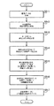
図1は、本発明の第1の実施例の模式的なブロック図である。本実施例によれば、デジタルカメラ1は、光源3によって照らされた患者2の画像を得るように構成された従来のデジタルカメラからなる。デジタルカメラ1によって得られた画像は、次に、ディスク5から供給され又は通信ネットワークを介して電気信号を受信することによるソフトウェアによって、コンピュータ4を、デジタルカメラ1から受信した画像データを処理し、ディスプレイ31に表示される出力画像を生成するようにする、多数の機能モジュール16−24によって構成されるコンピュータ4に送信される。 First Embodiment FIG. 1 is a schematic block diagram of a first embodiment of the present invention. According to this embodiment, the digital camera 1 comprises a conventional digital camera configured to obtain an image of the patient 2 illuminated by the
頬に美容上の傷32を有する患者が示されている本実施例において、出力画像30は、デジタルカメラ1によって生成された原画像を表す第1の画像部分33、及び患者2に治療を施すことによって予想される結果を表す、数値計算によって得られる患者2の画像を示す第2の画像部分34である。 In this embodiment, where a patient having a
光と皮膚との相互作用
コンピュータ4の種々の機能モジュール10〜24の詳細な処理について記載する前に、図2を参照して、皮膚の生理学的な構造、及び皮膚と光との相互作用について簡単に説明する。 Light and Skin Interaction Before describing the detailed processing of the various functional modules 10-24 of the
図2に示すように、皮膚は、外側の角質層50、表皮52、及び、皮膚のための毛細血管55を有する乳頭層54と網状層56とに分類される真皮からなる、層構造を有する。 As shown in FIG. 2, the skin has a layered structure consisting of an outer stratum corneum 50, an epidermis 52, and a dermis classified into a
光が皮膚に入射し、外側の角質層50に当たったとき、殆どの光は直ちに反射される。しかしながら、一部の入射光は、角質層50を通過して進んで行き、表皮52の構成要素及び乳頭層54と相互作用する。光が表皮52と乳頭層54を進むにつれて、光は皮膚内に存在する、乳頭層内の毛細血管55内の血液中に存在するヘモグロビン、メラニン、表皮52内のメラニン細胞57によって生成された色素、及び皮膚全体に存在する繊維状の物質であるコラーゲン等を主とする、種々の発色団によって吸収される。入射光が網状層56に達する頃には、光の散乱は高い割合で前方散乱になり、それゆえ網状層56は、事実上光を反射しないと考えられる。 When light enters the skin and strikes the outer stratum corneum 50, most of the light is immediately reflected. However, some incident light travels through the stratum corneum 50 and interacts with the components of the epidermis 52 and the
表皮52及び乳頭層54中に存在し種々の波長を吸収する発色団に加え、皮膚内の主にコラーゲンからなる所定の構造は、入射光を反射させる。それゆえ、皮膚の外観は、角質層50によって直ちに反射された光と、表皮52及び乳頭層54内に存在する発色団と相互作用して再放出された光とが混ざったものと考えられる。引用することによって取り込まれた、出願人の先の米国特許US6324417、及び米国への同時継続中の出願US09/760387、US10/240071、US10/521639、及びUS10/532158に示されるように、皮膚から再放出される光を処理して、皮膚内に存在する種々の発色団を測定することができる。 In addition to the chromophores present in the epidermis 52 and the
乳頭層54及び表皮52内の発色団の密度と分布を測定するために、表皮52及び乳頭層54内に存在する発色団と相互作用して再放出された光を測定できるように、角質層50によって直接反射される光の効果は取り除かれるべきである。 In order to measure the density and distribution of the chromophores in the
図1に戻って、本実施例では、第1の偏光フィルタ36がデジタルカメラ1のレンズの前に配置され、第2の偏光フィルタ38が光源3の前に交差偏光となるように配置される。これらのフィルタを設けることによって、皮膚内で光とコラーゲンとの相互作用が、光が偏光を失うようになされるためである。皮膚の他の層と相互作用することなく角質層50によって直接反射され、第2の偏光フィルタ38を通過する光は、第1の偏光フィルタ36によって除去される。それゆえ、デジタルカメラ1によって取得された画像データは、患者の皮膚の表皮52と乳頭層54の構造と相互作用して再放出された光だけを表すものである。 Returning to FIG. 1, in this embodiment, the first
先に言及したように、ディスク5に供給されたソフトウェア又は通信ネットワークを介した電気信号6としてのソフトウェアは、コンピュータ4の記憶手段とプロセッサーを多数の機能モジュールで構成されたようにする。 As mentioned above, the software supplied to the
図1に示す機能モジュールは、特許請求の範囲に記載された発明の働きを理解することを補助するための純粋に概念的なものであり、所定の実施例においてはソフトウェア用のソースコード中のコードのブロックに直接対応しないこともある。他の実施例においては、図示された機能モジュールによって遂行される機能は、異なるモジュール間で分割されるのでもよく、また、複数の異なる機能が同一のモジュールを再使用して遂行されるのでもよい。 The functional modules shown in FIG. 1 are purely conceptual to assist in understanding the operation of the claimed invention, and in certain embodiments, in the source code for software. It may not correspond directly to a block of code. In other embodiments, the functions performed by the illustrated functional modules may be divided between different modules, or multiple different functions may be performed by reusing the same module. Good.
本実施例では、機能モジュールは、RGB画像データを対応する球面座標系に変換する球面変換ユニット10、画像変換モジュール12、及び球面角度座標系で画像処理して血液密度とメラニン密度を示すデータを生成するための変換テーブル14、並びに、変換モジュール12によって生成された発色団の分布を処理して、治療を表す改訂された発色団の分布を決定するように構成された治療シミュレーションモジュール16、発色団の分布データを用いて画像データを生成する画像生成モジュール18と逆変換テーブル20、発色団の密度のばらつきのために現れていない、患者の画像中の容貌におけるばらつきを特定する組織決定モジュール22、及び、組織決定モジュール22によって生成された組織データと画像生成モジュール18によって生成された画像データとを結合し、ディスプレイの画面31上に表示するためのシミュレーションした治療画像34を出力するコンビネーションモジュール24、を備える。 In the present embodiment, the functional module performs image processing with the
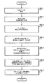
得られた画像データの処理
図1に示すコンピュータ4によって行われる処理のフローチャートである図3によれば、まず、光源3によって照らされた患者2の画像が、デジタルカメラ1で取得される(S3−1)。本実施例では、デジタルカメラ1は、通常のデジタルカメラによって構成される。デジタルカメラ1によって生成された画像は、それゆえ、画素の大配列に対して0〜255の値をとるRGB値からなり、RGB値は、画像内の各画素に対して、カメラ1内の受光器によって受光された光量を示し、完全に黒の画素が(0、0、0)のRGB値を有し、完全に明るい白の画素が(255、255、255)のRGB値を有するように、赤、緑、及び青を表す。 Processing of Obtained Image Data According to FIG. 3 which is a flowchart of processing performed by the
患者2の画像がカメラ1で取得されたとき、画像は、まず、画像内の各画素に対する従来のRGBデータを、球面角度θ、ψが実質的にデジタルカメラ1で撮像された画像内の個々の画素によって表される色相及び色度を示し、動径座標rが実質的に画素の明度を示す、球面座標系θ、ψ、rの対応するセットに変換する(S3−2)、球面変換モジュール10に送られる。 When the image of the patient 2 is acquired by the camera 1, the image is first converted from the conventional RGB data for each pixel in the image, and the spherical angles θ and ψ are substantially individually captured in the image captured by the digital camera 1. (S3-2), transforming into a corresponding set of spherical coordinate systems θ, ψ, and r, indicating the hue and chromaticity represented by the pixel of (3) and the radial coordinate r substantially indicating the brightness of the pixel. Sent to
この変換は、以下の式を用いて従来の方法で達成される。

次に、動径方向要素rの配列が直接画像生成モジュール18に送られるのに対し、球面角度座標θ、ψの計算値の配列は、本実施例では画像変換モジュール12に送られる。 Next, the array of radial direction elements r is directly sent to the
球面変換モジュール10が画像についてのRGB値を球面座標に変換した後、画像変換モジュール12は、次に、生成したθ、ψ値の配列を処理して、患者の皮膚の表面上の個々の点における血液密度及びメラニン密度を示す値を取得する。 After
本実施例では、これは、θ、ψ値がπ〜−π及び0〜π/2の値をとる代わりに、スケールされたθ、ψ値が0〜255の値をとる整数値からなるように、配列内の各画素に対して、θ、ψ値を順番にスケールする各θ、ψ値の対の処理によって達成される。次に、これらのスケールされたθ、ψ値は、本実施の形態においては、スケールされたθ、ψ座標の対を、このようなスケールされたθ、ψ値を与える血液とメラニンの密度に対応させる、255x255のルックアップテーブルである、変換テーブル14にアクセスするときに用いられる。本実施例では、変換テーブル14は、血液密度とメラニン密度を種々のθ、ψ値に対応させるテーブルからなり、θ、ψ値は、皮膚に対する色空間の予想された範囲内の値をとる。特定の画素に対するθ、ψ値の組み合わせが、発色団の密度のデータが変換テーブル14内に保存されている、範囲の値からはみ出す場合、本実施例では、変換モジュール12は、この画素に対して、そのθ、ψ値を有する画素の血液密度とメラニン密度として0を返す。 In the present example, this is made up of integer values where the scaled θ, ψ values take values from 0 to 255, instead of θ, ψ values taking values from π to -π and 0 to π / 2. In addition, for each pixel in the array, this is achieved by processing each θ, ψ value pair that sequentially scales the θ, ψ values. Next, these scaled θ and ψ values are converted into the density of blood and melanin that gives the scaled θ and ψ values, in this embodiment, to a pair of scaled θ and ψ coordinates. It is used when accessing the conversion table 14, which is a 255 × 255 lookup table. In this embodiment, the conversion table 14 is a table that associates blood density and melanin density with various θ and ψ values, and the θ and ψ values take values within the expected range of the color space for the skin. If the combination of θ and ψ values for a particular pixel is out of the range value for which the chromophore density data is stored in the conversion table 14, in this embodiment, the conversion module 12 Then, 0 is returned as the blood density and melanin density of the pixel having the θ and ψ values.
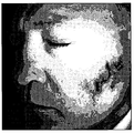
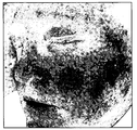
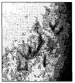
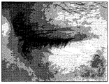
例えば図4A、図4B、及び図4Cを参照するが、図4Aは、デジタルカメラ1によって撮像された患者の顔の画像を示す例である。画像内の画素は、それぞれ、赤、緑、及び青の画素値からなる。図4B及び図4Cは、それぞれ、図4Aの例示的な画像を処理して導出され、決定された血液密度とメラニン密度を表すものであり、血液密度とメラニン密度のより高いものが画像内により黒い点で示されている。 For example, referring to FIGS. 4A, 4B, and 4C, FIG. 4A is an example showing an image of a patient's face imaged by the digital camera 1. FIG. Each pixel in the image consists of red, green and blue pixel values. 4B and 4C are derived from processing the exemplary image of FIG. 4A, respectively, and represent the determined blood density and melanin density, with higher blood density and melanin density being more visible in the image. Indicated by black dots.
出願人は、皮膚からの光の再放出を解析して、偏光した白色光の制御された照射下で、皮膚によって再放出された光が定義された色空間内にあることを正しく評価した。この色空間内で、皮膚のある部分に現れる色相又は色は、主に、血液密度及びメラニン密度の変動によって説明される。換言すれば、皮膚の特定の部分の明度は、主に、皮膚への入射光の明度、皮膚の特定の部分を照らす光の角度、対象物と光源との距離、及び、コラーゲンの密度によって多かれ少なかれ反射が起こることによる特定の点のコラーゲン密度、の組み合わせによって決定される。 Applicants analyzed the re-emission of light from the skin and correctly evaluated that the light re-emitted by the skin was within a defined color space under controlled illumination of polarized white light. Within this color space, the hues or colors that appear in certain parts of the skin are mainly explained by fluctuations in blood density and melanin density. In other words, the brightness of a specific part of the skin is largely dependent on the brightness of the light incident on the skin, the angle of the light that illuminates the specific part of the skin, the distance between the object and the light source, and the density of the collagen. It is determined by the combination of the collagen density at a particular point due to the more or less reflection.
本解析によって、出願人は、さらに、照明光の強さ、距離、及び角度が制御されない非制御の照明条件の下で、照明の強さ、距離、及び角度の変動は、皮膚の外見上の明るさに重大な変動を起こすが、皮膚の外見上の色又は色相には限定的な影響しか及ぼさないことを、正しく評価した。それゆえ、デジタル画像内の画素に対するRGB値が球面座標系の変換されたとき、照明とコラーゲン密度の変動による明度の変化は、特定の画素に対して、主に動径r値の変化によって説明される。これに対して、RGB画像を球面座標系に変換して得られた角度値θ、ψは、主に、血液密度及びメラニン密度の変動によって決定され、実質的に光の配置に影響されない。出願人は、それゆえ、血液密度及びメラニン密度の測定が角度値のみを処理して決定され、それによって、カメラ1で撮像された画像から、そのような密度の測定値を導出するために必要とされるデータ量を減らすことができることを、正当に評価した。 With this analysis, Applicant further allows for variations in illumination intensity, distance, and angle to be apparent in the skin under uncontrolled lighting conditions where the intensity, distance, and angle of the illumination light are not controlled. It was correctly evaluated that it caused significant variations in brightness, but had a limited effect on the apparent color or hue of the skin. Therefore, when RGB values for pixels in a digital image are transformed in a spherical coordinate system, the change in brightness due to variations in illumination and collagen density is explained mainly by changes in the radial r value for a particular pixel. Is done. On the other hand, the angle values θ and ψ obtained by converting the RGB image into the spherical coordinate system are mainly determined by fluctuations in blood density and melanin density, and are not substantially affected by the light arrangement. Applicant therefore determines that blood density and melanin density measurements are determined by processing only the angle values, thereby deriving such density measurements from the image taken with camera 1. We justified that we can reduce the amount of data.
図3に戻って、画像内の各画素についての血液及びメラニンの発色団の分布値が、変換モジュール12によって計算された後、この発色団分布データは、変換モジュール12によって、治療シミュレーションモジュール16と画像生成モジュール18に出力される。発色団の分布値が治療シミュレーションモジュール16によって受信されたとき、治療シミュレーションモジュール16は、受信した発色団の分布値を処理して、治療後の発色団の分布を示す、改訂された発色団の分布値を生成する(S3−4)。 Returning to FIG. 3, after the blood and melanin chromophore distribution values for each pixel in the image are calculated by the conversion module 12, the chromophore distribution data is converted by the conversion module 12 to the
図4Aの画像内に見える患者の場合を例にとると、患者は、図4Aの画像の左側に示された彼らの頬の上に多数の細絡を有する。これらの細絡は、図5Aの拡大された画像内において、よりはっきりと観測されることがあり、図5Bとして示された図4Bの拡大された画像部分に対応している。 Taking the case of a patient visible in the image of FIG. 4A as an example, the patient has a number of fine lines on their cheeks shown on the left side of the image of FIG. 4A. These fine lines may be more clearly observed in the magnified image of FIG. 5A and correspond to the magnified image portion of FIG. 4B shown as FIG. 5B.
そのような細絡は、皮膚の表面付近に過剰に大きい血管が存在するために生ずる。これらの細絡は、望まない血管のカテーテル療法によって治療できる。患者にこのような治療の結果を見せるため、本実施例において、治療シミュレーションモジュール16は、血液の密度を表す受信された発色団の分布を処理し、治療後の血液の期待される分布である改訂された血液分布のデータを生成する。 Such fines are caused by the presence of excessively large blood vessels near the surface of the skin. These fines can be treated by unwanted vascular catheterization. In order to show the results of such treatment to the patient, in this embodiment, the
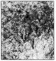
細絡の出現を除くように画像を処理する例である本実施例において、改訂された血液の分布データは、治療がなされる画像部分をくすませる従来のアルゴリズムを応用して決定される。 In the present embodiment, which is an example of processing an image so as to eliminate the appearance of fine lines, the revised blood distribution data is determined by applying a conventional algorithm that obscures the portion of the image to be treated.
そのようなくすみのアルゴリズムを用いた図4Bの画像の処理の結果が、図4Dとして示されている。図5B内のハイライトが当てられた、これらの特定の画像領域を処理した結果が図5Cとして示されている。図4Bと図4Dとを、図5Bと図5Cとを比較することによって分かるように、治療シミュレーションモジュール16による処理の結果は、本実施例において、患者に対して、血液が計算された原の分布において存在するものよりもよりスムーズに分布する、血液分布を示す血液分布データを生成することである。 The result of processing the image of FIG. 4B using such a dull algorithm is shown in FIG. 4D. The result of processing these specific image areas, highlighted in FIG. 5B, is shown as FIG. 5C. As can be seen by comparing FIG. 4B and FIG. 4D and FIG. 5B and FIG. It is to generate blood distribution data indicating a blood distribution that is distributed more smoothly than existing in the distribution.
図3に戻って、治療シミュレーションモジュール16への発色団の分布データの出力に加え、変換モジュール12は、また、発色団の分布データを、発色団の異なる分布のために見えない患者の容貌における変動を示す、組織のデータを、逆変換テーブル20及び組織決定モジュール22と伴って決定するように処理を進める、画像生成モジュール18にも出力する(S3−5)。 Returning to FIG. 3, in addition to outputting the chromophore distribution data to the
さらに、先に説明したように、患者の皮膚のくっきりと明るい部分の主たる変動は、コラーゲンの密度と照明とにおける変動によって見え、一方、患者の皮膚の色相がくっきりとしている部分は、主に、血液及びメラニンからなる発色団の分布及び密度の変動によって見える。しかしながら、その他の因子も本当は、患者の容貌に影響する。典型的には、そのような因子は、狭い範囲の皮膚の組織によって見える変動を含む。しかしながら、以下に説明されるように、他の因子によって見える容貌におけるこれらの変動を特定することは、可能である。 Furthermore, as explained above, the main fluctuations in the sharp and bright parts of the patient's skin are seen by fluctuations in collagen density and illumination, while the parts where the patient's skin hue is clear are mainly Visible by fluctuations in the distribution and density of chromophores consisting of blood and melanin. However, other factors also really affect the patient's appearance. Typically, such factors include variations that are visible by a narrow range of skin tissue. However, as explained below, it is possible to identify these variations in appearance seen by other factors.
本実施例では、画像生成モジュール18は、まず、画像内の各画素について修正されていない発色団の分布データを処理し、対応するθ、ψの色角度の期待値の対を生成する。本実施例では、この変換は、画素についての血液及びメラニンの決定された密度の各可能な対を、対応するθ、ψの期待値に対応させるルックアップテーブルである、逆変換テーブル20にアクセスする画像生成モジュール18によって達成される。それゆえ、逆変換テーブル20は、変換テーブル14に格納されているようにθ、ψ値を血液密度及びメラニン密度の測定値に変換する関数、に対応する逆関数を表すデータである。発色団の分布データ内の0値に対応させられる画素の場合、θ、ψ値は決定されない。 In this embodiment, the
発色団の分布データをこのように処理すること、及び、球面変換モジュール10によって生成された、画素に対する動径座標rにアクセスすることによって、画像生成モジュール18は、変換モジュール12が発色団の分布値を決定することのできる各画素値が、球面変換モジュール10によって決定されるように、色角度θ、ψの計算値の対とその特定の画素の動径値に対応する動径値rとによって表される、導出画像を生成することができる。 By processing the chromophore distribution data in this way and accessing the radial coordinates r for the pixels generated by the
次に、この導出画像データは、受け取ったθ、ψ、rデータの並びを等価なRGB値画像に変換するように処理を進める組織決定モジュール22に出力される。 Next, the derived image data is output to the tissue determination module 22 that proceeds to process the sequence of the received θ, ψ, and r data into an equivalent RGB value image.
これは、各画素のθ、ψ、rデータに次の式を適用して達成される。
次に、組織決定モジュール22は、各画素に対して、その画素に対する計算されたRGB値と、デジタルカメラ1によって取得された原の画像データ内の対応するRGB値との差をとる処理を行う。 Next, the tissue determination module 22 performs processing for each pixel to obtain a difference between the RGB value calculated for the pixel and the corresponding RGB value in the original image data acquired by the digital camera 1. .
変換モジュール12によって発色団データが生成されない画素の場合、この差のデータは、原画像内の対応する画素に対するRGB値に対応する。ここで、変換モジュール12が特定の画素に対して発色団の分布データを導出することができ、もし、導出されたRGB値が原画像内のその画素に対するRGB値に正確に対応しないとき、これは、その画素によって表される皮膚の領域の何らかの明確な発色が、皮膚のその領域に対する血液及びメラニンの推定された密度以外の要因によって見えることを意味する。次に、RGB値の差の並びは、コンビネーションモジュール24に出力される組織データとして出力される。 In the case of pixels for which chromophore data is not generated by the conversion module 12, this difference data corresponds to the RGB values for the corresponding pixels in the original image. Here, the conversion module 12 can derive chromophore distribution data for a particular pixel, and if the derived RGB value does not exactly correspond to the RGB value for that pixel in the original image, this Means that any distinct color development of the area of skin represented by that pixel is visible due to factors other than the estimated density of blood and melanin for that area of skin. Next, the array of RGB value differences is output as tissue data output to the
変換モジュール12によって出力された発色団の原の分布データと球面変換モジュール10によって出力された動径データの処理に加え、本実施例では、画像生成モジュール18は、また、治療シミュレーションモジュール16によって生成された発色団の改訂された分布を、個々の画素に対する動径値rと共に、治療シミュレーションモジュール16によって決定された発色団の分布における変化となる治療の後の、特定の部分の皮膚の容貌、を示すθ、ψ値を生成する方法と同様に、処理するようにも構成される(S3−6)。 In addition to processing the original distribution data of the chromophore output by the conversion module 12 and the radial data output by the
発色団の原の分布データの処理の場合のように、これは、逆変換テーブル20にアクセスし、個々の画素に対して、決定された血液密度とメラニン密度をθ、ψ値に変換する画像生成モジュール18によって、達成される。次に、得られたθ、ψ値は、画素について決定された球面座標系の元の動径要素rと共に、上記の従来の方法で処理され、得られたθ、ψ、r値がその画素によって表される患部に対する赤、緑、青のチャンネルの強度を表す、その画素に対する従来のRGB値に変換される。この処理は、発色団の分布が変換モジュール12によって決定された、全ての画素に対して繰り返される。次に、生成された赤、緑、及び青の画値は、画像生成モジュール18によって、治療画像として、コンビネーションモジュール24に出力される。 As in the case of processing the original distribution data of the chromophore, this accesses the inverse conversion table 20 and converts the determined blood density and melanin density into θ and ψ values for each pixel. This is accomplished by the
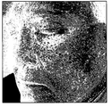
それゆえ、図4Dの修正された血液の画像、図4Cのメラニンの画像、及び図4Aの画像を処理して決定された動径座標値を例にとると、細絡の原因の血管が、図4Dに示す血液分布となるように治療された、図4Aの画像内に見える患者の容貌を示す治療画像が生成され、図4Eのように示される。 Therefore, taking the modified blood image of FIG. 4D, the melanin image of FIG. 4C, and the radial coordinate values determined by processing the image of FIG. A therapeutic image showing the patient's appearance visible in the image of FIG. 4A, treated to the blood distribution shown in FIG. 4D, is generated and shown in FIG. 4E.
図に見えるように、処理の結果は、細絡によって見える異常が取り除かれているところ以外は、原の画像のものと同様の画像が生成される。この違いは、図5Aにハイライトされた原の画像部分に対応する画像部分を、図5Dに示され、図4Eからのハイライトされた対応する画像部分と比較することによって、最も明確に見えるであろう。 As can be seen in the figure, the result of the process is an image similar to that of the original image except that the anomaly that is visible due to the fine line is removed. This difference is most clearly seen by comparing the image portion corresponding to the original image portion highlighted in FIG. 5A with the corresponding image portion highlighted in FIG. 5D and from FIG. 4E. Will.
上述したように、球面座標系から発色団の分布への変換、及びそのような発色団の分布から角度座標系への再変換は、特定画像部分の色相の全ての変化が発色団の密度の変化によるという仮定に基礎を置くため、画像生成モジュール18によって生成された治療画像は、他の因子によって見える特徴が欠けているであろう。 As described above, conversion from a spherical coordinate system to a chromophore distribution, and re-transformation from such a chromophore distribution to an angular coordinate system, all changes in hue of a particular image portion are related to the chromophore density. Based on the assumption of change, the therapeutic image generated by the
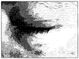
それゆえ、例えば、図4Aと図4Eとを、また図5Aと図5Dとを比較すると、図4E及び図5Dの生成された画像は、対応する図4A及び図5Aの原の画像と比較したとき、組織が欠けて見える。これは、画像内に見える患者の目に対応する画像部分内に、最も明確に見てとれる。 Thus, for example, comparing FIGS. 4A and 4E and FIGS. 5A and 5D, the generated images of FIGS. 4E and 5D were compared with the corresponding original images of FIGS. 4A and 5A. When the organization appears to be lacking. This is most clearly seen in the image portion corresponding to the patient's eyes visible in the image.
これらの差異を示すために、患者の目の部分に対応する、図4Aの原の画像内の部分が図6Aに示され、図4Eの生成された画像からの対応する部分が図6Bとして示される。目の部分の周りの2つのこれらの画像内に処理の結果として最もくっきりと見てとれるように、目の周りの細かい線状組織の大部分はなくなっている。 To illustrate these differences, the portion in the original image of FIG. 4A corresponding to the portion of the patient's eye is shown in FIG. 6A and the corresponding portion from the generated image of FIG. 4E is shown in FIG. 6B. It is. Most of the fine linear tissue around the eye is gone, as can be seen most clearly as a result of the processing in the two images around the eye.
球面座標系についての変換と逆変換によって失われた詳細構造は、治療画像の生成に用いた発色団分布のいかなる取り扱いにも無関係なので、この失われた組織の情報は、本実施例では、まさに画像に対して組織決定モジュール22によって決定された組織のデータである。 Since the detailed structure lost due to the transformation and inverse transformation for the spherical coordinate system is irrelevant to any treatment of the chromophore distribution used to generate the treatment image, this lost tissue information is exactly the same in this example. This is the tissue data determined by the tissue determination module 22 for the image.
それゆえ、本実施例では、この失われた情報は、コンビネーションモジュール24によって、治療画像内の各画素の赤、緑、及び青の値を、組織決定モジュール22によって決定されたこれらの画素に対して決定された、対応する赤、緑、及び青の値に変えることよって、画像に戻されうる。本実施例において、この処理は、見えなくなった組織を戻すことに加え、画像変換モジュール12が球面座標θ、ψを発色団の密度に変換できなかった画素もまた、デジタルカメラ1によって得られた原の画像からのこれらの画素に対する原の画素値によって表されるようにする。 Therefore, in this embodiment, this lost information is used by the
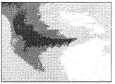
この組織を図4Eの治療画像に戻した後に生成された最終画像は、図4Fに示される。図5D及び図6Bに示された部分に対応する、最終画像のハイライトが当てられた部分は、また、それぞれ図5E及び図6Cとして図示されている。 The final image generated after returning this tissue to the treatment image of FIG. 4E is shown in FIG. 4F. The highlighted portions of the final image corresponding to the portions shown in FIGS. 5D and 6B are also illustrated as FIGS. 5E and 6C, respectively.
特に、図6Cから見てとれるように、組織決定モジュールによって導出された組織データを付加することは、画像に、図6Aの原の画像と比較したときに、図6Bの生成された画像には見えない詳細な組織を、戻している。 In particular, as can be seen from FIG. 6C, adding the tissue data derived by the tissue determination module will result in the image generated in FIG. 6B when compared to the original image in FIG. 6A. The detailed organization which cannot be seen is returned.
次に、カメラによって生成された原の画像33と最終的に生成された画像34は、出力され、出力画像30としてディスプレイ31上に同時に表示されることができ、もって、患者に治療の期待される結果を示すことができる。 Next, the
第2の実施例
以下、本発明の第2の実施例は、それぞれが、本発明の第2の実施例の画像処理システムの模式的なブロック図と画像処理システムによって行われる処理のフローチャートである、図7及び図8を参照して、記載される。 Second Embodiment Hereinafter, each of the second embodiments of the present invention is a schematic block diagram of an image processing system of the second embodiment of the present invention and a flowchart of processing performed by the image processing system. , Will be described with reference to FIGS.
第1の実施例では、画像処理システムは、画像生成モジュール18が、発色団の分布データと球面変換モジュール10によって導出された動径rデータを用いて、導出画像と治療画像を生成するものとして記載された。次に、導出画像のデータは組織決定モジュール22によって処理され、出力画像を生成するために、生成された治療画像のデータとコンビネーションモジュール24によって次に結合される、組織のデータが得られた。 In the first embodiment, in the image processing system, the
本実施例では、画像に対して球面変換モジュール10によって決定されたr座標を用いることなく、導出画像のデータと治療画像のデータから直接出力画像を生成する、他の画像処理システムが記載される。 In this embodiment, another image processing system is described that generates an output image directly from derived image data and treatment image data without using r coordinates determined by the
図7に示すように、本発明の本実施例の画像処理システムは、組織決定モジュール22とコンビネーションモジュール24が出力モジュール100によって置き換えられ、画像生成モジュール18と逆変換テーブル20が修正画像生成モジュール101と修正逆変換テーブル102に置き換えられていることを除けば、先の実施例の画像処理システムと同一である。システムの残りの要素は、先に第1の実施例と関連して記載された要素と同一であり、先に図1において使用されたものと同一の参照番号によって特定される。 As shown in FIG. 7, in the image processing system of this embodiment of the present invention, the tissue determination module 22 and the
図7の画像処理システムによって実行される処理は、図8のフローチャートによって図示される。入力画像のデータから発色団の分布データを導出し、その発色団の分布データを用いて模擬された治療データを導出する、システムによる処理(s8−1〜s8−4)は、第1の実施例において確保された対応するステップ(s3−1〜s3−4)と同一であり、これらのステップについての記載は繰り返されない。 The processing executed by the image processing system of FIG. 7 is illustrated by the flowchart of FIG. The system processing (s8-1 to s8-4) for deriving chromophore distribution data from input image data and deriving treatment data simulated using the chromophore distribution data is the first implementation. It is the same as the corresponding steps (s3-1 to s3-4) reserved in the example, and the description of these steps will not be repeated.
図7の画像処理システムが発色団の分布データと模擬された治療データを導出した後、このデータは、次に、画像生成モジュール101によって処理される(s8−5)。 After the image processing system of FIG. 7 has derived chromophore distribution data and simulated treatment data, this data is then processed by the image generation module 101 (s8-5).
特に、本実施例では、画像処理モジュール101が、導出された発色団の分布データと模擬された治療データとを、本実施例において、血液密度とメラニン密度の対を、固定された照明条件の下で見えるそのような血液密度とメラニン密度を有する皮膚の外見上の色を表すRGB値に、対応させるルックアップテーブルからなる、修正された逆変換テーブル102にアクセスして処理する。 In particular, in this embodiment, the
修正された逆変換テーブル102に格納されたRGB値は、固定された照明条件の下で見える、血液密度比及びメラニン密度比を含む、皮膚の外見の経験データを格納することによって生成されるのでもよい。しかしながら、本実施例においては、RGB値は、血液密度及びメラニン密度を、変換テーブル14内のデータによって定義されているような球面座標θ、ψに関連付ける逆関数を適用し、決定された球面座標θ、ψをrを固定してRGB値に変換することによって決定されたRGBの計算値からなる。 The RGB values stored in the modified inverse transformation table 102 are generated by storing empirical data of skin appearance, including blood density ratio and melanin density ratio, which are visible under fixed lighting conditions. But you can. However, in this embodiment, the RGB values are determined by applying an inverse function that associates the blood density and melanin density with the spherical coordinates θ, ψ as defined by the data in the conversion table 14 to determine the spherical coordinates. It consists of RGB calculated values determined by converting θ and ψ to RGB values with r fixed.
先の実施例におけるように、画像生成モジュール101は、発色団の分布と改訂された発色団の分布における、発色団の密度値の各対を、順次処理する。画像処理モジュール101によって実行され、発色団の分布を定義する配列の処理の結果として、画像生成モジュール101は、1対のRGB画像を生成する。次に、これらの画像は出力モジュール100に出力される。 As in the previous embodiment, the
先に記載したように、RGB画像データが球面座標データに変換されるとき、角度座標θ、ψは、皮膚内に血液、メラニン等の発色団が存在すること及びその密度により見える、個々の画素によって表される色相及び色度を実質的に示す。そして、動径座標rは、実質的に、照明の要因と皮膚内のコラーゲンの密度とを組み合わせることによって生ずる、画素の明度を示す。本実施例において、導出画像及び治療画像内の画素に対するRGB値は一定のr値を用いて生成されるため、画像は、固定された照明条件の下の、コラーゲンの密度が一定の、皮膚の領域を表すであろう。 As described above, when RGB image data is converted into spherical coordinate data, the angle coordinates θ and ψ are the individual pixels that are visible due to the presence of chromophores such as blood and melanin in the skin and their density. The hue and chromaticity represented by are substantially shown. The radial coordinate r substantially indicates the brightness of the pixel that is generated by combining the factor of illumination and the density of collagen in the skin. In this example, the RGB values for the pixels in the derived image and the treatment image are generated using a constant r value, so that the image has a constant collagen density under fixed illumination conditions. Will represent the region.
実際の照明条件下の患者及び変動するコラーゲンの量を表す画像を生成するため、画像内の各画素に対するRGBの出力値は、以下の式を用いて導出される(s8−6)。
ここで、Rout(x、y)、Gout(x、y)、及びBout(x、y)は座標x、yでの画素に対するRGBの出力値であり、Roriginal(x、y)、Rderi ved(x、y)、Rtreated(x、y)、Goriginal(x、y)、Gd erived(x、y)、Gtreated(x、y)、Boriginal(x、y)、Bderived(x、y)、Btreated(x、y)は、それぞれ、デジタルカメラ1によって取得された原の画像、画像生成モジュール101によって生成された、導出画像及び治療画像、内における座標x、yでの対応する画素に対する赤、緑及び青の値である。Here, R out (x, y), G out (x, y), and B out (x, y) are RGB output values for the pixel at coordinates x, y, and R original (x, y) , R deri ved (x, y ), R treated (x, y), G original (x, y), G d erived (x, y), G treated (x, y), B original (x, y) , B derived (x, y) and B treated (x, y) are the coordinates in the original image acquired by the digital camera 1, the derived image and the treatment image generated by the
各画素における各色のチャネルに対して、カメラ1によって出力された原の画像内の色の値と、生成された導出画像内の対応する色の値との比を決定し、次に、治療画像内における対応する色の値をこの比よってスケーリングすることによって、照明及び原の画像内に存在するコラーゲンの変動による見掛け上の明度の変動を反映させ、もって、実際的な最終出力画像を生成するように、各画素の明度を変化させる手段が提供される。最後に、生成された出力画像が出力され(s8−7)、表示画面31上に表示される。 For each color channel at each pixel, the ratio of the color value in the original image output by the camera 1 to the corresponding color value in the generated derived image is determined, and then the treatment image By scaling the corresponding color value in this by this ratio, it reflects the variation in lightness due to illumination and the variation of collagen present in the original image, thus producing a practical final output image Thus, a means for changing the brightness of each pixel is provided. Finally, the generated output image is output (s8-7) and displayed on the
第3の実施例
以下、本発明の第3の実施例が、図9A及び図9Bを参照して、簡潔に記載される。 Third Embodiment Hereinafter, a third embodiment of the present invention will be briefly described with reference to FIGS. 9A and 9B.
第1及び第2の実施例では、細絡の治療の効果を模擬する画像を生成するシステムについて記載されたが、記載されたシステムが患者の皮膚内の発色団の分布を変える美容上又は外科上の治療を模擬するように修正されるのでもよいことが、適切に認識されるであろう。それゆえ、例えば、他の実施例においては、改訂されたメラニンの分布に基づいて生成された画像が、生成されるのでもよい。このようなシステムは、例えば、加齢斑の出現に関しての、酸を使用した剥皮の効果を模擬するのでもよい。 In the first and second embodiments, a system has been described that generates an image that mimics the effect of a fine-line treatment, but the described system changes the distribution of chromophores within the patient's skin, either cosmetically or surgically. It will be appreciated that it may be modified to simulate the above treatment. Thus, for example, in other embodiments, an image generated based on the revised melanin distribution may be generated. Such a system may, for example, simulate the effect of peeling using acid on the appearance of age spots.
代わりに、本発明は、軽い疾患又は老化の進行の効果を示すことに、用いることができる。そのような実施例において、第1及び第2の実施例の治療シミュレーションモジュール16は、画像変換モジュール12によって生成されて得られた発色団分布を処理して、改訂された発色団分布が軽い疾患又は加齢によって生ずる分布を表す、改訂された発色団分布を生成するように変更される。 Instead, the present invention can be used to show the effect of mild disease or progression of aging. In such an embodiment, the
それゆえ、例えば、図9A及び図9bを参照すると、図9Aは、患者の原の画像の一例である。図9Bは、患者の顔にできたざそうが図9Aの画像に対して決定された発色団の分布を処理することによって模擬される、本発明の第3の実施例によって生成された例示的な画像である。 Thus, for example, referring to FIGS. 9A and 9b, FIG. 9A is an example of an original image of a patient. FIG. 9B is an exemplary generated by the third embodiment of the present invention, in which the appearance on the patient's face is simulated by processing the chromophore distribution determined for the image of FIG. 9A. It is an image.
さらに他の実施例は、例えば、修正された発色団の分布を生成し、また、他の異常、又は、日焼け等の疾患の画像を生成することができる。 Still other embodiments can generate, for example, a modified chromophore distribution and images of other abnormalities or diseases such as sunburn.
他の実施例及び修正
上記の第1の実施例において、偏光した光によって照らされた画像が得られるシステムが記載された。クロス偏光フィルタ36を用いて画像を取得することによって、患者の皮膚の表面からの、直接的な鏡面反射が除去される。 Other Embodiments and Modifications In the first embodiment above, a system has been described in which an image illuminated by polarized light is obtained. By acquiring an image using the
他の実施例においては、鏡面反射が除去された患者の画像が得られることに加え、クロス偏光フィルタ36を外したときに、更なる画像が得られることが理解されるであろう。そして、クロス偏光フィルタ36を外したときに得られる画像は、導出画像と、偏光フィルタ36を外したときに得られる画像との差異を特定する組織データを生成するように、組織決定モジュール22によって処理されるのでもよい。この組織のデータが治療画像と組み合わされたとき、導出画像から失われた組織のみならず、皮膚の表面からの鏡面反射に由来する見え方の差異をも含む、最終出力画像が生成される。このようなシステムの利点は、コンピュータによって生成された画像が、直接反射が生成された画像中にも存在するため、より実際的であるということである。 It will be appreciated that in other embodiments, in addition to obtaining a patient image with the specular reflection removed, additional images are obtained when the
偏光フィルタ36を入れたときと外したときの両方で画像が得られるシステムにおいては、2つの画像が偏光フィルタ36を外して連続的に取得可能であり、又は、代わりに、クロス偏光フィルタ36を外したときの画像データを取得するための目的でのみ付加的なデジタルカメラが設けられることが、理解される。 In a system where images are obtained both with and without the
上記の実施例には、1種類の発色団の分布の処理を含むシステムが記載されてきた。他の実施例において、発色団についての修正された複数の発色団の分布が生成され、また、発色団についての改訂された複数の発色団の分布に基づいて生成された模擬画像が生成されうることが理解される。 The above example has described a system that includes processing a distribution of one type of chromophore. In other embodiments, a modified chromophore distribution for a chromophore can be generated, and a simulated image generated based on the revised chromophore distribution for a chromophore can be generated. It is understood.
上記の実施例では、血液密度及びメラニン密度が測定されるシステムが記載されてきたが、ビリルビン、刺青剤若しくは染色剤、ケラチン、及び体毛等の他の発色団を測定するように、システムが変更され得ることが理解される。このような他の実施例において、デジタルカメラによって検出される放出光の波長は、例えばメラニン等の存在によって実質的に影響されない波長を測定するように、選択されるのでもよい。記載されたようにそのような測定値を処理することは、他の発色団の測定値を得ることを可能にする。 While the above examples have described systems for measuring blood density and melanin density, the system has been modified to measure other chromophores such as bilirubin, tattoos or stains, keratin, and body hair. It is understood that it can be done. In such other embodiments, the wavelength of the emitted light detected by the digital camera may be selected to measure a wavelength that is substantially unaffected by the presence of, for example, melanin. Processing such measurements as described makes it possible to obtain measurements of other chromophores.
他に、デジタルカメラによって取得された画像内の、赤、緑、及び青のチャネルに対応する3種類の測定値を得る代わりに、より多くの波長帯に対する強度測定値を取得する修正されたカメラが設けられ、付加的な測定値が、例えば、血液、メラニン、コラーゲン等の密度の測定値を決定するために用いられるのでもよい。このようなシステムにおいては、通常の、赤、緑、及び青のチャネルに加え、赤外領域での測定値が得られるように構成されたデジタルカメラが、使用されるのでもよい。 Alternatively, a modified camera that obtains intensity measurements for more wavelength bands instead of obtaining three types of measurements corresponding to the red, green, and blue channels in an image acquired by a digital camera And additional measurements may be used to determine density measurements of blood, melanin, collagen, etc., for example. In such a system, a digital camera configured to obtain measurements in the infrared region in addition to the normal red, green and blue channels may be used.
他の実施例においては、画像変換モジュールによって生成された発色団の分布データを処理して発色団の異常な分布を識別する手段が、設けられるのでもよい。 In other embodiments, means for processing the chromophore distribution data generated by the image conversion module to identify anomalous chromophore distribution may be provided.
それゆえ、例えば細絡の場合、特定の体の部分に対して、異常に高い血液の密度が自動的に検出され、密度の期待値の平均値で置き換えられるのでもよい。他の実施例においては、異常に高い又は低い、他の発色団の密度が検出され修正されるのでもよい。上記の実施例では、メラニン密度の測定値を得ることについて記載されたが、異なる種類のメラニンの分布及び密度の測定値が提供される、実施例が構成可能であることが理解される。それゆえ、例えば、ある実施例では、メラニンの測定値が、メラニンの総量の測定値よりもむしろ、オイメラニンの分布の測定値のみ、又は、代わりにフェオメラニンの測定値のみからなるように、システムが構成されるのでもよい。 Thus, for example, in the case of a fine line, an abnormally high blood density may be automatically detected for a particular body part and replaced with an average of the expected density values. In other embodiments, other chromophore densities that are abnormally high or low may be detected and corrected. While the above example has been described for obtaining a measurement of melanin density, it is understood that the examples are configurable where measurements of distribution and density of different types of melanin are provided. Thus, for example, in one embodiment, the system is such that the measurement of melanin consists only of a measurement of the distribution of eumelanin, or instead of only a measurement of pheomelanin, rather than a measurement of the total amount of melanin. May be configured.
上記の実施例では、生成された画像データがスクリーンイメージとして出力されるように記載してきたが、もし画像内に見える患者の3Dコンピュータモデルが使用できる場合、生成された画像データは、モデルに現れる組織用の組織付与データとしてとして使用され、もって、改訂された発色団の分布を使用した患者の容貌の3Dモデルを生成することが可能であることが、理解される。 In the above example, it has been described that the generated image data is output as a screen image, but if a 3D computer model of the patient visible in the image is available, the generated image data appears in the model. It will be appreciated that it is possible to generate a 3D model of the patient's appearance using the revised chromophore distribution, as used as tissue loading data for the tissue.
図面を参照して記載された本発明の実施例は、コンピュータ及びコンピュータ内で実行される処理からなるが、本発明は、また、本発明を実施するコンピュータプログラム、特に、キャリア上の又はキャリア内のコンピュータプログラムに拡張される。プログラムは、ソースコード、オブジェクトコード、又は、本発明による工程の設定における使用に適したいかなる他の形態であってもよい。キャリアは、プログラムを持ち運べる、いかなる実体又はデバイスであってもよい。 The embodiment of the invention described with reference to the drawings consists of a computer and a process executed in the computer, but the invention also comprises a computer program implementing the invention, in particular on or in a carrier. Extended to computer programs. The program may be in source code, object code, or any other form suitable for use in setting up a process according to the present invention. The carrier may be any entity or device that can carry the program.
例えば、キャリアは、CD−ROM、半導体ROM等のROMからなる記憶メディア、又は、フロッピーディスク(登録商標)、ハードディスク等の磁気記録媒体からなるのでもよい。さらに、キャリアは、電気的なケーブル又は光学的なケーブルを介して電波又は他の手段で搬送される電気信号又は光学信号等の、伝播するキャリアであってもよい。 For example, the carrier may be formed of a storage medium such as a CD-ROM or a semiconductor ROM, or a magnetic recording medium such as a floppy disk (registered trademark) or a hard disk. Further, the carrier may be a propagating carrier such as an electrical or optical signal carried by radio waves or other means via electrical or optical cables.
プログラムがケーブル又は他の装置若しくは手段によって直接搬送される信号に実現されるとき、キャリアは、そのようなケーブル又は他の装置若しくは手段によって構成されるのでもよい。 When the program is implemented in a signal carried directly by a cable or other device or means, the carrier may be constituted by such a cable or other device or means.
代わりに、キャリアは、プログラムが埋め込まれ、関連する処理を遂行するように調節された、又は関連する処理の性能において使用される、集積回路によって構成されるのでもよい。 Alternatively, the carrier may be constituted by an integrated circuit in which the program is embedded and adjusted to perform the associated process or used in the associated process performance.
Claims (23)
前記データ格納手段(14、20)に格納されたモデルデータを用いて、患者の画像を表す、受信された画像データを処理し、表された前記患者の皮膚内の少なくとも1つの発色団の分布を決定する分布決定モジュール(12)と、
前記分布決定モジュール(12)によって決定された少なくとも1つの発色団分布の、決定された分布を処理して、改訂された発色団の分布を表すデータを生成する処理モジュール(16)と、
前記分布決定モジュール(12)によって決定された少なくとも1つの決定された発色団の分布と、患者の画像を表す受信された画像データとを使用し、表された患者の皮膚における、前記少なくとも1つの発色団の分布以外の要因による患者の皮膚の容貌における変動を決定する、変動決定モジュール(22)と、
前記プロセスモジュール(16)によって決定された改訂された発色団の分布を表すデータ、1つ以上の発色団の密度と前記1つ以上の発色団の前記密度を含む皮膚の外見上の色を示すデータとの前記関係を定義する前記格納されたデータ(14、20)、及び、前記変動決定モジュール(22)によって決定され、表された患者の皮膚内の前記少なくとも1つの発色団の分布以外の要因による前記患者の皮膚の容貌における変動を用いて、患者を表すデータを生成する画像データ生成モジュール(18、24)と、を備えることを特徴とする画像処理装置。Data storage means (14, 20) for storing model data defining the relationship between the density of the one or more chromophores and the data indicating the apparent color of the skin, including the density of the one or more chromophores. )When,
Using the model data stored in the data storage means (14, 20), the received image data representing the patient image is processed and the distribution of the represented at least one chromophore in the patient skin represented. A distribution determination module (12) for determining
A processing module (16) for processing the determined distribution of the at least one chromophore distribution determined by the distribution determination module (12) to generate data representative of the revised chromophore distribution;
Using the distribution of at least one determined chromophore determined by the distribution determination module (12) and the received image data representing a patient image, said at least one in the represented patient skin A variation determination module (22) for determining variations in the appearance of the patient's skin due to factors other than the distribution of chromophores;
Data representing the revised chromophore distribution determined by the process module (16), showing the apparent color of the skin including the density of one or more chromophores and the density of the one or more chromophores Other than the distribution of the at least one chromophore in the patient's skin determined and represented by the stored data (14, 20) defining the relationship with the data and the variation determination module (22) An image data generation module (18, 24) for generating data representing a patient using a variation in the appearance of the patient's skin due to a factor.
患者を偏光した光で照らす光源(3、38)と、
前記光源(3、38)によって生成された偏光した光を除去する、偏光フィルタ(36)と、を備え、
前記カメラ(1)が、前記偏光フィルター(36)を介し光源(3、38)によって照らされた患者を表す画像データを取得するように構成されている、ことを特徴とする画像処理装置。A camera (1) for acquiring image data representing a patient;
A light source (3, 38) that illuminates the patient with polarized light;
A polarizing filter (36) for removing polarized light generated by the light source (3, 38);
An image processing apparatus, wherein the camera (1) is configured to acquire image data representing a patient illuminated by a light source (3, 38) through the polarizing filter (36).
前記分布決定モジュール(12)が、前記偏光フィルタ(36)を介して前記光源(3、38)によって照らされた患者の画像データを処理し、
前記変動決定モジュール(22)が、前記偏光フィルタ(36)を外したときの、前記光源(3、38)によって照らされた患者を表す画像データを使用して、表されている患者の皮膚内の前記少なくとも1つの発色団の分布以外の要因による、前記患者の皮膚の容貌における変動を決定する、ことを特徴とする請求項5に記載の画像処理装置。Patient image data illuminated by the light source (3, 38) through the polarizing filter (36) and the light source (3, 38) when the polarizing filter (36) is removed by the camera (1). ) To obtain image data representing the patient illuminated by
The distribution determination module (12) processes patient image data illuminated by the light source (3, 38) via the polarizing filter (36);
The variation determination module (22) uses image data representing the patient illuminated by the light source (3, 38) when the polarizing filter (36) is removed, and is represented in the patient's skin The image processing apparatus according to claim 5, wherein a variation in the appearance of the patient's skin due to a factor other than the distribution of the at least one chromophore is determined.
前記分布決定モジュール(12)が、前記偏光フィルタ(36)を介して前記光源(3、38)によって照らされた患者の画像データを処理し、
前記変動決定モジュール(22)が、前記偏光フィルタ(36)を外したときの前記光源(3、38)によって照明された患者を表す画像データを使用して、表された患者の皮膚内の少なくとも1つの発色団の分布以外の要因による、患者の皮膚の容貌における変動を決定する、ことを特徴とする請求項5に記載の画像処理装置。A camera (1) capable of acquiring image data representing a patient when the polarizing filter (36) is removed;
The distribution determination module (12) processes patient image data illuminated by the light source (3, 38) via the polarizing filter (36);
The variation determination module (22) uses image data representing the patient illuminated by the light source (3, 38) when the polarizing filter (36) is removed to represent at least within the represented patient skin 6. The image processing apparatus according to claim 5, wherein a change in the appearance of the patient's skin due to a factor other than the distribution of one chromophore is determined.
前記格納されたモデルデータを用いて、患者の画像を表す、受信された画像データを処理して、表された患者の皮膚内の少なくとも1つの発色団の分布を決定し、
少なくとも1つの発色団の決定された分布を処理して、改訂された発色団の分布を表すデータを生成し、
少なくとも1つの発色団の決定された分布と、患者の画像を表す受信された画像データとを用いて、表された患者の皮膚内の前記少なくとも1つの発色団の分布以外の要因による前記患者の皮膚の容貌における変動を決定し、
前記改訂された発色団の分布を表す前記データ、前記格納されたモデルデータ、及び、表された患者の皮膚内の前記少なくとも1つの発色団の分布以外の要因による患者の皮膚における決定された変動、を用いて、患者を表すデータを生成する、ことを特徴とする画像処理方法。Storing model data defining the relationship between the density of one or more chromophores and data indicating the apparent color of the skin including the density of the one or more chromophores;
Using the stored model data to process received image data representing a patient image to determine a distribution of at least one chromophore in the represented patient skin;
Processing the determined distribution of at least one chromophore to generate data representing the revised distribution of chromophores;
Using the determined distribution of the at least one chromophore and the received image data representing the patient's image, the patient's due to factors other than the distribution of the at least one chromophore in the represented patient's skin Determine changes in the appearance of the skin,
The data representing the revised chromophore distribution, the stored model data, and the determined variation in the patient's skin due to factors other than the distribution of the at least one chromophore in the represented patient's skin The image processing method characterized by generating the data showing a patient using.
少なくとも1つの発色団の決定された分布を用いて、前記少なくとも1つの発色団の分布による患者の皮膚の容貌を表す画像データを生成し、
生成された前記画像と前記患者の実際の容貌の画像を表す受信された画像データとを比較することからなる、ことを特徴とする請求項11乃至請求項13に記載の画像処理方法。Determining a variation in the appearance of the patient's skin due to factors other than the distribution of the at least one chromophore within the represented patient's skin;
Using the determined distribution of at least one chromophore to generate image data representing the appearance of the patient's skin with the distribution of the at least one chromophore;
14. The image processing method according to claim 11, comprising comparing the generated image with received image data representing an image of an actual appearance of the patient.
偏光した光で照らされた前記患者を表す画像データを、前記光源(3、38)によって発生された光と同一の偏光を有する光を除去する偏光フィルタ(36)を介して観測されたものとして、生成する、ことを特徴とする請求項11乃至請求項14に記載の画像処理方法。Illuminate the patient with polarized light from a light source (3, 38) that generates polarized light;
Image data representing the patient illuminated with polarized light as observed through a polarizing filter (36) that removes light having the same polarization as the light generated by the light source (3, 38) The image processing method according to claim 11, wherein the image processing method is generated.
受信した画像データを処理して皮膚内の少なくとも1つの発色団の分布を決定することが、前記光源によって発生させられた光と、同一の偏光を有する光を除去する偏光フィルタ(36)を介して観測されたものとして、偏光した光で照らされた患者を表す画像データを処理することからなり、
前記少なくとも1つの発色団の分布以外の要因による患者の皮膚の容貌における変動を決定することが、少なくとも1つの発色団の決定された分布と、前記偏光フィルタ(36)を外して得られ偏光した光で照らされた患者の画像を表す、受信された画像データとを用いることを含む、ことを特徴とする請求項15に記載の画像処理方法。And obtaining an image representing the patient illuminated with polarized light when the polarizing filter (36) is removed;
Processing the received image data to determine the distribution of at least one chromophore in the skin is through a polarizing filter (36) that removes light having the same polarization as the light generated by the light source. Comprising processing image data representing a patient illuminated with polarized light,
Determining the variation in the appearance of the patient's skin due to factors other than the distribution of the at least one chromophore is obtained by removing the determined distribution of the at least one chromophore and the polarizing filter (36) and polarized. 16. The method according to claim 15, comprising using received image data representing an image of a patient illuminated with light.
Applications Claiming Priority (1)
| Application Number | Priority Date | Filing Date | Title |
|---|---|---|---|
| GB0519497A GB2429385C (en) | 2005-09-23 | 2005-09-23 | Image processing method and apparatus. |
Publications (2)
| Publication Number | Publication Date |
|---|---|
| JP2007190364A true JP2007190364A (en) | 2007-08-02 |
| JP2007190364A5 JP2007190364A5 (en) | 2009-11-12 |
Family
ID=35335394
Family Applications (1)
| Application Number | Title | Priority Date | Filing Date |
|---|---|---|---|
| JP2006257839A Pending JP2007190364A (en) | 2005-09-23 | 2006-09-22 | Image processing method and apparatus |
Country Status (6)
| Country | Link |
|---|---|
| US (1) | US7916910B2 (en) |
| EP (2) | EP1768060B1 (en) |
| JP (1) | JP2007190364A (en) |
| AU (1) | AU2006220441B2 (en) |
| CA (1) | CA2560364A1 (en) |
| GB (2) | GB2429385C (en) |
Cited By (17)
| Publication number | Priority date | Publication date | Assignee | Title |
|---|---|---|---|---|
| JP2011517416A (en) * | 2008-03-18 | 2011-06-09 | ボールター インク | Optical methods for determining morphological parameters and physiological properties of tissues |
| JP2012205855A (en) * | 2011-03-30 | 2012-10-25 | Kao Corp | Body surface evaluation method and body surface evaluation device |
| US9001326B2 (en) | 2011-12-13 | 2015-04-07 | Welch Allyn, Inc. | Method and apparatus for observing subsurfaces of a target material |
| US9974475B2 (en) | 2008-01-24 | 2018-05-22 | Balter, Inc. | Optical transfer diagnosis (OTD) method for discriminating between malignant and benign tissue lesions |
| US11168353B2 (en) | 2011-02-18 | 2021-11-09 | Bio-Rad Laboratories, Inc. | Compositions and methods for molecular labeling |
| US11174509B2 (en) | 2013-12-12 | 2021-11-16 | Bio-Rad Laboratories, Inc. | Distinguishing rare variations in a nucleic acid sequence from a sample |
| US11187702B2 (en) | 2003-03-14 | 2021-11-30 | Bio-Rad Laboratories, Inc. | Enzyme quantification |
| US11224876B2 (en) | 2007-04-19 | 2022-01-18 | Brandeis University | Manipulation of fluids, fluid components and reactions in microfluidic systems |
| US11254968B2 (en) | 2010-02-12 | 2022-02-22 | Bio-Rad Laboratories, Inc. | Digital analyte analysis |
| US11351510B2 (en) | 2006-05-11 | 2022-06-07 | Bio-Rad Laboratories, Inc. | Microfluidic devices |
| US11390917B2 (en) | 2010-02-12 | 2022-07-19 | Bio-Rad Laboratories, Inc. | Digital analyte analysis |
| US11511242B2 (en) | 2008-07-18 | 2022-11-29 | Bio-Rad Laboratories, Inc. | Droplet libraries |
| US11819849B2 (en) | 2007-02-06 | 2023-11-21 | Brandeis University | Manipulation of fluids and reactions in microfluidic systems |
| US11901041B2 (en) | 2013-10-04 | 2024-02-13 | Bio-Rad Laboratories, Inc. | Digital analysis of nucleic acid modification |
| US11898193B2 (en) | 2011-07-20 | 2024-02-13 | Bio-Rad Laboratories, Inc. | Manipulating droplet size |
| US12038438B2 (en) | 2008-07-18 | 2024-07-16 | Bio-Rad Laboratories, Inc. | Enzyme quantification |
| US12091710B2 (en) | 2006-05-11 | 2024-09-17 | Bio-Rad Laboratories, Inc. | Systems and methods for handling microfluidic droplets |
Families Citing this family (23)
| Publication number | Priority date | Publication date | Assignee | Title |
|---|---|---|---|---|
| BRPI0806109A2 (en) * | 2007-01-05 | 2011-08-30 | Myskin Inc | dermal imaging system, device and method |
| EP2005886B1 (en) * | 2007-06-19 | 2011-09-14 | Biocompatibles UK Limited | Method and apparatus for measuring skin texture |
| EP2005885A1 (en) | 2007-06-19 | 2008-12-24 | Astron Clinica Limited | Method and apparatus for measuring skin texture |
| DE602007012546D1 (en) * | 2007-09-20 | 2011-03-31 | Biocompatibles Uk Ltd | Apparatus and method for measuring collagen thickness |
| EP2042095A1 (en) * | 2007-09-26 | 2009-04-01 | Astron Clinica Limited | Methods and apparatus for quantifying photo-damage |
| US7995816B2 (en) * | 2007-09-24 | 2011-08-09 | Baxter International Inc. | Detecting access disconnect by pattern recognition |
| JP5534288B2 (en) | 2008-04-02 | 2014-06-25 | 富士フイルム株式会社 | Signal processing apparatus, method of operating signal processing apparatus, and program |
| US8094898B2 (en) * | 2008-07-16 | 2012-01-10 | Siemens Medical Solutions Usa, Inc. | Functional image quality assessment |
| KR101475684B1 (en) | 2008-10-17 | 2014-12-23 | 삼성전자주식회사 | Apparatus and method for improving face image in digital image processing device |
| US9676696B2 (en) * | 2009-01-29 | 2017-06-13 | The Procter & Gamble Company | Regulation of mammalian keratinous tissue using skin and/or hair care actives |
| CA2791624A1 (en) | 2010-02-26 | 2011-09-01 | Myskin, Inc. | Analytic methods of tissue evaluation |
| WO2012011904A1 (en) | 2010-07-22 | 2012-01-26 | The Procter & Gamble Company | Methods for improving the appearance of hyperpigmented spot(s) using an extract of laminaria saccharina |
| WO2012011907A1 (en) | 2010-07-22 | 2012-01-26 | The Procter & Gamble Company | Laminaria saccharina extract and vitamin b3 as whitening agents |
| CN103002863B (en) | 2010-07-22 | 2014-11-12 | 宝洁公司 | Methods for improving the appearance of hyperpigmented spot(s) with multiple actives |
| MY166969A (en) | 2011-11-30 | 2018-07-26 | Institute Of Tech Petronas Sdn Bhd | Methodology for determining concentration of the types of melanin pigment in the skin |
| US20140213909A1 (en) * | 2013-01-31 | 2014-07-31 | Xerox Corporation | Control-based inversion for estimating a biological parameter vector for a biophysics model from diffused reflectance data |
| US9256963B2 (en) | 2013-04-09 | 2016-02-09 | Elc Management Llc | Skin diagnostic and image processing systems, apparatus and articles |
| US9101320B2 (en) | 2013-04-09 | 2015-08-11 | Elc Management Llc | Skin diagnostic and image processing methods |
| GB2538260B (en) * | 2015-05-12 | 2017-07-05 | Vision Rt Ltd | A method of calibrating a sterescopic camera system |
| US9949714B2 (en) * | 2015-07-29 | 2018-04-24 | Htc Corporation | Method, electronic apparatus, and computer readable medium of constructing classifier for disease detection |
| JP6985826B2 (en) * | 2017-06-27 | 2021-12-22 | 花王株式会社 | Application condition evaluation method |
| LT6670B (en) | 2018-02-09 | 2019-10-10 | Kauno technologijos universitetas | Complex analysis system of spectrophotometry and ultrasound images and data for automatic early - stage diagnostic of malignant skin tumors |
| US20220051399A1 (en) * | 2018-09-14 | 2022-02-17 | Health Partners Pte Ltd | Method and system for determining well-being indicators |
Citations (3)
| Publication number | Priority date | Publication date | Assignee | Title |
|---|---|---|---|---|
| JP2001000419A (en) * | 1999-06-14 | 2001-01-09 | Procter & Gamble Co:The | Skin imaging and analyzing system and method for the same |
| JP2001504020A (en) * | 1996-11-19 | 2001-03-27 | アストロン クリニカ リミテッド | Methods for measuring skin tissue |
| JP2002200050A (en) * | 2000-12-28 | 2002-07-16 | Kao Corp | Skin color meter, skin color diagnostic machine, and face image processor |
Family Cites Families (13)
| Publication number | Priority date | Publication date | Assignee | Title |
|---|---|---|---|---|
| GB236007A (en) | 1924-05-09 | 1925-07-02 | Wilfred Jackson | Improvements in and relating to devices for raising and lowering windows |
| US5701902A (en) * | 1994-09-14 | 1997-12-30 | Cedars-Sinai Medical Center | Spectroscopic burn injury evaluation apparatus and method |
| US7054674B2 (en) * | 1996-11-19 | 2006-05-30 | Astron Clinica Limited | Method of and apparatus for investigating tissue histology |
| US6418238B1 (en) * | 1997-09-22 | 2002-07-09 | Olympus Optical Co., Ltd. | Image detection apparatus and image detection method capable of detecting roundish shape |
| GB2396007A (en) * | 1999-06-04 | 2004-06-09 | Astron Clinica Ltd | Method of and apparatus for investigating tissue histology |
| GB2361994B (en) | 2000-05-06 | 2004-12-08 | Astron Clinica Ltd | Apparatus and methods for analysing skin histology |
| AU2001270762A1 (en) * | 2000-07-05 | 2002-01-14 | Astron Clinica Limited | Epithelial diagnostic aid |
| GB0017039D0 (en) * | 2000-07-11 | 2000-08-30 | King S College London | Image enhancement |
| US6959119B2 (en) * | 2000-11-03 | 2005-10-25 | Unilever Home & Personal Care Usa | Method of evaluating cosmetic products on a consumer with future predictive transformation |
| US20060089553A1 (en) | 2002-07-19 | 2006-04-27 | Astron Clinica Limited | Method and apparatus for investigating histology of epithelial tissue |
| JP2004147288A (en) | 2002-10-25 | 2004-05-20 | Reallusion Inc | Facial image correction method |
| AU2003294237A1 (en) | 2002-11-07 | 2004-06-03 | The Johns Hopkins University | Moving belt sensor |
| US7400754B2 (en) * | 2003-04-08 | 2008-07-15 | The Regents Of The University Of California | Method and apparatus for characterization of chromophore content and distribution in skin using cross-polarized diffuse reflectance imaging |
-
2005
- 2005-09-23 GB GB0519497A patent/GB2429385C/en not_active Expired - Fee Related
-
2006
- 2006-09-19 AU AU2006220441A patent/AU2006220441B2/en not_active Ceased
- 2006-09-20 CA CA002560364A patent/CA2560364A1/en not_active Abandoned
- 2006-09-21 US US11/524,803 patent/US7916910B2/en not_active Expired - Fee Related
- 2006-09-22 JP JP2006257839A patent/JP2007190364A/en active Pending
- 2006-09-22 EP EP06254907A patent/EP1768060B1/en not_active Not-in-force
- 2006-09-22 EP EP11169373A patent/EP2393063A1/en not_active Withdrawn
-
2007
- 2007-07-17 GB GB0713892A patent/GB2439469A/en not_active Withdrawn
Patent Citations (3)
| Publication number | Priority date | Publication date | Assignee | Title |
|---|---|---|---|---|
| JP2001504020A (en) * | 1996-11-19 | 2001-03-27 | アストロン クリニカ リミテッド | Methods for measuring skin tissue |
| JP2001000419A (en) * | 1999-06-14 | 2001-01-09 | Procter & Gamble Co:The | Skin imaging and analyzing system and method for the same |
| JP2002200050A (en) * | 2000-12-28 | 2002-07-16 | Kao Corp | Skin color meter, skin color diagnostic machine, and face image processor |
Cited By (26)
| Publication number | Priority date | Publication date | Assignee | Title |
|---|---|---|---|---|
| US11187702B2 (en) | 2003-03-14 | 2021-11-30 | Bio-Rad Laboratories, Inc. | Enzyme quantification |
| US12091710B2 (en) | 2006-05-11 | 2024-09-17 | Bio-Rad Laboratories, Inc. | Systems and methods for handling microfluidic droplets |
| US11351510B2 (en) | 2006-05-11 | 2022-06-07 | Bio-Rad Laboratories, Inc. | Microfluidic devices |
| US11819849B2 (en) | 2007-02-06 | 2023-11-21 | Brandeis University | Manipulation of fluids and reactions in microfluidic systems |
| US11224876B2 (en) | 2007-04-19 | 2022-01-18 | Brandeis University | Manipulation of fluids, fluid components and reactions in microfluidic systems |
| US11618024B2 (en) | 2007-04-19 | 2023-04-04 | President And Fellows Of Harvard College | Manipulation of fluids, fluid components and reactions in microfluidic systems |
| US9974475B2 (en) | 2008-01-24 | 2018-05-22 | Balter, Inc. | Optical transfer diagnosis (OTD) method for discriminating between malignant and benign tissue lesions |
| JP2011517416A (en) * | 2008-03-18 | 2011-06-09 | ボールター インク | Optical methods for determining morphological parameters and physiological properties of tissues |
| US9823189B2 (en) | 2008-03-18 | 2017-11-21 | Balter, As. | Optical method for determining morphological parameters and physiological properties of tissue |
| US11596908B2 (en) | 2008-07-18 | 2023-03-07 | Bio-Rad Laboratories, Inc. | Droplet libraries |
| US12038438B2 (en) | 2008-07-18 | 2024-07-16 | Bio-Rad Laboratories, Inc. | Enzyme quantification |
| US11511242B2 (en) | 2008-07-18 | 2022-11-29 | Bio-Rad Laboratories, Inc. | Droplet libraries |
| US11534727B2 (en) | 2008-07-18 | 2022-12-27 | Bio-Rad Laboratories, Inc. | Droplet libraries |
| US11254968B2 (en) | 2010-02-12 | 2022-02-22 | Bio-Rad Laboratories, Inc. | Digital analyte analysis |
| US11390917B2 (en) | 2010-02-12 | 2022-07-19 | Bio-Rad Laboratories, Inc. | Digital analyte analysis |
| US11168353B2 (en) | 2011-02-18 | 2021-11-09 | Bio-Rad Laboratories, Inc. | Compositions and methods for molecular labeling |
| US11747327B2 (en) | 2011-02-18 | 2023-09-05 | Bio-Rad Laboratories, Inc. | Compositions and methods for molecular labeling |
| US11768198B2 (en) | 2011-02-18 | 2023-09-26 | Bio-Rad Laboratories, Inc. | Compositions and methods for molecular labeling |
| US11965877B2 (en) | 2011-02-18 | 2024-04-23 | Bio-Rad Laboratories, Inc. | Compositions and methods for molecular labeling |
| JP2012205855A (en) * | 2011-03-30 | 2012-10-25 | Kao Corp | Body surface evaluation method and body surface evaluation device |
| US11754499B2 (en) | 2011-06-02 | 2023-09-12 | Bio-Rad Laboratories, Inc. | Enzyme quantification |
| US11898193B2 (en) | 2011-07-20 | 2024-02-13 | Bio-Rad Laboratories, Inc. | Manipulating droplet size |
| US9182343B2 (en) | 2011-12-13 | 2015-11-10 | Welch Allyn, Inc. | Method and apparatus for observing subsurfaces of a target material |
| US9001326B2 (en) | 2011-12-13 | 2015-04-07 | Welch Allyn, Inc. | Method and apparatus for observing subsurfaces of a target material |
| US11901041B2 (en) | 2013-10-04 | 2024-02-13 | Bio-Rad Laboratories, Inc. | Digital analysis of nucleic acid modification |
| US11174509B2 (en) | 2013-12-12 | 2021-11-16 | Bio-Rad Laboratories, Inc. | Distinguishing rare variations in a nucleic acid sequence from a sample |
Also Published As
| Publication number | Publication date |
|---|---|
| EP1768060B1 (en) | 2012-06-13 |
| EP1768060A3 (en) | 2008-10-29 |
| US7916910B2 (en) | 2011-03-29 |
| AU2006220441A1 (en) | 2007-04-19 |
| EP2393063A1 (en) | 2011-12-07 |
| GB2429385C (en) | 2008-04-24 |
| US20080075340A1 (en) | 2008-03-27 |
| AU2006220441B2 (en) | 2011-11-24 |
| GB0713892D0 (en) | 2007-08-29 |
| GB0519497D0 (en) | 2005-11-02 |
| CA2560364A1 (en) | 2007-03-23 |
| GB2429385B (en) | 2008-04-16 |
| GB2429385A (en) | 2007-02-21 |
| GB2439469A (en) | 2007-12-27 |
| EP1768060A2 (en) | 2007-03-28 |
Similar Documents
| Publication | Publication Date | Title |
|---|---|---|
| JP2007190364A (en) | Image processing method and apparatus | |
| US9706929B2 (en) | Method and apparatus for imaging tissue topography | |
| US20080212894A1 (en) | Method and apparatus for simulation of facial skin aging and de-aging | |
| EP2039287B1 (en) | Method and apparatus for measuring collagen thickness | |
| JP2012245356A (en) | Method for characterizing tone of skin and integument | |
| JP2004321793A (en) | Method and system for computational analysis of skin image | |
| CA2604684A1 (en) | Method of estimating a visual evaluation value of beauty of a skin | |
| JP5977408B2 (en) | Body surface evaluation method and body surface evaluation apparatus | |
| JP2003501651A (en) | Method and apparatus for tissue structure inspection | |
| JP2010233584A (en) | Method and apparatus for quantifying photo-damage | |
| CN107809945A (en) | Device and display control method | |
| JP4285037B2 (en) | Method for forming simulated skin image | |
| CN113038868A (en) | Medical image processing system | |
| JP5399874B2 (en) | Image processing apparatus and image processing method | |
| Jung et al. | Generation of skin tone and pigmented region‐modified images using a pigment discrimination model trained with an optical approach | |
| JP2008116457A (en) | Method and device for obtaining measurement of damage by sunlight | |
| JP6918584B2 (en) | Pore clogging evaluation method and pore clogging evaluation device | |
| Chen et al. | The development of a skin inspection imaging system on an Android device | |
| CN116664441A (en) | Medical endoscope color restoration method, device and storage medium | |
| CN115731205A (en) | Image processing device and method for endoscope, electronic device, and storage medium | |
| Rubins et al. | Semi-automatic detection of skin malformations by analysis of spectral images | |
| IE20100104U1 (en) | Method and apparatus for imaging tissue topography | |
| IES85695Y1 (en) | Method and apparatus for imaging tissue topography |
Legal Events
| Date | Code | Title | Description |
|---|---|---|---|
| RD04 | Notification of resignation of power of attorney |
Free format text: JAPANESE INTERMEDIATE CODE: A7424 Effective date: 20081106 |
|
| RD02 | Notification of acceptance of power of attorney |
Free format text: JAPANESE INTERMEDIATE CODE: A7422 Effective date: 20090119 |
|
| A521 | Request for written amendment filed |
Free format text: JAPANESE INTERMEDIATE CODE: A523 Effective date: 20090916 |
|
| A621 | Written request for application examination |
Free format text: JAPANESE INTERMEDIATE CODE: A621 Effective date: 20090916 |
|
| A711 | Notification of change in applicant |
Free format text: JAPANESE INTERMEDIATE CODE: A711 Effective date: 20101220 |
|
| A131 | Notification of reasons for refusal |
Free format text: JAPANESE INTERMEDIATE CODE: A131 Effective date: 20110920 |
|
| A601 | Written request for extension of time |
Free format text: JAPANESE INTERMEDIATE CODE: A601 Effective date: 20111220 |
|
| A602 | Written permission of extension of time |
Free format text: JAPANESE INTERMEDIATE CODE: A602 Effective date: 20111226 |
|
| A601 | Written request for extension of time |
Free format text: JAPANESE INTERMEDIATE CODE: A601 Effective date: 20120120 |
|
| A602 | Written permission of extension of time |
Free format text: JAPANESE INTERMEDIATE CODE: A602 Effective date: 20120125 |
|
| A601 | Written request for extension of time |
Free format text: JAPANESE INTERMEDIATE CODE: A601 Effective date: 20120210 |
|
| A602 | Written permission of extension of time |
Free format text: JAPANESE INTERMEDIATE CODE: A602 Effective date: 20120215 |
|
| A521 | Request for written amendment filed |
Free format text: JAPANESE INTERMEDIATE CODE: A523 Effective date: 20120313 |
|
| A131 | Notification of reasons for refusal |
Free format text: JAPANESE INTERMEDIATE CODE: A131 Effective date: 20120417 |
|
| A601 | Written request for extension of time |
Free format text: JAPANESE INTERMEDIATE CODE: A601 Effective date: 20120717 |
|
| A602 | Written permission of extension of time |
Free format text: JAPANESE INTERMEDIATE CODE: A602 Effective date: 20120720 |
|
| A601 | Written request for extension of time |
Free format text: JAPANESE INTERMEDIATE CODE: A601 Effective date: 20120816 |
|
| A602 | Written permission of extension of time |
Free format text: JAPANESE INTERMEDIATE CODE: A602 Effective date: 20120821 |
|
| A02 | Decision of refusal |
Free format text: JAPANESE INTERMEDIATE CODE: A02 Effective date: 20121218 |