JP2007188473A5 - - Google Patents
Download PDFInfo
- Publication number
- JP2007188473A5 JP2007188473A5 JP2006270333A JP2006270333A JP2007188473A5 JP 2007188473 A5 JP2007188473 A5 JP 2007188473A5 JP 2006270333 A JP2006270333 A JP 2006270333A JP 2006270333 A JP2006270333 A JP 2006270333A JP 2007188473 A5 JP2007188473 A5 JP 2007188473A5
- Authority
- JP
- Japan
- Prior art keywords
- control
- batch process
- control routine
- input
- batch
- Prior art date
- Legal status (The legal status is an assumption and is not a legal conclusion. Google has not performed a legal analysis and makes no representation as to the accuracy of the status listed.)
- Granted
Links
- 238000000034 method Methods 0.000 claims description 169
- 238000010923 batch production Methods 0.000 claims description 163
- 238000004886 process control Methods 0.000 claims description 45
- 230000001276 controlling effect Effects 0.000 claims description 24
- 230000000875 corresponding Effects 0.000 claims description 22
- 230000002104 routine Effects 0.000 claims description 21
- 238000005259 measurement Methods 0.000 claims description 18
- 239000000047 product Substances 0.000 description 25
- 238000004519 manufacturing process Methods 0.000 description 17
- 238000004088 simulation Methods 0.000 description 14
- 238000004891 communication Methods 0.000 description 13
- 230000004044 response Effects 0.000 description 13
- 238000010586 diagram Methods 0.000 description 12
- WQZGKKKJIJFFOK-GASJEMHNSA-N D-Glucose Natural products OC[C@H]1OC(O)[C@H](O)[C@@H](O)[C@@H]1O WQZGKKKJIJFFOK-GASJEMHNSA-N 0.000 description 11
- 239000008103 glucose Substances 0.000 description 11
- 229910052760 oxygen Inorganic materials 0.000 description 11
- 239000001301 oxygen Substances 0.000 description 11
- MYMOFIZGZYHOMD-UHFFFAOYSA-N oxygen Chemical compound O=O MYMOFIZGZYHOMD-UHFFFAOYSA-N 0.000 description 11
- 230000012010 growth Effects 0.000 description 10
- 230000015572 biosynthetic process Effects 0.000 description 8
- 238000005755 formation reaction Methods 0.000 description 8
- 239000000758 substrate Substances 0.000 description 8
- 239000002028 Biomass Substances 0.000 description 7
- 238000010924 continuous production Methods 0.000 description 7
- 230000005284 excitation Effects 0.000 description 7
- 230000001537 neural Effects 0.000 description 7
- 229940049954 Penicillin Drugs 0.000 description 6
- JGSARLDLIJGVTE-MBNYWOFBSA-N Penicillin G Chemical compound N([C@H]1[C@H]2SC([C@@H](N2C1=O)C(O)=O)(C)C)C(=O)CC1=CC=CC=C1 JGSARLDLIJGVTE-MBNYWOFBSA-N 0.000 description 6
- 229960000626 benzylpenicillin Drugs 0.000 description 6
- 238000006243 chemical reaction Methods 0.000 description 6
- 230000015654 memory Effects 0.000 description 6
- 230000002159 abnormal effect Effects 0.000 description 5
- 238000003860 storage Methods 0.000 description 5
- 238000004458 analytical method Methods 0.000 description 4
- 239000002994 raw material Substances 0.000 description 4
- 239000000126 substance Substances 0.000 description 4
- 230000001702 transmitter Effects 0.000 description 4
- 239000006227 byproduct Substances 0.000 description 3
- 230000002538 fungal Effects 0.000 description 3
- 238000005457 optimization Methods 0.000 description 3
- 238000003070 Statistical process control Methods 0.000 description 2
- 239000012445 acidic reagent Substances 0.000 description 2
- 239000000654 additive Substances 0.000 description 2
- 235000013405 beer Nutrition 0.000 description 2
- 230000005540 biological transmission Effects 0.000 description 2
- CURLTUGMZLYLDI-UHFFFAOYSA-N carbon dioxide Chemical compound O=C=O CURLTUGMZLYLDI-UHFFFAOYSA-N 0.000 description 2
- 229910002092 carbon dioxide Inorganic materials 0.000 description 2
- 239000001569 carbon dioxide Substances 0.000 description 2
- 239000003153 chemical reaction reagent Substances 0.000 description 2
- 230000003247 decreasing Effects 0.000 description 2
- 230000001934 delay Effects 0.000 description 2
- 239000003814 drug Substances 0.000 description 2
- 230000000694 effects Effects 0.000 description 2
- 230000002349 favourable Effects 0.000 description 2
- 239000007789 gas Substances 0.000 description 2
- 230000014509 gene expression Effects 0.000 description 2
- 239000000463 material Substances 0.000 description 2
- 230000000051 modifying Effects 0.000 description 2
- 239000012071 phase Substances 0.000 description 2
- 229940064005 Antibiotic throat preparations Drugs 0.000 description 1
- 229940083879 Antibiotics FOR TREATMENT OF HEMORRHOIDS AND ANAL FISSURES FOR TOPICAL USE Drugs 0.000 description 1
- 229940042052 Antibiotics for systemic use Drugs 0.000 description 1
- 229940042786 Antitubercular Antibiotics Drugs 0.000 description 1
- 229940093922 Gynecological Antibiotics Drugs 0.000 description 1
- 229940024982 Topical Antifungal Antibiotics Drugs 0.000 description 1
- 229930003268 Vitamin C Natural products 0.000 description 1
- 230000004913 activation Effects 0.000 description 1
- 239000003242 anti bacterial agent Substances 0.000 description 1
- 102000004965 antibodies Human genes 0.000 description 1
- 108090001123 antibodies Proteins 0.000 description 1
- 125000004429 atoms Chemical group 0.000 description 1
- 230000003115 biocidal Effects 0.000 description 1
- 239000000969 carrier Substances 0.000 description 1
- 230000010261 cell growth Effects 0.000 description 1
- 239000000356 contaminant Substances 0.000 description 1
- 238000007796 conventional method Methods 0.000 description 1
- 230000002950 deficient Effects 0.000 description 1
- 238000003745 diagnosis Methods 0.000 description 1
- 238000010494 dissociation reaction Methods 0.000 description 1
- 230000005593 dissociations Effects 0.000 description 1
- 238000004134 energy conservation Methods 0.000 description 1
- 238000005516 engineering process Methods 0.000 description 1
- 238000005187 foaming Methods 0.000 description 1
- 239000000122 growth hormone Substances 0.000 description 1
- 229940079866 intestinal antibiotics Drugs 0.000 description 1
- 150000002500 ions Chemical class 0.000 description 1
- 238000004898 kneading Methods 0.000 description 1
- 238000009533 lab test Methods 0.000 description 1
- 239000007791 liquid phase Substances 0.000 description 1
- 239000000314 lubricant Substances 0.000 description 1
- 230000014759 maintenance of location Effects 0.000 description 1
- 239000011159 matrix material Substances 0.000 description 1
- 235000015097 nutrients Nutrition 0.000 description 1
- 229940005935 ophthalmologic Antibiotics Drugs 0.000 description 1
- 239000003208 petroleum Substances 0.000 description 1
- 238000005293 physical law Methods 0.000 description 1
- 229920000642 polymer Polymers 0.000 description 1
- 102000004169 proteins and genes Human genes 0.000 description 1
- 108090000623 proteins and genes Proteins 0.000 description 1
- 238000007670 refining Methods 0.000 description 1
- 230000001718 repressive Effects 0.000 description 1
- 238000010963 scalable process Methods 0.000 description 1
- 238000004904 shortening Methods 0.000 description 1
- 230000001629 suppression Effects 0.000 description 1
- 235000019154 vitamin C Nutrition 0.000 description 1
- 239000011718 vitamin C Substances 0.000 description 1
- 150000003700 vitamin C derivatives Chemical class 0.000 description 1
Images


Description
本発明は、一般のプロセス制御システムに関し、より詳しくは、バッチプロセスを制御および/またはモデリングするためのシステムに関する。 The present invention relates to a general process control system, and more particularly to a system for controlling and / or modeling a batch process.
一般に、化学、石油またはその他のプロセスに用いられる分散型またはスケーラブルプロセス制御システムのような、プロセス制御システムは、アナログバス、デジタルバス、またはアナログ/デジタル統合バスを介して、互いに通信可能に接続され、少なくとも一つのホストまたは操作者のワークステーションに通信可能に接続され、また一つ以上のフィールド装置に通信可能に接続された一つ以上のプロセス制御器を備える。フィールド装置は、例えば、バルブ、バルブ位置調整器で、スイッチおよび送信器(例えば、温度、圧力および流量センサ等)であってもよく、バルブを開閉してプロセス変数を測定するような、プロセス中の機能を行う。プロセス制御器は、フィールド装置によりなされるプロセス測定値および/またはそのフィールド装置に伴うその他の情報を示す信号を受信し、この情報を用いて制御ルーチンを行うことにより、プロセスの動作を制御するために、バスを介してフィールド装置に伝送される制御信号を発生する。一般に、フィールド装置および制御器の情報は、操作者にプロセスの現在の状態の閲覧、プロセスの動作の変更など、該当のプロセスに対して所定の好ましい機能を行わせるように、操作者のワークステーションによって実行される一つ以上のアプリケーションに用いられ得る。 In general, process control systems, such as distributed or scalable process control systems used in chemical, petroleum or other processes, are communicatively connected to each other via an analog bus, a digital bus, or an analog / digital integrated bus. One or more process controllers communicatively connected to at least one host or operator workstation and communicatively connected to one or more field devices. Field devices can be, for example, valves, valve position adjusters, switches and transmitters (eg, temperature, pressure and flow sensors, etc.), during process such as opening and closing valves to measure process variables Perform the function. The process controller receives signals indicating process measurements made by the field device and / or other information associated with the field device and uses this information to control the operation of the process by performing control routines. In addition, a control signal transmitted to the field device via the bus is generated. In general, field device and controller information is stored in the operator's workstation so that the operator can perform certain preferred functions for the process, such as viewing the current state of the process and changing the operation of the process. Can be used for one or more applications executed by.
従来のフィールド装置は、アナログバスまたはアナログラインを介してプロセス制御器に送信し、または受信するために、アナログ(例えば、4乃至20mA)信号を用いた。この4乃至20mAの信号が、フィールド装置により得られる測定値、またはフィールド装置の動作を制御するのに要求される、制御器により発生される制御信号を示すという点で、元から制限があった。しかし、この十年ほど、プロセス制御産業では、マイクロプロセッサおよびメモリを備えるスマートフィールド装置が広く普及してきた。このスマートフィールド装置は、プロセス中の1次機能を行うことに加えて、その装置に伴われるデータを保存し、制御器および/またはその他の装置とデジタル、またはデジタルとアナログとの統合フォーマットで通信し、自己較正、検証、診断のような2次動作を行う。異なる製造者により製造されたスマートフィールド装置を、同一のプロセス制御ネットワーク内において一緒に使用可能にするために、HART(登録商標)、PROFIBUS(登録商標)、WORLDFIP(登録商標)、DEVICE NET(登録商標)、およびCANプロトコルのような、多くの標準および公開スマート装置通信プロトコルが開発されてきた。また、FOUNDATION Fieldbus(以下、「フィールドバス」という)プロトコルとして知られている、Fieldbus Foundationにより公表されたデジタル、ツーワイヤバスプロトコル(all digital、two wire bus protocol)は、集中式制御器内において以前に行われた制御動作を行うために、異なるフィールド装置に設けられた機能ブロックを用いる。この場合、このフィールドバスフィールド装置は、一つ以上の機能ブロックを保存して実行することができ、各機能ブロックは、(同じ装置の内部または異なる装置の内部の)残りの機能ブロックからの入力および/または残りの機能ブロックへの出力を受信し、比例積分微分(proportional−integral−derivature;PID)の制御ルーチンを行うように、プロセス変数を測定し、または検出すること、装置を制御すること、または制御動作を行うことのような、所定のプロセス制御動作を行う。一つのプロセス制御システム内のこれらの異なる機能ブロックは、(例えば、バスを介して)互いに通信し、一つ以上のプロセス制御ループ、プロセス全体にかけて拡散し分散する個別の動作を形成するように構成される。 Conventional field devices used analog (eg, 4-20 mA) signals to send or receive to the process controller via an analog bus or analog line. This 4 to 20 mA signal is inherently limited in that it represents the measured value obtained by the field device or the control signal generated by the controller required to control the operation of the field device. . However, for the past decade or so, smart field devices with microprocessors and memories have become widespread in the process control industry. In addition to performing in-process primary functions, this smart field device stores data associated with the device and communicates with controllers and / or other devices in a digital or digital and analog integrated format. Then, secondary operations such as self-calibration, verification, and diagnosis are performed. To allow smart field devices manufactured by different manufacturers to be used together in the same process control network, HART®, PROFIBUS®, WORDLFIP®, DEVICE NET (registered) Many standard and public smart device communication protocols have been developed, such as the trademark) and the CAN protocol. In addition, the digital two-wire bus protocol (all digital, two wire bus protocol), published by the Fieldbus Foundation, known as the FOUNDATION Fieldbus (hereinafter referred to as “Fieldbus”) protocol, was previously used in the centralized controller. In order to perform the control operation performed in the above, function blocks provided in different field devices are used. In this case, this fieldbus field device can store and execute one or more functional blocks, each functional block being input from the remaining functional blocks (inside the same device or inside different devices) Measuring and detecting process variables and controlling the device to receive the output to the remaining functional blocks and to perform a proportional-integral-derivative (PID) control routine Or a predetermined process control operation such as performing a control operation. These different functional blocks within a single process control system are configured to communicate with each other (eg, via a bus) to form one or more process control loops, discrete operations that spread and distribute throughout the process. Is done.
ともかく、一般に、プロセス制御器(またはフィールド装置)は、流量制御ループ、温度制御ループ、圧力制御ループのような、一プロセスに対して規定され、または一プロセス中に含まれた多数の異なるループ毎に、異なるアルゴリズム、サブルーチンまたは制御ルーチン(いずれも制御ルーチン)を実行するようにプログラムされている。一般に、このような制御ループのそれぞれは、アナログ入力(AI)機能ブロックのような一つ以上の入力ブロック、PIDまたはファジー理論制御機能ブロックのような単一出力制御ブロック、およびアナログ出力(AO)機能ブロックのような単一出力ブロックを含む。この制御ループは、バルブ位置などのような、単一制御入力を制御するのに用いられる単一出力を生成するので、典型的には単一入力/単一出力制御を行う。しかし、ある場合は、多数の、独立的に動作する、単一入力/単一出力制御ループの使用は、制御されるプロセス変数またはプロセス出力が、一つ以上の単一プロセス入力により影響を受けるため、実際に、各プロセス入力が多数のプロセス出力の状態に影響を及ぼすので、ほとんど效果がない。この例は、例えば、2つの入力ラインによりタンクを満たし、一つの出力ラインにより排出するが、各ラインを異なるバルブにより制御し、そのタンクの温度、圧力および生産量を好ましい数値やその付近になるように制御するプロセスにおいて、生じ得る。上述のように、タンクの生産量、温度、圧力の制御は、別のスループット制御ループ、別の温度制御ループ、および別の圧力制御ループを用いて行われてもよい。しかし、この場合、タンクの内部の温度を制御するために入力バルブの中の一つの設定値を変更する温度制御ループの動作は、タンク内部の圧力の増大を引き起こし、これは、例えば、圧力制御ループにより出力バルブを開放して減圧するようになる。このような機能は、その後、スループット制御ループが入力バルブ中の一つを閉じるので、温度に影響を及ぼし、温度制御ループが所定の他の措置を取るように誘発する。この例から明らかなように、単一入力/単一出力制御ループは、プロセス出力(この例では、スループット、温度および圧力)が所望しない定常状態条件に到逹せずに、振動するように誘発してもよい。 In any case, in general, a process controller (or field device) is defined for a single process, such as a flow control loop, a temperature control loop, a pressure control loop, or many different loops included in a process. Are programmed to execute different algorithms, subroutines or control routines (both control routines). In general, each such control loop includes one or more input blocks such as an analog input (AI) function block, a single output control block such as a PID or fuzzy logic control function block, and an analog output (AO). Includes a single output block, such as a functional block. Since this control loop produces a single output that is used to control a single control input, such as valve position, it typically provides single input / single output control. However, in some cases, the use of multiple, independently operating, single input / single output control loops can affect the process variable or process output being controlled by one or more single process inputs. Therefore, in practice, each process input affects the state of a large number of process outputs. In this example, for example, a tank is filled with two input lines and discharged by one output line, but each line is controlled by a different valve, and the temperature, pressure, and production volume of the tank are at or near desirable values. Can occur in the process of controlling. As described above, tank production, temperature, and pressure control may be performed using another throughput control loop, another temperature control loop, and another pressure control loop. However, in this case, the operation of the temperature control loop that changes one setpoint in the input valve to control the temperature inside the tank causes an increase in the pressure inside the tank, which is, for example, a pressure control The loop opens the output valve to reduce the pressure. Such a function then affects the temperature as the throughput control loop closes one of the input valves, triggering the temperature control loop to take other predetermined actions. As is apparent from this example, the single input / single output control loop induces the process output (in this example, throughput, temperature and pressure) to oscillate without reaching undesired steady state conditions. May be.
従来、この種の状況で、制御を行うために、モデル予測制御(MPC)または他の類型の拡張された制御が使われてきた。一般に、モデル予測制御は、多重入力/多重出力制御戦略として、多数のプロセス入力それぞれを変更することが、プロセス出力それぞれに及ぶ影響が測定された後、その測定された応答値を用いて、そのプロセスの代表的な線形モデルが生成される。このプロセスの線形モデルは、数学的にインバートされた後、プロセス入力に与えられた変化に基づいてプロセス出力を制御するために、プロセス制御器として用いられる。ある場合は、このプロセスモデルは、それぞれのプロセス入力毎にプロセス出力応答曲線を含み、この曲線は例えば、それぞれのプロセス入力に伝達する一連の疑似ランダムステップ変更に基づいて生成してもよい。この応答曲線は、公知の方法でプロセスをモデリングするのに用いられ得る。モデル予測制御は、当業界に知られているので、その詳細は、省略する。しかし、モデル予測制御は、1996、AIChE Conference、Qin、S.JoeとTomas A.Badgwellの「工業モデル予測制御技術概要(An Overview of Industrial Model
Predictive Control Technology)」に大部分説明されている。また、本明細書に参照され組み込まれる特許公報である、米国特許第6,445,963号に、モデル予測制御ブロックをプロセス制御用のプロセス制御システムに統合する方法が開示されている。
Traditionally, model predictive control (MPC) or other types of extended control have been used to perform control in this type of situation. In general, model predictive control is a multi-input / multi-output control strategy in which changing each of a large number of process inputs is performed using the measured response value after the influence on each process output is measured. A representative linear model of the process is generated. This linear model of the process, after being mathematically inverted, is used as a process controller to control the process output based on changes applied to the process input. In some cases, the process model includes a process output response curve for each process input, which may be generated, for example, based on a series of pseudo-random step changes that are communicated to each process input. This response curve can be used to model the process in a known manner. Since model predictive control is known in the art, its details are omitted. However, model predictive control is described in 1996, AIChE Conference, Qin, S. et al. Joe and Thomas A.D. Badgwell's “An Overview of Industrial Model”
Predictive Control Technology) ”. US Pat. No. 6,445,963, a patent publication referenced and incorporated herein, discloses a method for integrating a model predictive control block into a process control system for process control.
プロセスは、一般的に連続プロセス、半連続プロセス、およびバッチプロセスの3種に分類され得る。連続プロセスは、原材料または供給物質を連続的な速度で処理して、生産物の連続的なストリームを生産して出力する。この連続プロセスの例としては、石油精製プロセス、ビタミンC製造プロセスおよび所定の汎用化学製品を製造するプロセスが挙げられる。温度、圧力、流量のような、プロセス変数の数値は一般に連続プロセス中の任意の位置で、続けて同一に維持される。 Processes can generally be classified into three types: continuous processes, semi-continuous processes, and batch processes. A continuous process processes raw materials or feed materials at a continuous rate to produce and output a continuous stream of product. Examples of this continuous process include an oil refining process, a vitamin C production process, and a process for producing certain general purpose chemical products. The numerical values of process variables, such as temperature, pressure, flow rate, are generally kept the same at any position in the continuous process.
バッチプロセスは、限定された量の原材料または供給要素を一つのグループとして処理し、そして、これらの供給要素を一連のプロセスステップを通じて継続してプロセス段階の完了時に生産された生産物を製造させる。通常、このプロセスステップの動作の間には、バッチプロセスに新たな供給要素が導入されない。このバッチプロセスの例として、ビールの製造、一部医薬品の製造および多くの特殊化学製品の生産が挙げられる。温度、圧力、流量のようなプロセス変数の数値は、一般的に、一バッチプロセス中の一つ以上の位置で継続して変化する。 A batch process treats a limited amount of raw materials or feed elements as a group and continues these feed elements through a series of process steps to produce the product produced at the completion of the process phase. Normally, no new feed elements are introduced into the batch process during the operation of this process step. Examples of this batch process include the production of beer, the production of some pharmaceuticals and the production of many specialty chemical products. The numerical values of process variables, such as temperature, pressure, flow rate, generally vary continuously at one or more locations in a batch process.
半連続プロセスは、その内部にバッチプロセスを有する連続プロセスである。一般に、半連続プロセスは、連続的な原材料の供給を処理し、生産された生産物を連続的なストリームで製造するが、例えば、そのプロセスの何処かで限定されたある時間の間、限定されたある量の被処理物質を混合する一組のミキサを有する。 A semi-continuous process is a continuous process having a batch process therein. In general, a semi-continuous process processes a continuous feed of raw materials and produces the produced product in a continuous stream, but is limited for a limited time, for example, somewhere in the process. It has a set of mixers that mix a certain amount of material to be treated.
バッチプロセス(および半連続プロセスのバッチプロセス部分)では、たびたび、プロセスの動作の間に適当なプロセス変数を測定することができず、またはプロセスを調節するのにその測定値を用いるだけの短時間内に適当なプロセス変数を測定することができない。例えば、製造プロセス間に容器中に製造されるペニシリンの濃度を測定するために、容器からサンプルが抽出された後、分析のために実験室に送られる。その実験室分析からの結果は、そのサンプルが取れた後から一定期間の間、用いることができず、さらにはそのバッチプロセスが完了するまで用いることができないかも知れない。よって、このような測定値は、そのプロセスの間に例えば、バッチの収率、バッチの完了速度を増大させるための調整用としては、たびたび有用ではない。また、このような測定値は、粗悪な品質のために、そのバッチを早期に終了することができるほどに充分に適時ではなく、収率等を増大させるためには、そのバッチプロセスが延長され得る。 In batch processes (and the batch process portion of a semi-continuous process), often it is not possible to measure the appropriate process variables during the operation of the process, or only a short time to use that measurement to adjust the process. The appropriate process variables cannot be measured within. For example, to measure the concentration of penicillin produced in a container during the manufacturing process, a sample is extracted from the container and then sent to the laboratory for analysis. The results from the laboratory analysis cannot be used for a period of time after the sample is taken, and may not be used until the batch process is complete. Thus, such measurements are often not useful during the process, eg, for adjustments to increase batch yield, batch completion rate. Also, such measurements are not timely enough to allow the batch to be completed early due to poor quality, and the batch process is extended to increase yield etc. obtain.
バッチプロセスを処理するための一つの代表的なアプローチとして、操作者は成功したバッチプロセスの間に発生するプロセス条件を記録することができる。その後、バッチプロセスの後、操作者が、その既知の成功したバッチプロセスのバッチプロセス条件に近いバッチプロセス条件を正確に維持するように試みることができる。このアプローチでは、バッチプロセス状態が既知の成功したバッチプロセスの条件に近く維持される場合は、最終のバッチプロセス状態が、その既知の成功したバッチプロセスの状態に近くなると仮定される。しかし、他の未測定の条件または正確に制御できない条件が、最終バッチプロセス状態に影響を及ぼすことがある。そのため、多数のバッチプロセス条件が正確に維持されても、そのバッチプロセスの最終結果は、既知の成功したバッチプロセスの結果と異なることもある。 As one representative approach for processing a batch process, an operator can record process conditions that occur during a successful batch process. Thereafter, after the batch process, the operator can attempt to accurately maintain the batch process conditions that are close to the batch process conditions of that known successful batch process. In this approach, if the batch process state is maintained close to the conditions of a known successful batch process, it is assumed that the final batch process state is close to that of the known successful batch process. However, other unmeasured conditions or conditions that cannot be precisely controlled can affect the final batch process state. Thus, even if a large number of batch process conditions are accurately maintained, the final result of the batch process may differ from the result of a known successful batch process.
プロセスの反応速度を推測するために、数式または数式等(すなわち、変数モデル)を作成することもできるが、ここで、前記数式は測定されるプロセス条件の関数である。しかし、このような多くのプロセス条件を考慮した数式の作成は、たいていとても難しい。たびたび、その作成された数式が様々な仮定をして単純化されるので、ただその反応速度の大略的な近似値のみを提供することになる。よって、そのような数式に基づいたバッチプロセスの現在状態に関するいずれの推定値も、ただバッチプロセスの現在状態に関する大略的な近似値のみを提供することができる。また、装置条件およびバッチプロセスに関係したその他の条件が、継続して変わってもよい。よって、数式により算出される推定値は、継続しては若干正確でないこともあり得る。 Formulas or formulas or the like (ie, variable models) can also be created to infer the reaction rate of the process, where the formula is a function of the measured process conditions. However, it is usually very difficult to create mathematical expressions that take into account such many process conditions. Often, the formulas created are simplified with various assumptions, so that only a rough approximation of the reaction rate is provided. Thus, any estimate for the current state of the batch process based on such a mathematical formula can only provide a rough approximation for the current state of the batch process. Also, the apparatus conditions and other conditions related to the batch process may change continuously. Therefore, the estimated value calculated by the mathematical expression may not be slightly accurate continuously.
バッチプロセスをシミュレートするのに第1原理モデルを用いることができ、バッチプロセスを制御するため、この第1原理モデルを用いて、多重入力/多重出力制御ルーチンを構成してもよい。この第1原理モデルは、実際のバッチプロセスの動作の間に測定することができず、または測定されないバッチ変数の推定値を発生することができる。このような変数の例としては、バッチプロセスの構成要素(例えば、生成速度、細胞成長速度等)の変化速度であってもよい。この第1原理モデルおよびその構成された多重入力/多重出力制御ルーチンを用いて、バッチプロセスの制御を容易にすることができる。 The batch process may be used first principle model to simulate, for controlling a batch process, using the first principle model may constitute a multiple-input / multiple-output control routine. The first principle model may be generated can not be measured during actual operation of the batch process, or an estimate of the unmeasured batch variables. An example of such a variable may be the rate of change of a batch process component (eg, production rate, cell growth rate, etc.). Using this first principle models and configured multiple-input / multiple-output control routine, it is possible to facilitate the control of batch processes.
例えば、第1原理モデルおよび構成された多重入力/多重出力制御ルーチンを、バッチプロセスの制御をシミュレートするのに用いることができる。これは、実際のバッチプロセスを制御するための制御戦略を支援し、バッチプロセスと関連した異常状態を検出するための戦略を作成するのに役に立つ。また、第1原理モデルは、実際のバッチプロセスの制御間に用いることができる。例えば、実際のバッチプロセスの動作の間に測定できず、または測定されないバッチ変数の推定値を、バッチプロセスを制御し、完了時間を予測し、製品の収率を予測するのに用いることができる。 For example, a multiple-input / multiple-output control routine which is first principle model and configuration, may be used to simulate the control of a batch process. This assists in the control strategy for controlling the actual batch process and helps to create a strategy for detecting abnormal conditions associated with the batch process. The first principle model may be used between the control of the actual batch processes. For example, estimates of batch variables that cannot or cannot be measured during actual batch process operation can be used to control the batch process, predict completion time, and predict product yield .
図1を参照すると、プロセス制御システム10は、通信ネットワーク18を通じて、データヒストリアン14、および一つ以上のホストワークステーションまたはコンピュータ16(ディスプレイスクリーン17をそれぞれ有する、いずれの類型のパーソナルコンピュータ、ワークステーションであってもよい)に接続されたプロセス制御器12を備える。また、プロセス制御器12は、入力/出力(I/O)カード28および29を介して、フィールド装置20〜27に接続されている。通信ネットワーク18は、例えば、イーサネット(登録商標)通信ネットワークまたはいずれの他の適当なまたは好ましい通信ネットワークであってもよく、データヒストリアン14は、データを保存するための、いずれの好ましい類型のメモリと、いずれの好ましくまたは既知のソフトウェア、ハードウェアまたはファームウエアを有する、いずれの類型のデータ収集ユニットであってもよい。制御器12は、例えばFisher−Rosemount Systems、Incで市販されDelta VTM(登録商標)制御器であってもよく、例えば標準4−20mA装置および/またはFieldbsuプロトコル、HARTプロトコルのようないずれのスマート通信プロトコルに関連する、いずれの好ましいハードウェアおよびソフトウェアを用いて、フィールド装置20〜27に通信可能に接続されている。
Referring to FIG. 1, the
フィールド装置20〜27は、センサ、バルブ、送信器、位置調整器のような、いずれの類型の装置であってもよく、またI/Oカード28および29は、いずれの好ましい通信または制御プロトコルに準拠するいずれの類型のI/O装置であってもよい。図1に示した実施の形態において、フィールド装置20〜23は、アナログラインを介して、I/Oカード28と通信する標準4−20mA装置であるか、またはアナログとデジタルとの統合ラインを介して、I/Oカード28と通信するHART装置であり、またフィールド装置24〜27は、フィールドバスプロトコル通信を用いて、デジタルバスを介して、I/Oカード29と通信する、フィールドバスフィールド装置のような、スマート装置である。一般に、このフィールドバスプロトコルは、フィールド装置を相互接続する2−ワイヤループまたはバスに、標準化された物理的インターフェースを提供する、オール−デジタル、シリアル、ツー−ウェイ通信プロトコルである。実際、このフィールドバスプロトコルは、プロセス中のフィールド装置にローカルエリアネットワークを提供することにより、これらのフィールド装置が一プロセス設備に散在された位置において、(そのフィールドバスプロトコルに従って規定される機能ブロックを用いて)、プロセス制御機能を行い、これらのプロセス制御機能の遂行前後に互いに通信して全般的な制御戦略を実現するようにする。勿論、このフィールド装置20〜27は、将来開発されるいずれの標準またはプロトコルを含む、いずれの他の好ましい標準またはプロトコルに準拠させることができる。
Field devices 20-27 may be any type of device, such as sensors, valves, transmitters, position adjusters, and I /
制御器12は、制御器12内の又はそれと関連する、コンピュータで読取可能なメモリ12bに保存され、コントロールループを含む一つ以上の制御ルーチンを実施及び遂行し、好ましい方法によりプロセスを制御するために、装置20〜27、ホストコンピュータ16およびデータヒストリアン14と、通信するプロセッサ12aとを備える。なお、本明細書で説明する任意の制御ルーチンまたは構成要素は、所望に応じて、その一部が、互いに異なる制御器または一つ以上のフィールド装置24〜27のような他の装置において、プロセッサにより行わせることもできる。これと同様に、本明細書で説明する、プロセス制御システム10内において行われる、制御ルーチンまたは構成要素は、ソフトウェア、ファームウエア、ハードウェア等を含む、いずれの形態を取ることもできる。プロセス制御構成要素は、例えば、コンピュータで読取可能な如何なる媒体上に保存されるルーチン、ブロックまたはモジュールを含む、プロセス制御システムのある一部または部分であってもよい。制御ルーチンは、サブルーチン、(コードのラインのような)サブルーチンの一部のような、モジュールまたはいずれの制御プロシージャーの一部であってもよく、ラダーロジック、シーケンシャル機能チャート、機能ブロックダイヤグラム、またはある他のソフトウェアプログラミング言語または設計パラダイムのような、好ましいソフトウェアフォーマットで行われてもよい。これと同様に、制御ルーチンは、例えば、一つ以上のEPROM、EEPROM、特定用途集積回路(ASICs)、または他のハードウェアまたはファームウエア構成要素でハードコードされてもよい。また、制御ルーチンは、グラフィック設計ツール、または他の類型のソフトウェア/ハードウェア/ファームウエアプログラミングまたは設計ツールを含む、設計ツールを用いて設計されてもよい。その結果、制御器12は、制御戦略または制御ルーチンをある好ましい方法で行うように構成されてもよいことが理解されよう。
The
一実施の形態において、制御器12は、全体制御ルーチンの一部(例えば、サブルーチン)である機能ブロックとして主に称されるものを用いて制御戦略を行い、他の機能ブロック(と通信呼出リンクを通じて)結合して動作し、プロセス制御システム10内でプロセス制御ループを行う。機能ブロックは一般に、主に送信器、センサまたはその他のプロセス変数測定装置と結合されるような入力機能、PID、ファジーロジック等、制御を行う制御ルーチンと結合されるような制御機能、またはバルブのような一部装置の動作を制御して、プロセス制御システム10内においてある物理的機能を行う出力機能のうちの一つを行う。勿論、ハイブリッドおよびその他の類型の機能ブロックも存在する。機能ブロックは、一般に標準4−20mA装置およびHART装置のようなある類型のスマートフィールド装置に使われ、またはそれと結合される場合に制御器12に保存されて実行され、またはフィールド装置自体に保存されてフィールド装置により実行され得るが、これは、フィールドバス装置の場合によくある。本明細書では、制御システムの説明を機能ブロック制御戦略を用いてしているが、制御戦略または制御ループまたはモジュールも、ラダーロジック、シーケンシャル機能チャートなどのような他の従来技術を用い、または他の好ましいプログラミング言語またはパラダイムを用いて行われまたは設計されてもよい。
In one embodiment, the
制御器12の一つ以上は、多数の他の独立的に実行される制御モジュール32を用いて制御戦略を行う制御器アプリケーション30を保存して実行することもできる。制御器モジュール32は、プロセス制御システム10内においてプロセス制御ループを行うために、他の機能ブロック(と通信呼出リンクを通じて)結合して動作する機能ブロックを含む。しかし、制御モジュール32は、例えば、シーケンシャル機能ブロック、ラダーロジックなどのような、ある好ましい制御プログラミング方式を用いて設計されてもよい。
One or more of the
図1の拡大ブロック34で示すように、制御器12は、ルーチン36および38で表示された多数の単一ループ制御ルーチンを備えることができ、所望に応じて、制御ループ40で表示された一つ以上の拡張制御ループを行うこともできる。これらの各ループは、制御モジュールであってもよい。単一ループ制御ルーチン36および38は、バルブのようなプロセス制御装置、温度および圧力送信器のような測定装置、またはプロセス制御システム10内における他の装置と関連可能な適当なアナログ入力(AI)およびアナログ出力(AO)機能ブロックにそれぞれ接続された単一入力/単一出力ファジーロジック制御ブロックおよび単一入力/単一出力PID制御ブロックを用いて、単一ループ制御を行うものと図示されている。この拡張制御システム42の入力と出力は、他の類型の入力を受信し他の類型の出力を提供するために、他の望ましい機能ブロックまたは制御構成要素に接続されてもよいが、この拡張制御ループ40は、多数のAI機能ブロックに通信可能に接続された入力と、多数のAO機能ブロックに通信可能に接続された出力とを有する拡張制御システム42を備えるものと図示されている。この拡張制御システム42は、本明細書でさらに詳述した非線形入力/出力特性を示す制御プロセスに適合しており、一般に、(2以上のプロセス入力に制御信号を提供することにより、2以上のプロセス出力を制御するのに一般に用いられる)ある類型の多重入力/多重出力制御ルーチン、およびプロセスの非線形特性を正確にモデリングするように開発された一つ以上の非線形または改善したプロセスモデルを含むこともできる。よって、本明細書で、この拡張制御システム42がモデル予測制御(MPC)ブロックを用いるものと説明するが、他の実施形態として、この拡張制御システム42は、ニューラルネットワーク制御ブロック、多重変数ファジーロジック制御ブロック、リアルタイム最適化ツールブロックのような、他の多重入力/多重出力ブロックを含み、または用いることができる。
As shown by the
図1に示した機能ブロックは、一つ以上の相互接続された機能ブロックとして実現され得る改善された制御システム42を含む、制御器12により実行され得ることが理解されよう。例えば、機能ブロックは、制御器アプリケーション30により実行され得る。付加的にまたは選択的に、機能ブロックは、ワークステーション16中の一つまたはさらにはフィールド装置24〜27中の一つのような、ある他のプロセッシング装置に搭載され実行されてもよい。
It will be appreciated that the functional blocks shown in FIG. 1 may be performed by the
一つ以上のワークステーション16は、プロセス制御モジュール30を生成または変更し、これらの制御モジュールをネットワーク18を通じて、制御器12中の一つおよび/またはフィールド装置24〜27中の一つのようなフィールド装置にダウンロードするのに用いられる構成アプリケーション50を保存して実行することもできる。また、ワークステーション16は、ネットワーク18を通じて、制御器12からデータを受信し、この情報を予め定められたユーザインターフェース54、または、一般に、構成アプリケーション50を用いて生成される画面を用いてディスプレイメカニズムを経由して表示する表示アプリケーション52を保存して実行することもできる。ある場合は、この表示アプリケーション52は、設定点変更のような入力を使用者から受信し、これらの入力を一つ以上のワークステーション16および/または制御器12の内部の制御器アプリケーション30に提供する。
One or
プロセスプラント10の構成は、ネットワーク18に連結された構成データベース60に保存されてもよい。この構成データベース60は、プロセス制御システムの現在構成と、それと関連したデータを保存する構成データベースアプリケーション62を行うことができる。付加的に、または選択的に、この構成データベースアプリケーション62は一つ以上のワークステーション16上において実行されてもよい。
The configuration of the
また、一つ以上のワークステーション16は、訓練、テストおよび/またはシミュレーションアプリケーション70のような、他のアプリケーションを保存して実行することができる。これらのアプリケーションは、一般に制御器12、およびプロセス制御システムの動作およびセットアップに関連した構成アプリケーション60と相互作用してそれらからデータを受信する。ワークステーション16内のプロセス制御モジュール32、制御器12、および/またはフィールド装置24〜27の中の一つ以上は、制御器アプリケーション30に用いられる制御モジュール32および表示アプリケーション52に用いられるユーザインターフェース54をテスト可能にするために、予め定められたまたは操作者が提供した数値が、シミュレーションソフトウェア70にさらに提供される、シミュレーションモードまたは状態に設定されてもよい。ある場合は、シミュレーションアプリケーション70は、制御器12において付加的にまたは選択的に行われてもよい。
One or
構成アプリケーション50は、改善された制御システム42を生成、ダウンロードおよび/または行うのに用いられ得る。改善された制御システムを生成、ダウンロードおよび/または行う技術は、本譲受人に譲渡され、本出願で参照され組み入れられる、米国特許第6,445,963号に開示されている。しかし、米国特許第6,445,963号に開示されたシステムとは異なり、構成アプリケーション50は、次に詳述するように、バッチプロセスのモデルと結合して動作可能に、使用者がその改善された制御システム42を構成するようにしてもよい。構成アプリケーション50は、ワークステーション16内のメモリに保存され、ワークステーション16内のプロセッサにより実行され得るが、所望に応じて、このルーチン(またはそのある一部)は、付加的にまたは選択的にプロセス制御システム10内の他の装置に保存されて実行されてもよい。当業者であれば、米国特許第6,445,963号に開示された技術を必ずしも用いる必要はなく、他の適当な技術を用いることもできることを理解するであろう。
The
上述のように、この改善された制御システム42はMPCブロックを含むことができる。図2は、バッチプロセスの第1原理モデル108と通信可能に結合されたMPCブロック104のブロック図である。後述のように、この第1原理モデル108は、バッチプロセスを制御するために、MPCブロック104を用いるのに先立って、MPCブロック104を構成するために用いられる。付加的にまたは選択的に、第1原理モデル108は、バッチプロセスを制御するために、MPCブロック104と結合して用いられる。図2のMPCブロック104および第1原理モデル108は、例えば、シミュレーションアプリケーション70および/または制御器アプリケーション30により実行され得る。
As described above, this
MPCブロック104は、3つの入力IN1−IN3および3つの出力OUT1〜OUT3を有する3×3の制御ブロックであるが、第1原理モデル108は、入力X1〜X5および出力Y1〜Y6を有するバッチプロセスの部分に対応する。勿論、MPCブロック104および第1原理モデル108は、他の多数の入力および出力を含むこともできる。MPCブロック104は、一般に例えば、出力と同一の個数の入力を有する、四角形ブロックであってもよく、この構成は、必須ではなく、MPCブロック104は、異なる個数の入力と出力を有してもよい。図2に示すように、モデル出力Y1〜Y3は、MPCブロック入力IN1−IN3にそれぞれ通信可能に結合され、MPCブロック出力OUT1〜OUT3は、モデル入力X1〜X3にそれぞれ通信可能に結合されている。勿論、ある第1原理モデルの入力と出力も(図2にプロセス入力および出力に接続された点線で示すように)プロセス制御システム10に関連する他の制御ルーチン、モデルおよび/またはシミュレーション内の他の制御ループまたは他の構成要素に接続されてもよい。選択的に、MPCブロック104および(プロセス入力X1〜X3に接続された点線で示すように)モデル108に制御入力を提供可能な、残りのブロックはある類型のスイッチを通じて接続され得るが、これらのスイッチは、図2においてボックス110で表示されている。スイッチ110は、ハードウェアまたはソフトウェアスイッチであってもよく、所望に応じて、他の制御入力信号がフィールドバス機能ブロックのような機能ブロックにおける異なる入力に伝達されることにより提供され得て、MPCブロック104からの制御信号と、PID機能ブロックのような他の機能ブロックからの制御信号との間に、その2つの信号を受信する機能ブロックのモードに基づいて、選択可能である。
The
当業者に周知のように、図2において、MPCブロック104の出力が接続されるモデル入力X1〜X3は、例えば、既存の制御戦略内に定義された制御ループへの入力、バルブまたはバッチプロセスと関連する他の装置への入力などを含む、いずれの好ましいバッチプロセス入力にも対応することができる。これと同様に、MPCブロック104の入力に接続される一つ以上のモデル出力Y1〜Y3は、例えば、バルブまたは他のセンサの出力、AOまたはAI機能ブロックの出力、または他の制御構成要素またはルーチンの出力などを含む、いずれの好ましいバッチプロセス出力にも対応することができる。また、0個、1個、それ以上のモデル出力Y1〜Y3がバッチプロセスに関連する、測定不可能なリアルタイム変数に対応することができる。測定不可能なリアルタイム変数とは、測定値を用いて現在のバッチプロセスを制御することができる時間フレーム内では、事実上、その測定値が得られないバッチプロセス変数を称する。リアルタイム変数は、決定するのに数分または数時間が必要となるバッチプロセス変数の測定値を含まない。例えば、結果を決定するのに数分乃至数時間を必要とする実験室テストは、リアルタイム変数ではない。また、リアルタイム変数は、現在のバッチを制御するのに用いられた以前のバッチからのバッチプロセス変数の測定値を含めていない。また、測定不可能なリアルタイム変数は、ある時点においてリアルタイムで測定されたバッチプロセス変数を含まないが、不良または故障したセンサにより推定されているバッチプロセス変数は含める。測定不可能なリアルタイム変数の例としては、成分の濃度、成分濃度の変化速度等が挙げられる。一般に、バッチプロセスの間、このような変数の測定はサンプルを採取した後、そのサンプルに対して実験室分析を行うことを伴う。実験室分析は、数分乃至数時間必要となることもある。 As is well known to those skilled in the art, in FIG. 2, the model inputs X 1 -X 3 to which the output of the MPC block 104 is connected are, for example, inputs to control loops, valves or batches defined within existing control strategies. Any preferred batch process input can be accommodated, including input to other equipment associated with the process. Similarly, one or more model outputs Y 1 -Y 3 connected to the input of MPC block 104 may be, for example, valves or other sensor outputs, AO or AI function block outputs, or other control configurations. Any preferred batch process output can be accommodated, including element or routine output and the like. Also, zero, one, or more model outputs Y 1 -Y 3 can correspond to unmeasurable real-time variables associated with the batch process. A non-measurable real-time variable refers to a batch process variable for which the measured value is virtually not available within a time frame in which the measured value can be used to control the current batch process. Real-time variables do not include measurements of batch process variables that require minutes or hours to determine. For example, laboratory tests that require minutes to hours to determine results are not real-time variables. Also, real time variables do not include measurements of batch process variables from previous batches that were used to control the current batch. Also, real-time variables that cannot be measured do not include batch process variables that are measured in real time at some point, but include batch process variables that are estimated by a defective or failed sensor. Examples of real-time variables that cannot be measured include component concentrations, component concentration change rates, and the like. In general, during a batch process, measuring such variables involves taking a sample and then performing a laboratory analysis on the sample. Laboratory analysis may require minutes to hours.
第1原理モデル108は、物理法則に基づいた一つ以上の数式を用いて、測定不可能なリアルタイム変数に対応するモデル出力を発生することができる。例えば、一バッチプロセスでの化学反応は、質量保存、エネルギー保存のような原理に充実な一つ以上の数式にモデリングされ得る。
The
例示的なMPCブロック104は、データ収集ユニット110、信号発生器112、汎用制御ロジック114、および制御変数116と制御予測プロセスモデル118を保存するための記憶領域を備える。汎用ロジック114は、例えば、特定の場合に制御を行うように動作可能な係数または他の制御変数を要求する汎用MPCルーチンを含めてもよい。また、ある場合、この汎用ロジック114は、MPCブロック104により制御されるプロセスに対応するプロセスモデルを必要とすることもあり得る。訓練期間に、MPCブロック104は、制御予測プロセスモデル118を生成するのに用いるためのデータを収集することができる。例えば、操作者からそのような指示を受けたとき(または、ある他の好ましい時間において)、MPCブロック104の信号発生器112は、それぞれのモデル入力X1〜X3に励起波形を提供するように、その出力OUT1〜OUT3において一連の波形を発生することができる。所望に応じて、これらの波形はMPCブロック104の外部にあるハードウェアおよび/またはソフトウェアにより(例えば、ワークステーション16、制御器12、または他の装置から)信号発生器112に提供され得る。また、付加的にまたは選択的に、波形は、信号発生器112により生成されてもよい。これらの波形は、第1原理モデル108が、バッチプロセスの正常動作の間に予想される異なる入力範囲にかけて動作するように設計され得る。MPC制御ルーチンに対する制御予測プロセスモデル118を作成するために、信号発生器112は、それぞれのモデル入力X1〜X3に一連の異なるパルスセットを伝達することができ、ここで、各パルスセット内のパルスは、同一の振幅を有するが、疑似ランダムの長さを有し、そして、その異なるパルスセット内のパルスは、異なる振幅を有する。このような一連のパルスセットは、生成された後、異なるモデル入力X1〜X3のそれぞれに順次に一つずつ伝達することができる。この時間の間、MPCブロック104内のデータ収集ユニット110は、信号発生器112により発生したそれぞれの波形に係るモデル出力Y1〜Y3の応答を示す収集データを収集し又は収集を調整し、そして発生する励起波形に係るデータを収集し又は収集を調整することもできる。このデータは、MPCブロック104に保存されてもよい。付加的にまたは選択的に、このデータは、保存のためにデータヒストリアン14および/またはワークステーション16に自動で伝送され、ワークステーションにおいて、このデータはディスプレー17上に表示され得る。
The exemplary MPC block 104 comprises a
勿論、信号発生器112により発生した励起波形は、任意の改善された制御ルーチン用の生成制御ロジック変数に有用なプロセスモデルを生成するように開発された、ある好ましい波形であり得る。この例で、信号発生器112は、モデル予測制御器用の制御予測プロセスモデルを作成するのに有用なものと知られているある波形セットを発生し、これらの波形は現在知られているか、またはこの目的ために将来作成される、ある形態を有することができる。モデル予測制御用の制御予測プロセスモデルを作成するために、データを収集する目的にプロセスを励起するのに用いられる波形は、当業者に広く知られているので、本明細書では、これらの波形を詳述しない。これと同様に、拡張制御(これはモデリングを含む)ユニットに対してプロセスモデルを作成するのに用いるために、いずれの他のまたは好ましい類型の波形も、ニューラルネットワーク、多重変数ファジーロジックのような他の制御技術を活用し、信号発生器112により発生され得る。
Of course, the excitation waveform generated by the
なお、信号発生器112は、ある好ましい形態を取ることもでき、例えば、ハードウェア、ソフトウェアまたはその組み合わせで行われる。ソフトウェアで行われる場合、信号発生器112は、好ましい波形を発生するのに用いられるアルゴリズムを保存し、または、発生すべき波形のデジタル表示を保存し、またはいずれの他のルーチンまたは保存されたデータを用いて、そのような波形を生成することができる。ハードウェアで行われる場合、信号発生器112は、例えば、オシレーターまたは方形波発生器の形態を取ることができる。所望に応じて、操作者は、第1原理モデル108に対応するプロセスの近似応答時間、プロセス入力に伝達されるべき波形振幅のステップサイズのような、波形を設計するのに要求される所定の変数を入力するように要請されることもある。操作者は、MPCブロック104が、初めて生成されるとき、または操作者がMPCブロック104に第1原理モデル108をアップセットまたは励起してプロセスデータを収集し始めるように指示するとき、この情報をプロンプトされ得る。一実施の形態において、データ収集ユニット110は、完全かつ正確なプロセスモデルが作成されることを保障するために、操作者により入力された応答時間の3または5倍の応答時間の間、それぞれの励起波形に応答してデータを収集する(または、そうでなければ、データの収集を保障する)。しかし、他の時間量間にもデータが収集され得る。データ収集ユニット110は、例えば、第1原理モデル108またはデータヒストリアンから直接データを収集することができる。
It should be noted that the
とにかく、MPC制御ブロック104は、信号発生器112が、全ての必要な励起波形をそれぞれのモデル入力X1〜X3に伝達することを完了した後、データ収集ユニット110は、モデル出力Y1〜Y3のためのデータを収集完了するまで、動作することができる。勿論、MPCブロック104の動作は、所望または必要に応じて、このデータ収集過程間にインターラプトされ得る。
In any event, after the
制御予測プロセスモデル118は、既知のモデルを含む、様々なモデルを含むことができ、数学的なアルゴリズム、一連の応答曲線等を含むことができる。制御変数116はマトリックス、MPC係数等のうち一つ以上を含むことができる。MPC以外の制御ユニットが用いられる実施形態において、制御変数は、例えばチューニング変数、ニューラルネットワーク変数、多重変数ファジーロジックに対するスケーリング因子等を含むことができる。
The control
当業者であれば、MPC制御ブロック104が、単に、活用され得るMPCの一例であることを理解するだろう。このような一つの付加的な例として、MPC、外部信号発生器、および外部データ収集ユニットが用いられ得る。当業者であれば、多くの他の構成も、この例示的なMPC制御ブロック104の代りに用いられることを理解するだろう。
Those skilled in the art will appreciate that the
さらに図1を参照すると、MPCブロック104および第1原理モデル108は、プラント10において様々なコンピュータ装置により実行され得る。例えば、MPCブロック104および第1原理モデル108は、一つ以上のワークステーション16により行われ得る。また、MPCブロック104の少なくとも一部および/または第1原理モデル108の少なくとも一部が、制御器12および/またはフィールド装置により行われ得る。当業者であれば、MPCブロック104および第1原理モデル108の一部分を行う多くの他の方法を理解するだろう。
Still referring to FIG. 1, MPC block 104 and the
図3は、バッチプロセスの第1原理モデルと結合してMPCを動作させるための例示的な方法150のフローチャートである。この方法150は、例えばバッチプロセスを制御するのに用いるためのMPCを構成するのに用いられ得る。方法150は、図2のMPCブロック104および第1原理モデル108と結合して行われ得る。しかし、当業者であれば、方法150が、多様なMPCと第1原理モデルで行われ得るということを理解するだろう。
Figure 3 is a flowchart of an
ブロック154において、MPCの出力がバッチプロセスの第1原理モデルに提供される。例えば、図2について説明したように、MPCは、構成期間の間に励起信号を第1原理モデルに提供することができる。代替として、MPCから分離された信号発生器が構成期間の間に励起信号を提供することができる。付加的にまたは選択的に、後述するように、MPCは、バッチプロセスの動作の間に第1原理モデルに制御信号を提供することができる。
In
ブロック158において、第1原理モデルの出力がMPCに提供される。第1原理モデルの出力は、例えば、バルブまたは他のセンサの出力、AOまたはAI機能ブロックの出力、他の制御構成要素またはルーチンの出力等を含む、バッチプロセス出力に対応する一つ以上の出力を含むことができる。また、第1原理モデルの出力は、バッチプロセスに関連した測定不可能なリアルタイム変数に対応する一つ以上の出力を含むことができる。第1原理モデルの出力は、MPCに直接または間接的に提供され得る。例えば、MPCには、データヒストリアンから検索されたデータが提供され得る。
In
ブロック162において、MPCの制御予測プロセスモデルが、第1原理モデルの出力の少なくとも一部に基づいて発生され得る。また、MPCの制御予測プロセスモデルが、機能ブロック、制御ブロック等のシミュレートされた出力のような、付加的な情報に基づいて発生され得る。また、このような付加的な情報は、実際のバッチプロセスから獲得した情報を含むことができる。既知の技術を含めた、種々の技術のいずれも、MPCの制御予測プロセスモデルを発生するのに用いられ得る。そのような技術は、データ異常値、明白なエラーデータ等を取り除くために、スクリーニング過程を行うことを含むことができる。
In
ブロック166において、MPCの制御変数が、第1原理モデルの出力の少なくとも一部に基づいて発生され得る。例えば、制御変数は、ブロック162において、第1原理モデルの出力に基づいて発生した制御予測プロセスモデルをインバートすることにより発生され得る。既知の技術を含めた、種々の技術のいずれも、制御変数を発生するのに用いられ得る。
In block 166, the control variable of MPC can be generated based at least in part on the output of the first principle model. For example, the control variable, at
一旦、制御変数が発生したら、MPCは、バッチプロセスを制御し、および/またはバッチプロセスの制御をシミュレートするのに用いられ得る。また、図2を参照すると、構成されたMPCブロック104および第1原理モデル108が、シミュレーションアプリケーションと結合し、バッチプロセスの動作をシミュレートするのに用いられ得る。当業者に周知のように、バッチプロセスのシミュレーションは、実際のバッチプロセスが完了するのに必要となる時間よりもさらに速い速度で行うことができる。よって、多数制御戦略が比較的短期間の間にシミュレートされ得る。例えば、エンジニアは「what−if」シナリオを行い、優秀な戦略を決め、または既存戦略を向上させることができる。シミュレーションで制御戦略を決めることは、アドホックな過程と一部のシステム的な過程を含む。例えば、さらに速いリアルタイムシミュレーションが、異常バッチを診断し、防止するために、MSPC(multivariate statistical process control)のような他の技術により分析される「what−ifシナリオ」で、現在および将来のバッチに対して入力および出力されるプロセスプロファイルを発生するのに用いられ得る。
Once the control variable has occurred, the MPC can be used to control the batch process and / or simulate the control of the batch process. Referring also to FIG. 2, MPC block 104 and the
また、第1原理モデルに結合された多重入力/多重出力制御システムが、バッチプロセスを制御することを助けるためにバッチプロセスの動作間に用いられ得る。図4は、バッチプロセスを制御するための例示的なシステムのブロック図であって、ここで、システム200は多重入力/多重出力制御ブロックを含めるが、この場合、この制御ブロックは、第1原理モデル208に通信可能に接続されたMPCブロック204として図示されている。また、MPCブロック204は、バッチプロセス212に通信可能に接続されている。図4において、一組の信号が明瞭性のために単一ラインに表示されている。よって、単一ラインは一つ以上の信号を示すことができることがわかる。MPCブロック204は、図2のMPCブロック104またはある適当なMPCブロックを備えることができ、第1原理モデル208は、図2について説明したように、第1原理モデルであってもよい。
Also, multiple-input / multiple-output control system coupled to a first principle model may be used between the operation of a batch process to help control the batch process. FIG. 4 is a block diagram of an exemplary system for controlling a batch process, where
バッチプロセス212の、(例えば、制御および制約測定値または変数であってもよい)バッチプロセス出力216で示された、少なくとも一部のバッチプロセス出力は、通常、MPC制御において、MPCブロック204の入力にフィードバックされ得る。これと同様に、一組の測定され又は既知のプロセス障害入力220が、また、一般に、既知のMPC技術において、バッチプロセス204およびMPCブロック204の入力に提供され得る。
At least some of the batch process output, indicated by batch process output 216 (which may be, for example, control and constraint measurements or variables) of
また、第1原理モデル208の一組の出力がMPCブロック204の入力に提供され、第1原理モデル208のこれらの出力は、図4に224で示されている。第1原理モデル208の出力224は、バッチプロセス212の測定不可能なリアルタイム変数に対応することができる。すなわち、MPCブロック204には、バッチプロセス212の測定不可能なリアルタイム変数の推定値が提供され得る。選択的に、第1原理モデル208によって発生し、測定された変数216に対応する一組の推定された変数228が、MPCブロック204の入力に提供され得る。
Further, a pair of outputs of the
MPC制御ブロック204は、線形プロセスモデル(すなわち、制御予測プロセスモデル)を有する標準MPCロジックを備えてもよく、一般に一組のプロセス制御信号または操作された変数制御信号232を作成するために、一般または既知の方法で動作することができる。この操作された変数制御信号232は、バッチプロセス212の入力および第1原理モデル208の入力に提供され得る。選択的に、スイッチ236が、その操作された変数制御信号232と異なる制御信号238の間でスイッチングすることができるように、提供される。選択的に、他のプロセス入力信号240が、バッチプロセス212および第1原理モデル208に提供され得る。
The
第1原理モデル208は、上述のように、測定不可能なリアルタイム変数だけでなく、バッチプロセス212の出力のうち少なくとも一部に対応する変数を発生することができる。第1原理モデル208はMPCブロック204の出力232、既知のプロセス障害入力220、およびプロセス入力240の少なくとも一部に基づいて、これらの変数を発生することができる。上述のように、第1原理モデル208の出力のうち少なくとも一部は、MPCブロック204に提供され得る。
The
一般に、MPCブロック204は、バッチプロセス212を制御することを助けるために、第1原理モデル208により発生する測定不可能なリアルタイム変数の推定値を用いることができる。また、測定不可能なリアルタイム変数の推定値がMPCブロック204への入力として提供されるので、MPCブロック204は、例えば、既知のMPC技術を用いて、一つ以上の測定不可能なリアルタイム変数を制御することを助けるのに用いられる。例えば、MPCブロック204は、変化速度(例えば、生産物濃度の変化速度、副産物濃度の変化速度、充填物濃度の変化速度、汚染物濃度の変化速度)を制御することを試みることができる。バッチプロセスに関連した変化速度を、ある好ましいプロファイルに近く維持するのに有用であることもある。例えば、バッチプロセス間で生産物濃度の変化速度を好ましいレベルで一定にすることは、生産物の収率を向上させ、生産物の品質を向上させ、バッチサイクル期間を予測し、バッチサイクル期間を短縮するのに役に立つ。ある場合、速いバッチ反応速度は、反応を暴走させ、または好ましくない副産物を生成させる可能性がある。遅い速度は、さらに長いバッチ時間を招き、遅くなければ得られる収率よりも、収率が減少される。制御された速度は、遅延および異常動作により引き起こされる時間シフトの影響を減少させることにより、より正確なバッチ実行の予測およびさらに高速かつ正確なバッチプロファイルの補正が可能となる。
In general, MPC block 204 may be used to help control the
一般に、システム200は、生産能力および/または品質を増大させることと関連して、バッチプロセスの終点を向上するのに役に立つ。システム200のようなシステムは、バッチの変数ランプ応答および非定常の動作を解決するのに役に立つが、従来技術のモデル識別およびMPCシステムは、連続プロセスに特有の定常状態または一定のランプ速度を保障する。
In general, the
また図1を参照すると、システム200の一部が様々なコンピュータ装置により行われる。例えば、第1原理モデル208は、例えば一つ以上のワークステーション16によって行われる。一実施の形態において、一つ以上のワークステーション16上で実行される、制御器アプリケーション30および/またはシミュレーションアプリケーション70は、第1原理モデル208を行うことができる。また、一つ以上の制御器12および/または一つ以上のフィールド装置24〜27は、MPCブロック204と、そのバッチプロセス212と関連した他の制御ルーチンを行うことができる。一実施の形態において、MPCブロック204は、制御器12および/または一つ以上のフィールド装置24〜27によって行われる制御器アプリケーション30により行われ得る。当業者であれば、システム200の一部分を行う多くの他の方法を理解する。その一例として、第1原理モデル208の少なくとも一部が、制御器12および/またはフィールド装置により行われ、MPCブロック204の少なくとも一部が一つ以上のワークステーション16により行われる。
Still referring to FIG. 1, a portion of
図5は、バッチプロセスを制御するための例示的な方法260のフローチャートである。この方法260は、例えば図4のシステム200を用いて行われ、容易な説明のために、方法260は、図4を参照して説明する。しかし、当業者であれば、この方法260もまた、他のシステムを用いて行われることを理解するだろう。
FIG. 5 is a flowchart of an
ブロック264において、バッチプロセスの第1原理モデルがバッチプロセスと関連した測定不可能なリアルタイム変数の推定値を発生するのに用いられる。例えば、第1原理モデル208は、バッチプロセスと関連した変化速度の推定値のような測定不可能なリアルタイム変数の推定値を発生することができる。ブロック268において、ブロック264で発生した推定値が、制御ルーチンに提供され得る。その制御ルーチンは、MPCブロック204のような多重入力/多重出力制御ルーチンを含むことができる。選択的に、ファジーロジックルーチン、ニューラルネットワークなどのような、他の類型の制御ルーチンも用いられ得る。
In
ブロック272において、ブロック264で発生した推定値に基づいて制御信号が発生し、制御ルーチンにより発生する制御信号は、バッチプロセスを制御することを助ける。勿論、この制御信号もまた、実際のバッチプロセスからの測定値のような他の情報、および選択的には第1原理モデルにより発生する他の出力に基づいて発生され得る。この制御信号は、バッチプロセスを様々な方法で制御するのに用いることができる。例えば、この制御信号は、バッチプロセスと関連した変化速度、バッチプロセスの終点、バッチの末期での生成物の品質、生成物の収率等を制御しようと試みることができる。また他の例として、制御信号は、変化速度を好ましいプロファイルに維持しようと試みることができる。好ましいプロファイルは、バッチプロセスの間、いくらかの期間の間に一定の変化速度であることもある。当業者は、好ましいプロファイルが制御すべき特定のバッチプロセスにより変わることができることを理解する。よって、好ましい変化速度プロファイルは、変化速度が一定しない少なくともいくらかの期間を含むことができる。
At
ブロック264において発生した推定値を用いる制御ルーチンは、第1原理モデル、そして選択的に、実際のバッチプロセスと関連したデータを用いて構成されてもよい。一般に、この制御ルーチンは、第1原理モデルにより発生する測定不可能なリアルタイム変数データを用いることにより、様々なバッチプロセスの状況を制御するために、既知の技術を含む、多様な制御技術を用いることができる。
Control routine using the estimated values generated at
図6は、バッチプロセスを制御するためのまた他の例示的な方法280のフローチャートである。この方法280は、例えば、図4のシステム200が行われ、容易な説明のために、この方法280を図4を参照して説明する。しかし、当業者であれば、この方法280もまた、他のシステムを用いて行うことができることを理解するだろう。
FIG. 6 is a flowchart of yet another
ブロック284において、バッチプロセス構成要素の変化速度のリアルタイム推定値が発生され得る。例えば、第1原理モデル208が、この推定値を発生することができる。選択的に、ファジーロジックシステム、ニューラルネットワーク等のような、他のモデリング/推定システムもまた推定値を発生するのに用いられ得る。ブロック288において、ブロック284で発生した推定値が、制御ルーチンに提供され得る。この制御ルーチンは、MPCブロック204のような多重入力/多重出力制御ルーチンを含むことができる。選択的に、ファジーロジックルーチン、ニューラルネットワークなどのような、他の類型の制御ルーチンも用いることができる。
At
ブロック292において、制御信号がブロック284で発生した推定値に基づいて発生され、この制御ルーチンにより発生した制御信号は変化速度を制御することを助ける。勿論、この制御信号もまた、実際のバッチプロセスからの測定値のような他の情報、そして選択的に測定不可能なリアルタイム変数の推定値のような他の推定値に基づいて発生され得る。この制御信号は、例えば、好ましいプロファイルに近い変化速度を維持するために用いられる。この好ましいプロファイルは、バッチプロセス間のいくらかの期間の間、一定の変化速度であってもよい。当業者であれば、この好ましいプロファイルが制御すべき特定のバッチプロセスにより変わることができることを理解するだろう。よって、好ましい変化速度プロファイルは、その変化速度が一定しない少なくともいくらかの期間を含むことができる。例えば、変化速度は、バッチプロセスのいくらかの期間の間で一定するように、または指数的に増加または減少するのが好ましいことがある。
At
図7は、バッチプロセスを制御するためのまた他のシステムのブロック図である。このシステム300は、図4の例示的なシステム200と同様の、番号を表示した多くの構成要素を備える。また、図5および6の方法260および280も、選択的にシステム300のようなシステムにより行われる。一般に、このシステム300は、仮想プラント304および実際プラント308を備える。実際プラント308は、バッチプロセスを行うのに用いられる実際の物理的装置の制御に対応するが、仮想プラント304は、実際プラント308のシミュレーションに対応する。図7には、一組の信号が明瞭性のために単一ラインに表示されている。そのため、単一ラインは、一つ以上の信号を示すことがわかる。後述するように、バッチプロセスの動作間に、バッチプロセスを制御することを助けるために仮想プラント304と実際プラント308との間には、データが交換され得る。
FIG. 7 is a block diagram of yet another system for controlling a batch process. The
実際プラント308は、図4のシステム200と同様に構成された、MPCブロック204およびバッチプロセス212を含む。仮想プラント304は、仮想プラントMPCブロック312に通信可能に接続された第1原理モデル208を含む。この仮想プラントMPCブロック312には、測定不可能なリアルタイム変数228が提供され得る。選択的に、第1原理モデル208により発生した推定された変数228のセットが、仮想プラントMPCブロック312の入力に供給される。また、仮想プラントMPCブロック312には、測定されたまたは既知のプロセス障害入力220のシミュレートされた数値、または測定されたまたは既知のプロセス障害入力220自体に対応する信号316が提供され得る。
The actual plant 308 includes an
仮想プラントMPC制御ブロック312は、それ自体に線形プロセスモデルを有した標準MPCロジックを含むことができ、一般に、一組のプロセス制御信号または操作された変数制御信号320を作成するために、代表的なまたは既知の方法で動作することができる。この操作された変数制御信号320は、第1原理モデル208の入力に提供され得る。選択的に、その操作された変数制御信号320と異なる信号328との間のスイッチングが可能になるようにスイッチが提供され、ここで、他の信号328は、制御信号238に対応するシミュレートされた信号または制御信号238自体であってもよい。選択的に、プロセス入力信号240のシミュレーション値またはそのプロセス入力信号240自体であってもよい、他の信号332が第1原理モデル208に提供され得る。
The virtual plant MPC control block 312 can include standard MPC logic with a linear process model in itself and is typically representative for creating a set of process control signals or manipulated variable control signals 320. It can operate in any or known manner. The manipulated
MPCブロック204および仮想プラントMPCブロック312は、少なくとも類似に構成され得る。その一例として、MPCブロック204は、バッチプロセス212を制御するために公知の方法で構成され得る(例えば、制御予測プロセスモデルおよび制御変数が発生され得る)。すると、同一の制御予測プロセスモデルおよび/または制御変数が、仮想プラントMPCブロック312に提供され得る。勿論、当業者であれば、MPCブロック204および仮想プラントMPCブロック312を類似に構成するための多くの他の技術を理解するだろう。
The
一般に、仮想プラント304はバッチプロセス間に実際プラント308の動作をシミュレートすることができる。例えば、第1原理モデル208は、バッチプロセス212に反映する入力を受信し、第1原理モデル208は、一般にバッチプロセス212の動作をモデリングするように構成される。よって、第1原理モデル208の出力228は、一般にバッチプロセス212の出力216を追跡しなければならない。また、MPCブロック204および仮想プラントMPCブロック312は、これらが同一または類似の構成を有しなければならないので、また、これらがそれぞれ同一または類似の入力を受信しなければならないので、同一または類似の操作された変数制御信号を発生しなければならない。
In general, virtual plant 304 can simulate the operation of actual plant 308 during a batch process. For example, the
仮想プラント304と実際プラント308との間には、バッチプロセスの動作間に情報が通信され得る。例えば、測定不可能なリアルタイム変数224がMPC204に提供される。他の例として、実際プラント308でのその測定された変数216は、仮想プラント304が選択的にその測定された変数216を利用可能に、仮想プラント304に通信されてもよい。当業者であれば、仮想プラント304と実際プラント308との間に通信され得る、多くの他の類型の程度を理解するだろう。
Information can be communicated between the virtual plant 304 and the actual plant 308 during operation of the batch process. For example, a non-measurable
一実施の形態において、この仮想プラント304は選択的に、質量伝達速度、残留物の練りおよび泡沫、モジュラー圧力流れ解法等を用いることができるプロセスモジュールを活用することができる。これにより、仮想プラント304が、空きプロセスボリューム、ゼロフロー、非平衡条件等を処理可能となる。また、この実施の形態において、仮想プラント304は、混合および輸送遅延のシミュレーションを可能にするために、セクタ化した容積および循環流れを有するプロセスモジュールを選択的に用いることができる。 In one embodiment, the virtual plant 304 can optionally utilize process modules that can use mass transfer rates, residue kneading and foaming, modular pressure flow solutions, and the like. As a result, the virtual plant 304 can process an empty process volume, zero flow, non-equilibrium conditions, and the like. Also in this embodiment, the virtual plant 304 can selectively use process modules with sectorized volumes and circulation flows to allow simulation of mixing and transport delays.
さらに図1を参照すると、仮想プラント304および実際プラント308の一部が、多くのコンピュータ装置によって行われ得る。例えば、仮想プラント304の一部が、一つ以上のワークステーション16により行われてもよい。一実施の形態において、一つ以上のワークステーション16上で実行される、制御器アプリケーション30および/またはシミュレーションアプリケーション70が、仮想プラント304の少なくとも一部を行うことができる。また、一つ以上の制御器12および/または一つ以上のフィールド装置24〜27が、MPCブロック204、およびそのバッチプロセスと関連した他の制御ルーチンのような実際プラント308の一部を行うことができる。一実施の形態で、MPCブロック204は、制御器12および/または一つ以上のフィールド装置24〜27により行われる制御器アプリケーション30により行われ得る。当業者であれば、仮想プラント304および実際プラント308の一部を行う多くの他の方法を理解するだろう。その一例として、仮想プラント304の一部が制御器12および/またはフィールド装置上で行われ、実際プラント308の一部が一つ以上のワークステーション16により行われる。
Still referring to FIG. 1, a portion of the virtual plant 304 and the actual plant 308 may be performed by a number of computing devices. For example, a portion of the virtual plant 304 may be performed by one or
図8は、バッチプロセスを制御するためのまた他の例示的なシステムのブロック図である。このシステム400は、図7のシステムと類似しており、その例示的なシステム300と類似して番号を表示した多くの構成要素を含む。また、図5および6の方法260および280は、選択的にシステム280のようなシステムにより行われてもよい。
FIG. 8 is a block diagram of yet another exemplary system for controlling a batch process. The
周知のように、装置条件およびバッチプロセスと関連した他の条件も続けて変化することができる。これは、第1原理モデル208が継続して多少正確でなくなる。このような潜在的問題を解決するために、システム400は、バッチプロセス212での変化を、継続して反映するように第1原理モデル208をアップデートするためのモデルアップデートシステム402を含む。
As is well known, equipment conditions and other conditions associated with the batch process can also be varied continuously. This is no longer a somewhat accurate
一般に、モデルアップデートシステム404は、バッチプロセス212の出力を第1原理モデル208の対応出力と比べた後、その比較に基づいて第1原理モデル208を調整する。このモデルアップデートシステム404は、第1原理モデル208と通信可能に接続されたモデルアップデートMPCブロック408を含む。すなわち、第1原理モデル208の変数がモデルアップデートMPCブロック408によって操作される。すなわち、操作された変数制御信号とよく称される、MPCブロック408の出力が、第1原理モデル208とバッチプロセス212の出力との間の比較に基づいて第1原理モデル208での変数をアップデート可能に、第1原理モデル208に通信可能に接続される。
In general, the
周知のように、MPCは、一般にMPCにより発生した操作された変数制御信号であり、摂動に対するプロセスの応答をモデリングする制御予測プロセスモデルを含むことができる。このモデルアップデートMPCブロック408は、一般に第1原理モデル208の変数の摂動に対して第1原理モデル208の応答をモデリングする制御予測プロセスモデルを含むことができる。また、モデルアップデートMPCブロック408は、マトリックス、MPC係数等のような制御変数を含むことができ、その制御変数は、一般にMPCブロック408の制御予測プロセスモデルに基づき、またはMPCブロック408の制御予測プロセスモデルを用いて決定される。
As is well known, MPC is an engineered variable control signal that is typically generated by MPC and can include a control prediction process model that models the response of the process to perturbations. The model update MPC block 408 may generally include a control prediction process model that models the response of the
MPCブロック408は、バッチプロセス212の入力および出力の両者および第1原理モデル208の対応する入力および出力の中で一部または全部を入力として受信することができる。バッチプロセス212の入力および出力は、ヒストリアンを通じて得られ、またはプラント内のフィールド装置、制御器等から得られることができる。選択的に、このモデルアップデートシステム404は、リアルタイムで得られない変数の測定値を得るためのシステムを含むことができる。本明細書では、そのようなシステムを実験室412という。例えば、バッチから得たサンプルは、容器内の成分の濃度、成分の変化速度等のようなリアルタイムで測定されないバッチの変数測定するのを発生するように、実験室により処理され得る。このような測定値は、バッチプロセスを制御するのにリアルタイムで用いることができないが、これらは、これらの測定値に対応する第1原理モデル208により発生する推定値を比べることにより、第1原理モデル208を調整するのに用いることができる。よって、実験室412によって発生する測定値に対応するデータ、そして、第1原理モデル208により発生する測定不可能なリアルタイム変数の測定値に対応するデータが、MPCブロック408に提供され得る。また、第1原理モデル208により発生する測定不可能なリアルタイム変数の推定値が、MPCブロック408に提供され得る。
MPC block 408 may receive some or all as an input in the corresponding inputs and outputs of the input and output of both and the
MPCブロック408は、提供されるデータを第1原理モデル208の変数を調整するために用いることができる。これは、続けてバッチプロセス212が変化する場合、第1原理モデル208を調整するための一つの技術を提供する。勿論、上述したモデルアップデートシステム404は、単にバッチプロセスの第1原理モデルを調整するための一つの例示的システムであるだけである。例えば、MPCブロックの代替として、ファジーロジックシステム、ニューラルネットワーク等のような、他の多重入力/多重出力システムが用いられてもよい。
MPC block 408 may be used to adjust the data provided variable of the
さらに図1を参照すると、モデルアップデートシステム404は、多くのコンピュータ装置により行われる。例えば、モデルアップデートシステム404の一部が一つ以上のワークステーション16により行われ得る。一実施の形態において、一つ以上のワークステーション16上で行う、制御器アプリケーション30および/またはシミュレーションアプリケーション70が、MPCブロック408のような、モデルアップデートシステム404の少なくとも一部を行うことができる。また、一つ以上の制御器12および/または一つ以上のフィールド装置24〜27が、MPCブロック408のようなモデルアップデートシステム404の一部を行うことができる。当業者であれば、モデルアップデートシステム404を行う多くの他の方法を理解するだろう。
Still referring to FIG. 1, the
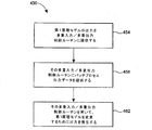
図9は、バッチプロセスの第1原理モデルをアップデートするための例示的な方法450のフローチャートである。この方法450は、例えば、図8のシステム404を用いて行われ、容易な説明のために、この方法450を図8を参照して説明する。しかし、当業者であれば、この方法450もまた、他のシステムを用いて行われることを理解するだろう。
Figure 9 is a flowchart of an
ブロック454において、第1原理モデルの出力が多重入力/多重出力制御ルーチンに提供され得る。例えば、図8では、第1原理モデル208の出力がモデルアップデートMPCブロック408に提供され得る。第1原理モデルの出力は、バッチプロセスの測定可能なリアルタイム変数の推定値を含むことができる。付加的にまたは選択的に、第1原理モデルの出力は、バッチプロセスの測定不可能なリアルタイム変数の推定値を含むことができる。ブロック454において提供されたデータは、例えば、データヒストリアンから検索されたデータを含むことができる。付加的にまたは選択的に、ブロック454に提供されるデータは、ワークステーション16、制御器12、フィールド装置等から検索されたデータを含むことができる。
In
ブロック458において、バッチプロセスと関連した出力データおよび第1原理モデルの出力に対応する出力データが多重入力/多重出力制御ルーチンに提供される。例えば、図8において、バッチプロセス212のデータ出力がモデルアップデートMPCブロック408に提供され得る。選択的に、その提供された出力データは実験室408からのデータを含むことができる。よって、その提供された出力データは第1原理モデルにより発生した測定不可能なリアルタイム変数の推定値に対応する出力データを付加的にまたは選択的に含むことができる。
In
ブロック462において、多重入力/多重出力制御システムは、第1原理モデルの変数を変更するように、ブロック454および458において受信されたデータに基づいて出力を発生することができる。例えば、第1原理モデルにより発生した推定する制御された変数と見なされ、実際プラントからの対応する測定された変数は、設定点と見なされ得る。その後、多重入力/多重出力制御システムは、その推定値が、その対応する測定された変数の追跡を試みることにより、第1原理モデルの変数を変更するように、データを発生することができる。調整されるモデル変数の一例は、Henry係数である。このHenry係数は、気相と液相との間の酸素の質量伝達を決める溶解酸素の平衡濃度を決めるための変数である。調整されるモデル変数の他の例では、活性化エネルギ、特定の反応、成長、質量伝達に対する係数、生成物および副産物の形成速度、酸素限界、基質抑制、細胞扶養、イオン解離、収率およびサイクル時間が挙げられる。
In
当業者であれば、多くの変更が可能であることを理解するだろう。例えば、第1原理モデルの出力および/または多重入力/多重出力制御システムに提供される対応する測定された変数は、短期的滞留をフィルタするためにフィルタリングされ得る。他の例として、多重入力/多重出力制御システムに提供される第1原理モデルの出力は、プロセスゲインと調整の範囲が相当な範囲内に維持されるようにスケーリングされ得る。また他の例として、バッチサイクルの適当な部分のみで、適合した変更が可能になるように、バッチサイクル間に、適合した変更が自動に開始および中止され得る。 One skilled in the art will appreciate that many changes are possible. For example, the corresponding measured variables are provided to the output and / or multiple input / multiple output control system of the first principle model may be filtered to filter short-term retention. As another example, the output of the first principle model provided in multiple input / multiple output control system can be scaled to the range of adjustment and the process gain is maintained within a reasonable range. As another example, adapted changes can be automatically started and stopped between batch cycles so that adapted changes are only possible in the appropriate part of the batch cycle.
図10は、本明細書で説明した技術を用いる例示的なバッチプロセスシステム500のブロック図である。このバッチプロセスシステム500は、ペニシリンを製造するように構成されている。このシステム500の多くの構成要素は、容易な説明のために図10に示されていない。このシステム500は、基質、塩基性試薬、酸性試薬および空気を収容する生物反応器504を含む。バッチの完了時、この生物反応器504は、バッチ排出管508を経由して排出される。ポンプ512は、塩基性試薬を生物反応器504に提供し、ポンプ514は、酸性試薬を生物反応器504に提供する。ポンプ512は、制御ルーチン516により制御され、ポンプ514は、制御ルーチン518により制御され得る。pHセンサ520は、生物反応器中のpHに関するデータを発生することができる。このpHデータは、スプリッタ522に提供され、すると、スプリッタ522は分割されたpHデータを制御ルーチン516および518に提供し、制御ルーチンは、生物反応器中のpHを制御するためにポンプ512および514を制御する。
FIG. 10 is a block diagram of an exemplary
ポンプ528は、生物反応器504に基質を提供し、ポンプ528は、制御ルーチン530により制御され得る。この基質は、グルコースを含むことができる。グルコース濃度センサ532が制御ルーチン530に生物反応器504内のグルコース濃度に関したデータを提供することができる。ポンプ536は、生物反応器504に空気を提供し、ポンプ536は、制御ルーチン538により制御され得る。生物反応器504へのベント542は、制御ルーチン544により制御され得る。
溶解酸素センサ520は、生物反応器504中の溶解酸素の濃度に関したデータを発生することができる。この溶解酸素データは、制御ルーチン550に提供される。今度は、制御ルーチン550は、スプリッタ554を経由して制御ルーチン538および制御ルーチン544に制御データを提供することができる。
The dissolved
MPC制御ブロック560は、上述した仮想プラントのような、バッチプロセスの第1原理モデルを有する仮想プラントからバイオマス成長速度および生成物形成速度の推定値を受信する。この推定されたバイオマス成長速度と推定された生成物の形成速度は、生物反応器504内の対応速度のリアルタイム推定値である。特に、この推定されたバイオマス成長速度は、生物反応器504内の菌細胞の成長速度の推定値であってもよく、この推定された生成物の形成速度は、生物反応器504内のペニシリン濃度の推定値であってもよい。
MPCブロック560は、第1の制御信号出力を発生し、制御ルーチン530に提供し、また第2の制御信号を発生し、制御ルーチン550に提供する。MPCブロック560により発生した出力は、制御ルーチン530および制御ルーチン550により使われる設定点であってもよい。例えば、制御ルーチン530に提供される第1の制御信号は、グルコース濃度設定点であってもよく、制御ルーチン550に提供される第2の制御信号は、溶解酸素濃度設定点であってもよい。よって、MPCブロック560は、推定されたバイオマス成長速度および推定された生成物形成速度に応答して、バッチの動作の間に、グルコース濃度設定点、溶解酸素濃度設定点を調整することができる。今度は、制御ルーチン530は、ポンプ536が、生物発生器504に多少の空気を付加するようにする制御データを発生することができ、生物発生器504内の多少の空気が排出するために、ベント542を調整するようにする制御データを発生することができる。
The
ペニシリンを製造するバッチプロセスでは、菌細胞にグルコースおよび溶解酸素が提供される。継続して、この菌細胞は、ペニシリンを分泌し、また二酸化炭素を発生する。一実施形態において、MPCブロック260を用いる制御は、バッチの開始後、生成速度がほぼ最大であると推定された時間まで用いられなかった。よって、MPCブロック260は、生成速度を一定して維持しようと試みるのに用いられた。 In a batch process for producing penicillin, fungal cells are provided with glucose and dissolved oxygen. Continuously, this fungal cell secretes penicillin and generates carbon dioxide. In one embodiment, control using MPC block 260 was not used until the time when the production rate was estimated to be approximately maximum after the start of the batch. Thus, MPC block 260 was used to try to keep the production rate constant.
細胞濃度が増加されることにより、さらに高い溶解酸素濃度が、バイオマス成長および生成物形成速度を徐々に増加させたものと観察された。しかし、高い空気流量は、ガス処理費用を増大させ、高い圧力は溶解した二酸化炭素を増加させ、よって、最小で有益な效果を有する場合は、溶解酸素がバッチの初期に低く維持された。低い基質濃度は、減少された基質抑制因子のため、バイオマス成長を減少させたが、生成物形成速度を増加させた。その結果、基質濃度は初期に細胞を成長するように高くしたが、その後、バッチが生成物形成を促進するように進行されるにつれて低くなった。MPCブロック560のチューニングは、バッチサイクルのフェドバッチ部分の間に、成長速度よりさらに重要であるので、移動に関するさらに高いペナルティーおよび生成速度誤差に関するさらに高いペナルティーを用いることを含んでもよい。 By increasing the cell concentration, higher dissolved oxygen concentrations were observed to gradually increase biomass growth and product formation rates. However, high air flow increased gas processing costs and high pressure increased dissolved carbon dioxide, so dissolved oxygen was kept low early in the batch if it had minimal beneficial effects. Low substrate concentration decreased biomass growth but increased product formation rate due to reduced substrate repressor. As a result, the substrate concentration was initially increased to grow the cells, but then decreased as the batch was advanced to promote product formation. Tuning the MPC block 560 may include using higher penalties for movement and higher penalties for production rate errors, as they are more important than the growth rate during the fed-batch portion of the batch cycle.
MPCブロック560は、純粋生成速度が低下しないようにすることができる。よって、MPCブロック560は、生成物濃度を一定の傾きで増加させることができ、バッチサイクル時間を短くすることができる。また、生成物濃度が一定の傾きで増加するので、バッチが完了する時間の推定が比較的正確ではなければならない。当業者であれば、システム500に多くの変更が可能であることを理解するだろう。その一例として、基質消耗速度を減少させ、純粋生成速度をさらによく維持するように制御器を自由に更新するために、バッチの末期付近では、バイオマス濃度プロファイルを減少させることが好ましいとすると、生成物濃度がその終点に近付くにつれ、成長速度に対する設定点が減少してもよい。
The
システム500により発生するバッチにおいて、残った時間量を予測するために、現在生成物濃度と終点濃度との間の差を係数化された純粋生成速度で割ることができる。以後、その残った時間量を現在のバッチ時間に加え、予測されたバッチサイクル時間を算出することができる。バッチ内の残った時間量に、係数化されたグルコース供給速度を掛けた後、現在のグルコースの総充填物に加えると、グルコース消耗量を予測することができる。生成物終点濃度をその予測されたグルコース消耗量で割ると、単位グルコースキログラム当たりの生成物キログラムで、予測された収率が算出される。今度は、予測された収率が、最小実際収率と最大実際収率との間の差のパーセントとして表現され得る。
To predict the amount of time remaining in the batch generated by the
勿論、図10のシステム500は、上述した技術を用いることができる生化学バッチプロセスシステムの一例に過ぎない。他の例では、他の抗生剤、合成タンパク質、成長ホルモン、抗体、調剤薬、添加剤、ビール、ワイン、ポリマー、滑剤、特殊化学品等を製造するためのシステムが挙げられる。
Of course, the
本明細書で説明した技術とシステムの他の実施形態は、多くの方法に活用され得る。例えば、図2に示したシステム、仮想プラント304のようなシステムは、正常バッチ動作および/または異常状況を制御および/または処理するための戦略を開発するのに用いられ得る。また、このようなシステムは、異常状況を検出するための戦略を開発するのに用いられ得る。また、ここで説明した技術とシステムの実施形態は、経済的目標を満たすバッチプロファイルを識別、予測、および/または達成するのに用いられ得る。バッチの終点は、予測され得、および/または、バッチプロセスは、生産能力および/または品質が増大するように制御され得る。バッチサイクル時間は、予測され得、および/またはバッチプロセスは、バッチサイクル時間が減少するように制御され得る。識別されたプロファイルは、保存され得、バッチでの変化量、動作条件、原材料(例えば、微量の栄養物、添加剤等)を検出し、および/または定量化するのに用いられ得る。プロファイルは、多変数統計的プロセス制御のようなツールにより分析されたア・プリオリであってもよい。 Other embodiments of the techniques and systems described herein can be utilized in many ways. For example, a system such as the system shown in FIG. 2, virtual plant 304, can be used to develop strategies for controlling and / or handling normal batch operations and / or abnormal situations. Such a system can also be used to develop strategies for detecting abnormal situations. Also, the techniques and system embodiments described herein may be used to identify, predict, and / or achieve batch profiles that meet economic goals. The end point of the batch can be predicted and / or the batch process can be controlled to increase production capacity and / or quality. The batch cycle time can be predicted and / or the batch process can be controlled to reduce the batch cycle time. The identified profiles can be stored and used to detect and / or quantify batch variations, operating conditions, raw materials (eg, trace nutrients, additives, etc.). The profile may be a priori analyzed by tools such as multivariable statistical process control.
本明細書では、MPCブロックのような、多くの多重入力/多重出力制御システムについて説明した。当業者であれば、既知のシステムを含む、多様な多重入力/多重出力制御システムが、本明細書で説明した技術の様々な実施形態に用いられ得ることを理解するだろう。例えば、次のいずれも譲渡された特許および特許出願は、選択的に用いられ得る技術およびシステムを開示している。次のいずれも譲渡された特許および特許出願は、本明細書に全体が参照され組み込まれる。米国特許第6,445,963号は、多重入力/多重出力制御を行う拡張制御ブロックのみならず、そのような制御ブロックを生成して構成する技術を開示している。米国特許第6,721,609号は、操作された制御変数が制限を超過し、または違反しないことを保障するために、制御ロジックの最適化を行う多重入力/多重出力制御ブロックを開示している。米国特許第6,901,308号は、プロセスの相違した動作領域に対して、多重入力/多重出力制御ブロックの実行期間を変更する補償ブロックまたはアルゴリズムを含む多重入力/多重出力制御ブロックを開示している。米国特許出願第10/241,350号は、操作された変数に対して、最適の動作目標値を計算する最適化ルーチンを含む多重入力/多重出力制御ブロックを開示している。米国特許出願第10/454,937号は、制御されたプロセスをモデリングする線形プロセスモデルおよび線形プロセスモデルの予測値に対する補正値を発生する非線形プロセスモデルを含む多重入力/多重出力制御ブロックを開示している。これは、非線形特性を持つプロセスの制御を向上させることができる。 A number of multiple input / multiple output control systems have been described herein, such as MPC blocks. Those skilled in the art will appreciate that a variety of multiple input / multiple output control systems, including known systems, can be used in various embodiments of the techniques described herein. For example, any of the following assigned patents and patent applications disclose techniques and systems that can be used selectively. All of the following assigned patents and patent applications are hereby incorporated by reference in their entirety: US Pat. No. 6,445,963 discloses not only an extended control block that performs multiple input / multiple output control, but also a technique for generating and configuring such a control block. US Pat. No. 6,721,609 discloses a multiple input / multiple output control block that performs control logic optimization to ensure that manipulated control variables do not exceed or violate limits. Yes. US Pat. No. 6,901,308 discloses a multiple input / multiple output control block including a compensation block or algorithm that changes the execution period of the multiple input / multiple output control block for different operating regions of the process. ing. US patent application Ser. No. 10 / 241,350 discloses a multiple input / multiple output control block that includes an optimization routine that calculates an optimal operating target value for the manipulated variables. US patent application Ser. No. 10 / 454,937 discloses a multiple input / multiple output control block including a linear process model for modeling a controlled process and a non-linear process model for generating correction values for predicted values of the linear process model. ing. This can improve the control of processes with non-linear characteristics.
本明細書で説明した、多重入力/多重出力制御システム、第1原理モデル、制御ルーチン、方法ブロック等は、いかなるハードウェア、ファームウエア、およびソフトウェアの組合せを用いても実行され得る。従って、本明細書で説明したシステムと技術は、標準的な多目的プロセッサで行われ、または所望に応じて、特に設計されたハードウェアまたはファームウエアを用いて行われ得る。ソフトウェアで行われる場合、ソフトウェアは、マグネチックディスク、レーザーディスク(登録商標)、または他の格納媒体のような、いかなるコンピュータで読取可能なメモリ、RAMまたはROMまたはコンピュータまたはプロセッサのフラッシュメモリ等に保存されることが可能である。これと同様に、ソフトウェアは、使用者またはプロセス制御システムに、例えばコンピュータで読取可能なディスクまたは他の伝達可能なコンピュータ保存メカニズムを含む、いかなる公知または好適な伝達方法を通じて、または通信媒体を通じて伝達され得る。一般に、通信媒体は、コンピュータで読取可能な命令語、データ構造、プログラムモジュール、または他のデータを、搬送波または他の伝達メカニズムのような変調されたデータ信号で含む。「変調されたデータ信号」との用語は、その一つ以上の特性が信号内の情報をエンコードすることができる方式で設定され、または変更された信号を意味する。例として、通信媒体としては、有線網または直通有線接続のような有線媒体、そして、音波、RF、超音波および他の有線媒体のような無線媒体が挙げられ、これに限らない。よって、ソフトウェアは、(同一のものと視認され、または伝達保存媒体を通じてそのようなソフトウェアを提供して相互交換することが可能な)電話線、インターネット等のような通信チャンネルを通じて、使用者またはプロセス制御システムに伝達され得る。 Described herein, multiple-input / multiple-output control system, the first principle model, a control routine, the method blocks or the like, any hardware may be executed by using a firmware, and software combinations. Thus, the systems and techniques described herein may be performed with a standard multipurpose processor, or may be performed with specially designed hardware or firmware, as desired. If done in software, the software is stored in any computer readable memory, RAM or ROM, or flash memory of a computer or processor, such as a magnetic disk, laser disk, or other storage medium. Can be done. Similarly, the software is communicated to the user or process control system through any known or suitable transmission method or communication medium including, for example, a computer readable disk or other transferable computer storage mechanism. obtain. Generally, communication media include computer readable instructions, data structures, program modules, or other data in a modulated data signal such as a carrier wave or other transport mechanism. The term “modulated data signal” means a signal that has one or more of its characteristics set or changed in such a manner as to encode information in the signal. By way of example, communication media includes, but is not limited to, wired media such as a wired network or direct wired connection, and wireless media such as sonic, RF, ultrasonic and other wired media. Thus, the software can be used by a user or process over a communication channel such as a telephone line, the Internet, etc. (which can be viewed as the same or provided and interchangeable through a transmission storage medium). Can be communicated to the control system.
よって、本発明を特定例を参考して説明したが、これは、単に例示に過ぎず、本発明を限定するものではなく、本発明の精神と範疇から逸脱しない範囲内で、開示された実施形態に対して、変更、追加または削除が可能であることは当業者にとって明白であるだろう。 Thus, although the present invention has been described with reference to specific examples, this is merely illustrative and is not intended to limit the invention, and to the disclosed implementations without departing from the spirit and scope of the invention. It will be apparent to those skilled in the art that changes, additions or deletions can be made to the form.
Claims (18)
前記推定値を前記バッチプロセスを制御するためのプロセス制御ルーチンに提供するステップと、
前記バッチプロセスを制御するために、前記プロセス制御ルーチンを用いて、前記推定値に基づいて信号を発生するステップと、
前記第1原理モデルの出力と前記バッチプロセスからの測定値との比較に基づいて前記第1原理モデルの少なくとも1つの変数をアップデートするステップと、
を含む、バッチプロセスを制御する方法。 A step of using the first principle model, generates an estimate of unmeasurable real-time parameters of the batch process,
Providing the estimate to a process control routine for controlling the batch process;
Generating a signal based on the estimate using the process control routine to control the batch process ;
Updating at least one variable of the first principle model based on a comparison of an output of the first principle model and a measured value from the batch process;
A method for controlling a batch process, including:
前記一つ以上の追加の推定値を前記プロセス制御ルーチンに提供するステップと、を含み、
前記バッチプロセスを制御するために信号を発生するステップは、前記プロセス制御ルーチンを用いて、前記推定値および前記一つ以上の追加の推定値に基づいて、信号を発生するステップを含む、
請求項1に記載の方法。 A step of using the first principle model, generates one or more additional estimate of the additional unmeasurable real-time parameters of the batch process,
Comprises the steps of providing said one or more additional estimated value to the process control routine,
Generating a signal to control the batch process includes generating a signal based on the estimate and the one or more additional estimates using the process control routine;
The method of claim 1.
前記バッチプロセスを制御するために信号を発生するステップは、前記プロセス制御ルーチンを用いて、前記推定値および前記一つ以上の測定されたバッチプロセス変数に基づいて、信号を発生するステップを含む、
請求項1に記載の方法。 Providing one or more measured batch process variables to the process control routine;
Generating a signal to control the batch process includes generating a signal based on the estimate and the one or more measured batch process variables using the process control routine;
The method of claim 1.
請求項1に記載の方法。 The process control routine includes a multiple input / multiple output control routine,
The method of claim 1.
請求項4に記載の方法。 The process control routine includes a model predictive control routine,
The method of claim 4.
請求項1に記載の方法。 Generating an estimate of the unmeasurable real-time variable includes generating an estimate of a component change rate of an element of a batch process;
The method of claim 1.
前記バッチプロセスと関連した維持時間を制御するために信号を発生するステップ、
前記バッチプロセスと関連した変数の変化速度を制御するために信号を発生するステップ、または
前記バッチプロセスと関連したバッチサイクル時間を制御するために信号を発生するステップのうち少なくとも一つを含む、
請求項1に記載の方法。 Generating a signal to control the batch process comprises:
Generating a signal to control a maintenance time associated with the batch process;
At least one of generating a signal to control a rate of change of a variable associated with the batch process, or generating a signal to control a batch cycle time associated with the batch process;
The method of claim 1.
前記設定点を追加のプロセス制御ルーチンに提供するステップをさらに含む、
請求項1に記載の方法。 Generating a signal to control the batch process includes generating a set point for use in other process control routines;
Providing the set point to an additional process control routine;
The method of claim 1.
請求項1に記載の方法。The method of claim 1.
バッチプロセスの少なくとも一つの測定不可能なリアルタイム変数に対応する、少なくとも一つの推定値を発生するように構成された第1原理モデルと、
前記少なくとも一つの推定値を前記第1原理モデルから受信し、前記少なくとも一つの推定値に基づいて前記バッチプロセスを制御するための制御信号を発生するように構成された、前記コンピュータ可読媒体に格納された第1の多重入力/多重出力制御ルーチンと、
前記第1原理モデルの出力と前記バッチプロセスからの測定値との比較に基づいて前記第1原理モデルの少なくとも1つの変数をアップデートするよう構成された、前記コンピュータ可読媒体に格納された第2の多重入力/多重出力制御ルーチンと、
を含む、バッチプロセスを制御するためのシステム。 A computer readable medium;
Corresponding to at least one of the unmeasurable real-time parameters of the batch process, a first principle model configured to generate at least one estimate,
Stored in the computer readable medium configured to receive the at least one estimate from the first principle model and to generate a control signal for controlling the batch process based on the at least one estimate. A first multiple input / multiple output control routine ,
A second stored in the computer readable medium configured to update at least one variable of the first principle model based on a comparison of the output of the first principle model and a measurement from the batch process. A multiple input / multiple output control routine;
A system for controlling batch processes , including:
請求項10に記載のシステム。 The first multiple input / multiple output control routine includes a model predictive control routine;
The system according to claim 10 .
前記第1の多重入力/多重出力制御ルーチンは、前記少なくとも一つの推定値および前記少なくとも一つの測定された変数に基づいて、前記バッチプロセスを制御するための制御信号を発生するように構成される、
請求項10に記載のシステム。 The first multiple input / multiple output control routine is communicatively coupled to receive at least one measured variable of the batch process;
It said first multiple-input / multiple-output control routine, based on the at least one estimated value and the at least one measured variable, Ru is configured to generate a control signal for controlling the batch process ,
The system according to claim 10 .
請求項10に記載のシステム。 It said control signal generated by said first multiple-input / multiple-output control routine, Ru is communicatively connected to an input of the first principle model,
The system according to claim 10 .
前記第3の多重入力/多重出力制御ルーチンにより発生した制御信号は、前記第1原理モデルの入力に通信可能に接続される、
請求項10に記載のシステム。 Receiving the at least one estimate from the first principle model and generating a control signal for controlling the batch process based on the at least one estimate and stored on the computer readable medium A third multiple input / multiple output control routine;
Control signal generated by said third multiple-input / multiple-output control routine, Ru is communicatively connected to an input of the first principle model,
The system according to claim 10 .
請求項10に記載のシステム。The system according to claim 10.
前記バッチプロセスの第1原理モデルにより発生する推定値を、入力として前記多重入力/多重出力制御ルーチンに提供するステップと、
前記多重入力/多重出力制御ルーチンにより発生した出力を用いて、前記第1原理モデルの変数をアップデートするステップと、
を含む、バッチプロセスのモデルをアップデートする方法。 Providing measurements associated with the batch process as inputs to a multiple input / multiple output control routine;
And providing an estimate generated by the first principle model of the batch process, the multiple-input / multiple-output control routine as inputs,
A step of updating by the variable of the first principle model using the output generated by the multiple-input / multiple-output control routine,
To update the batch process model, including
請求項16に記載の方法。 The multiple input / multiple output control routine includes a model predictive control routine;
The method of claim 16 .
請求項16に記載の方法。The method of claim 16.
Applications Claiming Priority (2)
| Application Number | Priority Date | Filing Date | Title |
|---|---|---|---|
| US11/241157 | 2005-09-30 | ||
| US11/241,157 US7877154B2 (en) | 2005-09-30 | 2005-09-30 | Method and system for controlling a batch process |
Related Child Applications (1)
| Application Number | Title | Priority Date | Filing Date |
|---|---|---|---|
| JP2011281104A Division JP5479443B2 (en) | 2005-09-30 | 2011-12-22 | System and method for controlling a batch process |
Publications (3)
| Publication Number | Publication Date |
|---|---|
| JP2007188473A JP2007188473A (en) | 2007-07-26 |
| JP2007188473A5 true JP2007188473A5 (en) | 2012-02-16 |
| JP5331301B2 JP5331301B2 (en) | 2013-10-30 |
Family
ID=37421252
Family Applications (2)
| Application Number | Title | Priority Date | Filing Date |
|---|---|---|---|
| JP2006270333A Active JP5331301B2 (en) | 2005-09-30 | 2006-10-02 | System and method for controlling a batch process |
| JP2011281104A Active JP5479443B2 (en) | 2005-09-30 | 2011-12-22 | System and method for controlling a batch process |
Family Applications After (1)
| Application Number | Title | Priority Date | Filing Date |
|---|---|---|---|
| JP2011281104A Active JP5479443B2 (en) | 2005-09-30 | 2011-12-22 | System and method for controlling a batch process |
Country Status (6)
| Country | Link |
|---|---|
| US (1) | US7877154B2 (en) |
| JP (2) | JP5331301B2 (en) |
| CN (2) | CN102841538B (en) |
| DE (1) | DE102006045428B4 (en) |
| GB (3) | GB2465513B (en) |
| HK (3) | HK1098835A1 (en) |
Families Citing this family (59)
| Publication number | Priority date | Publication date | Assignee | Title |
|---|---|---|---|---|
| US7689296B2 (en) * | 2006-04-28 | 2010-03-30 | Honeywell Asca Inc. | Apparatus and method for controlling a paper machine or other machine using measurement predictions based on asynchronous sensor information |
| US7747416B2 (en) * | 2006-06-06 | 2010-06-29 | Siemens Industry, Inc. | System and method for batch process control with diverse distributed control system protocols |
| US8527252B2 (en) * | 2006-07-28 | 2013-09-03 | Emerson Process Management Power & Water Solutions, Inc. | Real-time synchronized control and simulation within a process plant |
| US7949417B2 (en) | 2006-09-22 | 2011-05-24 | Exxonmobil Research And Engineering Company | Model predictive controller solution analysis process |
| US20080103747A1 (en) * | 2006-10-31 | 2008-05-01 | Macharia Maina A | Model predictive control of a stillage sub-process in a biofuel production process |
| US8521310B2 (en) * | 2006-10-31 | 2013-08-27 | Rockwell Automation Technologies, Inc. | Integrated model predictive control of distillation and dehydration sub-processes in a biofuel production process |
| US7933849B2 (en) * | 2006-10-31 | 2011-04-26 | Rockwell Automation Technologies, Inc. | Integrated model predictive control of batch and continuous processes in a biofuel production process |
| US7831318B2 (en) * | 2006-10-31 | 2010-11-09 | Rockwell Automation Technologies, Inc. | Model predictive control of fermentation temperature in biofuel production |
| US8571690B2 (en) * | 2006-10-31 | 2013-10-29 | Rockwell Automation Technologies, Inc. | Nonlinear model predictive control of a biofuel fermentation process |
| US8634940B2 (en) * | 2006-10-31 | 2014-01-21 | Rockwell Automation Technologies, Inc. | Model predictive control of a fermentation feed in biofuel production |
| US7844350B2 (en) * | 2006-11-22 | 2010-11-30 | Honeywell International Inc. | Testing of control strategies in a control system controlling a process control plant |
| US7840363B2 (en) * | 2008-03-20 | 2010-11-23 | Rockwell Automation Technologies, Inc. | Determining total mill flow in a biofuel production process |
| US9298174B2 (en) * | 2008-03-20 | 2016-03-29 | Rockwell Automation Technologies, Inc. | Determining total inventory of batch and continuous inventories in a biofuel production process |
| US8755939B2 (en) * | 2008-06-30 | 2014-06-17 | Rockwell Automation Technologies, Inc. | Throughput/yield optimized model predictive control |
| US20100063786A1 (en) * | 2008-09-11 | 2010-03-11 | Harke Michael C | Co-Simulation Process |
| US8103385B2 (en) * | 2008-09-30 | 2012-01-24 | Rockwell Automation Technologies, Inc. | Optimizing product drying through parallel lines of centrifuges and dryer process units |
| US9014858B2 (en) * | 2008-09-30 | 2015-04-21 | Rockwell Automation Technologies, Inc. | Energy optimizer for dehydrating biofuels through distillation towers and molecular sieves |
| US9037298B2 (en) * | 2008-09-30 | 2015-05-19 | Rockwell Automation Technologies, Inc. | Cook flash temperature optimization |
| US9098093B2 (en) * | 2008-09-30 | 2015-08-04 | Rockwell Automation Technologies, Inc. | Model predictive control of biofuel denaturant blending |
| US20100124263A1 (en) * | 2008-11-19 | 2010-05-20 | Harris Corporation | Systems for determining a reference signal at any location along a transmission media |
| US8170088B2 (en) * | 2008-11-19 | 2012-05-01 | Harris Corporation | Methods for determining a reference signal at any location along a transmission media |
| US20100123618A1 (en) * | 2008-11-19 | 2010-05-20 | Harris Corporation | Closed loop phase control between distant points |
| US20100125347A1 (en) * | 2008-11-19 | 2010-05-20 | Harris Corporation | Model-based system calibration for control systems |
| US7969358B2 (en) * | 2008-11-19 | 2011-06-28 | Harris Corporation | Compensation of beamforming errors in a communications system having widely spaced antenna elements |
| US7855681B2 (en) * | 2008-11-19 | 2010-12-21 | Harris Corporation | Systems and methods for determining element phase center locations for an array of antenna elements |
| US7970365B2 (en) * | 2008-11-19 | 2011-06-28 | Harris Corporation | Systems and methods for compensating for transmission phasing errors in a communications system using a receive signal |
| WO2011067559A1 (en) | 2009-12-01 | 2011-06-09 | Oxford Nanopore Technologies Limited | Biochemical analysis instrument |
| US8756039B2 (en) * | 2010-03-02 | 2014-06-17 | Fisher-Rosemount Systems, Inc. | Rapid process model identification and generation |
| US9182752B2 (en) | 2010-05-21 | 2015-11-10 | Fisher-Rosemount Systems, Inc. | Method and system for multi-zone modeling to determine material properties in storage tanks |
| CN102906650B (en) * | 2010-05-21 | 2016-07-13 | 费希尔-罗斯蒙特系统公司 | Multistage process modeling approach |
| US9447963B2 (en) | 2010-08-16 | 2016-09-20 | Emerson Process Management Power & Water Solutions, Inc. | Dynamic tuning of dynamic matrix control of steam temperature |
| US9335042B2 (en) | 2010-08-16 | 2016-05-10 | Emerson Process Management Power & Water Solutions, Inc. | Steam temperature control using dynamic matrix control |
| US9217565B2 (en) | 2010-08-16 | 2015-12-22 | Emerson Process Management Power & Water Solutions, Inc. | Dynamic matrix control of steam temperature with prevention of saturated steam entry into superheater |
| WO2012107778A2 (en) | 2011-02-11 | 2012-08-16 | Oxford Nanopore Technologies Limited | Mutant pores |
| US8788239B2 (en) * | 2011-02-11 | 2014-07-22 | Fisher-Rosemount Systems, Inc. | Methods, apparatus and articles of manufacture to test batch configurations |
| US9163828B2 (en) | 2011-10-31 | 2015-10-20 | Emerson Process Management Power & Water Solutions, Inc. | Model-based load demand control |
| WO2013087973A1 (en) * | 2011-12-16 | 2013-06-20 | Metso Automation Oy | Method of tuning a process controller |
| WO2013153359A1 (en) | 2012-04-10 | 2013-10-17 | Oxford Nanopore Technologies Limited | Mutant lysenin pores |
| JP5969919B2 (en) * | 2012-12-28 | 2016-08-17 | アズビル株式会社 | Optimization device and method, and control device and method |
| GB201313477D0 (en) | 2013-07-29 | 2013-09-11 | Univ Leuven Kath | Nanopore biosensors for detection of proteins and nucleic acids |
| CN103268069B (en) * | 2013-05-22 | 2015-10-28 | 常州大学 | Based on the adaptive prediction control method of Hammerstein model |
| US10018997B2 (en) | 2013-06-28 | 2018-07-10 | Fisher-Rosemount Systems, Inc. | Non-intrusive data analytics in a process control system |
| DE102013108478A1 (en) * | 2013-08-06 | 2015-02-12 | Endress+Hauser Process Solutions Ag | Method for expanding an embedded software component of a field device |
| US10443097B2 (en) | 2014-05-02 | 2019-10-15 | Oxford Nanopore Technologies Ltd. | Method of improving the movement of a target polynucleotide with respect to a transmembrane pore |
| CN106575104B (en) * | 2014-08-13 | 2021-10-15 | 费希尔-罗斯蒙特系统公司 | Model predictive control using wireless process signals |
| CN117164682A (en) | 2014-09-01 | 2023-12-05 | 弗拉芒区生物技术研究所 | Mutant CSGG wells |
| WO2016055778A1 (en) | 2014-10-07 | 2016-04-14 | Oxford Nanopore Technologies Limited | Mutant pores |
| US10394973B2 (en) * | 2015-12-18 | 2019-08-27 | Fisher-Rosemount Systems, Inc. | Methods and apparatus for using analytical/statistical modeling for continued process verification (CPV) |
| US10338549B2 (en) * | 2016-10-17 | 2019-07-02 | Fisher-Rosemount Systems, Inc. | Methods and systems for subscribing remote devices to process control data |
| US10656635B2 (en) * | 2016-12-02 | 2020-05-19 | Honeywell International Inc. | Apparatus and method for performing process simulations for embedded multivariable predictive controllers in industrial process control and automation systems |
| CN109600245B (en) * | 2017-09-30 | 2021-11-19 | 北京国双科技有限公司 | Automatic configuration method and device for server |
| CN107991886B (en) * | 2017-12-28 | 2020-08-28 | 杭州电子科技大学 | Prediction optimization control method for waste plastic gasification oil refining hearth pressure |
| JP7036128B2 (en) * | 2018-01-16 | 2022-03-15 | 日本電気株式会社 | Controls, control methods and programs |
| EP3671373A1 (en) * | 2018-12-19 | 2020-06-24 | Bystronic Laser AG | Forecasting method for predicting the machining result for a laser machining method |
| CN109981467B (en) * | 2019-03-29 | 2022-02-11 | 中国人民银行清算总中心 | Static route updating method and route centralized management distribution method |
| US11899417B2 (en) * | 2019-05-02 | 2024-02-13 | Fisher-Rosemount Systems, Inc. | Methods and apparatus to implement predictive analytics for continuous control system processes |
| US11604459B2 (en) | 2019-07-12 | 2023-03-14 | Emerson Process Management Power & Water Solutions, Inc. | Real-time control using directed predictive simulation within a control system of a process plant |
| US20220283561A1 (en) * | 2021-01-29 | 2022-09-08 | Tata Consultancy Services Limited | Method and system to control a continuous bioprocessing |
| US20220308978A1 (en) * | 2021-03-24 | 2022-09-29 | International Business Machines Corporation | Task simulation using revised goals |
Family Cites Families (21)
| Publication number | Priority date | Publication date | Assignee | Title |
|---|---|---|---|---|
| US7149590B2 (en) | 1996-05-06 | 2006-12-12 | Pavilion Technologies, Inc. | Kiln control and upset recovery using a model predictive control in series with forward chaining |
| KR100205691B1 (en) * | 1997-04-29 | 1999-07-01 | 정순착 | Hybrid predictor and hybrid predicting method for process control |
| US6445963B1 (en) * | 1999-10-04 | 2002-09-03 | Fisher Rosemount Systems, Inc. | Integrated advanced control blocks in process control systems |
| JP2001106703A (en) * | 1999-10-06 | 2001-04-17 | Mitsubishi Rayon Co Ltd | System for predicting quality and controlling reaction |
| US6654649B2 (en) | 1999-12-22 | 2003-11-25 | Aspen Technology, Inc. | Computer method and apparatus for optimized controller in a non-linear process |
| JP2001249705A (en) * | 2000-03-03 | 2001-09-14 | Toshiba Corp | Process simulator application non-linear controller and method for the same |
| GB0005866D0 (en) | 2000-03-10 | 2000-05-03 | Borealis Polymers Oy | Process control system |
| US6826521B1 (en) * | 2000-04-06 | 2004-11-30 | Abb Automation Inc. | System and methodology and adaptive, linear model predictive control based on rigorous, nonlinear process model |
| US6760716B1 (en) * | 2000-06-08 | 2004-07-06 | Fisher-Rosemount Systems, Inc. | Adaptive predictive model in a process control system |
| US6721609B1 (en) * | 2000-06-14 | 2004-04-13 | Fisher-Rosemount Systems, Inc. | Integrated optimal model predictive control in a process control system |
| WO2002005042A2 (en) * | 2000-07-12 | 2002-01-17 | Aspen Technology, Inc. | Automated closed loop step testing of process units |
| JP2002041108A (en) * | 2000-07-25 | 2002-02-08 | Yokogawa Electric Corp | Process control method and process controller using the same |
| US6819963B2 (en) * | 2000-12-06 | 2004-11-16 | Advanced Micro Devices, Inc. | Run-to-run control method for proportional-integral-derivative (PID) controller tuning for rapid thermal processing (RTP) |
| JP3864781B2 (en) * | 2001-12-28 | 2007-01-10 | オムロン株式会社 | air conditioner |
| US6901308B1 (en) * | 2002-07-09 | 2005-05-31 | The Regents Of The University Of California | System level analysis and control of manufacturing process variation |
| US7376472B2 (en) * | 2002-09-11 | 2008-05-20 | Fisher-Rosemount Systems, Inc. | Integrated model predictive control and optimization within a process control system |
| US7242989B2 (en) * | 2003-05-30 | 2007-07-10 | Fisher-Rosemount Systems, Inc. | Apparatus and method for batch property estimation |
| US7272454B2 (en) * | 2003-06-05 | 2007-09-18 | Fisher-Rosemount Systems, Inc. | Multiple-input/multiple-output control blocks with non-linear predictive capabilities |
| US20050193739A1 (en) * | 2004-03-02 | 2005-09-08 | General Electric Company | Model-based control systems and methods for gas turbine engines |
| US7203554B2 (en) * | 2004-03-16 | 2007-04-10 | United Technologies Corporation | Model predictive controller with life extending control |
| US7117046B2 (en) * | 2004-08-27 | 2006-10-03 | Alstom Technology Ltd. | Cascaded control of an average value of a process parameter to a desired value |
-
2005
- 2005-09-30 US US11/241,157 patent/US7877154B2/en active Active
-
2006
- 2006-09-20 GB GB1003382A patent/GB2465513B/en active Active
- 2006-09-20 GB GB0618442A patent/GB2430763B/en active Active
- 2006-09-20 GB GB1008266A patent/GB2467683B/en active Active
- 2006-09-26 DE DE102006045428.6A patent/DE102006045428B4/en active Active
- 2006-09-30 CN CN201210297341.0A patent/CN102841538B/en active Active
- 2006-09-30 CN CN2006101317512A patent/CN1940781B/en active Active
- 2006-10-02 JP JP2006270333A patent/JP5331301B2/en active Active
-
2007
- 2007-04-13 HK HK07103885.5A patent/HK1098835A1/en not_active IP Right Cessation
-
2010
- 2010-11-26 HK HK11102216.1A patent/HK1148083A1/en not_active IP Right Cessation
- 2010-11-26 HK HK10110991.6A patent/HK1144715A1/en not_active IP Right Cessation
-
2011
- 2011-12-22 JP JP2011281104A patent/JP5479443B2/en active Active
Similar Documents
| Publication | Publication Date | Title |
|---|---|---|
| JP5331301B2 (en) | System and method for controlling a batch process | |
| JP2007188473A5 (en) | ||
| CN106575104B (en) | Model predictive control using wireless process signals | |
| US7272454B2 (en) | Multiple-input/multiple-output control blocks with non-linear predictive capabilities | |
| JP4786072B2 (en) | Multi-input / multi-output logic device and method for controlling a process using the multi-input / multi-output logic device | |
| US6901300B2 (en) | Adaptation of advanced process control blocks in response to variable process delay | |
| CN102906650B (en) | Multistage process modeling approach | |
| EP2118711B1 (en) | Apparatus and method for automated closed-loop identification of an industrial process in a process control system. | |
| CN101807048B (en) | On-line adaptive model predictive control in process control system | |
| JP5476418B2 (en) | Apparatus and method for batch property estimation | |
| US8756039B2 (en) | Rapid process model identification and generation | |
| CZ20023362A3 (en) | Method and control device for controlling a process | |
| CN1490690A (en) | Integrated model predicting control and optimization in process control system | |
| JP2015011722A (en) | Non-intrusive data analytics in process control system | |
| CN1490691A (en) | Arrangement of integrated module predicting control and optimizing block and observation display | |
| US20130184837A1 (en) | Compensating for setpoint changes in a non-periodically updated controller | |
| EP4202582A1 (en) | Method of operation of a process plant, soft sensor and digital process twin system and use thereof | |
| Bonvin et al. | Control and optimization of batch chemical processes |