JP2007184228A - Flat fuel cell assembly provided with connector - Google Patents
Flat fuel cell assembly provided with connector Download PDFInfo
- Publication number
- JP2007184228A JP2007184228A JP2006194701A JP2006194701A JP2007184228A JP 2007184228 A JP2007184228 A JP 2007184228A JP 2006194701 A JP2006194701 A JP 2006194701A JP 2006194701 A JP2006194701 A JP 2006194701A JP 2007184228 A JP2007184228 A JP 2007184228A
- Authority
- JP
- Japan
- Prior art keywords
- fuel cell
- flat plate
- membrane
- cell assembly
- electrode
- Prior art date
- Legal status (The legal status is an assumption and is not a legal conclusion. Google has not performed a legal analysis and makes no representation as to the accuracy of the status listed.)
- Pending
Links
Images


Classifications
-
- H—ELECTRICITY
- H01—ELECTRIC ELEMENTS
- H01M—PROCESSES OR MEANS, e.g. BATTERIES, FOR THE DIRECT CONVERSION OF CHEMICAL ENERGY INTO ELECTRICAL ENERGY
- H01M8/00—Fuel cells; Manufacture thereof
- H01M8/24—Grouping of fuel cells, e.g. stacking of fuel cells
- H01M8/2465—Details of groupings of fuel cells
- H01M8/247—Arrangements for tightening a stack, for accommodation of a stack in a tank or for assembling different tanks
- H01M8/248—Means for compression of the fuel cell stacks
-
- F—MECHANICAL ENGINEERING; LIGHTING; HEATING; WEAPONS; BLASTING
- F21—LIGHTING
- F21K—NON-ELECTRIC LIGHT SOURCES USING LUMINESCENCE; LIGHT SOURCES USING ELECTROCHEMILUMINESCENCE; LIGHT SOURCES USING CHARGES OF COMBUSTIBLE MATERIAL; LIGHT SOURCES USING SEMICONDUCTOR DEVICES AS LIGHT-GENERATING ELEMENTS; LIGHT SOURCES NOT OTHERWISE PROVIDED FOR
- F21K9/00—Light sources using semiconductor devices as light-generating elements, e.g. using light-emitting diodes [LED] or lasers
- F21K9/60—Optical arrangements integrated in the light source, e.g. for improving the colour rendering index or the light extraction
- F21K9/68—Details of reflectors forming part of the light source
-
- F—MECHANICAL ENGINEERING; LIGHTING; HEATING; WEAPONS; BLASTING
- F21—LIGHTING
- F21S—NON-PORTABLE LIGHTING DEVICES; SYSTEMS THEREOF; VEHICLE LIGHTING DEVICES SPECIALLY ADAPTED FOR VEHICLE EXTERIORS
- F21S8/00—Lighting devices intended for fixed installation
- F21S8/04—Lighting devices intended for fixed installation intended only for mounting on a ceiling or the like overhead structures
-
- F—MECHANICAL ENGINEERING; LIGHTING; HEATING; WEAPONS; BLASTING
- F21—LIGHTING
- F21V—FUNCTIONAL FEATURES OR DETAILS OF LIGHTING DEVICES OR SYSTEMS THEREOF; STRUCTURAL COMBINATIONS OF LIGHTING DEVICES WITH OTHER ARTICLES, NOT OTHERWISE PROVIDED FOR
- F21V17/00—Fastening of component parts of lighting devices, e.g. shades, globes, refractors, reflectors, filters, screens, grids or protective cages
- F21V17/10—Fastening of component parts of lighting devices, e.g. shades, globes, refractors, reflectors, filters, screens, grids or protective cages characterised by specific fastening means or way of fastening
- F21V17/105—Fastening of component parts of lighting devices, e.g. shades, globes, refractors, reflectors, filters, screens, grids or protective cages characterised by specific fastening means or way of fastening using magnets
-
- F—MECHANICAL ENGINEERING; LIGHTING; HEATING; WEAPONS; BLASTING
- F21—LIGHTING
- F21V—FUNCTIONAL FEATURES OR DETAILS OF LIGHTING DEVICES OR SYSTEMS THEREOF; STRUCTURAL COMBINATIONS OF LIGHTING DEVICES WITH OTHER ARTICLES, NOT OTHERWISE PROVIDED FOR
- F21V19/00—Fastening of light sources or lamp holders
- F21V19/001—Fastening of light sources or lamp holders the light sources being semiconductors devices, e.g. LEDs
- F21V19/003—Fastening of light source holders, e.g. of circuit boards or substrates holding light sources
-
- F—MECHANICAL ENGINEERING; LIGHTING; HEATING; WEAPONS; BLASTING
- F21—LIGHTING
- F21V—FUNCTIONAL FEATURES OR DETAILS OF LIGHTING DEVICES OR SYSTEMS THEREOF; STRUCTURAL COMBINATIONS OF LIGHTING DEVICES WITH OTHER ARTICLES, NOT OTHERWISE PROVIDED FOR
- F21V21/00—Supporting, suspending, or attaching arrangements for lighting devices; Hand grips
- F21V21/02—Wall, ceiling, or floor bases; Fixing pendants or arms to the bases
- F21V21/04—Recessed bases
- F21V21/041—Mounting arrangements specially adapted for false ceiling panels or partition walls made of plates
- F21V21/042—Mounting arrangements specially adapted for false ceiling panels or partition walls made of plates using clamping means, e.g. for clamping with panel or wall
- F21V21/043—Mounting arrangements specially adapted for false ceiling panels or partition walls made of plates using clamping means, e.g. for clamping with panel or wall actuated by screwing
-
- F—MECHANICAL ENGINEERING; LIGHTING; HEATING; WEAPONS; BLASTING
- F21—LIGHTING
- F21V—FUNCTIONAL FEATURES OR DETAILS OF LIGHTING DEVICES OR SYSTEMS THEREOF; STRUCTURAL COMBINATIONS OF LIGHTING DEVICES WITH OTHER ARTICLES, NOT OTHERWISE PROVIDED FOR
- F21V7/00—Reflectors for light sources
- F21V7/04—Optical design
- F21V7/041—Optical design with conical or pyramidal surface
-
- H—ELECTRICITY
- H01—ELECTRIC ELEMENTS
- H01M—PROCESSES OR MEANS, e.g. BATTERIES, FOR THE DIRECT CONVERSION OF CHEMICAL ENERGY INTO ELECTRICAL ENERGY
- H01M8/00—Fuel cells; Manufacture thereof
- H01M8/002—Shape, form of a fuel cell
- H01M8/006—Flat
-
- H—ELECTRICITY
- H01—ELECTRIC ELEMENTS
- H01M—PROCESSES OR MEANS, e.g. BATTERIES, FOR THE DIRECT CONVERSION OF CHEMICAL ENERGY INTO ELECTRICAL ENERGY
- H01M8/00—Fuel cells; Manufacture thereof
- H01M8/02—Details
-
- H—ELECTRICITY
- H01—ELECTRIC ELEMENTS
- H01M—PROCESSES OR MEANS, e.g. BATTERIES, FOR THE DIRECT CONVERSION OF CHEMICAL ENERGY INTO ELECTRICAL ENERGY
- H01M8/00—Fuel cells; Manufacture thereof
- H01M8/02—Details
- H01M8/0202—Collectors; Separators, e.g. bipolar separators; Interconnectors
- H01M8/0247—Collectors; Separators, e.g. bipolar separators; Interconnectors characterised by the form
-
- H—ELECTRICITY
- H01—ELECTRIC ELEMENTS
- H01M—PROCESSES OR MEANS, e.g. BATTERIES, FOR THE DIRECT CONVERSION OF CHEMICAL ENERGY INTO ELECTRICAL ENERGY
- H01M8/00—Fuel cells; Manufacture thereof
- H01M8/02—Details
- H01M8/0271—Sealing or supporting means around electrodes, matrices or membranes
-
- H—ELECTRICITY
- H01—ELECTRIC ELEMENTS
- H01M—PROCESSES OR MEANS, e.g. BATTERIES, FOR THE DIRECT CONVERSION OF CHEMICAL ENERGY INTO ELECTRICAL ENERGY
- H01M8/00—Fuel cells; Manufacture thereof
- H01M8/10—Fuel cells with solid electrolytes
- H01M8/1009—Fuel cells with solid electrolytes with one of the reactants being liquid, solid or liquid-charged
- H01M8/1011—Direct alcohol fuel cells [DAFC], e.g. direct methanol fuel cells [DMFC]
-
- H—ELECTRICITY
- H01—ELECTRIC ELEMENTS
- H01M—PROCESSES OR MEANS, e.g. BATTERIES, FOR THE DIRECT CONVERSION OF CHEMICAL ENERGY INTO ELECTRICAL ENERGY
- H01M8/00—Fuel cells; Manufacture thereof
- H01M8/24—Grouping of fuel cells, e.g. stacking of fuel cells
- H01M8/2455—Grouping of fuel cells, e.g. stacking of fuel cells with liquid, solid or electrolyte-charged reactants
-
- F—MECHANICAL ENGINEERING; LIGHTING; HEATING; WEAPONS; BLASTING
- F21—LIGHTING
- F21Y—INDEXING SCHEME ASSOCIATED WITH SUBCLASSES F21K, F21L, F21S and F21V, RELATING TO THE FORM OR THE KIND OF THE LIGHT SOURCES OR OF THE COLOUR OF THE LIGHT EMITTED
- F21Y2115/00—Light-generating elements of semiconductor light sources
- F21Y2115/10—Light-emitting diodes [LED]
-
- Y—GENERAL TAGGING OF NEW TECHNOLOGICAL DEVELOPMENTS; GENERAL TAGGING OF CROSS-SECTIONAL TECHNOLOGIES SPANNING OVER SEVERAL SECTIONS OF THE IPC; TECHNICAL SUBJECTS COVERED BY FORMER USPC CROSS-REFERENCE ART COLLECTIONS [XRACs] AND DIGESTS
- Y02—TECHNOLOGIES OR APPLICATIONS FOR MITIGATION OR ADAPTATION AGAINST CLIMATE CHANGE
- Y02E—REDUCTION OF GREENHOUSE GAS [GHG] EMISSIONS, RELATED TO ENERGY GENERATION, TRANSMISSION OR DISTRIBUTION
- Y02E60/00—Enabling technologies; Technologies with a potential or indirect contribution to GHG emissions mitigation
- Y02E60/30—Hydrogen technology
- Y02E60/50—Fuel cells
-
- Y—GENERAL TAGGING OF NEW TECHNOLOGICAL DEVELOPMENTS; GENERAL TAGGING OF CROSS-SECTIONAL TECHNOLOGIES SPANNING OVER SEVERAL SECTIONS OF THE IPC; TECHNICAL SUBJECTS COVERED BY FORMER USPC CROSS-REFERENCE ART COLLECTIONS [XRACs] AND DIGESTS
- Y02—TECHNOLOGIES OR APPLICATIONS FOR MITIGATION OR ADAPTATION AGAINST CLIMATE CHANGE
- Y02P—CLIMATE CHANGE MITIGATION TECHNOLOGIES IN THE PRODUCTION OR PROCESSING OF GOODS
- Y02P70/00—Climate change mitigation technologies in the production process for final industrial or consumer products
- Y02P70/50—Manufacturing or production processes characterised by the final manufactured product
Abstract
Description
本発明は、平板型燃料電池アセンブリに関し、より詳しくは、サンドイッチ構造の平板型燃料電池アセンブリで各電池セルの電気的接続を容易にし、通気性を確保することができるコネクタを備えた平板型燃料電池アセンブリに関する。 The present invention relates to a flat plate fuel cell assembly, and more particularly, a flat plate fuel cell having a connector that can facilitate electrical connection of each battery cell and ensure air permeability in a flat plate fuel cell assembly having a sandwich structure. The present invention relates to a battery assembly.
燃料電池(fuel cell)は、燃料が有するエネルギーを化学反応によって直接電気エネルギーに変換する発電システムである。例えば、燃料電池は、水素と酸素から水が生成される反応、すなわち、水素の燃焼反応を利用して電気エネルギーを発生させる。このような燃料電池は、使用される電解質(electrolyte)の種類によって、リン酸型燃料電池、溶融炭酸塩型燃料電池、固体酸化物型燃料電池、高分子電解質型燃料電池(Polymer Electrolyte Membrane Fuel Cell or Proton Exchange Membrane Fuel Cell;PEMFC)、アルカリ型燃料電池などに分類される。前記それぞれの燃料電池は、基本的に同じ原理によって作動するが、使用される燃料の種類、運転温度、触媒、電解質などが互いに異なる。 A fuel cell is a power generation system that directly converts energy of fuel into electrical energy through a chemical reaction. For example, a fuel cell generates electric energy using a reaction in which water is generated from hydrogen and oxygen, that is, a hydrogen combustion reaction. Such fuel cells may be phosphoric acid fuel cells, molten carbonate fuel cells, solid oxide fuel cells, polymer electrolyte fuel cells (Polymer Electrolyte Fuel Cell) depending on the type of electrolyte used. or Proton Exchange Membrane Fuel Cell (PEMFC) and alkaline fuel cells. Each of the fuel cells operates basically according to the same principle, but the type of fuel used, the operating temperature, the catalyst, the electrolyte, and the like are different from each other.
そのうち、高分子電解質型燃料電池は、他の燃料電池に比べて出力特性がはるかに高く、作動温度が低く、同時に、迅速な始動及び応答特性とともに、携帯型電子機器用のような移動用(transportable)電源や自動車用動力源のような輸送用電源はもちろん、住宅、公共ビルの静止型発電所のような分散用電源など、その応用範囲が広いという長所を有する。 Among them, the polymer electrolyte fuel cell has much higher output characteristics and lower operating temperature than other fuel cells, and at the same time has quick start-up and response characteristics, as well as for portable electronic devices ( It has the advantage that its application range is wide, such as a power source for transportation such as a transportable power source and a power source for automobiles, as well as a distributed power source such as a stationary power plant in a house or public building.
また、前述の燃料電池のうち、高分子電解質型燃料電池の一種で、炭化水素系燃料のように水素を含有する燃料を改質する装置を用いることなく、反応燃料として、改質ガスの代わりに、メタノールなどといった液状の燃料を直接使用するダイレクトメタノール型燃料電池(Direct Methanol Fuel Cell;DMFC)がある。ダイレクトメタノール型燃料電池は、改質装置を用いないため、高分子電解質型燃料電池よりも小型化に有利である。 In addition, among the above-described fuel cells, a type of polymer electrolyte fuel cell that replaces the reformed gas as a reaction fuel without using a device that reforms a hydrogen-containing fuel such as a hydrocarbon-based fuel. In addition, there is a direct methanol fuel cell (DMFC) that directly uses a liquid fuel such as methanol. Since direct methanol fuel cells do not use a reformer, they are more advantageous for miniaturization than polymer electrolyte fuel cells.
ダイレクトメタノール型燃料電池は、通常、スタック構造で製作される。スタックは、水素イオンを選択的に交換する電解質膜と、該電解質膜の両面に接合されるアノード電極及びカソード電極を備え、カソード電極とアノード電極から発生する起電力によって電気を生成する膜−電極アセンブリ(membrane−electrode assembly;MEA)と、該膜−電極アセンブリの電極に結合され、電極間の電子の伝達機能とともに燃料と酸化剤の供給及び反応生成物を排出する役割、及び各電極の集電体の役割をするセパレータ(seperator)が交互に積層された構造を有する。前述のダイレクトメタノール型燃料電池は、メタノールなどの液状燃料を直接使用するため体積当たりのエネルギー密度が高く、貯蔵性及び携帯性に優れるため、低出力、長期間運転が要求される発電システムに好適である。 Direct methanol fuel cells are usually manufactured in a stack structure. The stack includes an electrolyte membrane that selectively exchanges hydrogen ions, an anode electrode and a cathode electrode that are bonded to both surfaces of the electrolyte membrane, and a membrane-electrode that generates electricity by an electromotive force generated from the cathode electrode and the anode electrode. An assembly (MEB), a role coupled to the electrodes of the membrane-electrode assembly, the function of transferring electrons between the electrodes as well as the supply of fuel and oxidant and the discharge of reaction products, and the collection of each electrode It has a structure in which separators functioning as electric bodies are alternately stacked. The direct methanol fuel cell described above is suitable for power generation systems that require low output and long-term operation because it uses liquid fuel such as methanol directly, has high energy density per volume, and is excellent in storage and portability. It is.
最近、ダイレクトメタノール型燃料電池を用いて各種電子機器の電源として使用しようとする研究開発が行われている。特に、携帯電話やPDAなどの小型電子機器には燃料電池を用いた電源システムの容積と騷音を減少させるために、空気ポンプや燃料ポンプなどを省略したパッシブタイプの燃料電池システムまたはセミパッシブタイプの燃料電池システムが研究開発されている。概略的に、パッシブタイプの燃料電池システムは、ポンプや送風機などの手段を用いることなく、燃料電池に燃料と酸化剤を供給する方式の燃料電池システムを表し、セミパッシブタイプの燃料電池システムは、ポンプや送風機などの手段を用いて燃料電池のアノード及びカソードのいずれか一方にのみ燃料または酸化剤を供給する方式の燃料電池システムを表すと言える。 Recently, research and development has been conducted to use a direct methanol fuel cell as a power source for various electronic devices. In particular, for small electronic devices such as mobile phones and PDAs, a passive fuel cell system or semi-passive type in which an air pump or a fuel pump is omitted in order to reduce the volume and noise of a power system using a fuel cell. The fuel cell system is being researched and developed. In general, a passive type fuel cell system represents a fuel cell system that supplies fuel and an oxidant to a fuel cell without using a pump or a blower, and a semi-passive type fuel cell system It can be said that this represents a fuel cell system in which fuel or an oxidant is supplied to only one of the anode and cathode of the fuel cell using means such as a pump and a blower.
しかし、パッシブまたはセミパッシブタイプの燃料電池システムにおいて、燃料電池は、複数の電池セルを積層せずに実質的に平面上に配置するため、それぞれの電池セルを電気的に直列接続することが難しい。 However, in a passive or semi-passive type fuel cell system, since the fuel cell is arranged on a substantially flat surface without stacking a plurality of battery cells, it is difficult to electrically connect the battery cells in series. .
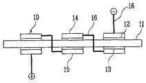
例えば、図1に示すように、電解質膜11、アノード電極12、カソード電極13、アノード集電体14、カソード集電体15、及び電気伝導のための手段または配線16を含む従来のパッシブタイプの燃料電池システムにおいて、一番目(左側)の電池セルのアノード電極と二番目(真ん中)の電池セルのカソード電極とを接続し、二番目の電池セルのアノード電極と三番目(右側)の電池セルのカソード電極とを接続するために、電解質膜11を貫通するか外側に迂回する配線が設置されなければならない。配線が電解質膜11を貫通する場合、電解質膜11の穴によってアノードとカソードとの間の気密が弱くなり、アノードに供給される燃料がカソード側に漏洩しかねないという問題がある。そして、燃料電池の外側に迂回する配線の場合、配線が長くかつ複雑であるという問題がある。
For example, as shown in FIG. 1, a conventional passive type including an
本発明が解決しようとする技術的課題は、酸化剤として、大気中の空気を直接利用するセミパッシブ方式のサンドイッチ構造のダイレクトメタノール型燃料電池アセンブリにおいて、コネクタに設置される配線を用いて電解質膜を貫通する配線を使用することなく、それぞれの電池セルに結合される複数の端子を用いて多様な出力電圧を得ることができ、実装時、通気性を確保し、外部の衝撃を遮断することができる平板型燃料電池アセンブリを提供することにある。 The technical problem to be solved by the present invention is to provide an electrolyte membrane using wiring installed in a connector in a direct methanol fuel cell assembly having a semi-passive type sandwich structure that directly uses air in the atmosphere as an oxidant. A variety of output voltages can be obtained using a plurality of terminals coupled to each battery cell without using wiring that penetrates the battery, ensuring air permeability and blocking external shocks when mounted. It is an object of the present invention to provide a flat plate fuel cell assembly.
前記技術的課題を達成するために、本発明の第1側面によると、電解質膜と、その両面に位置するアノード電極及びカソード電極からそれぞれなる複数の膜−電極接合体を備える燃料電池本体、燃料電池本体内で複数のアノード電極にそれぞれ対応して位置し、燃料電池本体の外部に突出した末端部をそれぞれ備える複数のアノード集電体、燃料電池本体内で複数のカソード電極にそれぞれ対応して位置し、燃料電池本体の外部に突出した末端部をそれぞれ備える複数のカソード集電体、そして複数のアノード集電体及び複数のカソード集電体の複数の末端部を電気的に接続するための配線を備えるコネクタを含む平板型燃料電池アセンブリが提供される。 In order to achieve the above technical problem, according to a first aspect of the present invention, a fuel cell main body comprising an electrolyte membrane and a plurality of membrane-electrode assemblies each comprising an anode electrode and a cathode electrode located on both surfaces thereof, a fuel A plurality of anode current collectors each corresponding to a plurality of anode electrodes in the battery body, each having a terminal portion protruding outside the fuel cell body, and a plurality of cathode electrodes in the fuel cell body respectively A plurality of cathode current collectors each having a terminal portion protruding to the outside of the fuel cell body, and a plurality of anode current collectors and a plurality of cathode current collectors for electrically connecting the terminal portions A flat plate fuel cell assembly including a connector with wiring is provided.
好ましくは、コネクタは、燃料電池本体の少なくとも一面にスライド結合する。 Preferably, the connector is slidably coupled to at least one surface of the fuel cell body.
さらに、コネクタは、複数の膜−電極接合体にそれぞれ結合し、燃料電池本体から複数の電圧を引き出すための複数の端子結合部を備える。 Further, the connector includes a plurality of terminal coupling portions that are coupled to the plurality of membrane-electrode assemblies, respectively, and draw a plurality of voltages from the fuel cell main body.
また、前記平板型燃料電池アセンブリは、端子結合部に結合される脚状の複数のリード端子をさらに備える。 The flat plate fuel cell assembly further includes a plurality of leg-shaped lead terminals coupled to the terminal coupling portion.
また、燃料電池本体は、燃料の流入と流出のための流入口及び流出口と、燃料の流動のためのマニホールド、及び燃料の分配供給のための複数のホールを備えるミドルプレート、ミドルプレートの両面上にそれぞれ位置する複数の膜−電極接合体、ミドルプレートと膜−電極接合体の一面との間にそれぞれ位置し、ホールを通して供給される燃料の流動をガイドするチャネルをそれぞれ備える複数のアノード集電体、膜−電極接合体の他面上にそれぞれ位置し、カソード電極を露出させる開口部をそれぞれ備える複数のカソード集電体、ミドルプレートを介してカソード集電体上に位置する一対のエンドプレート、及び一対のエンドプレートを所定圧力で締結する締結手段を備える。 The fuel cell main body includes an inlet and outlet for inflow and outflow of fuel, a manifold for fuel flow, and a middle plate having a plurality of holes for fuel supply and supply, both sides of the middle plate A plurality of anode-collectors each having a plurality of membrane-electrode assemblies respectively positioned between the middle plate and one surface of the membrane-electrode assembly, each having a channel for guiding the flow of fuel supplied through the holes. A plurality of cathode current collectors each having an opening for exposing the cathode electrode, and a pair of ends positioned on the cathode current collector via the middle plate Fastening means for fastening the plate and the pair of end plates at a predetermined pressure is provided.
本発明の第2側面によると、燃料供給のための流路を備えるミドルプレート、ミドルプレートの両面上にそれぞれ配置され、電解質膜と、その両面に接合されるアノード電極及びカソード電極からなる複数の膜−電極接合体、ミドルプレートの両面と複数の膜−電極接合体の一面との間にそれぞれ配置され、流路に連結され、燃料の流動をガイドするチャネルをそれぞれ備える複数のアノード集電体、複数の膜−電極接合体の他面上にそれぞれ配置される複数のカソード集電体、及びミドルプレートの互いに対向する両側面でアノード集電体及びカソード集電体から曲脚形状(bending leg shape)にそれぞれ突出延長される少なくとも1つの第1リード端子及び少なくとも1つの第2リード端子を含む平板型燃料電池アセンブリが提供される。 According to the second aspect of the present invention, a middle plate having a flow path for fuel supply, a plurality of electrolyte plates, and a plurality of anode electrodes and cathode electrodes, which are respectively disposed on both surfaces of the middle plate and joined to both surfaces of the electrolyte membrane, are provided. Membrane-electrode assembly, a plurality of anode current collectors each disposed between both surfaces of the middle plate and one surface of the plurality of membrane-electrode assemblies, connected to a flow path, and each having a channel for guiding the flow of fuel A plurality of cathode current collectors respectively disposed on the other surface of the plurality of membrane-electrode assemblies, and a bending leg from the anode current collector and the cathode current collector on opposite side surfaces of the middle plate. a flat plate type fuel cell assembly comprising at least one first lead terminal and at least one second lead terminal each projecting and extending on the shape). Yellowtail is provided.
好ましくは、平板型燃料電池アセンブリは、少なくとも1つの第1リード端子及び少なくとも1つの第2リード端子を支持し、平板型燃料電池アセンブリに固定結合するコネクタをさらに含む。 Preferably, the flat plate fuel cell assembly further includes a connector supporting at least one first lead terminal and at least one second lead terminal and fixedly coupling to the flat plate fuel cell assembly.
以下、本発明の属する技術分野における通常の知識を有する者が本発明を容易に実施できる好ましい実施例を、添付された図面を参照して詳細に説明する。 Hereinafter, preferred embodiments in which a person having ordinary knowledge in the technical field of the present invention can easily practice the present invention will be described in detail with reference to the accompanying drawings.
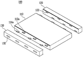
図2は、本発明の第1実施例による平板型燃料電池アセンブリを概略的に示す分解斜視図である。図3a及び図3bは、図2の平板型燃料電池アセンブリの結合構造を示す構成図である。 FIG. 2 is an exploded perspective view schematically showing a flat plate fuel cell assembly according to a first embodiment of the present invention. 3a and 3b are block diagrams showing a coupling structure of the flat plate fuel cell assembly of FIG.
図2を参照すると、本実施例の平板型燃料電池アセンブリ100は、燃料電池本体110、第1コネクタ120及び第2コネクタ130を含む。
Referring to FIG. 2, the flat plate
燃料電池本体110は、燃料と酸化剤を電気化学的に反応させて電気と熱を発生させる。燃料電池本体110は、燃料電池の必須的な構成要素である膜−電極接合体(Membrane−Electrode Assembly;MEA)を備える。膜−電極接合体は、電解質膜と、該電解質膜の両面に位置するアノード電極とカソード電極とからなる。
The fuel cell
前述の燃料電池本体110は、ポンプなどの圧縮装置を通して燃料を供給されるが、酸化剤としては、大気中の空気を用いる方式で設計される。このような構造の一例は、図7ないし図9を参照して詳細に説明する。
The fuel cell
また、燃料電池本体110は、図2から見ると、その両方の側面上で突出する第1末端部112a及び第2末端部114aを備える。第1末端部112aは、カソード集電体から延長され、第2末端部114aは、アノード集電体から延長される。
Further, when viewed from FIG. 2, the fuel cell
第1コネクタ120は、燃料電池本体110の第1側面上で突出延長される第1及び第2末端部112a、114aが挿入される結合溝122を備える。また、第1コネクタ120は、外部との電気的な接続のための端子結合部を備える。これと同様に、第2コネクタ130は、燃料電池本体110の第1側面と対向する第2側面上で突出延長される第1及び第2末端部が挿入される結合溝を備える。また、第2コネクタ130は、外部との電気的な接続のための端子結合部132を備える。
The
また、第1及び第2コネクタ120、130は、図3a及び図3bに示すように、燃料電池本体110との安定的かつ固定的な結合のために燃料電池本体110の側面にスライド結合するための構造140を備えることができる。このようなスライド結合構造140を用いると、燃料電池本体110と第1及び第2コネクタ120、130がより堅固に固定結合されることができる。
Further, the first and
図4は、図2の平板型燃料電池アセンブリの電気的な回路構成を概略的に示す図である。 FIG. 4 is a diagram schematically showing an electrical circuit configuration of the flat plate fuel cell assembly of FIG.
図4を参照すると、本実施例の平板型燃料電池アセンブリは、燃料電池本体110と、該燃料電池本体110の両側面から突出延長される末端部と電気的に接続される配線を備えたコネクタ120、130とを備える。
Referring to FIG. 4, the flat plate fuel cell assembly of the present embodiment includes a fuel cell
燃料電池本体110は、電解質膜111の一面に位置するカソード電極111aと、電解質膜111の他面上で電解質膜111を介してカソード電極111aと対向して位置するアノード電極(図示せず)からそれぞれ発生する起電力を収集するためのカソード集電体112とアノード集電体とを備える。カソード集電体112とアノード集電体は、上述したように、燃料電池本体110の外部に延長突出される末端部を備える。
The fuel cell
第1及び第2コネクタ120、130は、末端部に電気的に接続される配線131を備える。配線131は、いずれか一つの膜−電極接合体のアノード電極に接触するアノード集電体と、他の一つの膜−電極接合体のカソード電極に接触するカソード集電体とを電気的に接続する。
The first and
また、第1及び第2コネクタ120、130は、2つの膜−電極接合体を直列接続する配線131と電気的に接続され、外部電線またはリード端子との電気的な接触のための端子結合部132a、132b、132c、132d、132e、132f、132gを備える。
The first and
前述の構成によると、燃料電池本体110から複数段階の電圧及び電流の出力を得ることができる。
According to the above-described configuration, it is possible to obtain a plurality of stages of voltage and current outputs from the
図5は、本発明の第2実施例による平板型燃料電池アセンブリを示す斜視図である。 FIG. 5 is a perspective view illustrating a flat plate fuel cell assembly according to a second embodiment of the present invention.
図5を参照すると、本実施例の平板型燃料電池アセンブリは、燃料電池本体110、第1コネクタ120a、第2コネクタ130a及びリード端子150を含む。
Referring to FIG. 5, the flat plate fuel cell assembly of the present embodiment includes a
本実施例の平板型燃料電池アセンブリは、上述した第1実施例の平板型燃料電池アセンブリと比べると、複数のリード端子150が第1及び第2コネクタ120a、130aによってそれぞれ固定結合され、各コネクタ120a、130aが単に複数のリード端子150を固定支持するためのものであることに違いがある。以下の詳細な説明においては、第1実施例の構成と重複する詳細な説明はなるべく省略する。
Compared with the flat plate fuel cell assembly of the first embodiment described above, the flat plate fuel cell assembly of the present embodiment has a plurality of
リード端子150は、第1及び第2コネクタ120a、130aの端子結合部132aに結合される。つまり、複数のリード端子150は、第1及び第2コネクタ120a、130aによって一定の形態で固定設置され、燃料電池本体110から突出延長される末端部にそれぞれ電気的に接続される。
The
前述のリード端子150は、各電池セルの電圧及び電流を引き出す。したがって、本発明では、リード端子150を電気的に直列、並列、または直列と並列を組み合わせて連結することにより、多様な出力を提供することができる。また、前述のリード端子150は、平板型燃料電池アセンブリを用いるアプリケーションにおいて所定の電気的な回路配線を備える回路基板上に実装されることができる。同時に、前述のリード端子150は、平板型燃料電池アセンブリが実装面から所定の高さを持たせることにより、図5から見ると、平板型燃料電池アセンブリの上下面に露出するカソード電極に空気が円滑に供給できるように作用する。
The
一方、平板型燃料電池アセンブリは、図2または図5に示された形態で実装されるのではなく、図6に示されるように、側面に立てて実装されることができる。この場合、平板型燃料電池アセンブリは、燃料電池本体110への適切な燃料供給を考慮して、コネクタの一側面が実装面に向かうように垂直に立てて実装されることが好ましい。同時に、平板型燃料電池アセンブリが垂直に立てて実装される場合、コネクタ130に設置される端子結合部134は、実装面と対向しないように上述した実施例の側面と接する他の側面に設置されることが好ましい。
On the other hand, the flat type fuel cell assembly is not mounted in the form shown in FIG. 2 or 5 but can be mounted upright on the side as shown in FIG. In this case, in consideration of appropriate fuel supply to the fuel cell
図7は、本発明による平板型燃料電池アセンブリに採用可能な燃料電池本体と、それに対応するコネクタを示す斜視図である。 FIG. 7 is a perspective view showing a fuel cell main body that can be employed in the flat plate fuel cell assembly according to the present invention and a connector corresponding thereto.
図7を参照すると、本実施例の平板型燃料電池アセンブリ200は、燃料電池本体210、第1コネクタ220及び第2コネクタ230を含む。
Referring to FIG. 7, the flat plate
燃料電池本体210は、サンドイッチ構造と同様に、ミドルプレートを介して上下両面に対称的に位置する複数の膜−電極接合体を備える。また、燃料電池本体210は、膜−電極接合体のアノード電極とカソード電極とに結合するアノード集電体とカソード集電体とを備える。そして、燃料電池本体210は、アノード集電体とカソード集電体から外部にそれぞれ突出延長される末端部212a、214aを備える。
Similar to the sandwich structure, the fuel cell
また、燃料電池本体210は、ミドルプレートの第1側面に位置し、燃料を供給する燃料供給装置に結合される燃料流入口211bと、ミドルプレートの第1側面と対向する第2側面に位置し、燃料の排出のための燃料排出口(図示せず)とを備える。
The fuel cell
第1コネクタ220は、燃料電池本体210の第3側面上で突出延長される第1及び第2末端部が挿入される結合溝222を備える。また、第1コネクタ220は、外部との電気的な連結のための端子結合部234を備える。これと同様に、第2コネクタ230は、燃料電池本体210の第3側面と対向する第4側面上で突出延長される第1及び第2末端部212a、214aが挿入される結合溝を備える。また、第2コネクタ230は、外部との電気的な連結のための第1端子結合部232及び第2端子結合部234を備える。第1及び第2端子結合部232、234は、平板型燃料電池アセンブリ200の実装構造によって選択的に用いられることができる。
The
前述の燃料電池本体210を具体的に説明する。図8は、図7の燃料電池本体に対する分解斜視図である。
The fuel cell
図8を参照すると、燃料電池本体210は、ミドルプレート211、カソード集電体212、膜−電極接合体213、アノード集電体214、ガスケット215、エンドプレート216及び締結手段217a、217bを含む。本実施例では、ミドルプレート211の上下側にそれぞれ6個の単位電池が実質的に同一平面上に揃うように設置される。
Referring to FIG. 8, the
具体的に説明すると、ミドルプレート211は、ガスケット215、アノード集電体214、膜−電極接合体213、カソード集電体212をそれぞれ含む6個の単位電池が上下側に独立して位置するように上下面に6個の凹状に区分された領域を備え、燃料電池本体210の最外側で一対のエンドプレートに締結圧を提供するための締結手段217aが通過する穴211aを備える。
Specifically, in the
また、ミドルプレート211は、燃料の流入と流出のための流入口211b及び流出口(図示せず)を備える。そして、ミドルプレート211は、流入口211b及び流出口からミドルプレート211の内部に延長され、流入された燃料が通過するマニホールド(図示せず)、及びマニホールドから燃料の分配供給のための複数のホール211cを備える。
The
ガスケット215は、図8から見ると、ミドルプレート211の上下側でミドルプレート211とアノード集電体214との間に位置し、膜−電極接合体213のアノード電極に供給される燃料が漏洩しないように作用し、燃料電池本体210の締結時、締結圧が加えられる方向と対向する方向に弾性を提供して燃料電池本体210の密封効果を高めるように作用する。前述のガスケット215は、シリコーンなどの適切な材料を用いて図8に示された構成やそれ以外の他の適切な構造及び形態で具現されることができる。
The
アノード集電体214は、ミドルプレート211の上下側でミドルプレート211と膜−電極接合体213との間に位置する。アノード集電体214は、燃料電池本体210の外部に延長される末端部214aを備える。末端部214aは、上述した実施例の場合と同様に、コネクタとのスライド結合に適合するように、略L字状に曲がった構造を備える。
The anode
また、アノード集電体214は、アノード電極で発生する起電力を収集する。そして、アノード集電体214は、膜−電極接合体213のアノード電極に燃料を効率的に供給するためのチャネル214bを備える。チャネル214bは、蛇行状以外に、直線などの多様な形状に具現されることができる。前述のアノード集電体214は、高導電性材料で具現されることが好ましい。
The anode
膜−電極接合体213は、ミドルプレート211の上下側でアノード集電体214とカソード集電体212との間に位置する。膜−電極接合体214は、電解質膜と、該電解質膜の両面に位置するアノード電極及びカソード電極を備える。電解質膜、アノード電極及びカソード電極を既存の多様な材料及び構造で具現することができる。
The membrane-
カソード集電体212は、ミドルプレート211の上下側で膜−電極接合体213のアノード電極上に位置する。カソード集電体212は、燃料電池本体210の外部に延長される末端部212aを備える。末端部212aは、上述したように、コネクタとのスライド結合に適合するように略L字状に曲がった構造を備える。
The cathode
また、カソード集電体212は、カソード電極で発生する起電力を収集する。そして、カソード集電体212は、膜−電極接合体213のカソード電極に大気中の空気を供給するための開口部212bを備える。開口部212bは、円形ホール状以外に、四角形などの多様な構造及び大きさで具現されることができる。前述のカソード集電体212は、疎水性コーティング層を選択的に備える高導電性材料で具現されることが好ましい。高導電性材料としては、金、銀、アルミニウム、銅などの金属またはこれらの少なくとも1つを主成分とする合金、または複合材料が用いられてもよい。
The cathode
一対のエンドプレート216は、ミドルプレート211の上下側でカソード集電体212上に位置し、締結手段が通過する穴216aをそれぞれ備え、ボルト217aとナット217bとからなる締結手段によって締結される。エンドプレート216は、締結手段による締結圧が燃料電池本体210に均一に伝達される構造を備えることが好ましい。また、エンドプレート216は、空気の流れを円滑にするようにカソード集電体212の開口部212bを最大限露出させることができる構造を備えることが好ましい。そして、前述の締結手段は、ボルトとナットとからなる締結手段以外に、ベルト、空気圧、モールディングなどの既存の多様な締結手段で具現されることができる。
The pair of
図9は、図7の燃料電池本体の作動過程を説明するための図である。図9の燃料電池本体は、説明の便宜上、ミドルプレートの上下側にそれぞれ2個の単位電池を有する構造で概略的に示されている。 FIG. 9 is a view for explaining an operation process of the fuel cell main body of FIG. For convenience of explanation, the fuel cell main body of FIG. 9 is schematically shown as a structure having two unit cells on the upper and lower sides of the middle plate.
図9を参照すると、燃料電池本体210aのミドルプレート211の燃料流入口に燃料が流入すると、流入した燃料は、ミドルプレート211のマニホールドに連結されたホールを通してそれぞれのアノード集電体214に備えられたチャネルを通過する。チャネルを通過する燃料がアノード集電体214に接触するアノード電極の拡散層213a2を通して触媒層213a1に到逹すると、燃料は、触媒による酸化反応によって水素イオンと電子を発生させる。このとき、酸化剤として、空気中の酸素がカソード集電体212の開口部212bを通してカソード電極の拡散層213b2を経て触媒層213b1に供給されると、供給された酸素は、アノード電極から電解質膜213mを通過してカソード電極に至った水素イオンと外部導線219を通してアノード電極からカソード電極に移動した電子と反応して水と熱を発生させる。このとき、電子の移動は、電気を発生させる。
Referring to FIG. 9, when fuel flows into the fuel inlet of the
そして、未反応の燃料と酸化反応によって生成された二酸化炭素は、アノード流出物として、ミドルプレート21のさらに他のマニホールドに連結されたホールと燃料排出口を順次通過して排出される。また、カソード電極で発生した水は、カソード流出物として、カソード集電体212の開口部212bを通して排出される。外部導線219は、各単位電池を電気的に接続する。
The unreacted fuel and the carbon dioxide generated by the oxidation reaction are discharged as anode effluent through the holes connected to the other manifolds of the middle plate 21 and the fuel outlet sequentially. Further, water generated at the cathode electrode is discharged through the
一方、前述の電解質膜213m、触媒層213a1、213b1及び拡散層213a2、213b2に対する構成及び作用は、当業者にとって自明であるため、それらに対する詳細な説明は省略する。
On the other hand, since the configuration and operation of the
本発明によると、平板型燃料電池アセンブリの配線を容易にし、製作工程を単純化することができる。同時に、平板型燃料電池アセンブリをアプリケーションに通気性よく設置しやすく、外部の衝撃が燃料電池に伝達されることを防止することができ、多様な出力電圧を選択的に用いることができるという利点がある。 According to the present invention, the wiring of the flat fuel cell assembly can be facilitated, and the manufacturing process can be simplified. At the same time, it is easy to install a flat type fuel cell assembly in an air-permeable manner in an application, can prevent external shocks from being transmitted to the fuel cell, and can selectively use various output voltages. is there.
以上、本発明の好ましい実施例を挙げて詳細に説明したが、本発明は、上記の実施例に限定されるのではなく、本発明の技術的思想の範囲内で当分野における通常の知識を有する者によって多様に変形されることができる。 The present invention has been described in detail with reference to the preferred embodiments. However, the present invention is not limited to the above-described embodiments, but has ordinary knowledge in the art within the scope of the technical idea of the present invention. It can be modified in various ways by the person who has it.
100 平板型燃料電池アセンブリ
110 燃料電池本体
112a、114a 末端部
120 第1コネクタ
122 結合溝
130 第2コネクタ
132 端子結合部
DESCRIPTION OF
Claims (12)
前記燃料電池本体内で前記複数のアノード電極にそれぞれ対応して位置し、前記燃料電池本体の外部に突出した末端部をそれぞれ備える複数のアノード集電体、
前記燃料電池本体内で前記複数のカソード電極にそれぞれ対応して位置し、前記燃料電池本体の外部に突出した末端部をそれぞれ備える複数のカソード集電体、及び
前記複数のアノード集電体及び前記複数のカソード集電体の複数の末端部を電気的に接続するための配線を備えるコネクタを含む平板型燃料電池アセンブリ。 A fuel cell main body comprising an electrolyte membrane, and a plurality of membrane-electrode assemblies each comprising an anode electrode and a cathode electrode located on both surfaces of the electrolyte membrane;
A plurality of anode current collectors respectively corresponding to the plurality of anode electrodes in the fuel cell main body and provided with end portions protruding to the outside of the fuel cell main body;
A plurality of cathode current collectors respectively corresponding to the plurality of cathode electrodes in the fuel cell body, each having a terminal portion protruding to the outside of the fuel cell body; and the plurality of anode current collectors and A flat plate fuel cell assembly including a connector having wiring for electrically connecting a plurality of end portions of a plurality of cathode current collectors.
燃料の流入と流出のための流入口及び流出口と、前記燃料の流動のためのマニホールド、及び前記燃料の分配供給のための複数のホールを備えるミドルプレート、
前記ミドルプレートの両面上にそれぞれ位置する前記複数の膜−電極接合体、
前記ミドルプレートと前記膜−電極接合体の一面との間にそれぞれ位置し、前記ホールを通して供給される前記燃料の流動をガイドするチャネルをそれぞれ備える前記複数のアノード集電体、
前記膜−電極接合体の他面上にそれぞれ位置し、前記カソード電極を露出させる開口部をそれぞれ備える前記複数のカソード集電体、
前記ミドルプレートを介して前記複数のカソード集電体上に位置する一対のエンドプレート、及び
前記一対のエンドプレートを所定圧力で締結する締結手段を備える請求項1に記載の平板型燃料電池アセンブリ。 The fuel cell body is
A middle plate having an inlet and an outlet for inflow and outflow of fuel, a manifold for flow of the fuel, and a plurality of holes for distributing and supplying the fuel;
The plurality of membrane-electrode assemblies respectively located on both sides of the middle plate;
A plurality of anode current collectors each disposed between the middle plate and one surface of the membrane-electrode assembly, each having a channel for guiding the flow of the fuel supplied through the hole;
A plurality of cathode current collectors, each of which is located on the other surface of the membrane-electrode assembly, each having an opening for exposing the cathode electrode;
2. The flat plate fuel cell assembly according to claim 1, further comprising: a pair of end plates positioned on the plurality of cathode current collectors via the middle plate; and a fastening unit that fastens the pair of end plates at a predetermined pressure.
前記ミドルプレートの両面上にそれぞれ配置され、電解質膜と、前記電解質膜の両面に接合されるアノード電極及びカソード電極からなる複数の膜−電極接合体、
前記ミドルプレートの両面と前記複数の膜−電極接合体の一面との間にそれぞれ配置され、前記流路に連結され、前記燃料の流動をガイドするチャネルをそれぞれ備える複数のアノード集電体、
前記複数の膜−電極接合体の他面上にそれぞれ配置される複数のカソード集電体、及び
前記ミドルプレートの互いに対向する両側面で前記アノード集電体及び前記カソード集電体から曲脚形状にそれぞれ突出延長される少なくとも1つの第1リード端子及び少なくとも1つの第2リード端子を含む平板型燃料電池アセンブリ。 A middle plate with a flow path for fuel supply,
A plurality of membrane-electrode assemblies comprising an electrolyte membrane and an anode electrode and a cathode electrode respectively disposed on both sides of the middle plate and joined to both sides of the electrolyte membrane;
A plurality of anode current collectors each disposed between both surfaces of the middle plate and one surface of the plurality of membrane-electrode assemblies, each having a channel connected to the flow path and guiding the flow of the fuel;
A plurality of cathode current collectors respectively disposed on the other surface of the plurality of membrane-electrode assemblies; and a curved leg shape from the anode current collector and the cathode current collector on opposite side surfaces of the middle plate A flat plate fuel cell assembly including at least one first lead terminal and at least one second lead terminal each projecting and extending.
The flat plate fuel cell assembly according to claim 11, wherein the fastening means includes a screw coupling means that penetrates the pair of end plates and the middle plate.
Applications Claiming Priority (1)
| Application Number | Priority Date | Filing Date | Title |
|---|---|---|---|
| KR1020060001118A KR20070073340A (en) | 2006-01-04 | 2006-01-04 | Flat type fuel cell assembly having housing |
Publications (1)
| Publication Number | Publication Date |
|---|---|
| JP2007184228A true JP2007184228A (en) | 2007-07-19 |
Family
ID=37969751
Family Applications (1)
| Application Number | Title | Priority Date | Filing Date |
|---|---|---|---|
| JP2006194701A Pending JP2007184228A (en) | 2006-01-04 | 2006-07-14 | Flat fuel cell assembly provided with connector |
Country Status (5)
| Country | Link |
|---|---|
| US (1) | US20070154761A1 (en) |
| EP (1) | EP1806802A3 (en) |
| JP (1) | JP2007184228A (en) |
| KR (1) | KR20070073340A (en) |
| CN (1) | CN100524922C (en) |
Cited By (3)
| Publication number | Priority date | Publication date | Assignee | Title |
|---|---|---|---|---|
| JP2008235277A (en) * | 2007-03-22 | 2008-10-02 | Samsung Sdi Co Ltd | Fuel cell system |
| WO2010116893A1 (en) * | 2009-04-10 | 2010-10-14 | 株式会社 東芝 | Fuel cell |
| JP2013502686A (en) * | 2009-08-17 | 2013-01-24 | ミオクサイド マイニング (ピーティーワイ)リミテッド | Fuel cell |
Families Citing this family (6)
| Publication number | Priority date | Publication date | Assignee | Title |
|---|---|---|---|---|
| JP5011759B2 (en) * | 2006-03-07 | 2012-08-29 | トヨタ自動車株式会社 | Fuel cell with cell voltage monitor |
| KR100908973B1 (en) * | 2007-09-13 | 2009-07-22 | 삼성에스디아이 주식회사 | Fuel cell system |
| US8735012B2 (en) * | 2008-11-20 | 2014-05-27 | Mti Microfuel Cells Inc. | Direct oxidation fuel cell system with uniform vapor delivery of fuel |
| TWI427308B (en) * | 2011-10-18 | 2014-02-21 | Iner Aec Executive Yuan | Testing device for solid oxide fuel cell |
| FR3025968B1 (en) * | 2014-09-15 | 2016-10-14 | Dcns | SUBMARINE ENGINE WITH LINES OF ENERGY STORAGE MEANS |
| KR102168803B1 (en) * | 2018-04-17 | 2020-10-22 | 주식회사 엘지화학 | Apparatus for evaluating the performance of a fuel cell stack |
Family Cites Families (14)
| Publication number | Priority date | Publication date | Assignee | Title |
|---|---|---|---|---|
| US4827606A (en) | 1988-05-11 | 1989-05-09 | The United States Of America As Represented By The United States Department Of Energy | Method and apparatus for assembling solid oxide fuel cells |
| US6096449A (en) * | 1997-11-20 | 2000-08-01 | Avista Labs | Fuel cell and method for controlling same |
| US6127058A (en) * | 1998-10-30 | 2000-10-03 | Motorola, Inc. | Planar fuel cell |
| JP4124972B2 (en) * | 2001-02-23 | 2008-07-23 | Necトーキン株式会社 | Stacked lithium-ion battery |
| US6503653B2 (en) * | 2001-02-23 | 2003-01-07 | General Motors Corporation | Stamped bipolar plate for PEM fuel cell stack |
| JP4672892B2 (en) | 2001-03-30 | 2011-04-20 | 本田技研工業株式会社 | Fuel cell stack |
| US20020187382A1 (en) * | 2001-06-06 | 2002-12-12 | Hiroaki Nishiumi | Mounting structure of fuel cell assembly on vehicle body |
| JP4042101B2 (en) | 2001-07-06 | 2008-02-06 | ソニー株式会社 | FUEL CELL AND POWER SUPPLY METHOD USING FUEL CELL |
| AU2002313280A1 (en) | 2001-12-07 | 2003-06-17 | Canon Kabushiki Kaisha | Fuel battery and electric device |
| US6998188B2 (en) | 2002-02-19 | 2006-02-14 | Petillo Phillip J | Fuel cell components |
| KR100450820B1 (en) * | 2002-04-23 | 2004-10-01 | 삼성에스디아이 주식회사 | Air breathing direct methanol fuel cell pack |
| US7316368B2 (en) * | 2003-01-17 | 2008-01-08 | Suncast Corporation | Direct current powered hose rewinding apparatus |
| JP4398652B2 (en) | 2003-02-24 | 2010-01-13 | 富士通コンポーネント株式会社 | Fuel cell device |
| JP3773910B2 (en) * | 2003-03-04 | 2006-05-10 | 株式会社東芝 | Fuel cell unit for electronic equipment |
-
2006
- 2006-01-04 KR KR1020060001118A patent/KR20070073340A/en not_active Application Discontinuation
- 2006-07-14 JP JP2006194701A patent/JP2007184228A/en active Pending
-
2007
- 2007-01-03 US US11/649,390 patent/US20070154761A1/en not_active Abandoned
- 2007-01-03 EP EP07100071A patent/EP1806802A3/en not_active Withdrawn
- 2007-01-04 CN CNB2007100012348A patent/CN100524922C/en not_active Expired - Fee Related
Cited By (3)
| Publication number | Priority date | Publication date | Assignee | Title |
|---|---|---|---|---|
| JP2008235277A (en) * | 2007-03-22 | 2008-10-02 | Samsung Sdi Co Ltd | Fuel cell system |
| WO2010116893A1 (en) * | 2009-04-10 | 2010-10-14 | 株式会社 東芝 | Fuel cell |
| JP2013502686A (en) * | 2009-08-17 | 2013-01-24 | ミオクサイド マイニング (ピーティーワイ)リミテッド | Fuel cell |
Also Published As
| Publication number | Publication date |
|---|---|
| EP1806802A2 (en) | 2007-07-11 |
| CN1996651A (en) | 2007-07-11 |
| CN100524922C (en) | 2009-08-05 |
| EP1806802A3 (en) | 2008-09-10 |
| KR20070073340A (en) | 2007-07-10 |
| US20070154761A1 (en) | 2007-07-05 |
Similar Documents
| Publication | Publication Date | Title |
|---|---|---|
| KR100879875B1 (en) | End plate for fuel cell stack and air breathing type fuel cell stack using the same | |
| JP4842072B2 (en) | Fuel cell and fuel cell system having the same | |
| JP2007184228A (en) | Flat fuel cell assembly provided with connector | |
| JP5127770B2 (en) | Stack and fuel cell power generation system having the same | |
| JP2006253135A (en) | Stack for fuel cell and fuel cell system using stack for fuel cell | |
| US20080070082A1 (en) | Fuel cell | |
| KR101387451B1 (en) | Electrochemical device | |
| US20090068519A1 (en) | Fuel cell and method of manufacturing the same | |
| KR101155911B1 (en) | Stack for fuel cell system | |
| JP5109570B2 (en) | Fuel cell stack | |
| US8053132B2 (en) | Cathode end plate and breathable fuel cell stack using the same | |
| JP5255849B2 (en) | Fuel cell and separator / seal structure | |
| CN111989810A (en) | Fuel cell | |
| KR20100033618A (en) | Current collector and stack of fuel cell | |
| JP2008293953A (en) | Stack for fuel cell | |
| WO2005050766A1 (en) | Fuel cell | |
| KR100684781B1 (en) | Stack and fuel cell apparatus with the same | |
| JP2005216535A (en) | Fuel cell | |
| US20060051653A1 (en) | Fuel cell system and stack | |
| US20240014429A1 (en) | Fuel cell unit | |
| KR100709224B1 (en) | Direct oxydation fuel cell | |
| KR100709223B1 (en) | Direct oxydation fuel cell | |
| JP4643178B2 (en) | Fuel cell | |
| KR100658281B1 (en) | Electron collector pair and single-plate multi-cell stack | |
| KR100696682B1 (en) | Stack for fuel cell and fuel cell apparatus with the same |
Legal Events
| Date | Code | Title | Description |
|---|---|---|---|
| A131 | Notification of reasons for refusal |
Free format text: JAPANESE INTERMEDIATE CODE: A131 Effective date: 20100209 |
|
| A521 | Request for written amendment filed |
Free format text: JAPANESE INTERMEDIATE CODE: A523 Effective date: 20100510 |
|
| A02 | Decision of refusal |
Free format text: JAPANESE INTERMEDIATE CODE: A02 Effective date: 20110614 |