JP2007183111A - Light intensity detection device, optical device provided with same, and microscope - Google Patents
Light intensity detection device, optical device provided with same, and microscope Download PDFInfo
- Publication number
- JP2007183111A JP2007183111A JP2006000180A JP2006000180A JP2007183111A JP 2007183111 A JP2007183111 A JP 2007183111A JP 2006000180 A JP2006000180 A JP 2006000180A JP 2006000180 A JP2006000180 A JP 2006000180A JP 2007183111 A JP2007183111 A JP 2007183111A
- Authority
- JP
- Japan
- Prior art keywords
- light
- laser
- light intensity
- intensity detection
- microscope
- Prior art date
- Legal status (The legal status is an assumption and is not a legal conclusion. Google has not performed a legal analysis and makes no representation as to the accuracy of the status listed.)
- Pending
Links
Images

Classifications
-
- G—PHYSICS
- G02—OPTICS
- G02B—OPTICAL ELEMENTS, SYSTEMS OR APPARATUS
- G02B21/00—Microscopes
- G02B21/0096—Microscopes with photometer devices
Abstract
Description
本発明は、光学装置における光強度検出装置に関する。 The present invention relates to a light intensity detection device in an optical device.
従来、レーザー光源からの光を音響光学素子(以後、本明細書中ではAOTFと記す)で特定の波長を選択すると同時にレーザー光の強度を調節し、光路中に配設された分離ミラーによって一部のレーザー光を分離してレーザー光の光強度を光検強度検出器で光強度を検出することが知られている(例えば、特許文献1参照)。
しかしながら、特許文献1に開示されている構成の光強度検出では、AOTFを通過したレーザー光の一部はAOTFで散乱されてレーザー光の周りに同心円状に広がる(以後、フレアーと記す)。このフレアーはAOTFに加える電圧に係わらずほぼ一定である。この結果、AOTFに加える電圧をゼロにしてもフレアーのために光強度検出器の出力値はゼロとならず正確なレーザー光の光強度を検出することが困難であるという問題がある。 However, in the light intensity detection of the configuration disclosed in Patent Document 1, a part of the laser light that has passed through the AOTF is scattered by the AOTF and spreads concentrically around the laser light (hereinafter referred to as flare). This flare is substantially constant regardless of the voltage applied to the AOTF. As a result, there is a problem that even if the voltage applied to the AOTF is zero, the output value of the light intensity detector does not become zero due to flare and it is difficult to detect the accurate light intensity of the laser beam.
本発明は、上記課題に鑑みて行われたものであり、AOTFのフレアーの影響を受けない光強度検出装置とこれを有する光源装置、顕微鏡を提供することを目的とする。 The present invention has been made in view of the above problems, and an object of the present invention is to provide a light intensity detection device that is not affected by the flare of AOTF, a light source device having the light intensity detection device, and a microscope.
上記課題を解決するために、本発明は、光源から射出された光の光路に配設された音響光学素子と、前記音響光学素子から射出された光の光路に配設され、前記光の一部を分岐する分岐光学素子と、前記分岐された光の強度を検出する光検出器と、前記音響光学素子と前記光検出器の間の光路に配設された偏光子とを有することを特徴とする光強度検出装置を提供する。 In order to solve the above problems, the present invention provides an acoustooptic device disposed in an optical path of light emitted from a light source, and an optical path of light emitted from the acoustooptic device. A branching optical element for branching a part, a photodetector for detecting the intensity of the branched light, and a polarizer disposed in an optical path between the acoustooptic element and the photodetector. A light intensity detecting device is provided.
また、本発明は、前記光強度検出装置を有する顕微鏡を提供する。 The present invention also provides a microscope having the light intensity detection device.
また、本発明は、前記光強度検出装置を有する光源装置を提供する。 Moreover, this invention provides the light source device which has the said light intensity detection apparatus.
また、本発明は、前記光源装置を有する顕微鏡を提供する。 The present invention also provides a microscope having the light source device.
本発明によれば、AOTFのフレアーの影響を受けない光強度検出装置とこれを有する光源装置、顕微鏡を提供することができる。 ADVANTAGE OF THE INVENTION According to this invention, the light intensity detection apparatus which is not influenced by the flare of AOTF, and a light source device and microscope which have this can be provided.
以下、本発明の実施の形態に関し図面を参照しつつ説明する。 Embodiments of the present invention will be described below with reference to the drawings.
(第1実施の形態)
図1は、本発明に係る光強度検出器装置を有する光源装置とこの光源装置からのレーザー光を照明光として用いるレーザー顕微鏡を示す。
(First embodiment)
FIG. 1 shows a light source device having a light intensity detector device according to the present invention and a laser microscope using laser light from the light source device as illumination light.
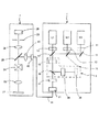
図1において、1は複数のレーザー光源L1、L2,L3を有する光源装置である。2は光源装置1から射出されたレーザー光を用いて標本を観察するレーザー顕微鏡である。
In FIG. 1, reference numeral 1 denotes a light source device having a plurality of laser light sources L1, L2, and L3.
光源装置1は、複数のレーザー光源L1.L2、L3を有している。レーザー光源L1、L2、L3は射出するレーザー光の波長がそれぞれ異なっている。なお、レーザー光源の数は3個に限定されるものではない。レーザー光源L1から射出されたレーザー光は、ダイクロイックミラー17を透過してAOTF32に入射する。また、レーザー光源L2から射出されたレーザー光はダイクロイックミラー16でダイクロイックミラー17方向に反射されダイクロイックミラー17で反射され、レーザー光源L1と同一の光軸とされてAOTF32に入射する。また、レーザー光源L3から射出されたレーザー光は、ダイクロイックミラー15でダイクロイックミラー16方向に反射され、ダイクロイックミラー16を透過してダイクロイックミラー17で反射され、レーザー光源L1と同一の光軸とされてAOTF32に入射する。この様にして、レーザー光源L1、L2,L3それぞれから射出されたレーザー光は、同一の光軸上を進行する。レーザー光源L1、L2、L3とダイクロイックミラー17、16、15のそれぞれの間の光路にはシャッター13、12、11が配設され、不図示の制御装置によってAOTF32に入射するレーザ光源が選択される。
The light source device 1 includes a plurality of laser light sources L1. L2 and L3. The laser light sources L1, L2, and L3 have different wavelengths of emitted laser light. Note that the number of laser light sources is not limited to three. Laser light emitted from the laser light source L1 passes through the
AOTF32に入射したレーザー光は、不図示の制御装置からの信号に基づきレーザー光の光強度がAOTF32で調節されて分岐光学素子18に入射する。分岐光学素子18は入射したレーザー光の一部を反射し、その他を透過する特性を有している。分岐光学素子18には、ガラス板が用いられるが反射強度が調整されたハーフミラーであっても良い。分岐光学素子18で反射されたレーザー光は、AOTF32で発生したフレアーを除去するために設けられた偏光子19に入射して透過し光検出器20に入射して、レーザー光の光強度が検出される。偏光子19の偏光方向は、AOTF32を射出したレーザー光と同一の方向に設定されている。上記のAOTF32、分岐光学素子18、偏光子19、および光検出器20で光強度検出装置3が構成されいる。
The laser light incident on the AOTF 32 is incident on the branch
分岐光学素子18を透過したレーザー光は、シャッター14を介してファイバーカップリング21に入射する。シャッター14は、不図示の制御装置で開閉が制御される。この様にして、光源装置1が構成されている。
The laser light transmitted through the branch
光源装置1のファイバーカップリング21に接続された光ファイバー31は、レーザー顕微鏡2の照明光学系のファイバーカップリング41に接続され、レーザー顕微鏡20の光源として使用される。ファイバーカップリング41から射出したレーザー光は、コリメータレンズ22で略平行光にされダイクロイックミラー25で対物レンズ23方向に反射され、XYスキャナー26に入射し、対物レンズ23で標本27上に集光される。レーザー光はXYスキャナー26で二次元走査されるので、結果的に標本27上をXY二次元方向に走査することができる。
The
標本27で反射されたレーザー光は、対物レンズ23で集光されXYスキャナー26でデスキャンされてダイクロイックミラー25を透過して集光レンズ24でピンホール28に結像される。ピンホール28を透過した光は光検出器29で検出され、不図示の画像処理装置で処理された後不図示のモニターに表示されて観察される。この様にしてレーザー顕微鏡2が構成されている。なお、レーザー顕微鏡2はダイクロイックミラー25をダイクロイックミラーと蛍光フィルターが組み合わされたフィルターセットと交換することによって標本27からの蛍光を観察することも可能である。
The laser beam reflected by the
光強度検出装置3のAOTF32は、不図示の制御装置から加えられる信号の周波数によって波長を、電圧によって通過するレーザー光の光量を変えることができる。また、AOTF32に入射するレーザー光は直線偏光であることが必要である。
The
AOTF32を通過後のレーザー光は入射レーザー光に対して偏光方向が90度回転した直線偏光となっている。AOTF32を透過したレーザー光は、0次光と1次光に分かれるが、光量を調節したり波長を選択したりできるのは1次光であり、この1次光が分岐光学素子18に向け入射されて照明光として使用される。0次光は図示しない遮光板で遮光され分岐光学素子18には入射しないように構成されている。
The laser light after passing through the AOTF 32 is linearly polarized light whose polarization direction is rotated by 90 degrees with respect to the incident laser light. The laser light that has passed through the AOTF 32 is divided into zero-order light and primary light, but it is the primary light that can adjust the amount of light and select the wavelength, and this primary light enters the branching
AOTF32は、結晶の回折を利用しており散乱光による1次光の光軸を中心とする同心円状のフレアーが発生する。このフレアーは、無偏光の光でありAOTF32に加える電圧によらず一定量発生し、レーザー光を最小にする電圧を加えてもフレアーは消えずに残っている。この結果、フレアーは分岐光学素子18で反射されて光検出器20に入射して検出されてしまい正確なレーザー光の光強度を測定することが難しくなる。なお、ファイバーカップリング21における入射レーザー光の径は小さく、あるいは光ファイバー31の径が小さく、光軸を中心として同心円状に発生するフレアーの径は大きいため、フレアーがファイバーカップリング21の入射端面、あるいは光ファイバー31の入射端面に入射することは無い。
The AOTF 32 utilizes crystal diffraction and generates concentric flares centered on the optical axis of primary light due to scattered light. This flare is non-polarized light and is generated in a constant amount regardless of the voltage applied to the
本発明に係る光強度検出装置3は、分岐光学素子18と光検出器20との間に偏光子19を配設している。偏光子19の偏光方向は分岐光学素子18で反射されたレーザー光の偏光方向と同一な方向に設定されているため、レーザー光を透過し無偏光のフレアーを遮光することができる。この結果、光検出器20にフレアーが入射することを防止することができAOTF32に加える電圧を最小にしてレーザー光をゼロにすれば光検出器20で検出する光強度もゼロとなりレーザー光の正確な光強度を検出することが可能となる。なお、偏光子19は、AOTF32と分岐光学素子18との間に配設することも可能であるが、このときは偏光子19を光路中に挿入したことによるレーザー光の光量低下があることを考慮する必要がある。しかし、レーザー光源に十分な光量があるときは、ファイバーカップリング21方向に向かうレーザー光のフレアーもカットできるので好ましい。
In the light
また、分岐光学素子18とファイバーカップリング21との間にシャッター14を設けてあり、レーザー光の光量調節時にはシャッター14を閉じてAOTF32に加える電圧を調整することができる。調整後シャッター14を開放にてレーザー光をファイバーカップリング21に入射して光ファイバー31を介してレーザー顕微鏡2の照明光として使用することができる。また、光検出器20の出力を不図示の制御装置に導き、光検出器20の出力値が一定となるようにAOTF32に加える電圧を制御することで、レーザー光源の出力変動があってもファイバーカップリング21方向に出射するレーザー光の強度を一定に維持することが可能になり、例えばタイムラプス測定などの長時間測定の光源として使用することが可能になる。
Further, a
また、分岐光学素子18で分岐されたレーザー光の光強度(光検出器20の検出強度)と標本27に照射される光強度(別の光検出器で測定された光強度)との相関関係を予め測定しておくことで、光検出器20の出力値から換算して標本27に照射されるレーザー光の光強度を表示することが可能になる。
Further, the correlation between the light intensity of the laser beam branched by the branching optical element 18 (detection intensity of the light detector 20) and the light intensity irradiated to the sample 27 (light intensity measured by another light detector). Is measured in advance, it is possible to display the light intensity of the laser light irradiated on the
この様に、本発明に係る光強度検出装置3によれば、AOTF32で発生するフレアーをカットしてレーザー光のみを光検出器20に入射することができるので、正確なレーザー光の光強度の測定が可能になる。また、光強度検出装置3を内蔵することで、光検出器20の信号を用いて正確な光強度のレーザー光を長時間維持することができタイムラプス等に好適な光源装置1を構成することが可能になる。また、光源装置1をレーザー顕微鏡2の光源として用いることで、正確な光強度のレーザー光を標本に照射することが可能になる。
As described above, according to the light
(第2実施の形態)
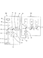
図2は、本発明に係る光強度検出装置を内蔵するレーザー顕微鏡と光源装置の概略構成図である。第1実施の形態と同様の構成には同じ符号を付し説明を省略する。
(Second Embodiment)
FIG. 2 is a schematic configuration diagram of a laser microscope and a light source device incorporating a light intensity detection device according to the present invention. The same components as those in the first embodiment are denoted by the same reference numerals and description thereof is omitted.
図2において、光源装置101は第1実施の形態において光強度検出装置3を除いたものでありその他の構成は第1実施の形態と同様であり説明を省略する。
In FIG. 2, the
光源装置101からの選択されたレーザー光は、光ファイバー31とファイバーカップリング41を介してレーザー顕微鏡102の照明光学系に入射される。ファイバーカップリング41を射出したレーザー光は、コリメータレンズ22で略平行光にされて
AOTF32に入射される。AOTF32でレーザー光の光強度が調節されて分岐光学素子18方向に射出され、分岐光学素子18で一部が反射されて、偏光子19を通過して光検出器20に入射する。分岐光学素子18を透過したレーザー光は、ダイクロイックミラー25に入射して対物レンズ23方向に反射され、XYスキャナー26を介して対物レンズ23に入射し標本27に集光される。その他の構成は、第1実施の形態と同様であり説明を省略する。光強度検出装置3の作用および効果は第1実施の形態と同様である。
The selected laser light from the
本第2実施の形態では、光強度検出装置3がレーザー顕微鏡102に内蔵されているので、光源装置101を色々交換して使用することが可能であり、レーザー光源の波長等を種々選択することができる。したがって、一般的な光源装置をレーザー顕微鏡に取り付けるだけで正確なレーザー光の光強度が測定可能な顕微鏡が得られる。
In the second embodiment, since the light
(第3実施の形態)
図3は、本発明に係る光強度検出装置を内蔵するレーザー顕微鏡の概略構成図である。第1実施の形態と同様の構成には同じ符号を付し説明を省略する。本第3実施の形態では、光源装置もレーザー顕微鏡に内蔵されており、顕微鏡と光源装置が一体となった構成となっている。
(Third embodiment)
FIG. 3 is a schematic configuration diagram of a laser microscope incorporating the light intensity detection device according to the present invention. The same components as those in the first embodiment are denoted by the same reference numerals and description thereof is omitted. In the third embodiment, the light source device is also built in the laser microscope, and the microscope and the light source device are integrated.
図3において、レーザー光源L1、L2、L3からシャッター14までの構成は第1実施の形態の光源装置1と同様である。光強度検出装置3は、ダイクロイックミラー17とシャッター14との間の光路に配設され、第1実施の形態と同様の作用をしている。
In FIG. 3, the configuration from the laser light sources L1, L2, and L3 to the
シャッター14を出射したレーザー光は、レーザー顕微鏡100の照明光学系のコリメータレンズ42でピンホール43に集光される。ピンホール43に集光されたレーザー光は、集光レンズ22で略平行光にされてダイクロイックミラー25に入射する。その他の構成は第1実施の形態と同様であり説明を省略する。この様にしてレーザー顕微鏡100が構成されている。光強度検出装置3の作用および効果は第1実施の形態と同様である。
The laser light emitted from the
本第3実施の形態では、光検出装置3および光源装置をレーザー顕微鏡100内蔵するレーザー顕微鏡システムを構成することができる。レーザー顕微鏡100の制御装置を介して標本に照射するレーザー光の強度等を制御することが可能である。さらにタイムラプス等の長時間測定において光強度の安定したレーザー光を供給することができる。また、コンフォーカル顕微鏡にも適用可能である。また、本発明では、光検出器の受光面の大きさが入射光のスポット径に対して十分に大きい場合、特に有効である。
In the third embodiment, a laser microscope system in which the
なお、上述の実施の形態は例に過ぎず、上述の構成や形状に限定されるものではなく、本発明の範囲内において適宜修正、変更が可能である。 The above-described embodiment is merely an example, and is not limited to the above-described configuration and shape, and can be appropriately modified and changed within the scope of the present invention.
1、101 光源装置
2,100、102 レーザー顕微鏡
11 、12、13、14 シャッター
15,16,17,25 ダイクロイックミラー
18 分岐光学素子
19 偏光子
20 光検出器
21、41 ファイバーカップリング
22 コリメータレンズ
24、42 集光レンズ
23 対物レンズ
26 XYスキャナー
27 標本
28、43 ピンホール
29 光検出器
31 光ファイバー
32 音響光学素子(AOTF)
L1、L2,L3 レーザー光源
DESCRIPTION OF SYMBOLS 1,101 Light source device 2,100,102
L1, L2, L3 Laser light source
Claims (6)
前記音響光学素子から射出された光の光路に配設され、前記光の一部を分岐する分岐光学素子と、
前記分岐された光の強度を検出する光検出器と、
前記音響光学素子と前記光検出器の間の光路に配設された偏光子とを有することを特徴とする光強度検出装置。 An acoustooptic device disposed in the optical path of the light emitted from the light source;
A branching optical element disposed in the optical path of the light emitted from the acoustooptic element and branching a part of the light;
A photodetector for detecting the intensity of the branched light;
A light intensity detection device comprising: a polarizer disposed in an optical path between the acoustooptic device and the photodetector.
Priority Applications (1)
| Application Number | Priority Date | Filing Date | Title |
|---|---|---|---|
| JP2006000180A JP2007183111A (en) | 2006-01-04 | 2006-01-04 | Light intensity detection device, optical device provided with same, and microscope |
Applications Claiming Priority (1)
| Application Number | Priority Date | Filing Date | Title |
|---|---|---|---|
| JP2006000180A JP2007183111A (en) | 2006-01-04 | 2006-01-04 | Light intensity detection device, optical device provided with same, and microscope |
Publications (2)
| Publication Number | Publication Date |
|---|---|
| JP2007183111A true JP2007183111A (en) | 2007-07-19 |
| JP2007183111A5 JP2007183111A5 (en) | 2009-03-12 |
Family
ID=38339346
Family Applications (1)
| Application Number | Title | Priority Date | Filing Date |
|---|---|---|---|
| JP2006000180A Pending JP2007183111A (en) | 2006-01-04 | 2006-01-04 | Light intensity detection device, optical device provided with same, and microscope |
Country Status (1)
| Country | Link |
|---|---|
| JP (1) | JP2007183111A (en) |
Cited By (2)
| Publication number | Priority date | Publication date | Assignee | Title |
|---|---|---|---|---|
| KR100978600B1 (en) | 2007-10-23 | 2010-08-27 | 연세대학교 산학협력단 | Scanning optical measurement apparatus having super resolution |
| EP2458420A1 (en) | 2010-11-26 | 2012-05-30 | Olympus Corporation | Light intensity measuring unit and microscope including the same |
Citations (10)
| Publication number | Priority date | Publication date | Assignee | Title |
|---|---|---|---|---|
| JPH0752453A (en) * | 1993-08-13 | 1995-02-28 | Fuji Photo Film Co Ltd | Image recording device |
| JPH07159381A (en) * | 1993-12-13 | 1995-06-23 | Hitachi Ltd | Method and apparatus for detecting photo-acoustic signal |
| JP2000199855A (en) * | 1998-11-02 | 2000-07-18 | Olympus Optical Co Ltd | Scanning type optical microscopic device |
| US6167173A (en) * | 1997-01-27 | 2000-12-26 | Carl Zeiss Jena Gmbh | Laser scanning microscope |
| JP2001100103A (en) * | 1999-09-28 | 2001-04-13 | Olympus Optical Co Ltd | Scanning type laser microscope |
| JP2003522323A (en) * | 1998-12-28 | 2003-07-22 | アメルシャム・バイオサイエンシーズ・アクチボラグ | Fluorescence emission measurement device |
| JP2004045225A (en) * | 2002-07-11 | 2004-02-12 | National Aerospace Laboratory Of Japan | Spectrum polarizing measuring device using acoustooptical filter |
| JP2004537747A (en) * | 2001-07-30 | 2004-12-16 | ライカ ミクロジュステムス ハイデルベルク ゲーエムベーハー | Optical device and scanning microscope |
| JP2005031678A (en) * | 2003-07-11 | 2005-02-03 | Carl Zeiss Jena Gmbh | Arrangement for catching lighting beam in laser scanning microscope and its method |
| JP2005148497A (en) * | 2003-11-17 | 2005-06-09 | Olympus Corp | Scanning type laser microscope system |
-
2006
- 2006-01-04 JP JP2006000180A patent/JP2007183111A/en active Pending
Patent Citations (10)
| Publication number | Priority date | Publication date | Assignee | Title |
|---|---|---|---|---|
| JPH0752453A (en) * | 1993-08-13 | 1995-02-28 | Fuji Photo Film Co Ltd | Image recording device |
| JPH07159381A (en) * | 1993-12-13 | 1995-06-23 | Hitachi Ltd | Method and apparatus for detecting photo-acoustic signal |
| US6167173A (en) * | 1997-01-27 | 2000-12-26 | Carl Zeiss Jena Gmbh | Laser scanning microscope |
| JP2000199855A (en) * | 1998-11-02 | 2000-07-18 | Olympus Optical Co Ltd | Scanning type optical microscopic device |
| JP2003522323A (en) * | 1998-12-28 | 2003-07-22 | アメルシャム・バイオサイエンシーズ・アクチボラグ | Fluorescence emission measurement device |
| JP2001100103A (en) * | 1999-09-28 | 2001-04-13 | Olympus Optical Co Ltd | Scanning type laser microscope |
| JP2004537747A (en) * | 2001-07-30 | 2004-12-16 | ライカ ミクロジュステムス ハイデルベルク ゲーエムベーハー | Optical device and scanning microscope |
| JP2004045225A (en) * | 2002-07-11 | 2004-02-12 | National Aerospace Laboratory Of Japan | Spectrum polarizing measuring device using acoustooptical filter |
| JP2005031678A (en) * | 2003-07-11 | 2005-02-03 | Carl Zeiss Jena Gmbh | Arrangement for catching lighting beam in laser scanning microscope and its method |
| JP2005148497A (en) * | 2003-11-17 | 2005-06-09 | Olympus Corp | Scanning type laser microscope system |
Cited By (3)
| Publication number | Priority date | Publication date | Assignee | Title |
|---|---|---|---|---|
| KR100978600B1 (en) | 2007-10-23 | 2010-08-27 | 연세대학교 산학협력단 | Scanning optical measurement apparatus having super resolution |
| EP2458420A1 (en) | 2010-11-26 | 2012-05-30 | Olympus Corporation | Light intensity measuring unit and microscope including the same |
| US8619252B2 (en) | 2010-11-26 | 2013-12-31 | Olympus Corporation | Microscope including a light intensity measuring unit for measuring an intensity of light emitted from the microscope |
Similar Documents
| Publication | Publication Date | Title |
|---|---|---|
| JP4315794B2 (en) | Confocal microscope | |
| JP6346615B2 (en) | Optical microscope and microscope observation method | |
| JP4670031B2 (en) | Apparatus for optical detection of a light beam that has undergone excitation and / or backscattering in a sample | |
| KR100743591B1 (en) | Confocal Self-Interference Microscopy Which Excluding Side Lobes | |
| JP4817356B2 (en) | Optical microscope | |
| US7872799B2 (en) | Device for controlling light radiation | |
| US9297980B2 (en) | Optical device for transmission-type scanning by moving scanning beam without moving observation sample | |
| US20040150880A1 (en) | Confocal microscope | |
| US7684048B2 (en) | Scanning microscopy | |
| US7915575B2 (en) | Laser scanning microscope having an IR partial transmission filter for realizing oblique illumination | |
| US9804029B2 (en) | Microspectroscopy device | |
| WO2020034299A1 (en) | Parallel multi-area imaging device | |
| US20130100461A1 (en) | Methods and apparatuses for position and force detection | |
| JP2001324678A (en) | Optical path deviation detecting device and confocal microscope | |
| US9843719B2 (en) | Confocal microscope | |
| JP2009540346A (en) | Interference confocal microscope | |
| JP5472780B2 (en) | Hole shape measuring apparatus and optical system | |
| JP2007183111A (en) | Light intensity detection device, optical device provided with same, and microscope | |
| CN116481983A (en) | Coaxial interference scattering microscopic imaging device and method based on polarized illumination | |
| JPH01188816A (en) | Spectral type scanning microscope | |
| JP2011058953A (en) | Detector, optical apparatus with the same | |
| JP2008175884A (en) | Laser microscope | |
| JP2005331419A (en) | Microscopic spectral measuring instrument | |
| US20100199393A1 (en) | Probe microscope | |
| JPH10232352A (en) | Laser scan microscope |
Legal Events
| Date | Code | Title | Description |
|---|---|---|---|
| A621 | Written request for application examination |
Free format text: JAPANESE INTERMEDIATE CODE: A621 Effective date: 20081127 |
|
| A521 | Written amendment |
Free format text: JAPANESE INTERMEDIATE CODE: A523 Effective date: 20090126 |
|
| A977 | Report on retrieval |
Free format text: JAPANESE INTERMEDIATE CODE: A971007 Effective date: 20101118 |
|
| A131 | Notification of reasons for refusal |
Free format text: JAPANESE INTERMEDIATE CODE: A131 Effective date: 20101214 |
|
| A02 | Decision of refusal |
Free format text: JAPANESE INTERMEDIATE CODE: A02 Effective date: 20110419 |